Illustrative Figure
Abstract
An example game controller is removably attachable to a main unit. The game controller includes a controller-side slide member. The controller-side slide member protrudes from a first surface of the game controller and is configured to slidably engage with the main unit-side slide member in a slide direction. The controller-side slide member has a first end and a second end in the slide direction, and the game controller is configured to be attached to the main unit by inserting the controller-side slide member into the main unit-side slide member. The controller-side slide member includes a protruding portion and at least one terminal. The protruding portion protrudes from the first end side of the controller-side slide member in the slide direction and has a facing surface that faces the first surface of the game controller. The at least one terminal is between the facing surface and the first surface.
Description
DETAILED DESCRIPTION OF NON-LIMITING EXAMPLE EMBODIMENTS An information processing system, an information processing device, a controller device and an accessory according to an example of the present embodiment will now be described. In the present embodiment, the information processing system includes an information processing device1and a cradle5(seeFIG. 28). The information processing device1of the present embodiment includes a main unit2and controllers3and4, which can be attached to and detached from each other, and the controllers3and4can be used separately from the main unit2(seeFIG. 2). The information processing device1can be used both in a mode of use in which images are displayed on the main unit2and in another mode of use in which images are displayed on a separate display device such as a TV. The information processing device1is used as a portable device (e.g., a portable game device) in the former mode, and the information processing device1is used as a console-type device (e.g., a console-type game device) in the latter mode. [1. External Configuration of System] [1-1. Configuration of Information Processing Device] FIG. 1is a diagram showing an example information processing device1according to the present embodiment. As shown inFIG. 1, the information processing device1includes a main unit2, a left controller3and a right controller4. The main unit2, including a display12, executes various processes of the information processing device1. The controllers3and4each include an operation section allowing a user to provide an input(s). The example left-right orientation shown inFIG. 1is non-limiting. As shown inFIG. 1andFIG. 2, the controllers3and4can be attached to and detached from the main unit2.FIG. 2is a diagram showing an example where the controllers3and4are detached from the main unit2. The left controller3can be attached to the left side of the main unit2(the x-axis positive direction side shown inFIG. 1) and can also be detached therefrom. The right controller4can be attached to the right side ...
DETAILED DESCRIPTION OF NON-LIMITING EXAMPLE EMBODIMENTS
An information processing system, an information processing device, a controller device and an accessory according to an example of the present embodiment will now be described. In the present embodiment, the information processing system includes an information processing device1and a cradle5(seeFIG. 28). The information processing device1of the present embodiment includes a main unit2and controllers3and4, which can be attached to and detached from each other, and the controllers3and4can be used separately from the main unit2(seeFIG. 2). The information processing device1can be used both in a mode of use in which images are displayed on the main unit2and in another mode of use in which images are displayed on a separate display device such as a TV. The information processing device1is used as a portable device (e.g., a portable game device) in the former mode, and the information processing device1is used as a console-type device (e.g., a console-type game device) in the latter mode.
[1. External Configuration of System]
[1-1. Configuration of Information Processing Device]
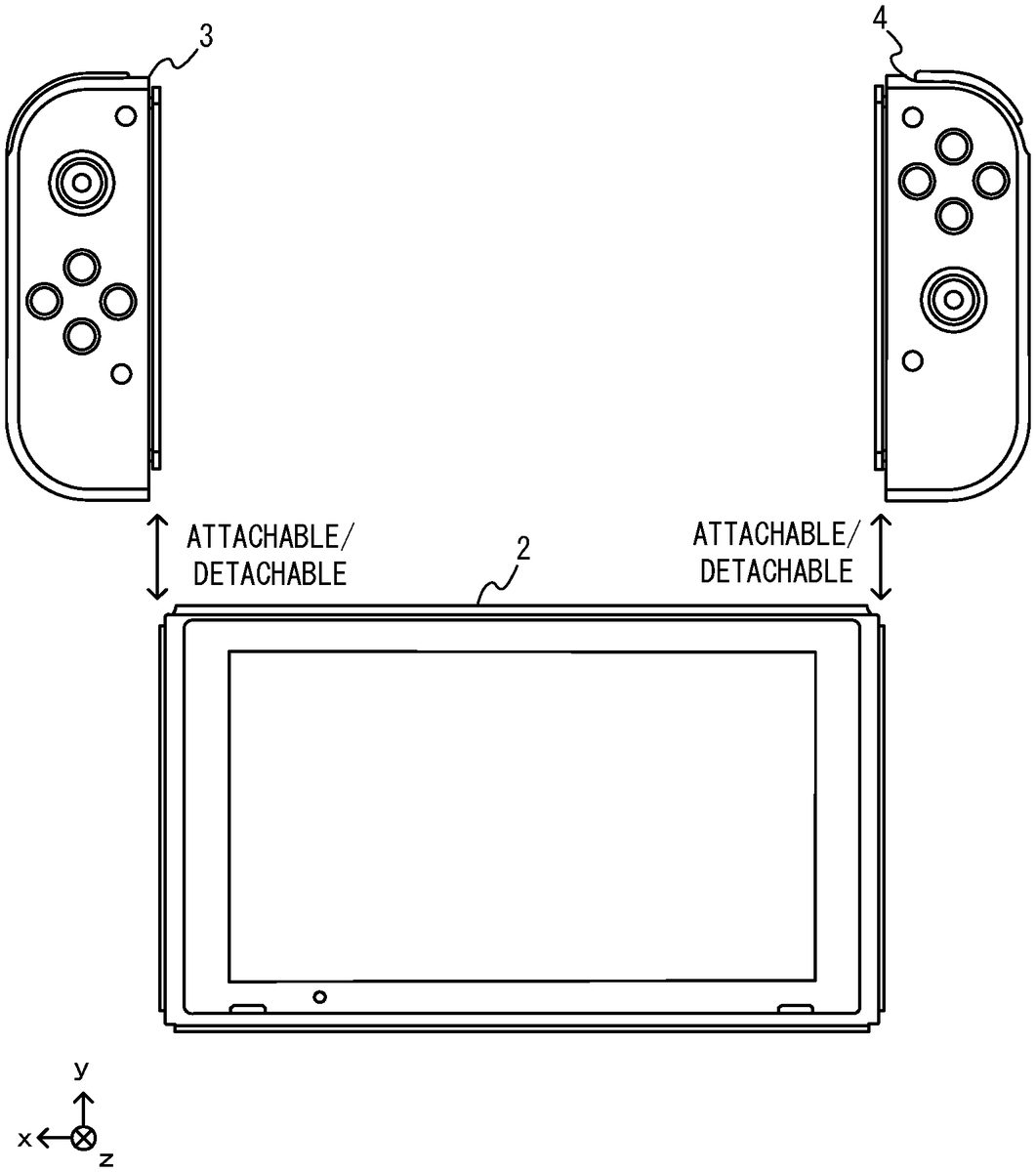
FIG. 1is a diagram showing an example information processing device1according to the present embodiment. As shown inFIG. 1, the information processing device1includes a main unit2, a left controller3and a right controller4. The main unit2, including a display12, executes various processes of the information processing device1. The controllers3and4each include an operation section allowing a user to provide an input(s). The example left-right orientation shown inFIG. 1is non-limiting.
As shown inFIG. 1andFIG. 2, the controllers3and4can be attached to and detached from the main unit2.FIG. 2is a diagram showing an example where the controllers3and4are detached from the main unit2. The left controller3can be attached to the left side of the main unit2(the x-axis positive direction side shown inFIG. 1) and can also be detached therefrom. The right controller4can be attached to the right side of the main unit2(the x-axis negative direction side shown inFIG. 1) and can also be detached therefrom. Note that the left controller and the right controller may be referred to generally as “controllers”. A specific example configuration of the main unit2and the controllers3and4will now be described.
[1-1-1. Configuration of Main Unit]
FIG. 3is a six-sided view showing an example main unit. As shown inFIG. 3, the main unit2includes a generally plate-shaped or planar housing11. In the present embodiment, the primary surface (in other words, the front-side surface, i.e., the surface on which the display12is provided) of the housing11has a generally rectangular shape. In the present embodiment, the housing11has a horizontally-elongated shape. That is, in the present embodiment, the longitudinal direction of the primary surface of the housing11(i.e., the x-axis direction shown inFIG. 1) is denoted as the horizontal direction (also referred to as the left-right direction), the width direction of the primary surface (i.e., the y-axis direction shown inFIG. 1) is denoted as the vertical direction (also referred to as the up-down direction), and the direction perpendicular to the primary surface (i.e., the z-axis direction shown inFIG. 1) is denoted as the depth direction (also referred to as the front-rear direction). Note that the main unit2may be used in a landscape orientation or may be used in a portrait orientation.
Note that there is no particular limitation on the shape and the size of the housing11. For example, in other embodiments, the housing11may include a projection or a grip portion for making it easier for a user to hold the device.
(Elements Provided on Primary Surface of Housing11)
As shown inFIG. 3, the main unit2includes the display12provided on the primary surface of the housing11. The display12displays an image (which may be a still image or a video or other moving image) obtained or produced by the main unit2. While the display12is assumed to be a liquid crystal display device (LCD) in the present embodiment, it may be any type of a display device.
The main unit2includes a touch panel13on the screen of the display12such that display12functions as a touch screen. The touch panel may sense position, pressure or other characteristics of touch. In the present embodiment, the touch panel13is of a type (e.g., the capacitive type) that enables a multi-touch input. Note however that there is no particular limitation on the type of the touch panel13, and the touch panel13may be of a type (e.g., the resistive type) that enables a single-touch input, for example.
The main unit2includes a speaker (i.e., a speaker88shown inFIG. 30) inside the housing11. As shown inFIG. 3, speaker holes11aand11bare formed in the primary surface of the housing11. Output sounds from the speaker88are output through these speaker holes11aand11b. In the present embodiment, the main unit2includes two speakers, and speaker holes are located respectively for the left speaker and the right speaker. The speaker hole11afor the left speaker is formed in a left portion of the display12. The speaker hole11bfor the right speaker is formed in a right portion of the display12.
The main unit2also includes an ambient light sensor (i.e., an ambient light sensor94shown inFIG. 30) inside the housing11. As shown inFIG. 3, a window portion14is provided in the primary surface of the housing11so as to allow light from outside the housing11to be received by the ambient light sensor94. The window portion14is provided for example as a transparent member that allows light to pass therethrough, or a filter member that allows light of a predetermined wavelength(s) that can be sensed by the ambient light sensor94to pass therethrough.
Note that there is no particular limitation on the position, the shape and the number of the speaker holes11aand11band the window portion14. For example, in other embodiments, the speaker holes11aand11bmay be provided on the side surface or the back surface of the housing11. While the window portion14is provided on the lower left side of the display12in the present embodiment, it may be provided in any other position on the primary surface of the housing11or may be provided on the side surface of the housing11.
(Elements Provided on Left Side Surface of Housing11)
As shown inFIG. 3, the main unit2includes a left rail member15on the left side surface of the housing11. The left rail member15is a member that allows the left controller3to be detachably attached to the main unit2so that a user can easily attach the left controller to the main unit2to mechanically and electrically join the two pieces together so that the pieces function as a single integrated unit, and yet the user can also easily detach the left controller from the main unit to allow the main unit and the left controller to operate while mechanically separated from one another. The left rail member15is provided so as to extend in the up-down direction on the left side surface of the housing11. The left rail member15has such a shape that can engage with a slider of the left controller3(i.e., a slider40shown inFIG. 5). The left rail member15and the slider40together form a slide mechanism, the details of which will be described later. This slide mechanism allows the left controller3to be slidably and detachably attached to the main unit2.
In the present embodiment, the left rail member15has a shape with a groove. In other words, the cross section (specifically, the cross section perpendicular to the up-down direction) of the left rail member15is C-shaped. More specifically, the cross section of the left rail member15is such that the end portions of the cross section extend in the outside-to-center direction. Therefore, the slider40in engagement with the left rail member15is securely locked so as not to come off in the direction perpendicular to the sliding direction (in other words, the direction in which the left rail member15extends) (seeFIG. 7to be discussed below).
As shown inFIG. 3, the left rail member15is provided with an engagement hole16. The engagement hole16is located so as to face a projection41provided on the slider40when the left controller3is attached to the main unit2. There is no particular limitation on the specific position of the engagement hole16. In the present embodiment, the engagement hole16is provided on the bottom surface of the left rail member15(in other words, the bottom surface of the groove of the left rail member15). The engagement hole16is shaped so that the projection (i.e., the projection41shown inFIG. 5) can engage with the engagement hole16. When the left controller3is attached to the main unit2, the projection41is inserted into and engages with the engagement hole16, thereby locking the left controller3to the main unit2, the details of which will be described later. Note that in other embodiments, the left rail member15may be provided with a projection and the slider40may be provided with an engagement hole.
The main unit2includes a left-side terminal17. The left-side terminal17allows the main unit2to communicate with the left controller3in wired communication—in other words, when the left controller and the main unit are attached to one another, they can electrically communicate via the left side terminal. The left-side terminal17is located so as to be in contact with the terminal of the left controller3(a terminal42shown inFIG. 5) when the left controller3is attached to the main unit2. There is no particular limitation on the specific position of the left-side terminal17. In the present embodiment, as shown inFIG. 3, the left-side terminal17is provided on the bottom surface of the left rail member15. In the present embodiment, the left-side terminal17is provided near the lower end on the bottom surface of the left rail member15. The left-side terminal17is provided below the engagement hole16(in other words, on the far side with respect to the direction in which the slider40is inserted into the left rail member15).
A stopper18is provided on the left side surface of the housing11. As shown inFIG. 3, the stopper18is provided near the end (in the present embodiment, near the lower end) of the left rail member15. The stopper18is provided inside the groove of the left rail member15. The stopper18is provided in order to limit the slide of the slider40in engagement with the left rail member15, the details of which will be described later.
(Elements Provided on Right Side Surface of Housing11)
As shown inFIG. 3, similar elements to those provided on the left side surface of the housing11are provided on the right side surface of the housing11. That is, the main unit2includes a right rail member19on the right side surface of the housing11. The right rail member19is provided so as to extend in the up-down direction on the right side surface of the housing11. The right rail member19has such a shape that it can engage with a slider of the right controller4(i.e., a slider62shown inFIG. 6). The right rail member19and the slider62together form a slide mechanism, the details of which will be described later. This slide mechanism allows the right controller4to be slidably and detachably attached to the main unit2.
In the present embodiment, the right rail member19has a similar shape to that of the left rail member15. That is, the right rail member19has a shape with a groove whose cross-sectional shape is similar to that of the left rail member15. Note however that the right rail member19does not need to have exactly the same shape as that of the left rail member15. For example, in other embodiments, the groove of the left rail member15and the groove of the right rail member19may differ from each other in terms of the size and/or the shape so that the slider62of the right controller4cannot engage with the left rail member15(and/or so that the slider40of the left controller3cannot engage with the right rail member19).
As shown inFIG. 3, the right rail member19is provided with an engagement hole20. The engagement hole20is located so as to face a projection63provided on the slider62when the right controller4is attached to the main unit2. There is no particular limitation on the specific position of the engagement hole20. In the present embodiment, the engagement hole20is provided on the bottom surface of the right rail member19(in other words, the bottom surface of the groove of the right rail member19). The engagement hole20is shaped so that the projection (i.e., the projection63shown inFIG. 6) can engage with the engagement hole20. When the right controller4is attached to the main unit2, the projection63is inserted into and engages with the engagement hole20, thereby locking the right controller4to the main unit2, the details of which will be described later. Note that in other embodiments, the right rail member19may be provided with a projection and the slider62with an engagement hole.
The main unit2includes a right-side terminal21. The right-side terminal21allows the main unit2to communicate with the right controller4in wired communication. The right-side terminal21is located so as to be in contact with the terminal of the right controller4(a terminal64shown inFIG. 6) when the right controller4is attached to the main unit2. There is no particular limitation on the specific position of the right-side terminal21. In the present embodiment, as shown inFIG. 3, the right-side terminal21is provided on the bottom surface of the right rail member19. In the present embodiment, the right-side terminal21is provided near the lower end on the bottom surface of the right rail member19. The right-side terminal21is provided below the engagement hole20(in other words, on the far side with respect to the direction in which the slider62is inserted into the right rail member19).
A stopper22is provided on the right side surface of the housing11. As shown inFIG. 3, the stopper22is provided near the end (in the present embodiment, near the lower end) of the right rail member19. The stopper22is provided inside the groove of the right rail member19. The stopper22is provided in order to limit the slide of the slider62in engagement with the right rail member19, the details of which will be described later.
As described above, in the present embodiment, the housing11of the main unit2is provided with the left rail member15and the right rail member19. Thus, the housing11is configured on the assumption that controllers are attached thereto. Note that there is no particular limitation on the position, the shape and the size of the rail members15and19. For example, in other embodiments, the rail members15and19may be provided on the left and right end portions, respectively, on the primary surface and/or the reverse surface of the housing11. There is no particular limitation on the mechanism for allowing the controllers3and4to be detachably attached to the main unit2, and a slider mechanism different from that of the present embodiment may be used, or a mechanism different from a slider mechanism may be used.
(Elements Provided on Upper Side Surface of Housing11)
As shown inFIG. 3, the main unit2includes a first slot23. The first slot23is provided on the upper side surface of the housing11. The first slot23is shaped so as to accommodate a storage medium of a first type. Note that in the present embodiment, a cover that can be opened/closed is provided for the opening of the first slot23, and a storage medium of the first type can be inserted into the first slot23with the cover being open. A storage medium of the first type is, for example, a dedicated storage medium (e.g., a dedicated memory card) for the information processing device1or other information processing devices of the same type. The storage medium of the first type is used, for example, for storing data used in the main unit2(e.g., application save data, etc.) and/or for storing programs to be executed on the main unit2(e.g., application programs, etc.).
The main unit2also includes a power button28. As shown inFIG. 3, the power button28is provided on the upper side surface of the housing11. The power button28is a button for turning ON/OFF the power of the main unit2. Note that in the present embodiment, the power button28can be used to switch between the ON mode and the sleep mode. The ON mode is a mode in which the screen display of the display12is turned on, for example, and the sleep mode is a mode in which the screen display of the display12is turned off, for example. In the sleep mode, in addition to (or instead of) turning off the screen display of the display12, a predetermined process of the application (e.g., a game process of a game application) may be stopped. When a long-press operation is performed on a power button28(specifically, when the power button28is held down for a predetermined period of time or longer), the main unit2executes a process of turning ON/OFF the power of the main unit2. On the other hand, when a short-press operation is performed on the power button28(specifically, when the power button28is held down for a period of time that is shorter than the predetermined period of time), the main unit2executes a process of switching between the ON mode and the sleep mode.
As described above, in the present embodiment, the power button28can be used to turn the power ON/OFF and to switch between the ON mode and the sleep mode. Note that in other embodiments, the main unit2may be provided with a button only for the function of turning the power ON/OFF or only for the function of switching between the ON mode and the sleep mode.
The main unit2includes a sound input/output terminal (specifically, an earphone jack)25. That is, the main unit2allows a microphone or an earphone to be attached to the sound input/output terminal25. As shown inFIG. 3, the sound input/output terminal25is provided on the upper side surface of the housing11.
The main unit2includes sound volume buttons26aand26b. As shown inFIG. 3, the sound volume buttons26aand26bare provided on the upper side surface of the housing11. The sound volume buttons26aand26bare buttons for giving instructions to adjust the volume of the sound output from the main unit2. That is, the sound volume button26ais a button for giving an instruction to lower the sound volume, and the sound volume button26bis a button for giving an instruction to raise the sound volume.
The housing11is provided with an air outlet hole11c. As shown inFIG. 3, the air outlet hole11cis provided on the upper side surface of the housing11. The air outlet hole11cis provided so as to radiate (in other words, discharge) the heat generated inside the housing11to the outside of the housing11for cooling purposes.
(Elements Provided on Lower Side Surface of Housing11)
The main unit2includes a lower terminal27. The lower terminal27is a terminal for allowing the main unit2to communicate with the cradle5to be described later. As shown inFIG. 3, the lower terminal27is provided on the lower side surface of the housing11. The lower terminal27is connected to a terminal of the cradle5(a main body terminal73shown inFIG. 29) when the main unit2is attached to the cradle5, the details of which will be described later. In the present embodiment, the lower terminal27is a USB connector (more specifically, a female-side connector).
The main unit2also includes a second slot24. In the present embodiment, the second slot24is provided on the lower side surface of the housing11. Note however that in other embodiments, the second slot24may be provided on the same surface as the first slot23. The second slot24is shaped so as to accommodate a storage medium of a second type, which is different from the first type. Note that in the present embodiment, a cover that can be opened/closed is provided for the opening of the second slot24, and a storage medium of the second type can be inserted into the second slot24with the cover being open. A storage medium of the second type may be, for example, a general-purpose storage medium, e.g., an SD card. As is the storage medium of the first type, the storage medium of the second type is used for storing data used in the main unit2(e.g., application save data, etc.) and/or for storing programs to be executed on the main unit2(e.g., application programs, etc.).
The housing11is provided with an air inlet hole11d. As shown inFIG. 3, the air inlet hole11dis provided on the lower side surface of the housing11. The air inlet hole11dis provided so as to take in (in other words, introduce) the air from the outside of the housing11to the inside of the housing11. In the present embodiment, the air inlet hole11dis provided on the surface opposite from the surface where the air outlet hole11cis provided, thereby allowing for efficient discharge of the heat from inside the housing11.
The main unit2also includes a stand member29used when placing the housing upright. As shown inFIG. 3, the stand member29is provided on the lower side surface of the housing11. The stand member29is rotatably connected to the housing11via a pivot29a. InFIG. 3, the stand member29is accommodated in the housing11.
FIG. 4is a diagram showing an example in which the main unit2is placed upright. Note that in order to facilitate understanding of elements of interest to be discussed in conjunction with the figure, some of the other elements of the main unit2are not shown inFIG. 4. The rod-shaped portion of the stand member29protrudes from the housing11after being rotated about the pivot29a. Thus, the stand member29is brought into a position protruding from the housing11, allowing the main unit2to be placed upright as shown inFIG. 4. Note that the mechanism for placing the main unit2upright is not limited to the stand member29shown inFIG. 3, but may be any other mechanism.
There is no particular limitation on the shape, the number and the arrangement of the various elements (specifically, the buttons, the slots, the terminals, etc.) provided on the housing11described above. For example, in other embodiments, some of the power button28and the slots23and24may be provided on another side surface or the back surface of the housing11. In other embodiments, some of the elements described above may be absent on the main unit2.
[1-1-2. Configuration of Left Controller]
FIG. 5is a six-sided view showing an example of the left controller3. As shown inFIG. 5, the left controller3includes a generally plate-shaped housing31. In the present embodiment, the primary surface (in other words, the front-side surface, i.e., the surface on the z-axis negative direction side shown inFIG. 1) of the housing31has a generally rectangular shape. In the present embodiment, the housing31has a vertically-elongated shape, i.e., a shape that is elongated in the up-down direction (i.e., the y-axis direction shown inFIG. 1). Note that when detached from the main unit2, the left controller3may be held in a portrait position (seeFIG. 38) or may be held in a landscape position (seeFIG. 35). Note that there is no particular limitation on the shape of the housing31, and the housing31does not need to be generally plate-shaped in other embodiments. The housing31does not need to have a rectangular shape, but may have a semi-circular shape, or the like, for example. The housing31does not need to have a vertically-elongated shape.
The length of the housing31in the up-down direction is generally equal to the length of the housing11of the main unit2in the up-down direction. The thickness of the housing31(i.e., the length thereof in the front-rear direction; in other words, the length thereof in the z-axis direction shown inFIG. 1) is generally equal to the thickness of the housing11of the main unit2. Therefore, when the left controller3is attached to the main unit2(seeFIG. 1), a user can hold the main unit2and the left controller3as if they were an integral unit.
As shown inFIG. 5, the left-side corner portion of the primary surface of the housing31has a more rounded shape than the right-side corner portion thereof. That is, the connecting portion between the upper side surface and the left side surface of the housing31and the connecting portion between the lower side surface and the left side surface of the housing31are more rounded (in other words, round-cornered with a greater radius) than the connecting portion between the upper side surface and the right side surface and the connecting portion between the lower side surface and the right side surface. Therefore, when the left controller3is attached to the main unit2(seeFIG. 1), the left side of the information processing device1will have a rounded shape, making it easier for a user to hold the device.
The left controller3includes an analog stick32. As shown inFIG. 5, the analog stick32is provided on the primary surface of the housing31. The analog stick32is an example of a directional input section allowing a user to input a direction. The analog stick32includes a stick member that can be tilted in any direction (i.e., 360° directions including the upper, lower, left, right and diagonal directions) parallel to the primary surface of the housing31. A user can tilt the stick member to make a direction input based on the tilt direction (and a magnitude input based on the tilt angle). Note that the directional input section may also be a cross-shaped key, a slide stick, or the like. A slide stick is an input section including a stick member that can be slid in any direction parallel to the primary surface of the housing31, and a user can slide the stick member to make an input based on the slide direction (and a magnitude input based on the slide amount). In the present embodiment, a user can also make an input by pressing down the stick member (in a direction vertical to the housing31). That is, the analog stick32is an input section that allows a user to make a direction input and a magnitude input based on the tilt direction and the tilt amount, respectively, of the stick member, and also to make a push input by pressing down the stick member.
The left controller3includes four operation buttons33to36(specifically, a right direction button33, a lower direction button34, an upper direction button35and a left direction button36). As shown inFIG. 5, these four operation buttons33to36are provided below the analog stick32on the primary surface of the housing31. Note that while four operation buttons are provided on the primary surface of the left controller3in the present embodiment, there is no particular limitation on the number of operation buttons. These operation buttons33to36are used to give instructions in accordance with various programs executed on the main unit2(e.g., the OS program and application programs). Note that in the present embodiment, the operation buttons33to36can be used to make directional inputs, and the operation buttons33to36are therefore referred to as the right direction button33, the lower direction button34, the upper direction button35and the left direction button36. Note however that the operation buttons33to36may be used to give instructions other than directional inputs.
The left controller3also includes a record button37. As shown inFIG. 5, the record button37is provided on the primary surface of the housing31, more specifically, in a lower right area of the primary surface. The record button37is a button for giving an instruction to save the image displayed on the display12of the main unit2. For example, when a game image is displayed on the display12, a user can press the record button37to save the game image that is displayed at the point in time when the button is pressed in a storage section of the main unit2, for example.
The left controller3also includes a minus (−) button47. As shown inFIG. 5, the minus button47is provided on the primary surface of the housing31, more specifically, in an upper right area of the primary surface. The minus button47is used to give instructions in accordance with various programs executed on the main unit2(e.g., the OS program and application programs). The minus button47is used, for example, as a select button (e.g., a button used to move the selection through different selection items) in game applications.
When the left controller3is attached to the main unit2, the operation sections provided on the primary surface of the left controller3(specifically, the analog stick32and the buttons33to37and47) are operated with the thumb of the left hand, for example, of a user holding the information processing device1(seeFIG. 33). When the left controller3is used detached from the main unit2, the operation sections are operated with the left and right thumbs, for example, of a user holding the left controller3(seeFIG. 34). Specifically, in such a case, the analog stick32is operated by the thumb of the left hand of the user, and the operation buttons33to36are operated with the thumb of the right hand of the user.
The left controller3includes a first L button38. The left controller3also includes a ZL button39. As are the operation buttons33to36, these operation buttons38and39are used to give instructions in accordance with various programs executed on the main unit2. As shown inFIG. 5, the first L button38is provided over a corner portion between the left side surface and the upper side surface of the housing31. The ZL button39is provided to extend over a corner portion between the left side surface and the upper side surface of the housing31(strictly speaking, between the left side surface and the upper side surface as seen from the front side of the housing31) while extending into the reverse surface of the housing31. That is, the ZL button39is provided on the rear side (the z-axis positive direction side shown inFIG. 1) of the first L button38. In the present embodiment, since the upper left corner portion of the housing31has a rounded shape, the first L button38and the ZL button39each have a rounded shape in conformity with the rounded shape of the upper left corner portion of the housing31.
When the left controller3is attached to the main unit2, the first L button38and the ZL button39will be placed over the upper left portion of the information processing device1(seeFIG. 1). Therefore, a user holding the information processing device1is allowed to operate the first L button38and the ZL button39with the index finger or the middle finger of the left hand (seeFIG. 33).
As shown inFIG. 5, a portion of the reverse surface of the housing31where the ZL button39is provided (more specifically, at least a portion of the perimeter of the ZL button39) projects past other portions of the housing31. The ZL button39is provided so as to project past the other portions of the housing31on the reverse surface. Therefore, when the main unit2with the left controller3attached thereto is placed on a flat surface in such an orientation that the reverse surface of the left controller3faces the horizontal flat surface, the projecting portions of the housing31are in contact with the flat surface. As a result, the information processing device1is placed so that the upper side of the main unit2is slightly raised from the lower side thereof. When the information processing device1is so placed, it is easy for a user to see the display12.
Note that in other embodiments, when the main unit2with the left controller3attached thereto is placed on a flat surface in such an orientation that the reverse surface of the left controller3faces the horizontal flat surface, the ZL button39may be in contact with the flat surface. Now, in the present embodiment, the ZL button39can be pressed down primarily in the up-down direction (the y-axis direction). That is, the ZL button39is supported on the housing31so as to move primarily in the up-down direction. Therefore, even if the information processing device1is placed so that the ZL button39is in contact with the flat surface as described above, the ZL button39is unlikely to be pressed down because the ZL button39primarily receives a force in the front-rear direction (the z-axis direction). That is, even when the information processing device1is placed as described above, the ZL button39is unlikely to be pressed down inadvertently.
In other embodiments, the ZL button39may be provided so as not to project from the reverse surface of the housing31. For example, the ZL button39may be provided on the side surface of the housing31. For example, an area of the reverse surface of the housing31where the ZL button39is provided may be sunken from the remaining portion (i.e., the housing is formed to be thinner in this area) so that the ZL button39does not project past the remaining portion of the reverse surface.
The left controller3includes the slider40described above. As shown inFIG. 5, the slider40is provided so as to extend in the up-down direction on the right side surface of the housing31. The slider40has such a shape that it can engage with the left rail member15(more specifically, the groove of the left rail member15) of the main unit2. Specifically, the cross section (specifically, the cross section perpendicular to the up-down direction) of the slider40is T-shaped. More specifically, the cross section of the slider40is T-shaped in conformity with the cross-sectional shape of the left rail member15(seeFIG. 7). Therefore, the slider40in engagement with the left rail member15is locked so as not to come off in the direction perpendicular to the sliding direction (in other words, the direction in which the left rail member15extends) (seeFIG. 7to be discussed below).
As shown inFIG. 5, the slider40is provided with the projection41. The projection41is arranged at such a position that allows the projection41to be inserted into the engagement hole16when the left controller3is attached to the main unit2. There is no particular limitation on the specific position of the projection41. In the present embodiment, the projection41is provided on the engaging surface of the slider40. Note that the engaging surface of the slider40refers to a surface that faces the bottom surface of the left rail member15when the left controller3is attached to the main unit2. The projection41is shaped so that the projection41can engage with the engagement hole16of the left rail member15.
In the present embodiment, the projection41is biased from the inside of the slider40toward the outside of the slider40. Thus, when a force from the outside of the slider40toward the inside of the slider40is applied on the projection41, the projection41moves toward the inside of the slider40(i.e., retracts into the slider40). There is no particular limitation on the configuration for biasing the projection41as described above. For example, in the present embodiment, the projection41is connected to an elastic member inside the slider40, and the projection41is placed inside a hole in the slider40with a portion thereof protruding past the engaging surface of the slider40. Note that in other embodiments, the projection41may be fixed to the slider40.
The left controller3includes the terminal42for allowing the left controller3to communicate with the main unit2in wired communication. The terminal42is located so as to be in contact with the left-side terminal17of the main unit2(FIG. 3) when the left controller3is attached to the main unit2. There is no particular limitation on the specific position of the terminal42. In the present embodiment, as shown inFIG. 5, the terminal42is provided on the engaging surface of the slider40. In the present embodiment, the terminal42is provided near the lower end on the engaging surface of the slider40. The terminal42is provided below the projection41(in other words, on the front side with respect to the insertion of the slider40into the left rail member15).
The left controller3also includes a second L button43and a second R button44. As are the other operation buttons33to36, these buttons43and44are used to give instructions in accordance with various programs executed on the main unit2. As shown inFIG. 5, the second L button43and the second R button44are provided on the engaging surface of the slider40. The second L button43is provided on the engaging surface of the slider40above the center of the engaging surface with respect to the up-down direction (the y-axis direction shown inFIG. 1). The second R button44is provided on the engaging surface of the slider40below the center of the engaging surface with respect to the up-down direction. The second L button43and the second R button44are arranged at such positions that they cannot be pressed down with the left controller3attached to the main unit2. That is, the second L button43and the second R button44are buttons that are used when the left controller3is detached from the main unit2. For example, the second L button43and the second R button44are operated with the index finger or the middle finger of the left hand and the right hand of a user holding the left controller3detached from the main unit2(seeFIG. 35).
The left controller3includes an indicator LED45. The indicator LED45is an indicator section for indicating predetermined information to the user. There is no particular limitation on the information to be indicated by the indicator LED45. In the present embodiment, the indicator LED45shows the user identification information of the controller when the main unit2communicates with a plurality of controllers. Specifically, as the indicator LED45, the left controller3includes a number (herein, four) of LEDs equal to the number of controllers that the main unit2can be simultaneously in communication with. Then, one of the four LEDs is lit, which is associated with the number assigned to the controller. Thus, it is possible with the indicator LED45to indicate the number to the user.
In other embodiments, the indicator LED45may indicate, to the user, the status of communication between the left controller3and the main unit2. For example, the indicator LED45may be lit while a connection with the main unit2is established. While the number of LEDs (in other words, the light-emitting portions) serving as the indicator LED45is four in the present embodiment, there is no particular limitation on the number of LEDs.
In the present embodiment, the indicator LED45is provided on the engaging surface of the slider40as shown inFIG. 5. Thus, the indicator LED45is arranged at such a position that the indicator LED45cannot be seen when the left controller3is attached to the main unit2. That is, the indicator LED45is used when the left controller3is detached from the main unit2.
The left controller3includes a pairing button46. In the present embodiment, the pairing button46is used to give an instruction for a setting (referred to also as pairing) process regarding wireless communication between the left controller3and the main unit2, and to give an instruction for a resetting process of resetting the left controller3. Note that in other embodiments, the pairing button46may only serve to instruct one of the setting process and the resetting process.
That is, when a short-press operation is performed on the pairing button46(specifically, when the pairing button46is pressed down for a shorter period of time than a predetermined period of time), the left controller3executes the setting process. Note that the details of the setting process will be described later.
When a long-press operation is performed on the pairing button46(specifically, when the pairing button46is held down for the predetermined period of time or longer), the left controller3executes the resetting process. The resetting process is a process of resetting the status of the left controller3, and is a process that should be executed, for example, when the left controller3freezes (e.g., when the main unit2is no longer able to obtain data from the left controller3). Although there is no particular limitation on the specific details of the resetting process, the resetting process may include, for example, a process of turning OFF the power of the left controller3and then turning it back ON, a process of disconnecting with the main unit2and then re-connecting with the main unit2, a process of re-executing a process that is executed when starting communication, and/or the setting process. In the present embodiment, even when the left controller3freezes for some reason, the left controller3can be reset, using the pairing button46, to an operative state.
In the present embodiment, the pairing button46is provided on the engaging surface of the slider40as shown inFIG. 5. Thus, the pairing button46is arranged at such a position that the pairing button46cannot be seen when the left controller3is attached to the main unit2. That is, the pairing button46is used when the left controller3is detached from the main unit2. In the present embodiment, it is assumed that the pairing button46is pressed down when the left controller3is detached from the main unit2, and that the pairing button46will unlikely be pressed down when the left controller3is attached to the main unit2. Thus, the pairing button46is arranged at such a position, thereby preventing the pairing button46from being operated in error when the left controller3is attached to the main unit2.
Note that in the present embodiment, the buttons provided on the engaging surface of the slider40(specifically, the second L button43, the second R button44and the pairing button46) are provided so as not to protrude past the engaging surface. That is, the upper surface (in other words, the surface to be pressed) of these buttons is arranged flush with the engaging surface of the slider40or arranged at a position sunken from the engaging surface. This allows the slider40to slide smoothly against the left rail member15when the slider40is engaged with the left rail member15of the main unit2.
[1-1-3. Configuration of Right Controller]
FIG. 6is a six-sided view showing an example of the right controller4. As shown inFIG. 6, the right controller4includes a generally plate-shaped housing51. In the present embodiment, the primary surface (in other words, the front-side surface, i.e., the surface on the z-axis negative direction side shown inFIG. 1) of the housing51has a generally rectangular shape. In the present embodiment, the housing51has a vertically-elongated shape, i.e., a shape that is elongated in the up-down direction. Note that when detached from the main unit2, the right controller4may be held in a portrait position (seeFIG. 38) or may be held in a landscape position (seeFIG. 35).
As with the housing31of the left controller3, the length of the housing51of the right controller4in the up-down direction is generally equal to the length of the housing11of the main unit2in the up-down direction, and the thickness thereof is generally equal to the thickness of the housing11of the main unit2. Therefore, when the right controller4is attached to the main unit2(seeFIG. 1), a user can hold the main unit2and the right controller4as if they were an integral unit.
As shown inFIG. 6, the right-side corner portion of the primary surface of the housing51has a more rounded shape than the left-side corner portion thereof. That is, the connecting portion between the upper side surface and the right side surface of the housing51and the connecting portion between the lower side surface and the right side surface of the housing51are more rounded (in other words, round-cornered with a greater radius) than the connecting portion between the upper side surface and the left side surface and the connecting portion between the lower side surface and the left side surface. Therefore, when the right controller4is attached to the main unit2(seeFIG. 1), the right side of the information processing device1will have a rounded shape, making it easier for a user to hold the device.
As does the left controller3, the right controller4includes an analog stick52as the directional input section. In the present embodiment, the analog stick52has the same configuration as the analog stick32of the left controller3. As does the left controller3, the right controller4includes four operation buttons53to56(specifically, the A button53, the B button54, the X button55and the Y button56). In the present embodiment, these four operation buttons53to56are of the same mechanism as the four operation buttons33to36of the left controller3. As shown inFIG. 6, the analog stick52and the operation buttons53to56are provided on the primary surface of the housing51. Note that while the number of operation buttons provided on the primary surface of the right controller4is four in the present embodiment, there is no particular limitation on the number of operation buttons.
In the present embodiment, the positional relationship between the two types of operation sections (the analog stick and the operation buttons) of the right controller4is opposite from the positional relationship between these two types of operation sections of the left controller3. That is, the analog stick52is arranged above the operation buttons53to56on the right controller4, whereas the analog stick32is arranged below the operation buttons33to36on the left controller3. With such an arrangement, the left and right controllers3and4, when detached from the main unit2, can be operated in a similar fashion, the details of which will be described later.
The right controller4also includes a plus (+) button57. As shown inFIG. 6, the plus button57is provided on the primary surface of the housing51, more specifically, in an upper left area of the primary surface. As are the other operation buttons53to56, the plus button57is used to give instructions in accordance with various programs executed on the main unit2(e.g., the OS program and application programs). The plus button57is used, for example, as a start button in a game application (e.g., a button used to give an instruction to start the game).
The right controller4includes a home button58. As shown inFIG. 6, the home button58is provided on the primary surface of the housing51, more specifically, in a lower left area of the primary surface. The home button58is a button for displaying a predetermined menu screen on the display12of the main unit2. The menu screen is, for example, a screen where a user can launch an application specified by the user, from among a plurality of applications that can be executed on the main unit2. The menu screen may be displayed at the start-up of the main unit2, for example. In the present embodiment, a predetermined control screen may be displayed on the display12(the menu screen may be displayed instead of the control screen) when the home button58is pressed while an application is executed on the main unit2(i.e., while images of the application are displayed on the display12). Note that the control screen is, for example, a screen where a user can give an instruction to end an application and display the menu screen on the display12, and an instruction to resume an application, etc.
The operation sections provided on the primary surface of the right controller4(specifically, the analog stick52and the buttons53to59) are operated with the thumb of the right hand, for example, of a user holding the information processing device1when the right controller4is attached to the main unit2(seeFIG. 33). When the right controller4is used detached from the main unit2, the operation sections are operated with the left and right thumbs, for example, of a user holding the right controller4(seeFIG. 34). Specifically, in such a case, the analog stick52is operated with the thumb of the left hand of the user, and the operation buttons53to56are operated with the thumb of the right hand of the user.
The right controller4includes a first R button60. The right controller4includes a ZR button61. As shown inFIG. 6, the first R button60is provided over a corner portion between the right side surface and the upper side surface of the housing51. The ZR button61is provided to extend over a corner portion between the right side surface and the upper side surface of the housing51(strictly speaking, between the right side surface and the upper side surface as seen from the front side of the housing51) while extending into the reverse surface of the housing51. That is, the ZR button61is provided on the rear side (the z-axis positive direction side shown inFIG. 1) of the first R button60. In the present embodiment, since the upper right corner portion of the housing51has a rounded shape, the first R button60and the ZR button61each have a rounded shape in conformity with the rounded shape of the upper right portion of the housing51.
When the right controller4is attached to the main unit2, the first R button60and the ZR button61will be placed over the upper right portion of the information processing device1(seeFIG. 1). Therefore, a user holding the information processing device1is allowed to operate the first R button60and the ZR button61with the index finger or the middle finger of the right hand (seeFIG. 34).
As shown inFIG. 6, the ZR button61of the right controller4is provided so as to project from the housing51, as is the ZL button39of the left controller3. That is, a portion of the reverse surface of the housing51where the ZR button61is provided (more specifically, at least a portion of the perimeter of the ZR button61) projects past the remaining portion of the housing51. The ZR button61is provided so as to project past the remaining portion of the housing51on the reverse surface. Therefore, when the right controller4is attached to the main unit2, as is the case when the left controller3is attached to the main unit2, when the main unit2is placed on a flat surface in such an orientation that the reverse surface of the right controller4faces the horizontal flat surface, the projecting portions of the housing51are in contact with the flat surface. As a result, the main unit2is placed so that the upper side thereof is slightly raised from the lower side thereof, and it is therefore easy for a user to see the display12.
Note that in the present embodiment, as with the ZL button39of the left controller3, the ZR button61of the right controller4can be pressed down primarily in the up-down direction (the y-axis direction). Therefore, as with the ZL button39, the ZR button61is unlikely to be pressed down when the information processing device1is placed so that the ZR button61is in contact with a flat surface. Thus, the ZR button61is unlikely to be pressed in error. Note that in other embodiments, the housing51may be formed so that the reverse surface of the housing51projects past the ZR button61. In other embodiments, as is the ZL button39of the left controller3, the ZR button61may be formed so as not to project from the reverse surface of the housing51.
In the present embodiment, the shape of the first L button38and the shape of the first R button60are not in left-right symmetry, and the shape of the ZL button39and the shape of the ZR button61are not in left-right symmetry. Note however that in other embodiments, the shape of the first L button38and the shape of the first R button60may be in left-right symmetry, and the shape of the ZL button39and the shape of the ZR button61may be in left-right symmetry.
The right controller4includes a similar slider mechanism to that of the left controller3. That is, the right controller4includes the slider62described above. As shown inFIG. 6, the slider62is provided so as to extend in the up-down direction on the left side surface of the housing51. The slider62has such a shape that it can engage with the right rail member19(more specifically, the groove of the right rail member19) of the main unit2. Specifically, the cross section (specifically, the cross section perpendicular to the up-down direction) of the slider62is T-shaped. More specifically, the cross section of the slider62is T-shaped in conformity with the cross-sectional shape of the right rail member19(seeFIG. 7). Therefore, the slider62in engagement with the right rail member19is locked so as not to come off in the direction perpendicular to the sliding direction (in other words, the direction in which the right rail member19extends) (seeFIG. 7).
The slider62is provided with the projection63. The projection63is arranged at such a position that allows the projection63to be inserted into the engagement hole20when the right controller4is attached to the main unit2. There is no particular limitation on the specific position of the projection63. In the present embodiment, the projection63is provided on the engaging surface of the slider62. Note that the engaging surface of the slider62refers to a surface that faces the bottom surface of the right rail member19when the right controller4is attached to the main unit2. The projection63is shaped so that the projection63can engage with the engagement hole20of the right rail member19.
In the present embodiment, as is the projection41of the left controller3, the projection63of the right controller4is biased from the inside of the slider62toward the outside of the slider62. Thus, when a force from the outside of the slider62toward the inside of the slider62is applied on the projection63, the projection63moves toward the inside of the slider62(i.e., retracts into the slider62). Note that there is no particular limitation on the configuration for biasing the projection63as described above, and it may be a similar configuration to the projection41of the left controller3.
The right controller4includes the terminal64for allowing the right controller4to communicate with the main unit2in wired communication. The terminal64is located so as to be in contact with the right-side terminal21of the main unit2(FIG. 3) when the right controller4is attached to the main unit2. There is no particular limitation on the specific position of the terminal64. In the present embodiment, as shown inFIG. 6, the terminal64is provided on the engaging surface of the slider62. In the present embodiment, the terminal64is provided near the lower end on the engaging surface of the slider62. The terminal64is provided below the projection63(in other words, on the front side with respect to the insertion of the slider62into the right rail member19).
As does the left controller3, the right controller4also includes a second L button65and a second R button66. As are the operation buttons53to56, these buttons65and66are used to give instructions in accordance with various programs executed on the main unit2. As shown inFIG. 6, the second L button65and the second R button66are provided on the engaging surface of the slider62. The second L button65is provided on the engaging surface of the slider62below the center of the engaging surface with respect to the up-down direction (the y-axis direction shown inFIG. 1). The second R button66is provided on the engaging surface of the slider62above the center of the engaging surface with respect to the up-down direction. As are the second L button43and the second R button44of the left controller3, the second L button65and the second R button66are arranged at such positions that they cannot be pressed down with the right controller4attached to the main unit2, and they are buttons that are used when the right controller4is detached from the main unit2. For example, the second L button65and the second R button66are operated with the index finger or the middle finger of the left hand and the right hand of a user holding the right controller4detached from the main unit2(seeFIG. 35).
The right controller4includes an indicator LED67. As is the indicator LED45of the left controller3, the indicator LED67is an indicator section for indicating predetermined information to the user. As does the left controller3, the right controller4includes four LEDs as the indicator LED67, and one of the four LEDs is lit, which is associated with the number assigned to the right controller4. In the present embodiment, as is the indicator LED45, the indicator LED67is provided on the engaging surface of the slider62(FIG. 6). Thus, the indicator LED67is arranged at such a position that the indicator LED67cannot be seen with the right controller4attached to the main unit2, and the indicator LED67is used when the right controller4is detached from the main unit2.
The right controller4includes a pairing button69. As is the pairing button46of the left controller3, the pairing button69is used to give an instruction for a setting (referred to also as “pairing”) process regarding wireless communication between the right controller4and the main unit2, and to give an instruction for a resetting process of resetting the right controller4. The setting process and the resetting process are the same as those for the left controller3, and will not therefore be described in detail below. In the present embodiment, the pairing button69is provided on the engaging surface of the slider62as shown inFIG. 6. That is, for the same reason for the pairing button46of the left controller3, the pairing button69is arranged at such a position that the pairing button69cannot be seen with the right controller4attached to the main unit2.
With the right controller4, as with the left controller3, the buttons provided on the engaging surface of the slider62(specifically, the second L button65, the second R button66and the pairing button69) are provided so as not to protrude past the engaging surface. This allows the slider62to slide smoothly against the right rail member19when the slider62is engaged with the right rail member19of the main unit2.
A window portion68is provided in the lower side surface of the housing51. The right controller4includes an infrared image-capturing section (an infrared image-capturing section123shown inFIG. 31), the details of which will be described later, to detect a hand movement and/or the gesture, etc., of the user by means of the infrared image-capturing section123. The window portion68is provided so as to allow the camera of the infrared image-capturing section123arranged inside the housing51to capture an image around the right controller4. The window portion68is provided for protecting the lens of the camera of the infrared image-capturing section123, and is made of a material (e.g., a transparent material) that allows light of a wavelength to be detected by the camera to pass therethrough. Note that the window portion68may be a hole formed in the housing51. Note that in the present embodiment, the infrared image-capturing section123itself has a filter member for suppressing the transmission therethrough of light of wavelengths other than the light (in the present embodiment, infrared light) to be detected by the camera. Note however that in other embodiments, the window portion may have a filter function.
Note that for the controllers3and4, there is no particular limitation on the shape, the number and the arrangement of the various elements (specifically, the slider, the stick, the buttons, the LEDs, etc.) provided on the housing31or51. For example, in other embodiments, the controllers3and4may include a directional input section of a different type from an analog stick. The slider40or62may be arranged at a position that corresponds to the position of the rail member15or19provided on the main unit2, and may be, for example, arranged on the primary surface or the reverse surface of the housing31or51. In other embodiments, one or more of the various elements described above may be absent on the controllers3and4.
[1-1-4: Attachment Action]
Next, referring toFIG. 7andFIGS. 8(a) and 8(b), the action of attaching and detaching a controller to and from the main unit2will be described. Note that although the description below is directed to the action of attaching and detaching the left controller3to and from the main unit2, the action of attaching and detaching the right controller4to and from the main unit2can be done in the same manner as the left controller3.
When the left controller3is attached to the main unit2, a user first inserts the lower end of the slider40of the left controller3into a groove of the left rail member15of the main unit2via the upper end of the left rail member15.FIG. 7is a diagram showing an example of how the left rail member15and the slider40engage with each other. Note that in order to facilitate understanding of the figure, elements of the main unit2are shown in phantom line inFIG. 7. As shown inFIG. 7, the slider40is inserted into the left rail member15so that the T-shaped cross section of the slider40engages with (or is fitted to) the C-shaped cross section of the left rail member15(in other words, the groove of the left rail member15).
After inserting the lower end of the slider40into the groove of the left rail member15, the user further inserts the slider40down the groove of the left rail member15. That is, the user slides the left controller3downward against the main unit2. Then, when the left controller3has been slid until the lower end of the slider40reaches the position of the stopper18of the main unit2, the left controller3is locked to the main unit2.
FIGS. 8(a) and 8(b)are diagrams showing an example of how the slider40is locked to the left rail member15. Note thatFIGS. 8(a) and 8(b)show a cross section of the left rail member15perpendicular to the front-rear direction (the z-axis direction). In order to facilitate understanding of elements of interest to be discussed in conjunction with the figure, the elements are shown inFIGS. 8(a) and 8(b)with different positional relationships and different sizes fromFIG. 3, etc.
As shown inFIG. 8(a), when the left controller3is not completely attached to the main unit2(i.e., when the lower end of the slider40has not reached the stopper18of the main unit2), the projection41of the slider40is retracted inside the slider40by being in contact with the bottom surface of the rail member15.
After the state shown inFIG. 8(a), the slider40is slid further down the left rail member15, the lower end of the slider40reaches the position of the stopper18of the main unit2(seeFIG. 8(b)). Then, as shown inFIG. 8(b), the projection41of the slider40faces the engagement hole16of the left rail member15. Therefore, the projection41protrudes from the engaging surface of the slider40to be inserted into the engagement hole16. Thus, the projection41engages with the engagement hole16, thereby locking the left controller3to the main unit2(in other words, locking the slider40to the left rail member15) to such a degree that a small force will not cause the left controller3to come off.
When the left controller3is locked to the main unit2, the terminal42of the slider40is located so as to face the left-side terminal17of the left rail member15as shown inFIG. 8(b). Thus, the terminal42and the left-side terminal17are connected together. This enables wired communication (in other words, communication via physical connection between terminals) between the left controller3and the main unit2. This also allows power to be supplied from the main unit2to the left controller3.
Note that one or both of the controller-side terminal (i.e., the terminal42) and the main unit-side terminal (i.e., the left-side terminal17) protrudes (only slightly) from the base surface. In the present embodiment, as shown inFIG. 8(a), the left-side terminal17on the main unit side is provided to slightly protrude from the base surface (i.e., the bottom surface of the left rail member15). A metal portion17ais the contact point of the terminal, is provided to protrude, and is able to deform toward its base surface. Therefore, when the terminals come into contact with each other, each terminal receives a pressing force from the other terminal so as to be biased in the direction in which it protrudes, as shown inFIG. 8(b). This as a result ensures a reliable contact between the terminals.
In the present embodiment, the left-side terminal17of the main unit2is provided below the engagement hole16. The terminal42of the left controller3is provided below the projection41. Therefore, when the slider40is inserted into the left rail member15, the projection41will not come into contact with the left-side terminal17, thereby lowering the possibility of the projection41damaging the left-side terminal17.
When detaching the left controller3from the main unit2, a user slides the left controller3upward against the main unit2. Note that when the left controller3is attached to the main unit2, the left controller3is locked to the main unit2by means of the projection41and the engagement hole16. Note however that a certain force or more for sliding the left controller3upward will dislocate the projection41off the position of the engagement hole16, thereby releasing the lock. After the lock is released, the left controller3can be further slid up to remove the left controller3from the main unit2.
Note that in other embodiments, the left controller3may include a mechanism capable of retracting the projection41into the slider40. The left controller3may include a mechanism for retracting the projection41into the slider40in response to a user pressing a predetermined button provided on the left controller3, for example. Thus, by performing the operation described above, the user can easily release the lock of the left controller3to the main unit2by means of the projection41.
As described above, in the present embodiment, the controllers3and4can be detachably attached to the main unit2by means of a slide mechanism including a rail member and a slider. With a slide mechanism, the controllers3and4can be securely locked to the main unit2for directions other than the slide direction. Therefore, a user can easily hold the information processing device1with the controllers3and4attached to the main unit2, with little shaking of the controllers3and4. In the present embodiment, also for the slide direction, the projection and the engagement hole allow the controllers3and4to be locked to the main unit2. This also reduces the shaking of the controllers3and4attached to the main unit2, thereby allowing a user to easily hold the information processing device1.
[1-2. Another Configuration Example Regarding Information Processing Device]
Note that the configuration regarding the attachment of a controller to the main unit2may use a second configuration example to be described below, instead of the configuration example (referred to hereinafter as the “first configuration example”) described above in “[1-1. Configuration of information processing device]”. The second configuration example regarding the main unit2and the controllers3and4will now be described, focusing on differences from the first configuration example.
[1-2-1. Second Configuration Example Regarding Main Unit]
FIG. 9is a left side view showing an example main unit according to the second configuration example.FIG. 10is a perspective view showing an example left side surface portion of the main unit according to the second configuration example. In the second configuration example, the main unit2includes a left rail member300on the left side surface of the housing11. As shown inFIG. 9, the left rail member300is provided so as to extend in the up-down direction (the y-axis direction shown inFIG. 9). The left rail member300, similar to the left rail member15of the first configuration example, is a member for allowing the left controller3to be slidably and detachably attached to the main unit2. In the second configuration example, the left rail member300is capable of engaging with a slider311of the left controller3to be described later, and the left rail member300and the slider311together form a slide mechanism. The configuration of the left rail member300according to the second configuration example will now be described, focusing on differences from the first configuration example.
FIG. 11is a diagram schematically showing an example cross section of the left rail member taken along line A-A′ shown inFIG. 9. Note that “to schematically show” as used herein means to show an element of interest (e.g., the left rail member inFIG. 11) in such a manner that its size, shape and positional relationship with other elements may be different from other figures in order to facilitate understanding of the element of interest.
As shown inFIG. 9toFIG. 11, the left rail member300includes a bottom surface portion301, side surface portions302aand302band top surface portions303aand303b. Note that the side surface portions302aand302bmay be referred to collectively as “a side surface portion302”. The top surface portions303aand303bmay be referred to collectively as “a top surface portion303”. In the second configuration example, these portions301to303are generally plate-shaped members.
As shown inFIG. 9andFIG. 10, the bottom surface portion301is placed on the left side surface of the housing11so as to be substantially parallel to the left side surface. Note that “substantially (in a certain state)” as used herein means to include cases in which that state is achieved in a strict sense and also cases in which that state is generally achieved. For example, “substantially parallel” means that they may be parallel to each other in a strict sense, and they may not be parallel to each other in a strict sense but may be generally parallel to each other.
The bottom surface portion301includes a bottom surface3011of the left rail member300. As shown inFIG. 11, the side surface portion302includes side surfaces3021(specifically, side surfaces3021aand3021b) substantially perpendicular to the bottom surface3011. The side surface portions302extend substantially perpendicular to the bottom surface portion301from the opposite ends of the bottom surface portion301in the front-rear direction (i.e., the z-axis direction). Specifically, the side surface portion302aextends from the rear end side (i.e., the z-axis positive direction side) of the bottom surface portion301, and the side surface portion302bextends from the front end side (i.e., the z-axis negative direction side) of the bottom surface portion301. As shown inFIG. 11, the bottom surface portion301and the side surface portion302together form a groove portion.
As shown inFIG. 11, the top surface portion303includes a top surface3031(specifically, side surfaces3031aand3031b) substantially parallel to the bottom surface3011. The top surface portion303extends in a direction substantially parallel to the bottom surface3011from an end of the side surface portion302that is opposite to the end at which the bottom surface portion301is connected to the side surface portion302(i.e., the x-axis positive direction side). Specifically, the top surface portion303aextends from an end portion of the side surface portion302aon the x-axis positive direction side, and the top surface portion303bextends from an end portion of the side surface portion302bon the x-axis positive direction side. The top surface portion303aand the top surface portion303bextend toward each other from the side surface portion302. The top surface portion303is arranged so as to face the bottom surface portion301. In the second configuration example, the top surface portion303is arranged substantially parallel to the bottom surface portion301. The top surface portions303aand303bare provided so as to protrude from the side surface portion302toward the inside of the left rail member300(in other words, so as to protrude toward each other). The top surface portion303aand the top surface portion303bare spaced apart from each other so that the slider311of the left controller3can be inserted into the groove formed by the bottom surface portion301and the side surface portion302(FIG. 9toFIG. 11).
Thus, as in the first configuration example, when the left controller3is attached to the main unit2, the slider311of the left controller3is inserted into the groove, and the left rail member300and the slider311engage with each other (seeFIG. 7in the first configuration example). Then, the slider311in engagement with the left rail member300is securely locked by the top surface portion303so as not to come off in the direction perpendicular to the slide direction (in other words, the direction in which the left rail member300extends).
As described above, the slide mechanism in the second configuration example (in other words, the mechanism for allowing the controllers3and4to be slidably attached to the main unit2) is generally similar to that of the first configuration example.
In the second configuration example, a part of the upper end portion of the top surface portion303includes a cut-out portion C1, as shown inFIG. 9andFIG. 10. The cut-out portion C1is provided so that a stop member319of the left controller3engages with the cut-out portion C1(strictly speaking, the top surface portion303around the cut-out portion C1) in a state in which the left controller3is attached to the main unit2, the details of which will be described later.
Herein, the “state in which a controller is attached to the main unit2” refers to a state in which a portion of the controller, which has been inserted into, moved down along, the rail member of the main unit2(e.g., a portion of the slider, or more specifically, the lower end of the slider) can no longer move by being in contact with a portion of the main unit2(e.g., a portion of the rail member). Such a state in which a controller is completely attached to the main unit2may be referred to hereinafter as the “attached state”. The attached state may also be said to be a state in which a controller is connected to the main unit2(i.e., the connected state). When the main unit2and the controllers have terminals as in the present embodiment, the attached state may also be said to be “a state in which the terminals are connected to each other”.
As described above, in the second configuration example, a portion of the top surface portion303that forms the cut-out portion C1(in other words, a portion around the cut-out portion C1) functions as a stop-receiving portion with which the stop member is to engage. In the second configuration example, the slide movement of the left controller3attached to the main unit2is limited (or “locked”) by the stop-receiving portion and the stop member319, instead of the engagement hole16and the projection41in the first configuration example, the details of which will be described later. Note that a state in which the slide movement is limited (in other words, “locked”) is a state in which the stop member319is interfered by the stop-receiving portion, thereby preventing the slide movement. Note that “to limit (or lock)” the slide movement means to prevent the slide movement with a force less than a certain level, and means that the slide movement may be allowed when a force greater than a certain level is applied (thereby disengaging the stop member319from the stop-receiving portion).
In the second configuration example, the stop-receiving portion is provided near the upper end of the left rail member300(i.e., an end portion on the y-axis positive direction side) (FIG. 9). Note that in other embodiments, the stop-receiving portion may be provided at any other position. For example, the stop-receiving portion may be provided near the center of the left rail member300in the up-down direction (i.e., the y-axis direction) or may be provided near the lower end. Alternatively, the top surface portion303may include no cut-out portion, and the upper end portion of the top surface portion303may function as the stop-receiving portion. That is, in the attached state, the stop member319of the left controller3may engage with the end portion of the top surface portion303.
In other embodiments, the left rail member300may be configured without the stop-receiving portion. Note that also in such a configuration, by the contact between terminals to be described later and/or by the pressure from leaf springs305, it is possible to apply a force to prevent the slide movement of the left controller3attached to the main unit2, thereby making it difficult for the left controller3to come off the main unit2.
In the second configuration example, the stop-receiving portion is provided on each of the two top surface portions303aand303b(FIG. 9). The stop-receiving portion on the top surface portion303aand the stop-receiving portion on the top surface portion303bare provided at substantially the same position with respect to the up-down direction. Thus, in the second configuration example, the shape of the left rail member300is substantially in left-right symmetry (FIG. 9). This allows members of the same shape to be used as the rail member provided on the left side surface of the main unit2and as the rail member provided on the right side surface thereof. Thus, it is possible to simplify the production of the main unit2and to reduce the cost thereof.
When the stop-receiving portion is provided on both sides of the top surface portion303, the left controller3may include a stop member that engages with either one of the two stop-receiving portions. Therefore, according to the second configuration example, the main unit2is able to accommodate a wider variety of controllers. According to the second configuration example, it is possible to improve the freedom in the configuration of a controller that can be attached to the main unit2. Note that in other embodiments, the stop-receiving portion may be provided in either one of the two top surface portions303aand303b.
As shown inFIG. 9andFIG. 10, the left rail member300includes a facing portion304. In the second configuration example, the facing portion304serves as the stopper18in the first configuration example (i.e., serves to stop the slide movement of the slider311of the left controller3). That is, the facing portion304stops the slide movement of the slider311by being in contact with the slider311, which is inserted from the upper side in the slide direction. In the second configuration example, the facing portion304is provided with the left-side terminals17. Note that in other embodiments, the slide movement of the slider311may be stopped by the distal end of the slider311(specifically, the distal end of a protruding portion321to be described later) being in contact with a wall surface306provided on the far end of the facing portion304instead of (or in addition to) the facing portion304being in contact with the slider311.
FIG. 12is a diagram schematically showing an example cross section of the left rail member taken along line B-B′ shown inFIG. 9. As shown inFIG. 12, the facing portion304is provided, spaced apart from the bottom surface portion301, so as to be located to face a portion of the bottom surface portion301(specifically, a portion near the lower end of the bottom surface portion301). That is, the facing portion304includes a facing surface304afacing toward the bottom surface portion301. The facing surface304ais a surface that is facing toward the housing11of the main unit2. In the second configuration example, when the left controller3is attached to the main unit2, (the distal end of) the slider311of the left controller3is inserted into the space between the bottom surface portion301and the facing portion304.
As shown inFIG. 10andFIG. 12, the left-side terminals17are provided on the facing surface304a. Therefore, the left-side terminals17are arranged so that one side thereof facing the bottom surface portion301is exposed. Thus, in the second configuration example, the left-side terminals17are arranged on the reverse side (i.e., the side opposing the bottom surface portion301) of the member (i.e., the facing portion304) arranged spaced apart from the side surface of the main unit2(i.e., the bottom surface portion301). Then, it is possible to reduce the possibility that the left-side terminals17come into contact with a hand of a user or other objects, thereby protecting the left-side terminals17. According to the second configuration example, it is possible for example to reduce the possibility of a hand of a user inadvertently coming into contact with the left-side terminals17and the possibility of the left-side terminals17being damaged.
FIG. 13is a perspective view showing an example of the terminals provided on the main unit2. As shown inFIG. 13, in the second configuration example, the facing portion304includes a base portion307provided on the facing surface304a. The left-side terminals17are provided on the base portion307. In the present embodiment, the base portion307is provided movably (at least in the direction perpendicular to the slide direction) to such a degree that the position thereof can be slightly shifted with respect to the facing surface304a. This is for making it easy to adjust the position of the left-side terminals17during the alignment between the left-side terminals17of the main unit2and the terminals42of the left controller3(the details of the alignment will be described later). Note that in other embodiments, the base portion307(in other words, the left-side terminals17) does not need to be movable with respect to the facing surface304a(i.e., it may be fixed to the facing surface304a). Also in this case, the alignment is done through at least one of the following methods.By deformation of any of the members (e.g., the left rail member300itself, the base portion307, the left-side terminals17, etc.) of the left rail member300of the main unit2, by virtue of its elasticity.By deformation of any of the members (e.g., the slider311itself, the protruding portion321to be described later, the terminals42, etc.) of the slider311of the left controller3, by virtue of its elasticity.By change in the positional relationship between the left rail member300and the slider311, in cases in which the left rail member300and the slider311in engagement with each other have a slight gap therebetween.
In other embodiments, the terminals42of the left controller3may be movable, instead of (or in addition to) the base portion307for the positional adjustment during the alignment.
As shown inFIG. 13, the base portion307includes the same number of slots307aas the number (herein, ten) of the left-side terminals17. The slots307aare provided so as to extend in the slide direction (i.e., the y-axis direction). The slots307aare arranged next to each other in a direction (i.e., the z-axis direction) that is substantially parallel to the facing surface304aand substantially perpendicular to the slide direction. Therefore, it can be said that the facing portion304(specifically, the base portion307) includes a wall portion307bbetween slots307aadjacent to each other.
The left-side terminals17are provided in the slots307a. As shown inFIG. 13, the left-side terminals17are provided within the slots307a, i.e., so that they do not protrude out of the slots307a. Assuming that the direction perpendicular to the facing surface304a(i.e., the x-axis direction) is the height direction, the left-side terminals17are provided at a position lower than the wall portion307b(in other words, at a position closer to the facing surface304a). When the left-side terminals17and the terminals42of the left controller3are connected to each other in the attached state, the terminals42of the left controller3partly come into the slots307a. That is, the terminals42of the left controller3are partly located between two wall portions307b. Note that a portion of a terminal42corresponding to a left-side terminal17in a slot307acomes into the slot307a. This reduces the possibility that the terminals42of the left controller3are shifted in the direction (i.e., the z-axis direction) in which the left-side terminals17of the main unit2are arranged next to each other. That is, it is possible to reduce the possibility that a terminal42of the left controller3contacts any left-side terminal17of the main unit2other than the correct left-side terminal17, which may lead to errors in communication between the main unit2and the left controller3or may lead to electrical troubles due to an unexpected current flow between terminals inadvertently contacting each other. By providing the left-side terminals17in the slots307a, it is possible to further reduce the possibility of the left-side terminals17being damaged.
If a conductive foreign substance sticks between terminals, it may lead to a short circuit. For this, according to the present embodiment, the wall portions307bare provided between the left-side terminals17, thereby reducing the possibility that a conductive foreign substance may straddle between terminals, thus reducing the possibility of a short circuit.
In the second configuration example, as shown inFIG. 9andFIG. 10, the top surface portion303and the facing portion304are formed as an integral unit. In other words, the upper surface (i.e., the surface facing the x-axis positive direction side) of the facing portion304is continuous with the upper surface (i.e., the surface facing the x-axis positive direction side) of the top surface portion303. This makes it possible to simplify the shape of the left rail member300, and to facilitate the production of the rail member.
Note that in the second configuration example, the left rail member300including the portions301to304is formed by a metal. This makes it possible to improve the mechanical strength of the rail member. Moreover, by improving the mechanical strength of the rail member, it is also possible to contribute to improving the mechanical strength of the main unit2to which the rail member is attached.
As described above, in the present embodiment, the facing portion304also serves to stop the slide movement of the slider311of the left controller3. In the second configuration example, as shown inFIG. 9andFIG. 10the facing portion304includes a first portion arranged on one side of an axis (i.e., the y axis) extending along the slide direction and a second portion arranged on the other side thereof. In the present embodiment, the first portion and the second portion are spaced apart from each other. The gap between the first portion and the second portion is so small that the slider311cannot be inserted therethrough. Therefore, when the slider311is inserted into the left rail member300, the slide movement of the slider311is stopped with a portion of the slider311near the distal end thereof (specifically, the distal end of a shaft325to be described later) being in contact with the facing portion304(the details will be described later). Note that in other embodiments, there may be no gap between the first portion and the second portion. That is, the first portion and the second portion may be formed as an integral unit.
In the second configuration example, as shown inFIG. 9, the left-side terminals17and the stop-receiving portion (in other words, the cut-out portion C1) are provided on opposite sides with respect to the slide direction of the left rail member300. That is, the left-side terminals17are provided on one side (i.e., on the y-axis negative direction side) with respect to the slide direction of the left rail member300, and the stop-receiving portion is provided on the other side (i.e., the y-axis positive direction side) with respect to the slide direction of the left rail member300. In the attached state, the slide movement of the left controller3is prevented by means of the stop member319and the stop-receiving portion, and also by means of the terminals being in contact with each other, the details of which will be described later. Therefore, in the second configuration example, it is possible to prevent the slide movement on both sides with respect to the slide direction of the left rail member300, allowing the force for preventing the slide movement to be applied in a well-balanced manner. That is, it is possible to disperse the force acting upon the left rail member300, thereby reducing the possibility of the left rail member300being damaged. As with the left rail member300, it is also possible to disperse the force acting upon the slider311of the left controller, thereby reducing the possibility of the slider311being damaged.
As shown inFIG. 9andFIG. 10, the left rail member300include the leaf spring305. The leaf spring305is provided on the bottom surface portion301of the left rail member300. The leaf spring305is an example of an elastic member for applying a force in a direction away from the main unit2(the x-axis positive direction) onto the left controller3in a state in which the left controller3is attached to the main unit2. In other embodiments, an elastic member of a rubber, or the like, may be used instead of the leaf spring.
In the attached state, the leaf spring305is in contact with the slider311of the left controller3, pushing (in other words, biasing) the left controller3in a direction away from the main unit2(i.e., the x-axis positive direction), the details of which will be described later. Then, it is possible to reduce the looseness between the main unit2and the left controller3. Therefore, the main unit2and the left controller3can be connected together more firmly. It is also possible to reduce the noise (so-called “chattering”) produced when the left controller3is vibrated by a vibrator107to be described later.
Note that as shown inFIG. 9, in the second configuration example, two of the four leaf springs305are arranged on the upper side (i.e., the y-axis positive direction side) of the center of the bottom surface portion301, with the other two arranged on the lower side (i.e., the y-axis negative direction side) of the center of the bottom surface portion301. Two of the four leaf springs305are arranged on the front side (i.e., the z-axis positive direction side) of the center of the bottom surface portion301, with the other two arranged on the rear side (i.e., the z-axis negative direction side) of the center of the bottom surface portion301. Thus, a plurality (herein, four) of leaf springs305are provided on both sides of the center of the left rail member300with respect to the up-down direction (the y-axis direction) and/or with respect to the front-rear direction (the z-axis direction). Then, it is possible to apply a force on the left controller3attached to the main unit2in a well-balanced manner by means of the leaf springs305, thereby effectively reducing the looseness between the main unit2and the left controller3and/or the chattering.
Note that although the number of leaf springs305is four in the second configuration example, there may be any number of leaf springs in other embodiments. In other embodiments, the arrangement of the leaf springs305may be any arrangement, and the positions thereof are not limited to those shown inFIG. 9. Note that in the second configuration example, in the attached state, the leaf springs305are arranged so as to be in contact with an upper-tier surface311d(seeFIG. 24) of the slider311of the left controller3.
Although not shown in the figure, the main unit2includes a right rail member on the right side surface of the housing11. The right rail member is capable of engaging with a slider331of the right controller4to be described later, and the right rail member and the slider331together form a slide mechanism. Similar to the right rail member19in the first configuration example, the right rail member in the second configuration example is a member that allows the right controller4to be slidably and detachably attached to the main unit2, and can be said to be a slide member. In the second configuration example, the mechanism (including the right rail member) on the right side surface of the main unit2is in left-right symmetry (though this is not so in terms of the functions to be assigned to terminals) with the mechanism on the left side surface including the left rail member300.
In the second configuration example, the right rail member (including the base portion and the right-side terminals provided on the right rail member) has a similar configuration to the left rail member300described above. As described above, in the second configuration example, since the shape of the left rail member300is symmetric with respect to the axis (i.e., the y axis) parallel to the front-rear direction, the same member can be used for the right rail member and for the left rail member. That is, in the second configuration example, a right rail member having the same shape as the left rail member300is provided on the right side surface of the main unit2. Thus, it is possible to simplify the production of the main unit2and to reduce the cost thereof.
Note that in the second configuration example, elements of the main unit2other than those described above (e.g., elements to be arranged on the primary surface, the back surface, the upper surface and the lower surface of the housing) may be the same as those of the first configuration example.
[1-2-2. Second Configuration Example Regarding Left Controller]
FIG. 14is a six-sided view showing an example left controller according to the second configuration example. The left controller3of the second configuration example is different from that of the first configuration example in terms of the slider311and various portions thereof. The configuration of the left controller3of the second configuration example will now be described, focusing on differences from the first configuration example. InFIG. 14, like elements to those shown inFIG. 5are denoted by like reference numerals and will not be described in detail below. Note that inFIG. 14, some operation sections (e.g., the record button37, the minus button47, etc.) have different shapes than those ofFIG. 5, but these operation sections have the same functions as those of like reference numerals of the first configuration example.
As shown inFIG. 14, in the second configuration example, the left controller3includes a main section310and the slider311. The main section310may have similar functions to those of the housing31of the first configuration example, and may be the same as the housing31. As is the slider40of the first configuration example, the slider311is a member that allows the left controller3to be slidably and detachably attached to the main unit2.
As shown inFIG. 14, the slider311is provided on the right side surface (i.e., the side surface on the x-axis negative direction side) of the main section310of the left controller3so as to extend in the up-down direction (i.e., the y-axis direction). The slider311has a shape such that it can engage with the left rail member300of the main unit2(more specifically, the portions301to303of the left rail member300). Specifically, a cross section of the slider311(specifically, a cross section perpendicular to the up-down direction) has a shape protruding from the main section310, as in the first configuration example, and specifically has a T shape in conformity with the cross-sectional shape of the left rail member300(see “(ENLARGED VIEW)” shown inFIG. 14).
As shown in the “(ENLARGED VIEW)” inFIG. 14, the slider311includes the shaft325and a top surface portion326. The shaft325is provided so as to protrude from the main section310. The top surface portion326is provided on one side of the shaft325that is away from the main section310(i.e., the x-axis negative direction side). As described above, the cross section of the slider311taken along a direction perpendicular to the y-axis direction is T-shaped. That is, the width of the top surface portion326(i.e., the length with respect to the z-axis direction) is greater than the width of the shaft325. The end of the top surface portion326in the z-axis direction is located so as to protrude past (in other words, located on the outer side of) the end of the shaft325in the z-axis direction.
Thus, the cross section of the slider311taken along a direction perpendicular to the slide direction has a shape such that the width of the first portion (the shaft325) protruding from the right side surface of the main section310(in other words, the first portion adjacent to the right side surface) is less than the width of the second portion (the top surface portion326) farther away from the right side surface of the main section310than the first portion. Therefore, the slider311having been inserted into the groove of the left rail member300engages with the left rail member300, as in the engaged state shown inFIG. 7in the first configuration example. Then, the slider311in engagement with the left rail member300is securely locked so as not to come off the left rail member300in the direction perpendicular to the slide direction (in other words, the direction in which the left rail member300extends).
(Elements Regarding Terminals)
As shown inFIG. 14, also in the second configuration example, as in the first configuration example, the terminals42are provided at the lower end of the slider311. That is, the terminals42are provided at one end of the slider311that can be inserted into the main unit2(in other words, the distal end portion in the insertion direction in which the slider311can be inserted into the left rail member300of the main unit2, i.e., the lower end). Thus, as the slider311is inserted toward the distal end of the left rail member300(i.e., the y-axis negative direction), the terminals42move toward the left-side terminals17of the left rail member300. Therefore, the terminals42can be guided toward the left-side terminals17to which the terminals42should be connected, thereby making it possible to easily connect the terminals to each other. When the slider311is completely (or generally completely) inserted into the left rail member300of the main unit2, the terminals42of the slider311and the left-side terminals17of the main unit2are in contact with each other. Thus, when the left controller3is attached to the main unit2, a user inserts the slider311completely into the left rail member300of the main unit2to connect the terminals to each other, thereby allowing the left controller3to be attached to the main unit2in the correct manner of attachment.
The second configuration example is different from the first configuration example in terms of the arrangement of the terminals42, etc. The details of the arrangement of the terminals42in the second configuration example will be described.
FIG. 15is a diagram schematically showing an example cross section of the slider311near the lower end thereof according to the second configuration example.FIG. 15is a diagram schematically showing an example partial cross section of the slider311taken along line C-C′ shown inFIG. 14. As shown inFIG. 14andFIG. 15, the slider311includes the protruding portion321on the lower end side of the slider311. The protruding portion321is provided on the lower end side of the slider311so as to protrude in the slide direction (more specifically, in the lower direction, i.e., the y-axis negative direction). The protruding portion321is provided on the slider311on one side away from the main section310(i.e., the x-axis negative direction side). That is, the protruding portion321is provided, spaced apart from the right side surface of the main section310. The protruding portion321includes a facing surface321afacing toward the main section310of the left controller3. The facing surface321afaces a predetermined surface of the left controller3(specifically, the right side surface).
Note that in the second configuration example, the protruding portion321is absent at the upper end portion (i.e., the end portion on the y-axis positive direction side) of the slider311(seeFIG. 14). When the slider311is inserted into the left rail member300of the main unit2, a user may inadvertently insert the slider311, from the upper end thereof, into the left rail member300. Even in such a case, according to the second configuration example, the upper end of the slider311cannot reach the left-side terminals17of the left rail member300, thus reducing the possibility that the left-side terminals17are damaged by the upper end of the slider311.
The terminals42are provided on the facing surface321aof the protruding portion321. Therefore, the terminals42are arranged so that one side thereof facing the main section310is exposed. Thus, in the second configuration example, the terminals42are arranged on the reverse side of the engaging surface of the slider311(specifically, the protruding portion321). With the terminals42arranged so that one side thereof facing the main section310is exposed, as described above, it is possible to reduce the possibility that the terminals42come into contact with a hand of a user or other objects, thereby protecting the terminals42. According to the second configuration example, it is possible for example to reduce the possibility of a hand of a user inadvertently coming into contact with the terminals42and the possibility of the terminals42being damaged. Note that in other embodiments, the terminals42may be provided on a slope323aof a distal end portion323to be described later (FIG. 15). Since the slope323ais facing toward the main section310, as is the facing surface321a, it is possible to realize the effect of protecting the terminals42.
As shown inFIG. 15, the terminals42is provided, spaced apart from the right side surface of the main section310. When the left controller3is attached to the main unit2, the facing portion304of the main unit2is inserted into the space between the terminals42(in other words, the protruding portion321) and the right side surface of the main section310(FIG. 26), the details of which will be described later. By arranging the terminals42and the main section310so as to form the space described above, the facing portion304will be inserted into the space, thus allowing the terminals42of the left controller3to be in contact with the left-side terminals17of the main unit2when the left controller3is attached to the main unit2.
FIG. 16is a perspective view showing an example of the protruding portion321of the slider311according to the second configuration example.FIG. 16shows the protruding portion321as seen from the reverse side (i.e., the side of the facing surface321a). As shown in “(ENLARGED VIEW)” inFIG. 16, a hole311ais provided on a surface of the shaft325of the slider311on which the protruding portion321is provided (i.e., the end surface on the y-axis negative direction side). The terminals42is provided so as to protrude from the inside of the slider311via the hole311a. The same number of slots321bas the number (herein, ten) of the terminals42are formed on the facing surface321aof the protruding portion321. The slots321bare connected to the holes311a. The slots321bare provided so as to extend in the slide direction (i.e., the y-axis direction). As shown inFIG. 16, the slots321bare arranged next to each other in a direction (i.e., the z-axis direction) that is parallel to the facing surface321aand perpendicular to the slide direction.
As shown inFIG. 16, the terminals42are provided on the facing surface321aalong the slots321b. The terminals42are arranged next to each other in a direction perpendicular to the slide direction (i.e., the z-axis direction), as are the slots321b. In the second configuration example, the terminals42are provided so that a portion thereof (e.g., a distal end portion) is in the slot321bwhile the other portion is outside the slot321b(FIG. 15andFIG. 16). When the terminals42of the left controller3are connected to the left-side terminals17of the main unit2in the attached state, the terminals42are pressed and deformed by the left-side terminals17to move in the direction toward the slots321b(i.e., the x-axis negative direction), the details of which will be described later. That is, at least a part of each terminal42flexes into the slot321bin the facing surface321a. It can be said that the slots321ballow the terminals42being deformed to be retracted so that the terminals42will not be in contact with the facing surface321a. Thus, although the terminals42are not in contact with the facing surface321ain the second configuration example, they are provided at positions corresponding to the slots321bprovided on the facing surface321a, and are provided at such positions that they would be in contact with the facing surface321awithout the slots321b. In this sense, in the second configuration example, it can be said that the terminals42are provided on the facing surface321a. Note that in other embodiments, the slots321bmay be absent on the facing surface321a, and the terminals42may be provided so as to be in contact with the facing surface321a. As shown inFIG. 16, the terminals42extend along the facing surface321a.
As shown inFIG. 15andFIG. 16, the terminals42are provided so as to protrude past the facing surface321a(specifically, so as to protrude on the x-axis positive direction side). As described above, when the terminals42of the left controller3are connected to the left-side terminals17of the main unit2in the attached state, a part of each terminal42comes into the slot307aon the main unit2side (seeFIG. 13) (in other words, between two wall portions307b). The terminals42are provided so as to protrude past the facing surface321ato prevent the facing surface321afrom contacting the wall portions307bto hinder the terminals42from coming into the slots307a.
As shown inFIG. 15andFIG. 16, the terminals42are bent into an upward angular shape so as to protrude away from the facing surface321a(i.e., in the x-axis positive direction). With such a shape, the apex portion of the angular shape can easily come into contact with the left-side terminals17of the main unit2. In other words, the surface of the terminals42to be in contact with the left-side terminals17of the main unit2(i.e., the surface facing toward the main section310) can be viewed from the slide direction, and it can therefore be said that the lower end side (i.e., the y-axis negative direction side) of the slider311is exposed. This makes it easy for the terminals42to be in contact with the left-side terminals17of the main unit2.
In the second configuration example, the protruding portion321includes wall portions322(seeFIG. 16). The wall portions322are provided on the facing surface321aon opposite sides with respect to the direction (i.e., the z-axis direction) parallel to the facing surface321aand substantially perpendicular to the slide direction. With the wall portions322, it is possible to further reduce the possibility that the terminals42come into contact with a hand of a user or other objects, thereby more reliably protecting the terminals42. As shown inFIG. 16, in the present embodiment, the wall portions322are provided so as to protrude up to the distal end of the protruding portion321. That is, the wall portions322extend up to a position that is closer to the distal end of the protruding portion321than the terminals42. Thus, it is possible to more reliably protect the terminals42. Note that in other embodiments, the wall portions322do not need to extend up to the distal end of the protruding portion321.
Note that as described above, the terminals42are provided protruding from the facing surface321a. The wall portions322are provided to extend higher than the height to which the terminals42protrude from the facing surface321a(seeFIG. 15). Thus, the terminals42can be more reliably protected by the wall portions322. Note that in other embodiments, the wall portions322may be provided to extend to a height that is less than or equal to the height to which the terminals42protrude from the facing surface321a. The wall portion322may be provided only on one side of the terminals42with respect to the front-rear direction (i.e., the z-axis direction). Even in such an embodiment, the wall portions322provide a certain level of protection for the terminals42. In other embodiments, the protruding portion321may have no wall portion322.
In the second configuration example, at the distal end portion of the protruding portion321(in other words, the lower end portion of the slider311, i.e., the end portion on the y-axis negative direction side), the wall portions322are formed so that the interval between two inner walls322athereof gradually increases toward the distal end of the protruding portion321(FIG. 16). Thus, when the left controller3is attached to the main unit2, the left-side terminals17of the main unit2are guided into correct position with respect to the terminals42of the left controller3. That is, when the left controller3is attached to the main unit2, if the position of the left-side terminals17is slightly shifted from the terminals42(with respect to the z-axis direction), the position of the left-side terminals17is corrected as the base portion307of the left-side terminals17comes into contact with the inner walls of the wall portions322. Thus, the left-side terminals17are aligned into correct position with respect to the terminals42. As described above, the wall portions322have the function of aligning together the left-side terminals17and the terminals42. Note that the slope323amay be a curved surface, and an intersection between the facing surface321aand the slope323amay be a chamfer.
As shown inFIG. 15andFIG. 16, the protruding portion321includes the distal end portion323. The distal end portion323is provided on the distal end side (i.e., the y-axis negative direction side) of the terminals42with respect to the slide direction of the slider311(i.e., the y-axis direction). Thus, the terminals42are arranged slightly on the proximal side of the distal end (specifically, the distal end on the y-axis negative direction side) of the slider311. Therefore, when the controller3is attached to the main unit2, for example, even if the distal end of the slider311comes into contact with another object, the possibility of the terminals42being in contact with the object can be reduced. Thus, the terminals42can be protected by the distal end portion323.
As shown inFIG. 15, the distal end portion323has a shape such that the thickness thereof decreases toward the distal end (specifically, the distal end on the lower end side of the slider311). More specifically, the distal end portion323has the slope323a, which is sloping from the facing surface321aon which the terminals42are provided toward the surface on the reverse side of the facing surface321a(in other words, away from the right side surface of the main section310) (FIG. 15). Therefore, when the left controller3is attached to the main unit2, the left-side terminals17of the main unit2(in other words, the facing portion304) are guided into correct position with respect to the terminals42of the left controller3(in other words, the protruding portion321). That is, when the left controller3is attached to the main unit2, if the position of the left-side terminals17is slightly shifted from the terminals42(with respect to the x-axis direction), the position of the left-side terminals17is corrected as the base portion307of the left-side terminals17or the facing portion304comes into contact with the slope323a. Thus, the left-side terminals17are aligned into correct position with respect to the terminals42. As described above, the slope323aof the distal end portion323has the function of aligning together the left-side terminals17and the terminals42.
As shown inFIG. 14, the slider311includes a reinforcement member312. The reinforcement member312is provided on the engaging surface of the slider311. Specifically, the reinforcement member312is provided at least in a portion of the engaging surface that corresponds to the facing surface321aon which the terminals42are provided (in other words, a portion on the reverse side from the facing surface321a(seeFIG. 17). In other words, the reinforcement member312is provided at least in the position of the protruding portion321. That is, a portion of the protruding portion321is formed by the reinforcement member312. In the second configuration example, the member forming the surface of the slider311is formed by a resin except for the reinforcement member312. On the other hand, the reinforcement member312is formed by a metal. Therefore, it is possible, with the reinforcement member312, to increase the mechanical strength of a portion of the slider311where the terminals42are provided (i.e., the protruding portion321). The reinforcement member312also suppresses the wear of the slider311being rubbed against the left rail member300when the slider311is inserted into the left rail member300of the main unit2. Note that in the second configuration example, the protruding portion321is formed to be thin so as to form the slide mechanism to be thin in order to reduce the size of the device. Even if the protruding portion321is thus formed to be thin, the mechanical strength of the protruding portion321can be maintained by the provision of the reinforcement member312. If the protruding portion321is formed thin and of a resin, it may be difficult to mold the protruding portion321. In contrast, according to the second configuration example, it is possible to easily produce the protruding portion321including the portion described above.
FIG. 17is an exploded view showing an example of a reinforcement member and an insulation sheet provided on a slider. As shown inFIG. 17, a sunken portion311b, which is sunken from the engaging surface, is formed near the lower end portion (i.e., the end portion on the y-axis negative direction side) of the engaging surface of the slider311. The reinforcement member312is attached to the sunken portion311b. In the second configuration example, an insulation sheet316is first inserted into the sunken portion311b, and the reinforcement member312is attached over the insulation sheet316, thereby attaching the reinforcement member312on the slider311(more accurately, a portion of the slider311other than the reinforcement member312). Note that the sunken portion311bis provided to extend not only over the protruding portion321but also over a portion of the slider311that is not the protruding portion321. Thus, in the second configuration example, the reinforcement member312is provided over the protruding portion321and over a portion (of the slider311) that is continuous with the protruding portion321. Thus, it is possible to reinforce the protruding portion321, and to reduce the possibility that the protruding portion321is snapped off the main part of the slider311(i.e., the portion other than the protruding portion321).
As shown inFIG. 17, the slots321bdescribed above are formed on the bottom surface of the sunken portion311b. That is, the slots321bprovided on the facing surface321aare running through to reach the bottom surface of the sunken portion311bon the reverse side of the facing surface321a. Note that the terminals42extend not only over the protruding portion321but also over the inner portion of the slider311. The slots321bon the bottom surface side of the sunken portion311bare formed along the terminals42. That is, the slots321bon the bottom surface side of the sunken portion311bextend not only the reverse side of the protruding portion321but also over the main part of the slider311. Thus, when the terminals42are pressed and deformed by the left-side terminals17of the main unit2in the attached state, it is possible to reduce the possibility that a large force is applied upon the terminals42as the terminals42come into contact with the bottom surface of the sunken portion311b(accurately, what would be the bottom surface if the slots321bwere not provided on the sunken portion311band if the bottom surface were provided at the position of the slots321b).
As shown inFIG. 17, the reinforcement member312includes a top surface portion312a, side surface portions312b, a hook portion312cand a ground connection portion312d. Note that in the second configuration example, the reinforcement member312having the portions312ato312dcan be produced by bending a single metal plate, and it is possible to easily produce the reinforcement member312.
The top surface portion312ais a portion having the top surface to be a part of the engaging surface of the slider311when the reinforcement member312is attached to the slider311. In the second configuration example, the top surface portion312ahas a generally rectangular shape. The reinforcement member312has four side surface portions312b, and the side surface portions312bextend, substantially perpendicular to the top surface, from the four sides of the top surface portion312a. The side surface portions312bare in contact with the side surfaces of the sunken portion311bwhen the reinforcement member312is attached to the sunken portion311bof the slider311.
The hook portion312cis provided so as to protrude from the side surface portion312b. In the second configuration example, the hook portion312cis provided on three of the four side surface portions312b, i.e., two side surface portions312bextending from the long sides of the top surface portion312aand one side surface portion312bwhere the ground connection portion312dis provided. Note that as shown in the enlarged view inFIG. 17, the ground connection portion312dis provided so as to protrude from the hook portion312c. There may be any number of hook portions312c, and they may be provided on two side surface portions312bor on four side surface portions312b. The bottom surface of the sunken portion311bhas a rectangular shape that is substantially the same as that of the top surface portion312a, and slots311care provided along those of the four sides of the bottom surface that correspond to those side surface portions312bwhere the hook portions312care provided. That is, in the second configuration example, the slots311care provided along three sides of the bottom surface of the sunken portion311b. When the reinforcement member312is attached to the slider311, the hook portions312care inserted into the slots311c, thereby attaching the reinforcement member312to the slider311.
FIG. 18is a diagram showing an example of how the hook portion312cis inserted into the slot311c.FIG. 18(a)shows an example before the hook portion312cis inserted into the slot311c. As shown inFIG. 18, the hook portion312cincludes claws312eon both sides of a direction that is perpendicular to the insertion direction (i.e., the x-axis positive direction) in which the reinforcement member312is inserted into the slots311c. The first end portion of the claw312ein the insertion direction is formed so that the width of the hook portion312cdecreases toward the distal end in the insertion direction. The second end portion of the claw312e, opposite from the first end portion, in the insertion direction is formed to have a side extending substantially perpendicular to the insertion direction. Note that in other embodiments, the side of the second end portion may be formed to extend toward the inner side of the hook portion312ctoward the distal end in the insertion direction (see the dotted line shown inFIG. 18(a)). Thus, the claw312ehas such a shape that the hook portion312cmoves relatively easily in the insertion direction, and the hook portion312cmoves less easily in the opposite direction to the insertion direction as the second end portion hooks on the slot311c.
FIG. 18(b)shows an example where the hook portion312chas been inserted into the slot311c. As shown inFIG. 18(b), in this state, the claw312ehooks on a side portion of the slot311c. InFIG. 18(b), a portion of the claw312ebites into the slider311(specifically, the side portion of the slot311cformed in the slider311). Thus, with the hook portion312cinserted into the slot311c, the second end portion of the claw312ehooks on the side portion of the slot311c, thus making it difficult for the hook portion312cto come off the slot311c. That is, the reinforcement member312is unlikely to come off the slider311.
As described above, in the second configuration example, the terminals42are placed relatively close to the reinforcement member312which is a metal member. If the terminals42and a metal member are placed close to each other, there may be errors in communication between the left controller3and the main unit2via the terminals42and there may be an unexpected current flow, or the like, therebetween, as the terminals42are electrically affected by inadvertent contact with the metal member. For example, as described above, in the attached state, the terminals42may be pressed and deformed by the left-side terminals17of the main unit2to move into the slot321b. In such a case, if the terminals42contact the reinforcement member312, which is a metal member, there may be errors in communication between the left controller3and the main unit2via the terminals42and there may be an unexpected current flow, or the like, therebetween.
In order to reduce such a possibility as described above, in the second configuration example, the insulation sheet316is provided between the terminals42and the reinforcement member312(FIG. 17). That is, in the second configuration example, the reinforcement member312is attached to the slider311after the insulation sheet316is inserted into the sunken portion311b. Then, it is possible to reduce the possibility that the terminals42are affected by the reinforcement member312, and it is therefore possible to improve the accuracy of communication between the left controller3and the main unit2.
Note that in the present embodiment, the insulation sheet316also provides a water-resisting function. Specifically, the insulation sheet316can suppress entry into the slots321bof water that has come in through the gap between the reinforcement member312and the slider311, and can reduce the possibility that water comes into the slots321band touches the terminals42. Since the insulation sheet316has a water-resisting function, the insulation sheet316can be said to be a water-resisting sheet. Note that the insulation sheet316may be of a water-absorbing material or a water-repelling material. If the insulation sheet316is of a water-absorbing material, it is possible to absorb moisture by the insulation sheet316and to reduce the possibility that water touches the terminals42. When the insulation sheet316is of a water-repelling material, it is possible to cover the slots321bwith the insulation sheet316and to reduce the possibility that water comes into the slots321b.
Note that even if the terminals42do not come into contact with the reinforcement member312which is a metal member (due to the provision of the insulation sheet316), the reinforcement member312may possibly be electrically charged due to current flow through the terminals42, static electricity from outside, etc. If the reinforcement member312is electrically charged, the terminals42may be affected by the reinforcement member312. Therefore, in the second configuration example, the reinforcement member312is controlled at the reference potential (ground) by using the ground connection portion312ddescribed above.
FIG. 19is a diagram schematically showing an example arrangement of elements inside the left controller3. As shown inFIG. 19, the left controller3includes an electronic circuit318therein. The electronic circuit318is a printed board, for example, and may be a flexible printed circuit board formed by a film substrate. The terminal42and the ground connection portion312dare connected to the electronic circuit318.
FIG. 20is a diagram showing an example of how the terminal42and the ground connection portion312dare connected to the electronic circuit318. Note thatFIG. 20only shows through holes and lands formed around the through holes of the electronic circuit318, and printed wiring, etc., are not shown. As shown inFIG. 20, the electronic circuit318includes terminal land portions318ato which the terminal42is connected. The terminal42is inserted into the through hole of the terminal land portion318aand is (electrically) connected to the terminal land portion318aby way of soldering, or the like. Note that althoughFIG. 20shows a state in which one terminal42is connected to one terminal land portion318a, ten terminals42are connected to ten terminal land portions318ain practice.
The electronic circuit318includes a ground land portion318bto which the ground connection portion312dis connected. The ground connection portion312dis inserted into the through hole of the ground land portion318b, and is (electrically) connected to the ground land portion318bby way of soldering, or the like. The ground land portion318bis a ground portion that is connected to the reference potential (in other words, has the reference potential). Although not shown in the figure, in the electronic circuit318, the terminal land portion318a, to which the ground terminal (of the ten terminals42) is connected, is electrically connected to the ground land portion318bvia printed wiring. That is, the ground terminal is electrically connected to the ground land portion318b.
As described above, in the second configuration example, since the reinforcement member312is electrically connected to the ground portion, it is possible to reduce the possibility that the reinforcement member312is electrically charged. Then, it is possible to reduce the possibility that the terminals42are affected by the reinforcement member312, and it is therefore possible to improve the accuracy of communication between the left controller3and the main unit2.
(Elements Regarding Stop Member)
As shown inFIG. 14, in the second configuration example, the left controller3includes the stop member319. The stop member319is a member for resisting the slide movement of the slider311of the left controller3against the main unit2in the attached state. That is, the second configuration example uses the stop member319, instead of the projection41in the first configuration example, to resist (in other words, lock) the slide movement of the slider311.
As shown inFIG. 14, the stop member319is provided on the upper side (i.e., the y-axis positive direction side) of the center of the slider311with respect to slide direction. More specifically, the stop member319is provided in the upper end portion of the slider311. Note that the position of the stop member319along the slider311is determined based on the position of the stop-receiving portion along the left rail member300of the main unit2. That is, the position of the stop member319is determined so that the stop member319is located at the cut-out portion C1of the top surface portion303of the left rail member300in the attached state (FIG. 27). The stop member319is closer to the upper end portion of the slider311than the lower end portion of the slider311with respect to slide direction. For example, when the stop-receiving portion is arranged at the upper end of the left rail member300, the stop member319may be provided at the upper end of the slider311.
If the stop member319is provided in an upper portion along the slider311as in the second configuration example, it is possible to shorten the period of time over which the stop member319is in contact with the left rail member300when the slider311is inserted into the left rail member300. Thus, a user can smoothly slide the slider311. Note that there is no particular limitation on the position of the stop member319, and the stop member319may be provided in a lower portion along the slider311in other embodiments.
FIG. 21is a diagram schematically showing an example positional relationship between the slider311and the stop member319according to the second configuration example. As shown inFIG. 21(a), the stop member319is provided so as to protrude from the slider311(specifically, from the side surface portion of the slider311). The stop member319is provided so as to also protrude from the right side surface of the main section310. Thus, in the second configuration example, the stop member319is provided so as to protrude from the side surface portion of the slider311and from the right side surface of the main section310.
As described above, the slider311includes the shaft325, and the top surface portion326having a greater width than the shaft325. In the second configuration example, the stop member319is provided so that at least a portion thereof protrudes from a hole325a(seeFIG. 23) formed in the side surface of the shaft325. The stop member319is provided so that at least a portion thereof protrudes from a hole (not shown) formed in the right side surface of the main section310.
Note that the stop member319may be provided at any position such that the stop member319can engage with the stop-receiving portion of the left rail member300in the attached state. Therefore, instead of protruding from a side surface portion of the shaft325, the stop member319may be provided so as to protrude from any position of the left controller3except for the side surface portion. For example, the stop member319may be provided so as to protrude from a surface defining a depressed portion H (seeFIG. 21), which is defined by the main section310and the slider311of the left controller3. Note that the depressed portion H is a portion whose cross section along a direction perpendicular to the slide direction the slider311is defined in a depressed shape by one or both of the main section310and the slider311of the left controller3.
In other embodiments, the stop member319may be provided at the position shown inFIG. 22, for example.FIG. 22is a diagram schematically showing an example positional relationship between the slider311and the stop member319according to another embodiment. As shown inFIG. 22, the stop member319may be provided so as to protrude (only) from the main section310. Although not shown in the figure, the stop member319may be provided so as to protrude (only) from the side surface of the slider311. The stop member319may be provided so as to protrude from the top surface portion326defining the depressed portion H (more specifically, from the hole provided in the top surface portion326). The stop member319may be provided so as to protrude from the side surface of the main section310, the side surface of the shaft325and the top surface portion326. For example, the stop member319may be provided so as to be inside of the top surface portion326, in addition to the side surface of the main section310and the side surface of the shaft325, in the state shown inFIG. 21(a).
As described above, according to the second configuration example, the stop member319is provided so as to protrude from a surface defining the depressed portion, and it is therefore possible to reduce the possibility that the stop member319is damaged by being in contact with other objects. Thus, according to the second configuration example, it is possible to protect the stop member319by the depressed portion.
The stop member319is provided so as not to protrude from the space in the depressed portion (the area surrounded by a one-dot-chain line and hatching inFIG. 21(a)) into the space outside the left controller3. Then, it is possible to further reduce the possibility that the stop member319is damaged by being in contact with other objects, and to more reliably protect the stop member319.
In the second configuration example, the stop member319is movable, and can move into a state in which the stop member319is accommodated inside the left controller3(specifically, inside the slider311or the main section310) as shown inFIG. 21(b). That is, the stop member319can assume two different states, i.e., the protruding state shown inFIG. 21(a)and the accommodated state shown inFIG. 21(b). When the stop member319moves into the accommodated state, while in the attached state, the stop member319is disengaged from the stop-receiving portion of the left rail member300(i.e., no longer engaged with the stop-receiving portion), the details of which will be described later. This releases the lock (of the slider311for the slide movement) by means of the stop member319.
In the second configuration example, the stop member319is movable in a direction (i.e., the z-axis direction) parallel to the right side surface of the left controller3as shown inFIG. 21. Specifically, the stop member319moves into the accommodated state by moving in the direction (i.e., the z-axis negative direction) toward the inside of the slider311. Note that the direction in which the stop member319is movable may be any direction perpendicular to the slide direction. For example, in other embodiments, the stop member319can be movable in a direction (i.e., the x-axis direction) perpendicular to the right side surface of the left controller3as shown inFIG. 22. Then, the stop member319moves into the accommodated state by moving in the direction (i.e., the x-axis positive direction) toward the inside of the main section310.
Note that in the second configuration example, the stop member319is movable into a position where the stop member319is entirely accommodated inside the left controller3. That is, in the accommodated state, the entirety of the stop member319is accommodated inside the left controller3. In other embodiments, in the accommodated state, the stop member319does not need to be entirely accommodated inside the left controller3. That is, the stop member319may be movable between the first position at which the stop member319protrudes from a surface defining the depressed portion and the second position at which the stop member319is more into the left controller3than at the first position (the second position may be where the stop member319partly protrudes from the left controller3). The stop member319may be a member that is provided protruding from a surface defining the depressed portion and that is capable of being deformed by an external force.
FIG. 23is a perspective view schematically showing an example of a stop member and a release button. Note thatFIG. 23does not show some elements (the main section310, etc.) in order to facilitate understanding of those elements to be discussed (i.e., the stop member319, a release button313, the slider311and a spring327). For the same purpose, a part of the top surface portion326of the slider311is not shown.
The stop member319is biased by an elastic member (specifically, the spring327) into the protruding state. Specifically, the left controller3includes the spring327therein. The spring327is provided more into the slider311than the stop member319. The spring327is in contact with the stop member319, biasing the stop member319toward the outer side of the slider311.
In the second configuration example, the left controller3includes the release button313(FIG. 14andFIG. 23). A user can press the release button313to transition the stop member319into the accommodated state, thereby releasing the lock by the stop member319. The configuration for transitioning the stop member319into the accommodated state will now be described.
As shown inFIG. 23, the release button313is provided so as to be in contact with the stop member319. That is, the release button313is connected to the stop member319. The stop member319is coupled to the release button313. Note that the stop member319and the release button313may be formed as an integral unit. Note that although not shown in the figure, a groove (in other words, a space) along which the stop member319and the release button313can move is provided in the main section310and the slider311. The stop member319and the release button313are provided so as to be movable in the front-rear direction (i.e., the z-axis direction) along the groove. Therefore, when the release button313is pressed (i.e., moved in the z-axis negative direction), the stop member319also moves, together with the release button313, in the button-pressing direction. As described above, the stop member319is biased by the spring327in the rear direction (i.e., the z-axis positive direction). Therefore, in a state in which no force other than the spring327is applied (e.g., a state in which the release button313is not pressed), the stop member319is in the protruding state described above, and the release button313is in a state of being pushed up from the reverse surface of the main section310(specifically, a state in which it is pushed up in the direction from the inside toward the outside of the main section310so as to protrude from the reverse surface of the main section310; referred to as the “pushed-up state”). That is, the release button313is biased in the rear direction by the spring327, as is the stop member319.
A user can push down the release button313in the pushed-up state. In response to the release button313being pushed down, the release button313and the stop member319move toward the inside of the left controller3. As a result, the release button313is in the state in which it is pushed lower than in the pushed-up state (referred to as the “pushed-down state”). The stop member319moves into the slider311through the hole325a, thereby moving into the accommodated state. As described above, a user can push down the release button313to bring the stop member319into the accommodated state, thereby releasing the lock by the stop member319.
In the second configuration example, the stop member319includes a slope319aat the lower end (i.e., the end portion on the y-axis negative direction side) (FIG. 23). That is, the lower end of the stop member319is tapered toward the distal end. Specifically, the slope319ais sloped toward the distal end so that the position of the upper surface thereof gradually changes in the direction in which the stop member319is movable (in other words, in the moving direction from the protruding state to the accommodated state, i.e., the z-axis negative direction side). The slope319ais provided so that the stop member319is unlikely to be interfered by the top surface portion303of the left rail member300when inserting the slider311into the left rail member300of the main unit2, the details of which will be described later.
Note that an end surface substantially perpendicular to the slide direction is provided at the upper end (i.e., the end portion on the y-axis positive direction side) of the stop member319(FIG. 23). That is, the slope is not provided at the upper end, as opposed to the lower end, and the upper end is not as sloped as the lower end. Therefore, the upper end is shaped so that it can easily be interfered by the top surface portion303of the left rail member300, as compared with the lower end.
Also in the second configuration example, as in the first configuration example, the ZL button39is provided on the reverse surface of the main section310so as to project from the reverse surface. The left controller3includes a projection portion314in the vicinity of the ZL button39, the projection portion314projecting with respect to other portions of the reverse surface of the main section310(FIG. 14). As shown inFIG. 14, the release button313is provided near the ZL button39(in other words, near the projection portion314) on the reverse surface of the main section310. Note that according to the second configuration example, the ZL button39and the projection portion314are provided so as to extend higher than the release button313with respect to the “other portions of the reverse surface” described above. Therefore, when the left controller3is seen from a predetermined direction parallel to the reverse surface (e.g., when seen from the left side as shown inFIG. 14(b)or when seen from the upper side as shown inFIG. 14(d)), at least a portion of the release button313can no longer be seen. Therefore, in the second configuration example, it is possible to reduce the possibility of inadvertently pressing the release button313or hitting the release button313against another object, resulting in the release button313being pressed. Thus, the ZL button39and/or the projection portion314function as a projection for protecting the release button313. With the provision of the projection, it is possible to reduce the possibility of inadvertently operating the release button313and releasing the lock, resulting in the left controller3coming off of the main unit2. Note that in other embodiments, the ZL button39and/or the projection portion314may be provided so as to extend lower than the release button313with respect to the other portions of the reverse surface. Also in such a case, as long as it is projecting from the reverse surface of the main section310, it is possible to realize the effect of protecting the release button313.
In the second configuration example, the release button313is provided on the reverse surface of the main section310(FIG. 14). Therefore, when a user holds the information processing device1(with the left controller3attached thereto) in such a manner that the operation sections32to36on the primary surface (i.e., the surface on the front side) can be operated using the thumb (seeFIG. 33), the release button313can easily be operated using the index finger. That is, according to the second configuration example, it is possible to provide the information processing device1having a high usability, in which the release button313can easily be operated while holding the information processing device1.
Note that there is no particular limitation on the arrangement of the release button313. For example, in other embodiments, the release button313may be provided on the primary surface of the main section310. Then, a user can view the release button313while holding the information processing device1, and it is therefore possible to provide a controller with an easy-to-operate release button313.
In other embodiments, the release button313may be provided both on the primary surface and on the reverse surface of the main section310. Then, the mechanism for moving the stop member319into the accommodated state in response to the release button313being pressed may be (a) a mechanism for moving the stop member319into the accommodated state in response to pressing of either one of the two release buttons313, or (b) a mechanism for moving the stop member319into the accommodated state in response to pressing of both of the two release buttons313. With the configuration (a), a user can operate one of the two release buttons313that the user feels easier to operate, thus improving the usability of the information processing device. With the configuration (b), the lock is not released when one of the two release buttons313is inadvertently operated, and it is therefore possible to reduce the possibility that the lock is released inadvertently.
In other embodiments, the left controller3may not include the release button313. Then, a user is allowed to release the lock by the stop member319to thereby remove the left controller3from the main unit2by applying, on the left controller3, a certain force or more for sliding the left controller3upward.
(Elements on Engaging Surface of Slider311)
As shown inFIG. 14, also in the second configuration example, as in the first configuration example, the second L button43, the second R button44, the indicator LED45and the pairing button46are provided on the engaging surface of the slider311. In the second configuration example, depressed portions are provided at two positions on the engaging surface of the slider311, and the second L button43and the second R button44are provided in the depressed portions, respectively.
FIG. 24is a diagram schematically showing an example configuration of the slider311near the second L button according to the second configuration example.FIG. 24is a diagram showing the slider311as seen from the front side (i.e., as seen from the z-axis positive direction side toward the z-axis negative direction side). Note that althoughFIG. 24shows a configuration of the slider311near the second L button43, the configuration of the slider311near the second R button44is similar to that shown inFIG. 24.
As shown inFIG. 24, the engaging surface of the slider311includes the upper-tier surface311d, a slope311eand a lower-tier surface311f. The upper-tier surface311dis a surface that is farther away from the main section310of the left controller3(i.e., than the other surfaces311eand311f). The lower-tier surface311fis a surface that is closer to the main section310of the left controller3(i.e., than the upper-tier surface311d). In other words, the lower-tier surface311fis provided at a lower position than the upper-tier surface311d. The slope311eis a surface connecting between the upper-tier surface311dand the lower-tier surface311fIn the second configuration example, the slope angle of the slope311eis less than 90° (e.g., less than 45°).
As shown inFIG. 24, the second L button43is arranged on the lower-tier surface311f. In the second configuration example, (as opposed to the first configuration example), the lower-tier surface311fand the slopes311eextend from one end to the other end in the width direction of the slider311(i.e., the z-axis direction). In other words, the depressed portion, which is defined by the lower-tier surface311fand the slopes311e, extends from one end to the other end in the width direction of the slider311. Thus, in the second configuration example, the second L button43can be seen when the slider311is viewed from the width direction.
Note that in the second configuration example, the depressed portion, which is defined by the lower-tier surface311fand the slopes311e, is provided at a position different from an end portion of the slider311in the slide direction. In other embodiments, the depressed portion may be provided at an end of the slider311in the slide direction. That is, an end of the engaging surface in the slide direction may be formed by the lower-tier surface.
Also in the second configuration example, as in the first configuration example, the second L button43is provided so as not to protrude past the upper-tier surface311d(FIG. 24). For example, the second L button43extends away from the right side surface of the left controller3by a distance greater than a first distance from the right side surface to the lower-tier surface311fand less than or equal to a second distance from the right side surface to the upper-tier surface311d. Thus, it is possible to reduce the possibility that the second L button43comes into contact with the bottom surface of the left rail member300when the slider311is attached to the left rail member300of the main unit2. This allows the slider311to be smoothly slid against the left rail member300.
As described above, in the second configuration example, a slope is provided on both sides of the operation section (the second L button43and the second R button44), making it easier to press the operation section. Since the finger of the user pressing the operation section touches the slope, it is possible to reduce the awkwardness to be felt by the user if the finger touched a step between the lower-tier surface and the upper-tier surface. Thus, according to the second configuration example, it is possible to improve the controllability of the left controller3.
Note that the slope311emay be a flat surface as shown inFIG. 24, or a curved surface across which the slope angle varies. The slope angle may smoothly vary at the boundary portion between the lower-tier surface311fand the slope311eand at the boundary portion between the upper-tier surface311dand the slope311e. Then, it is possible to further reduce the awkwardness to be felt by the user.
As described above, in the second configuration example, the lower-tier surface of each of the depressed portions where the second L button43and the second R button44are provided extends to the perimeter of the engaging surface (FIG. 24). In contrast, the pairing button46in the second configuration example is formed as in the first configuration example. That is, for the pairing button46, the lower-tier surface is absent along the perimeter of the engaging surface, and the upper-tier surface is formed along the entire circumference of the pairing button46. Note that also in the second configuration example as in the first configuration example, the pairing button46is provided so as not to protrude past the upper-tier surface. The pairing button46is a button used to instruct the pairing process described above, and is not expected to be pressed frequently during use of the information processing device1(e.g., during game operations). Therefore, in the second configuration example, the pairing button46is less easy to press than the second L button43and the second R button44as described above so as to reduce the possibility that the pairing button46is inadvertently operated during use of the information processing device1.
[1-2-3. Second Configuration Example Regarding Right Controller]
FIG. 25is a six-sided view showing an example of the right controller4according to the second configuration example. In the second configuration example, the slider of the right controller4and various sections provided thereon are configured differently from the first configuration example. The configuration of the right controller4according to the second configuration example will now be described, focusing on differences from the first configuration example. InFIG. 25, like elements to those shown inFIG. 6are denoted by like reference numerals and will not be described in detail below. Note that inFIG. 25, some operation sections (e.g., the plus button57, etc.) have different shapes than those ofFIG. 6, but these operation sections have the same functions as those of like reference numerals of the first configuration example.
In the second configuration example, the right controller4includes a main section330. The main section330may have similar functions to those of the housing51of the first configuration example, and may be the same as the housing51. The right controller4has a similar configuration to that of the left controller3as the configuration for the attachment to the main unit2. As shown inFIG. 25, the right controller4includes the slider331. As is the slider62of the first configuration example, the slider331is a member that allows the right controller4to be slidably and detachably attached to the main unit2.
The slider331is provided so as to extend in the up-down direction (i.e., the y-axis direction) on the left side surface (i.e., the side surface on the x-axis positive direction side) of the main section330of the right controller4. In the second configuration example, the configuration of the slider331of the right controller4(including the shape of the slider331and various members provided on the slider331) is the same as that of the slider311of the left controller3, except for the position of the hole for the stop member. The hole325ais formed in one side surface of the shaft325of the slider311of the left controller3, whereas the hole is formed in the other side surface of the shaft of the slider331of the right controller4. Thus, a hole is formed on the reverse surface side (i.e., the surface on the z-axis positive direction side) of the controller for both of the controllers3and4.
Note that the slider311used for the left controller3and the slider331used for the right controller4do not need to completely coincide with each other. For example, the left controller3and the right controller4may be different from each other in terms of the positions of operation sections (e.g., the second L button, the second R button, etc.) provided thereon.
In other embodiments, the slider311used for the left controller3and the slider331used for the right controller4may be the same. Then, the same slider can be commonly used for the left controller3and for the right controller4, thereby improving the efficiency of the production of the controller.
As shown inFIG. 25, the right controller4includes a stop member339and a release button333, as does the left controller3. The shapes of the stop member339and the release button333of the right controller4are the same as those of the stop member319and the release button313of the left controller3(seeFIG. 23), except for they are reversed in the left-right direction. The position of the stop member339of the right controller4is similar to that of the stop member319of the left controller3. That is, the stop member339is provided on the upper side of the center of the slider331(i.e., the y-axis positive direction side) with respect to the slide direction. The stop member339is provided so as to protrude from a surface defining the depressed portion, which is defined by the main section330(specifically, the left side surface of the main section330) of the right controller4and the slider331, and provided so as not to protrude from the space in the depressed portion into the space outside the right controller4.
The position of the release button333on the right controller4is similar to the position of the release button313on the left controller3. That is, the release button333is provided near the ZR button61(in other words, near a projection portion334) formed on the reverse surface of the main section330(FIG. 14). Therefore, for the right controller4, the ZR button61and/or the projection portion334function as a projection for protecting the release button333.
As described above, the stop member339and the release button333of the right controller4have a similar mechanism to that of the stop member319and the release button313of the left controller3. Therefore, when the right controller4is attached to the main unit2, the stop member339engages with the stop-receiving portion of the right rail member of the main unit2, thereby locking the slide movement of the right controller4attached to the main unit2. In this state, in response to the release button333being pressed, the stop member339moves into the accommodated state, thereby releasing the lock by the stop member339.
[1-2-4. Attachment Operation in Second Configuration Example]
Next, referring toFIG. 26andFIG. 27, the operation of attaching a controller to the main unit2according to the second configuration example will be described. Note that although the following description is directed to an example operation of attaching the left controller3to the main unit2, the operation of attaching the right controller4to the main unit2can be performed in a similar manner.
(Operation Regarding Connection Between Terminals)
Also in the second configuration example as in the first configuration example, in order to attach the left controller3to the main unit2, a user first inserts the lower end of the slider311of the left controller3into the groove of the left rail member300of the main unit2via the upper end of the left rail member300. Thus, the slider311and the left rail member300(slidably) engage with each other. Also in the second configuration example as in the first configuration example, the engagement between the slider311and the left rail member300is generally as shown inFIG. 7. The user further moves the slider311, which has been inserted into the left rail member300, toward the distal end of the left rail member300(i.e., downward).
FIG. 26is a diagram schematically showing an example of the mechanism around the left-side terminals17and42before and after the slider311is attached to the left rail member300. Note thatFIG. 26is a cross-sectional view taken along a direction perpendicular to the front-rear direction (i.e., the z-axis direction) (for the slider311, a cross-sectional view taken along the same direction as the C-C′ cross section shown inFIG. 14), andFIG. 26shows elements of the left controller3hatched for the purpose of making it easier to distinguish between elements of the main unit2and elements of the left controller3.
FIG. 26(a)shows a state in which the left controller3has not been attached to the main unit2(i.e., a state in which the lower end of the slider311has not reached the distal end of the left rail member300of the main unit2).FIG. 26(b)shows a state in which the left controller3has been attached to the main unit2(the attached state described above). The attached state shown inFIG. 26(b)is achieved, from the state shown inFIG. 26(a), by sliding the slider311toward the distal end of the left rail member300(i.e., downward).
Note that as described above, the protruding portion321includes members (specifically, the wall portions322and the distal end portion323) having the function of aligning the left-side terminals17and the terminals42with each other. Therefore, according to the second configuration example, in the attached state, the terminals can be in contact with each other in a correct positional relationship.
In the attached state, the protruding portion321of the slider311is inserted between the bottom surface portion301of the left rail member300and the facing portion304. Then, the terminals42of the left controller3come into contact with the left-side terminals17of the main unit2. Thus, the terminals42of the left controller3and the left-side terminals17of the main unit2are electrically connected to each other.
Note that as described above, in the attached state, the terminals42of the left controller3partially come between the wall portions307bprovided on the left rail member300of the main unit2. Therefore, according to the second configuration example, it is possible to reduce the possibility that the terminals42of the left controller3are shifted in the direction (i.e., the z-axis direction) in which the left-side terminals17of the main unit2are arranged next to each other.
In the attached state, since the terminals42of the left controller3and the left-side terminals17of the main unit2are in contact with each other, the frictional force between the terminals gives a force inhibiting the slide movement of the slider311in the removal direction thereof (i.e., the direction in which the slider311is removed from the left rail member300, in other words, the direction opposite to the direction in which the slider311is inserted into the left rail member300).
In the attached state, the leaf spring305provided on the left rail member300is in contact with the slider311(specifically, the upper-tier surface311dof the slider311), thereby pressing the left controller3in the direction away from the main unit2(i.e., the x-axis positive direction). Then, it is possible to reduce the looseness between the main unit2and the left controller3, and it is possible to firmly connect the main unit2and the left controller3to each other. Moreover, the frictional force between the leaf spring305and the slider311gives a force inhibiting the slide movement of the slider311in the removal direction thereof.
As described above, in the second configuration example, the attached state of the left controller3to the main unit2can be maintained not only by the stop member319to be described later but also by the terminals17and42and the leaf spring305.
(Operation Regarding Stop Member319)
Next, referring toFIG. 27, the operation of the stop member319when attaching the left controller3to the main unit2will be described.FIG. 27is a diagram schematically showing an example of the mechanism around the stop member319before and after the slider311is attached to the left rail member300. Note thatFIG. 27only shows those elements to be discussed, and does not show those elements not to be discussed, for the purpose of making it easier to understand the description of the operation of the stop member319.
When the left controller3is attached to the main unit2, the slider311of the left controller3is inserted into the groove of the left rail member300of the main unit2and moved toward the distal end of the left rail member300(i.e., downward).FIG. 27(a)shows a state before the stop member319provided in an upper end portion of the slider311reaches the upper end of the top surface portion303aof the left rail member300. As described above, the stop member319is biased into the protruding state, the stop member319is in the protruding state when the top surface portion303ais not in contact with the stop member319.
When the slider311moves toward the distal end of the left rail member300, from the state shown inFIG. 27(a), the top surface portion303acomes into contact with the stop member319.FIG. 27(b)shows a state in which the top surface portion303ais in contact with the stop member319. In the state in which the top surface portion303ais in contact with the stop member319, the stop member319is pushed by the top surface portion303ainto the accommodated state, in which the stop member319is accommodated in the hole325aprovided in the shaft325of the slider311. Note that the slope319ais provided on the lower end side of the stop member319as described above. Therefore, the top surface portion303aapproaching the stop member319comes into contact with the slope319aof the stop member319. Thus, when the slider311is inserted into the left rail member300, the stop member319can smoothly move into the accommodated state without being substantially interfered by the top surface portion303a.
When the slider311moves toward the distal end of the left rail member300from the state (FIG. 27(b)) in which the stop member319is moved into the accommodated state or a nearly accommodated state by the top surface portion303a, the attached state is achieved in which the left controller3is attached to the main unit2.FIG. 27(c)shows the attached state. In the attached state, the stop member319is located corresponding to the cut-out portion C1formed in the top surface portion303a. Therefore, the stop member319moves back into the protruding state as shown inFIG. 27(c). Then, the end of the stop member319on the upper end side (i.e., the y-axis positive direction side) engages with (in other words, comes into contact with) the stop-receiving portion of the top surface portion303a. That is, the stop member319generally prevents the slide movement of the slider311in the removal direction. Thus, with the stop member319, it is possible to secure (in other words, lock) the controller3to the main unit2.
Note that as described above, the stop member319may be provided so as to protrude at least from the side surface of the main section310and from the top surface portion326. That is, in the protruding state, a portion of the stop member319may be in a hole provided in the side surface of the main section310and in a hole provided in the top surface portion326. Then, there is no gap between the stop member319and the main section310or the top surface portion326, and it is possible to reduce the possibility that the top surface portion303aof the left rail member300passes through the gap. That is, it is possible to reduce the possibility that even though the stop member319is still in the protruding state, the top surface portion303apasses through the gap, and the stop member319fails to engage with the top surface portion303a, resulting in the slider311coming off of the left rail member300.
When removing the left controller3from the main unit2, a user presses the release button313described above. In response to the release button313being pressed, the stop member319moves into the accommodated state, thereby releasing the state in which the stop member319is resisting the slide movement of the slider311in the removal direction. Therefore, the user can relatively easily (as compared with a state in which the stop member319is resisting the slide movement) slide the left controller3in the removal direction so as to remove the left controller3from the main unit2.
[1-3. Function of Terminals on Main Unit and Controllers]
Next, functions of the terminals (in other words, the content of signals and/or information to be exchanged using the terminals) of the main unit2and the controllers3and4will be described. Note that the arrangement of the terminals differs between the first configuration example and the second configuration example described above. Note however that the terminals can be assigned different functions as follows even if the configuration of the terminals is different from either of these two configuration examples.
In the present embodiment, the left-side terminals17on the left rail member300of the main unit2, the right-side terminals21on the right rail member, the terminals42on the left controller3, and the terminals64on the right controller4each include ten terminals. These ten terminals will be referred to as the first to tenth terminals. The first to tenth terminals are assigned the following functions.Terminal for charging the controllerTerminal for transferring the data communication signal from the controller to the main unit2Terminal for transferring the data communication signal from the main unit2to the controller and for transferring the signal for the main unit2to detect the connection (in other words, attachment) of the controllerTerminal for transferring the control signal from the controller to the main unit2Terminal for transferring the control signal from the main unit2to the controllerTerminal for detecting the signal for the main unit2to detect the connection (in other words, attachment) of the controllerTerminal for detecting the signal for the controller to identify the extension device (e.g., an extension grip to be described later)Terminal for supplying power from the controller to the extension deviceGround terminal
Note that of the nine functions listed above, any terminal may be assigned any function. In the present embodiment, two of the first to tenth terminals are assigned the function as a ground terminal. In other embodiments, some of these functions may not be assigned to terminals, or some terminals may be assigned functions other than those listed above.
[1-4. Configuration of Cradle]
FIG. 28is a diagram showing an overall configuration of an example information processing system according to the present embodiment. As described above, the information processing system includes the information processing device1and the cradle5. As shown inFIG. 28, the information processing device1can be placed in the cradle5. The cradle5can communicate (either via wired communication or wireless communication) with a TV6, which is an example of an external display device separate from the display12. When the information processing device1is placed in the cradle5, the information processing system can display images obtained or produced by the information processing device1on the TV6, the details of which will be described later. In the present embodiment, the cradle5has a function of charging the information processing device1placed therein and a function as a hub device (specifically, a USB hub), the details of which will be described later.
FIG. 29is a diagram showing an external configuration of an example of the cradle5. The cradle5has a housing such that the information processing device1can be placed therein (or attached thereto, in other words). In the present embodiment, the housing includes a first support71provided with a groove71a, and a generally-planar second support72, as shown inFIG. 29.
As shown inFIG. 29, the groove71aprovided in the first support71is shaped in conformity with the shape of the lower portion of the information processing device1. Specifically, the groove71ais shaped so as to allow the lower portion of the information processing device1to be inserted into the groove71a, and more specifically is shaped to generally match the shape of the lower portion of the information processing device1. Thus, the information processing device1can be placed in the cradle5by inserting the lower portion of the information processing device1into the groove71a. The second support72supports the surface (i.e., the surface on which the display12is provided) of the information processing device1, of which the lower portion has been inserted into the groove71a. With the second support72, the cradle5can more stably support the information processing device1. Note that the shape of the housing shown inFIG. 29is merely an example, and the housing of the cradle5may have any other shape in other embodiments that allows the information processing device1to be placed in the cradle5.
Note that inFIG. 29, the information processing device1is placed in the cradle5so that the primary surface of the main unit2(i.e., the surface of the display12) faces the second support72. Note however that in the present embodiment, the information processing device1may be placed in the cradle5so that the reverse surface of the main unit2faces the second support72. That is, in the present embodiment, a user can place the information processing device1in the cradle5in the front-facing orientation (i.e., an orientation such that the display12can be seen), or place the information processing device1in the cradle5in the back-facing orientation (i.e., an orientation such that the display12is hidden).
As shown inFIG. 29, the cradle5also includes the main body terminal73for allowing the cradle5to communicate with the information processing device1. As shown inFIG. 29, the main body terminal73is provided on the bottom surface of the groove71aformed in the first support71. More specifically, the main body terminal73is located so as to be in contact with the lower terminal27of the information processing device1when the information processing device1is attached to the cradle5. In the present embodiment, the main body terminal73is a USB connector (more specifically, a male-side connector). Note that in the present embodiment, the information processing device1can be attached to the cradle5either in the front-facing orientation or in the back-facing orientation, as described above. Thus, the lower terminal27of the information processing device1and the main body terminal73of the cradle5are each symmetric with respect to the depth direction (i.e., the z-axis direction shown inFIG. 1), allowing them to communicate with each other whether they are connected in one orientation or the other with respect to the depth direction.
As shown inFIG. 29, the cradle5includes a sleep button74. The sleep button74is button for switching between the ON mode and the sleep mode of the main unit2attached to the cradle5. Note that in other embodiments, the sleep button74may have the function of turning ON/OFF the power of the main unit2, in addition to (or instead of) the function of switching between the ON mode and the sleep mode of the main unit2.
Note that in the present embodiment, the sleep button74is provided on the front surface of the first support71. The sleep button74may be provided at any position such that the sleep button74can be pressed down with the information processing device1attached to the cradle5. For example, the sleep button74may be provided on the side surface of the housing of the cradle5or on the back surface of the second support72.
In the present embodiment, the sleep button74includes a light-emitting portion (specifically, LED). The light-emitting portion of the sleep button74is used to indicate, to the user, the status of the main unit2attached to the cradle5. That is, the light-emitting portion varies how light is emitted (in other words, how it is lit) depending on the status of the main unit2attached to the cradle5. For example, in the present embodiment, the light-emitting portion is lit when the main unit2attached to the cradle5is in the ON mode, and the light-emitting portion is turned OFF when the main unit2is in the sleep mode or in the power-off mode. Moreover, when the main unit2has information that should be indicated to the user (e.g., program update information, announcement, advertisement, etc.), the light-emitting portion blinks. Note that the light-emitting portion does not need to be provided on the sleep button74, but it may be provided at any position on the housing of the cradle5, for example.
Although not shown inFIG. 29, the cradle5includes a terminal (in the present embodiment, a plurality of terminals, specifically, a monitor terminal132, a power terminal134and extension terminals137shown inFIG. 32) provided on the back surface of the housing. The details of these terminals will be described later.
There is no particular limitation on the shape, the number and the arrangement of the various elements provided on the cradle5(specifically, the housing, the terminals and the button) described above. For example, in other embodiments, the housing may have any other shape such that the information processing device1can be supported by the housing. Some of the terminals provided on the housing may be provided on the front surface of the housing. In other embodiments, some of the various elements described above may be absent from the cradle5.
[2. Internal Configuration of Various Units]
[2-1. Internal Configuration of Main Unit2]
FIG. 30is a block diagram showing an example internal configuration of the main unit2. In addition to the elements shown inFIG. 3, the main unit2also includes elements81to98shown inFIG. 30. Some of these elements81to98may be mounted, as electronic components, on an electronic circuit board and accommodated in the housing11.
(Elements Regarding Execution of Information Process)
The main unit2includes a CPU (Central Processing Unit)81. The CPU81is an information processing section for executing various information processes to be executed on the main unit2. The CPU81executes various information processes by executing an information processing program stored in a storage section that can be accessed by the CPU81(specifically, an internal storage medium such as a flash memory84or external storage media attached to the slots23and24, etc.).
The main unit2includes, as an example internal storage medium provided in the main unit2, the flash memory84and a DRAM (Dynamic Random Access Memory)85. The flash memory84and the DRAM85are connected to the CPU81. The flash memory84is a memory used primarily for storing various data (which may be programs) saved on the main unit2. The DRAM85is a memory used for temporarily storing various data and instructions used in information processes.
The main unit2includes a first slot interface (hereinafter abbreviated as “I/F”)91. The main unit2also includes a second slot I/F92. The slot I/Fs91and92are connected to the CPU81. The first slot I/F91is connected to the first slot23, and reads and writes data from and to a storage medium of the first type (e.g., an SD card) inserted in the first slot23, in response to an instruction from the CPU81. The second slot I/F92is connected to the second slot24, and reads and writes data from and to a storage medium of the second type (e.g., a dedicated memory card) inserted in the second slot24, in response to an instruction from the CPU81.
The CPU81executes the information processes described above by reading and writing data from and to the memories84and85and the storage media.
(Elements Regarding Communication)
The main unit2includes a network communication section82. The network communication section82includes, for example, communication circuitry configured for network communication and is connected to the CPU81. The network communication section82communicates (specifically, in wireless communication) with an external device via a network. In the present embodiment, the network communication section82is a Wi-Fi certified communication module, for example, and communicates with an external device via a wireless LAN. Note that in other embodiments, the main unit2may have the function of implementing communication by connecting to a mobile communication network (in other words, a mobile telephone communication network), in addition to (or instead of) the function of implementing communication by connecting to a wireless LAN.
The main unit2includes a controller communication section83. The controller communication section83includes, for example, circuitry configured for communication with controllers3and4and is connected to the CPU81. The controller communication section83communicates with the controllers3and/or4in wireless communication. While there is no particular limitation on the communication scheme between the main unit2and the controllers, the controller communication section83communicates with the controllers in accordance with the Bluetooth (registered trademark) standard in the present embodiment.
The CPU81is connected to the left-side terminal17, the right-side terminal21and the lower terminal27described above. When communicating with the left controller3in wired communication, the CPU81transmits data to the left controller3via the left-side terminal17. When communicating with the right controller4in wired communication, the CPU81transmits data to the right controller4via the right-side terminal21. When communicating with the cradle5, the CPU81transmits data to the cradle5via the lower terminal27.
Thus, in the present embodiment, the main unit2is capable of communicating with the left and right controllers3and4either in wired communication or in wireless communication. Note that the process of switching between wired communication and wireless communication will be described later.
The main unit2can communicate with a plurality of left controllers simultaneously (in other words, in parallel). The main unit2can communicate with a plurality of right controllers simultaneously (in other words, in parallel). Therefore, users can make inputs to the information processing device1by using a plurality of left controllers and a plurality of right controllers.
(Elements Regarding Input/Output to/from Main Unit2)
The main unit2includes a touch panel controller86, which is a circuit for controlling the touch panel13. The touch panel controller86is connected to the touch panel13, and is connected to the CPU81. Based on a signal from the touch panel13, for example, the touch panel controller86generates data representing the position at which the touch input has been performed, and outputs the data to the CPU81.
The display12described above is connected to the CPU81. The CPU81displays images generated and/or images obtained from outside on the display12(e.g., by executing the information processes described above).
The main unit2includes a codec circuit87and a speaker (specifically, a left speaker and a right speaker)88. The codec circuit87is connected to the speaker88and the sound input/output terminal25, and is also connected to the CPU81. The codec circuit87is a circuit for controlling the input/output of sound data to/from the speaker88and the sound input/output terminal25. That is, when sound data is received from the CPU81, the codec circuit87outputs, to the speaker88or the sound input/output terminal25, a sound signal obtained by performing a D/A conversion on the sound data. Thus, sound is output from the speaker88or a sound output section (e.g., an earphone) connected to the sound input/output terminal25. When a sound signal is received from the sound input/output terminal25, the codec circuit87performs an A/D conversion on the sound signal and outputs sound data of a predetermined format to the CPU81.
The sound volume button26described above (specifically, the sound volume buttons26aand26bshown inFIG. 3) is connected to the CPU81. The CPU81controls the sound volume of the output from the speaker88or the sound output section based on an input to the sound volume button26.
The main unit2includes an inertial sensor such as an acceleration sensor89. In the present embodiment, the acceleration sensor89detects the magnitude of the linear acceleration along directions of three predetermined axes (e.g., the xyz axes shown inFIG. 1). Note that the acceleration sensor89may detect acceleration in one axis direction or two axis directions.
The main unit2includes an angular velocity sensor90. In the present embodiment, the angular velocity sensor90detects the angular velocity about three predetermined axes (e.g., the xyz axes shown inFIG. 1). Note that the angular velocity sensor90may detect the angular velocity about one axis or two axes.
The acceleration sensor89and the angular velocity sensor90are connected to the CPU81, and the detection results of the acceleration sensor89and the angular velocity sensor90are output to the CPU81. Based on the detection results of the acceleration sensor89and the angular velocity sensor90, the CPU81can calculate information regarding movement and/or attitude (e.g., orientation in three dimensions) of the main unit2.
(Elements Regarding Power)
The main unit2includes a power control section97and a battery98. The power control section97includes, for example, circuitry configured for power control and is connected to the battery98and the CPU81. Although not shown in the figure, the power control section97is connected to various sections of the main unit2(specifically, various sections receiving power supply from the battery98, the left-side terminal17and the right-side terminal21). The power control section97controls the power supply from the battery98to the various sections based on an instruction from the CPU81. The power control section97is connected to the power button28. The power control section97controls the power supply to the various sections based on an input on the power button28. That is, when the power-OFF operation is performed on the power button28, the power control section97stops the power supply to some or all of the various sections, and when the power-ON operation is performed on the power button28, the power control section97starts the power supply to some or all of the various sections. When an instruction to switch to the sleep mode is given to the power button28, the power control section97stops the power supply to some elements, including the display12, and when an instruction to switch to the ON mode is given to the power button28, the power control section97starts the power supply to the elements. The power control section97also outputs, to the CPU81, information representing the input on the power button28(specifically, information indicating whether or not the power button28is being pressed).
The battery98is connected to the lower terminal27. When an external charging device (e.g., the cradle5) is connected to the lower terminal27, and power is supplied to the main unit2via the lower terminal27, the battery98is charged with the power supplied thereto. Note that in the present embodiment, the charging capacity of the battery98of the main unit2is larger than the charging capacity of the battery of the controllers3and4to be described later.
(Other Elements)
The main unit2includes a magnetic force sensor (referred to also as a magnetic sensor)93for detecting the intensity and/or the direction of a magnetic field. The magnetic force sensor93is connected to the CPU81, and the detection results of the magnetic force sensor93are output to the CPU81. In the present embodiment, the magnetic force sensor93is used to detect whether a protection cover (not shown) attached to the information processing device1is open or closed. For example, the protection cover is provided with a magnet, and the CPU81detects when the primary surface of the main unit2is covered by the protection cover based on the detection results of the magnetic force sensor93. Note that when such a state is detected, the CPU81turns OFF the display of the display12, for example.
The main unit2includes the ambient light sensor94for detecting the intensity of the ambient light around the main unit2. The ambient light sensor94is connected to the CPU81, and the detection results of the ambient light sensor94are output to the CPU81. In the present embodiment, the ambient light sensor94is used to adjust the brightness of the display12. That is, the CPU81controls the brightness of the display12based on the detection results of the ambient light sensor94.
The main unit2includes a cooling fan96for radiating heat from inside the main unit2. With the cooling fan96in operation, the air outside the housing11is introduced into the housing11through the air inlet hole11dand the air inside the housing11is discharged through the air outlet hole11c, thereby discharging heat from inside the housing11. The cooling fan96is connected to the CPU81, and the operation of the cooling fan96is controlled by the CPU81. The main unit2includes a temperature sensor95for detecting the temperature inside the main unit2. The temperature sensor95is connected to the CPU81, and the detection results of the temperature sensor95are output to the CPU81. The CPU81controls the operation of the cooling fan96based on the detection results of the temperature sensor95.
[2-2. Internal Configuration of Left Controller3]
FIG. 31a block diagram showing an example internal configuration of the information processing device1. Note that the details of the internal configuration of the information processing device1that are related to the main unit2are shown inFIG. 30, and are therefore not shown inFIG. 31.
(Elements Regarding Communication)
The left controller3includes a communication control section101for communicating with the main unit2. As shown inFIG. 31, the communication control section101is connected to various elements including the terminal42described above. In the present embodiment, the communication control section101is capable of communicating with the main unit2both in wired communication via the terminal42and in wireless communication without using the terminal42. The communication control section101controls the communication method used by the left controller3for communicating with the main unit2. That is, when the left controller3is attached to the main unit2, the communication control section101communicates with the main unit2via the terminal42. When the left controller3is detached from the main unit2, the communication control section101communicates with the main unit2(specifically, with the controller communication section83) in wireless communication. The wireless communication between the controller communication section83and the communication control section101is in accordance with the Bluetooth (registered trademark) standard.
The left controller3includes a memory102such as a flash memory, for example. The communication control section101is a microcomputer (referred to also as a microprocessor), for example, and executes various processes by executing firmware stored in the memory102.
(Elements Regarding Input)
The left controller3includes the buttons103(specifically, the buttons33to39,43and44). The left controller3includes the analog stick (labeled “stick” inFIG. 31)32described above. The buttons103and the analog stick32repeatedly output, with appropriate timing, information regarding operations performed thereon to the communication control section101.
The left controller3includes an acceleration sensor104. In the present embodiment, the acceleration sensor104detects the magnitude of the linear acceleration along directions of three predetermined axes (e.g., the xyz axes shown inFIG. 1). Note that the acceleration sensor104may detect acceleration in one axis direction or two axis directions.
The left controller3includes an angular velocity sensor105. In the present embodiment, the angular velocity sensor105detects the angular velocity about three predetermined axes (e.g., the xyz axes shown inFIG. 1). Note that the angular velocity sensor105may detect the angular velocity about one axis or two axes.
The acceleration sensor104and the angular velocity sensor105are connected to the communication control section101. The detection results of the acceleration sensor104and the angular velocity sensor105are repeatedly output, with appropriate timing, to the communication control section101.
The communication control section101obtains input-related information (specifically, information regarding operations or detection results of sensors) from the input sections (specifically, the buttons103, the analog stick32and the sensors104and105). The communication control section101transmits operation data including the obtained information (or information obtained by performing a predetermined process on the obtained information) to the main unit2. Note that operation data is transmitted repeatedly once per a predetermined period of time. Note that the interval at which the input-related information is transmitted to the main unit2may or may not be the same among different input sections.
As the operation data is transmitted to the main unit2, the main unit2can know the input that has been performed on the left controller3. That is, the main unit2can determine operations performed on the buttons103and the analog stick32based on the operation data. The main unit2can calculate information regarding movement and/or attitude of the left controller3based on the operation data (specifically, the detection results of the sensors104and105).
(Elements Regarding Output)
The indicator LED45described above is connected to the communication control section101. In the present embodiment, the indicator LED45is controlled by an instruction from the main unit2. That is, when the instruction is received from the main unit2, the communication control section101outputs, to the indicator LED45, a control signal for controlling the lighting of the indicator LED45in accordance with the instruction.
Note that the communication control section101may determine whether or not to cause the indicator LED45to emit light based on whether the left controller3is attached to the main unit2. That is, the indicator LED45may be controlled not to emit light when the left controller3is attached to the main unit2and controlled to emit light on the condition that the left controller3is not attached to the main unit2. This is because, for example, when the left controller3is attached to the main unit2, there is little need to emit light since the indicator LED45cannot be seen.
The left controller3includes a vibrator107for indications to the user through vibration. In the present embodiment, the vibrator107is controlled by an instruction from the main unit2. That is, when the instruction is received from the main unit2, the communication control section101drives the vibrator107in accordance with the instruction. The left controller3includes an amplifier106. When the instruction is received, the communication control section101outputs a control signal in accordance with the instruction to the amplifier106. The amplifier106amplifies the control signal from the communication control section101and generates a driving signal for driving the vibrator107to give the driving signal to the vibrator107. This actuates the vibrator107.
(Elements Regarding Power)
The left controller3includes a power supply section108. In the present embodiment, the power supply section108includes a battery and a power control circuit. Although not shown in the figure, the power control circuit is connected to the battery and is connected to the various sections of the left controller3(specifically, various sections receiving power supply from the battery). The power control circuit controls the power supply from the battery to the various sections.
The battery is also connected to the terminal42. In the present embodiment, when the left controller3is attached to the main unit2, the battery is charged with the power supply from the main unit2via the terminal42under a predetermined condition, the details of which will be described later.
[2-3. Internal Configuration of Right Controller4]
(Elements Regarding Communication)
As shown inFIG. 31, the right controller4includes a communication control section111for communicating with the main unit2. The right controller4includes a memory112connected to the communication control section111. The communication control section111is connected to various elements including the terminal64described above. The communication control section111and the memory112have similar functions to the communication control section101and the memory102of the left controller3. Therefore, the communication control section111is capable of communicating with the main unit2both in wired communication via the terminal64and in wireless communication without using the terminal64(specifically, communication in accordance with the Bluetooth (registered trademark) standard), and controls the communication method by which the right controller4communicates with the main unit2.
(Elements Regarding Input)
The right controller4includes similar input sections (specifically, the buttons113, the analog stick52, an acceleration sensor114and an angular velocity sensor115) to those of the left controller3. These input sections have similar functions and operate in a similar fashion to the input sections of the left controller3.
(Elements Regarding Output)
The indicator LED67of the right controller4operates in a similar fashion to the indicator LED45of the left controller3. That is, when the instruction from the main unit2is received, the communication control section111outputs, to the indicator LED67, a control signal for controlling the lighting of the indicator LED67in accordance with the instruction.
The right controller4includes a vibrator117and an amplifier116. The vibrator117and the amplifier116operate in a similar fashion to the vibrator107and the amplifier106of the left controller3. That is, the communication control section111actuates the vibrator117using the amplifier116in accordance with an instruction from the main unit2. As discussed above, various implementations for vibrator117are possible.
(Elements Regarding Power)
The right controller4includes a power supply section118. The power supply section118has a similar function and operates in a similar fashion to the power supply section108of the left controller3. That is, the power supply section118controls the power supply to the various sections receiving power supply from the battery. When the right controller4is attached to the main unit2, the battery is charged with the power supply from the main unit2via the terminal64under a predetermined condition.
(Other Elements)
The right controller4includes an NFC communication section122. The NFC communication section122implements near-field wireless communication in accordance with a conventional NFC (Near Field Communication) standard. The NFC communication section122has the function of a so-called NFC reader/writer. For example, the NFC communication section122includes an antenna used for the near-field wireless communication, and a circuit (e.g., an NFC chip) for generating a signal (radio wave) to be transmitted from the antenna. Note that the near-field wireless communication is not limited to those based on the NFC standard, but may also be any proximity communication (referred to also as non-contact communication). The proximity communication for example includes communication schemes in which one device generates an electromotive force on the other device by radio waves therefrom (e.g., through electromagnetic induction).
The right controller4includes the infrared image-capturing section123. The infrared image-capturing section123includes an infrared camera for capturing an image in a region around the right controller4. In the present embodiment, the infrared image-capturing section123is used to capture an image of a hand of a user. The information processing device1identifies an input made with the hand (e.g., a gesture input, etc.) based on information (e.g., the position, the size, the shape, etc.) of the hand of which the image has been captured. The infrared image-capturing section123can rely on ambient infrared illumination, or in one example includes an illuminating section for outputting infrared light. The illuminating section outputs infrared light in synchronism with the timing at which the infrared camera captures an image, for example. The infrared light output from the illuminating section is reflected by an object (e.g., a hand of a user), and the reflected infrared light is received by the infrared camera, thus obtaining an image of the infrared light. Thus, it is possible to obtain a clearer infrared light image. Note that while the infrared image-capturing section123including an infrared camera is used in the present embodiment, a visible light camera (a camera using a visible light image sensor) or other image sensor may be used, instead of an infrared camera, as an image-capturing device, in other embodiments.
The right controller4includes a processing section121. The processing section121is connected to the communication control section111and also connected to the NFC communication section122. The processing section121includes, for example, processing circuitry and executes a management process for the NFC communication section122in response to an instruction from the main unit2. For example, the processing section121controls the action of the NFC communication section122in response to an instruction from the main unit2. The processing section121also controls the activation of the NFC communication section122, and controls the action (specifically, reading and writing, etc.) of the NFC communication section122on a communication partner (e.g., an NFC tag). The processing section121also receives information to be transmitted to the communication partner from the main unit2via the communication control section111to pass this information to the NFC communication section122, and obtains from the NFC communication section122information received from the communication partner to transmit this information to the main unit2via the communication control section111.
The processing section121executes a management process for the infrared image-capturing section123in response to an instruction from the main unit2. For example, the processing section121causes the infrared image-capturing section123to perform an image-capturing operation, and obtains information based on the image-capturing result (information of the captured image or information calculated from such information, etc.) to transmit this information to the main unit2via the communication control section111.
[2-4. Internal Configuration of Cradle5]
FIG. 32is a block diagram showing an example internal configuration of the cradle5. Note that the details of the internal configuration regarding the main unit2are shown inFIG. 30and are therefore not shown inFIG. 32.
(Elements Regarding Image Conversion)
As shown inFIG. 32, the cradle5includes a conversion section131and the monitor terminal132. The conversion section131includes, for example, circuitry configured for performing video and sound conversion and is connected to the main body terminal73and the monitor terminal132. The conversion section131converts a signal format regarding images (referred to also as video) and sound received from the main unit2into a format to be output to the TV6. In the present embodiment, the main unit2outputs image and sound signals to the cradle5as a display port signal (i.e., a signal in accordance with the DisplayPort standard). In the present embodiment, communication based on the HDMI (registered trademark) standard is used for communication between the cradle5and the TV6. That is, the monitor terminal132is an HDMI terminal, and the cradle5and the TV6are connected together by an HDMI cable. Thus, the conversion section131converts the display port signal (specifically, a signal representing video and sound) received from the main unit2via the main body terminal73into an HDMI signal. The converted HDMI signal is output to the TV6via the monitor terminal132.
The cradle5includes a processing section135for executing various information processes on the cradle5. The processing section135includes, for example, processing circuitry and is connected to the sleep button74described above, and is connected to the main body terminal73via a connection processing section136(the details of which will be described later). The processing section135detects an operation performed on the sleep button74, and notifies the main unit2of the operation. When receiving such a notification, the main unit2switches between the ON mode and the sleep mode thereof. Thus, in the present embodiment, when the main unit2is attached to the cradle5, the ON mode and the sleep mode of the information processing device1are switched from one to another in response to the sleep button74being pressed down.
(Elements Regarding Charging)
The cradle5includes a power control section133and the power terminal134. The power terminal134is a terminal for connecting a charging device (not shown) (e.g., an AC adaptor, etc.). In the present embodiment, it is assumed that an AC adaptor is connected to the power terminal134, and the cradle5is receiving commercial power supply.
When the main unit2is attached to the cradle5, the power control section133supplies power from the power terminal134to the main unit2via the main body terminal73. Thus, the battery98of the main unit2is charged as described above.
Note that in the present embodiment, the power terminal134is a connector (i.e., a female-side USB terminal) of the same shape as the lower terminal27of the information processing device1. Therefore, in the present embodiment, the charging device may be connected to the cradle5to charge the information processing device1via the cradle5, or the charging device may be connected directly to the main unit2to charge the information processing device1.
(Other Elements)
The cradle5includes the connection processing section136and the extension terminals137. The extension terminals137are terminals for connecting other devices. In the present embodiment, the cradle5includes a plurality (more specifically, three) of USB terminals as the extension terminals137. The connection processing section136includes, for example, processing circuitry and is connected to the main body terminal73and the extension terminals137. The connection processing section136has a function of a USB hub, and manages the communication between devices connected to the extension terminals137and the main unit2connected to the main body terminal73, for example, (i.e., a signal from one device is appropriately distributed among other devices). As described above, in the present embodiment, the information processing device1is capable of communicating with other devices via the cradle5. Note that the connection processing section136may be capable of converting the communication speed or supply power to devices connected to the extension terminals137.
[3. Outline of Operation of Information Processing System]
As described above, in the present embodiment, the left and right controllers3and4can be attached to and detached from the information processing device1. By being attached to the cradle5, the information processing device1is capable of outputting images (and sound) to the TV6. Therefore, the information processing device1can be used in various modes of use as will be described below. The operation of the information processing system in primary modes of use will now be described.
[3-1. Mode in which Controller is Used Attached to Main Unit]
FIG. 33is a diagram showing an example of how the information processing device1is used with the controllers3and4attached to the main unit2(referred to as the “attached state”). As shown inFIG. 33, when the controllers3and4are attached to the main unit2, the information processing device1can be used as a portable device (e.g., a portable game device).
In the attached state, the main unit2and the controllers3and4communicate with each other in wired communication (i.e., communication between devices connected together via terminals). That is, the main unit2receives operation data from the controllers3and4attached thereto, and executes an information process based on the received operation data (specifically, by using operation data as an input).
Note that in other embodiments, the main unit2and the controllers may communicate with each other in wireless communication in the attached state. In the attached state, wireless communication may not work properly because the main unit2and the controllers are too close to each other. In contrast, in the present embodiment, the main unit2and the controllers communicate with each other in wired communication in the attached state, thereby improving the reliability of communication.
Note that in the attached state, the four operation buttons33to36of the left controller3may be used to give a directional input (in other words, a directional instruction). Then, a user can make a directional input by using the analog stick32or can make a directional input by using the operation buttons33to36. A user is allowed to make a directional input by using a preferred operation mechanism, thereby improving the controllability. Note however that the instruction each operation button is assigned can be freely determined by the program executed on the main unit2.
In the present embodiment, the arrangement of the analog stick and the four operation buttons (i.e., A, B, X and Y buttons) is reversed between the left controller3and the right controller4. That is, in the attached state, the analog stick32is arranged above the four operation buttons33to36on the left controller3, whereas the four operation buttons53to56are arranged above the analog stick52on the right controller4. Therefore, as shown inFIG. 33, when the information processing device1is held with the left hand and the right hand at the same height (in other words, at the same position with respect to the up-down direction), it will be easier for one hand to operate the analog stick and for the other hand to operate the four operation buttons. That is, in the present embodiment, it is possible to provide an information processing device, with which it is easy to operate an analog stick and four operation buttons.
Note that controllers of different configurations (e.g., configurations having different functions, configurations where operation sections are arranged differently, etc.) from the present embodiment may be provided as the left controller and/or the right controller (see “[5-1. Other types of controllers]), the details of which will be described later. Then, it is possible to provide an information processing device that can be operated in a different fashion from the present embodiment (i.e., the information processing device1shown inFIG. 33) by attaching the left controller and/or the right controller having a different configuration to the main unit2, instead of the left controller3and/or the right controller4of the present embodiment.
[3-2. Mode in which a Pair of Controllers are Used Detached]
As described above, in the present embodiment, the information processing device1can be used with the left and right controllers3and4detached from the main unit2(referred to as the “detached state). Possible modes in which the information processing device1is used in the detached state include at least two modes, one in which a single user uses two controllers3and4, and another in which two users each use one controller.
(Mode in which Single User Uses Two Controllers)
FIG. 34is a diagram showing an example of a single user holding two controllers3and4to use the information processing device1in the detached state. As shown inFIG. 34, in the detached state, a user can operate one set of two controllers3and4by holding them respectively in the left hand and the right hand.
Note that in the present embodiment, it is possible to calculate information regarding the movement and/or the attitude of a controller based on the detection results of the acceleration sensor and/or the angular velocity sensor provided in the controller. Therefore, the information processing device1can accept, as an input, the operation of moving the controller. A user is allowed to not only perform an operation on the operation sections (the operation buttons and the analog stick) of the controller but also perform an operation of moving the controller. That is, in the present embodiment, the information processing device1, being a portable device, can allow a user to perform an operation of moving the controller (without moving the display). Also, the information processing device1, being a portable device, can allow a user to perform an operation away from the display12.
Note that the information processing device1can calculate information regarding movement and/or attitude of the information processing device1based on the detection results of the acceleration sensor89and/or the angular velocity sensor90provided in the main unit2not only in the detached state but also in the attached state.
In the detached state, the main unit2and the controllers3and4communicate with each other using wireless communication. That is, the main unit2receives operation data from the controllers3and4with which a wireless connection has been established (i.e., which have been paired with the main unit2), and executes an information process based on the received operation data (specifically, using the operation data as an input).
In the present embodiment, for wireless communication, the main unit2distinguishes between multiple controllers which it is in communication with. For example, the main unit2identifies whether the received operation data is from the left controller3or from the right controller4. The method for distinguishing between controllers will be described later.
(Mode in which Two Users Each Use One Controller)
FIG. 35is a diagram showing an example of two users each holding one controller to use the information processing device1in the detached state. As shown inFIG. 35, in the detached state, two users can each perform operations by providing inputs via the controller they are holding in their respective hands. Specifically, one user (referred to as the “first user”) can perform an operation by using and operating the left controller3while the other user (referred to as the “second user”) can perform an operation by using and operating the right controller4. For example, the information processing device1executes an information process of controlling the action of a first object (e.g., the player character) in a virtual space based on an operation performed on the left controller3, and controlling the action of a second object in the virtual space based on an operation performed on the right controller4. Note that as in the mode shown inFIG. 34, also in the mode shown inFIG. 35, a user can operate the operation sections provided on the controller and/or perform an operation of moving the controller itself.
In the present embodiment, the positional relationship between the analog stick52and the operation buttons53to56on the right controller4is opposite from the positional relationship between these two types of operation sections on the left controller3. Therefore, if two users hold the left controller3and the right controller4in the same orientation, as shown inFIG. 35, for example, the positional relationship between the two types of operation sections on one of the two controllers will be the same as that on the other controller. That is, in the present embodiment, users can use the left controller3and the right controller4detached from the main unit2in the same fashion with respect to the two types of operation sections. Thus, it is possible to improve the controllability of the controller.
In the detached state, the four operation buttons33to36of the left controller3may be used for the same function as the four operation buttons53to56of the right controller4(in other words, they may be used for giving the same instructions). Specifically, the right direction button33may be used for the same function as the Y button56, the lower direction button34for the same function as the X button55, the upper direction button35for the same function as the B button54, and the left direction button36for the same function as the A button53. Thus, in the present embodiment, the function of the operation buttons33to36may vary between the attached state and the detached state. Note however that the instruction each operation button is assigned can be freely determined by the program executed on the main unit2.
Note that inFIG. 35, the information processing device1divides the display area of the display12into two display areas to display an image for the first user (e.g., an image including the first object) in one of the display areas and an image for the second user (e.g., an image including the second object) in the other display area. Note however that depending on the application running on the information processing device1, the information processing device1may display an image for two users (e.g., an image including both the first object and the second object) without dividing the display area of the display12.
As in the mode shown inFIG. 34, also in the mode shown inFIG. 35, the main unit2and the controllers3and4communicate with each other in wireless communication. Then, the main unit2distinguishes between controllers each being a communication partner.
(Other Modes)
In the present embodiment, the right controller4includes the infrared image-capturing section123. Therefore, with the right controller4detached from the main unit2, the information processing device1may execute an information process based on the image-capturing results (referred to also as detection results) from the infrared image-capturing section123. Examples of the information process include the following processes.
For example, when an attachment including an operation section (hereinafter referred to as an “extension controller”) is attached to the right controller4, the main unit2can detect an operation performed on the operation section based on the image-capturing results from the infrared image-capturing section123. Therefore, the main unit2can execute an information process in accordance with an operation performed on the operation section by using the image-capturing results.
Specifically, the extension controller can be attached to and detached from the right controller4, and include buttons and a movable operation section such as a stick, for example. The extension controller includes, inside the housing, a movable portion that moves (herein, the movement includes rotation) in response to an operation performed on an operation section. For example, the movable portion is a member configured to move in response to a button, which is an operation section, being pressed down. Here, the extension controller is attached to the right controller4so that the infrared image-capturing section123can capture an image of the movable portion inside the housing. For example, the housing of the extension controller is provided with a window portion, and the infrared image-capturing section123can capture an image of the movable portion via the window portion, with the extension controller attached to the right controller4. Then, the main unit2can identify an operation performed on an operation section of the extension controller based on the position and/or the attitude of the movable portion in the image captured by the infrared image-capturing section123. Thus, by using captured images, the main unit2may execute an information process in response to an operation performed on the operation section.
The main unit2may detect a gesture input by using a hand of a user based on the image-capturing results from the infrared image-capturing section123so as to execute an information process in accordance with the gesture input. For example, a user holds the right controller4in one hand, and an image is captured of the other hand of the user using the infrared camera of the infrared image-capturing section123. Note that in the present embodiment, the infrared camera is arranged so as to capture an image of an area under the right controller4. Therefore, a user makes a gesture input by placing the other hand under the right controller4. The main unit2obtains information based on the image-capturing results from the right controller4so as to identify a gesture input made by a user. Then, the main unit2executes an information process based on the gesture input.
A gesture input may be any input made by using an operation object to be operated (moved) by a user. An operation object may be a body of a user (which may be a part of the body, such as a hand or the face, or may be the whole body), may be an object held by a user, or may include both. The information processing device1may recognize the shape of the operation object as a gesture input, may recognize the position, the orientation and/or the movement of the operation object as a gesture input, or may recognize a combination thereof as a gesture input. For example, a user can make a gesture input by using the shape of a hand, the movement of a hand, the position of a hand (with respect to the right controller4), the orientation (attitude) of a hand, etc.
In addition to (or instead of) identifying a gesture input, the infrared image-capturing section123may be used to calculate the position and/or the orientation of the right controller4with respect to a predetermined marker. For example, a user may place a marker at an intended position (e.g., around the display12or around the TV6), and perform an operation of moving the right controller4within such a range that the infrared camera can capture an image of the marker. Note that the marker may be made of a material that reflects infrared light, for example. Then, the information processing device1can calculate the position and/or the orientation of the right controller4with respect to the marker based on the image-capturing results from the infrared image-capturing section123. Moreover, the information processing device1can execute an information process by using the calculated information as a user's operation input.
The main unit2can also capture an image of a hand of a user (specifically, the vein pattern of the hand) by means of the infrared image-capturing section123, to thereby authenticate (specifically, by vein authentication) a user based on the captured image. Moreover, the main unit2can also measure the pulse of a user by capturing an image of a hand of the user by means of the infrared image-capturing section123. That is, where infrared light output onto and reflected by a hand of a user is detected by the infrared image-capturing section123, the main unit2can calculate the pulse of the user based on changes in the reflected waves.
Note that the above description has been directed to an example where the infrared image-capturing section123is used when the right controller4is detached from the main unit2. Now, the information processing device1can also execute an information process based on the image-capturing results from the infrared image-capturing section123with the right controller4attached to the main unit2.
In the present embodiment, the main unit2is provided with input sections (specifically, the touch panel13, the acceleration sensor89, the angular velocity sensor90, etc.). Therefore, a user can use only the main unit2with the controllers3and4detached therefrom. Then, a user can use the information processing device1while the weight thereof is reduced.
In the present embodiment, the information processing device1may be used with one of the left controller3and the right controller4detached from the main unit2and with the other controller attached to the main unit2. Then, the main unit2may communicate with the first controller in wireless communication and communicate with the second controller in wired communication.
Note that when controllers are removed from the main unit2, a user can hold one controller with both hands (see for exampleFIG. 35), or a user can hold one controller in one hand (see for exampleFIG. 34). While a user can hold a controller in one hand in any manner, a user can hold a controller in such a manner that the operation sections provided on the primary surface (in other words, on the front surface, i.e., the surface on the front side) of the controller can be operated using the thumb, as shown inFIG. 34, for example. For example, as shown inFIG. 33, controllers can be held in such a manner that operation sections provided on the primary surface of the controllers are operated using the thumb while operation sections provided on the side surface of the controllers (e.g., the first L button38, the ZL button39, the first R button60and the ZR button61) are operated using the index finger and/or the middle finger. Note that whileFIG. 33shows controllers attached to the main unit2, it is understood that the controllers can be held in the same manner asFIG. 33even when the controllers are removed from the main unit2.
Moreover, when a user holds a controller in one hand, the controller can be held in such a manner that operation sections provided on the side surface of the controller are operated using the thumb.FIG. 36is a diagram showing an example of how the right controller4is held in one hand. As shown inFIG. 36, a user can hold the right controller4by holding the housing51in the palm in such a manner that the first R button60and the ZR button61can be operated using the thumb. That is, it can be said that the first R button60and the ZR button61are provided at such positions that they can be operated using the thumb when the housing51is held in the palm of the user. In such a manner, a user can use the controller as if it were the control stick of an airplane, for example.
In the present embodiment, the first R button60and the ZR button61are arranged at different positions from each other with respect to the front-rear direction (in other words, the direction perpendicular to the primary surface, i.e., the z-axis direction). In other words, the first R button60and the ZR button61are shifted from each other in the front-rear direction. This allows a user to operate these two buttons while easily distinguishing them from each other.
Moreover, in the present embodiment, the first R button60is provided on the side surface of the right controller4, and the ZR button61is provided in an area extending over the side surface and the reverse surface of the right controller4. The length of the ZR button61in the front-rear direction is greater than that of the first R button60. Thus, in the present embodiment, the ZR button61, which is arranged at a position slightly shifted from the side surface of the right controller4, is so shaped that a user can easily press the ZR button61when the right controller4is held as shown inFIG. 36.
WhileFIG. 36shows an example in which the right controller4is held, this similarly applies also to the left controller3, and the left controller3can be held in such a manner that the operation sections provided on the side surface of the left controller3(i.e., the first L button38and the ZL button39) are operated using the thumb.
When a user holds the controller in one hand as shown inFIG. 36, the user can operate another controller using the other hand. Then, the controller can be held in the other hand in the same manner as shown inFIG. 36or in another manner.
Note that with the manner of holding shown inFIG. 36, the operation sections (e.g., the second L button65and the second R button66), which are provided on a side surface different from the side surface where the operation sections operated using the thumb are provided, can be operated using fingers other than the thumb (e.g., the index finger, the middle finger and the ring finger). With the manner of holding shown inFIG. 36, a user can also perform an operation of moving the controller and/or an operation using a gesture input. With these operations, combined with operations using the thumb, somewhat complicated operations can be performed with the manner of holding shown inFIG. 36.
[3-3. Mode in which Three or More Controllers are Used]
As described above, in the present embodiment, the main unit2can communicate with a plurality of left controllers. The main unit2can also communicate with a plurality of right controllers. Therefore, in the present embodiment, three or more controllers can be used simultaneously.
FIGS. 37(a) and 37(b)are diagrams showing example modes of use where three or more controllers are used.FIGS. 37(a) and 37(b)show cases in which a total of four controllers, i.e., two left controllers3aand3band two right controllers4aand4b, are used. Note that it is assumed here that the controllers are detached from the main unit2. When four controllers are used, one can possibly conceive at least a mode in which four users each use one controller (FIG. 37(a)), and a mode in which two users each use two controllers (specifically, a pair of left and right controllers) (FIG. 37(b)).
(Mode in which Each User Uses One Controller)
InFIG. 37(a), each user uses one of the four controllers3a,3b,4aand4b. That is, in the present embodiment, where four controllers are provided, four users, User A to User D, are allowed to perform operations each using a respective controller. For example, based on an operation performed on a controller, the information processing device1executes an information process of controlling the action of an object associated with that controller. Note that also in the modes of use shown inFIGS. 37(a) and 37(b), as in the modes of use shown inFIG. 34andFIG. 35, each user is enabled to perform an operation on an operation section provided on the controller and/or to perform an operation of moving the controller itself.
InFIG. 37(a), the main unit2communicates, in wireless communication, with each of the four controllers3a,3b,4aand4b. In the present embodiment, the main unit2distinguishes the four controllers3a,3b,4aand4bfrom one another. That is, the main unit2identifies from which of the four controllers the operation data has been received. Note that in the case ofFIG. 37(a), the main unit2distinguishes between the left controller3aand the left controller3b, and distinguishes between the right controller4aand the right controller4b. Note that the method for distinguishing each controller will be described later.
(Mode in which Each User Uses a Pair of Controllers)
InFIG. 37(b), each user uses a pair of controllers from the four controllers3a,3b,4aand4b. That is, User A uses a pair of the left controller3aand the right controller4a, and User B uses a pair of the left controller3band the right controller4b. Thus, in the present embodiment, where four controllers are provided, two users can each operate a pair of controllers (which can also be referred to as a set of controllers).
The information processing device1executes an information process using, as a set of data, two pieces of operation data received from a pair of controllers. For example, based on operations performed on a pair of controllers, the information processing device1executes an information process of controlling the action of an object associated with the pair of controllers. Specifically, the action of the first object is controlled based on operations performed on the left controller3aand the right controller4a, and the action of the second object is controlled based on operations performed on the left controller3band the right controller4b.
Now, in the present embodiment, in the mode of use shown inFIG. 37(b), the main unit2registers each pair of a left controller and a right controller used by a single user. The main unit2executes an information process by using operation data from the two controllers included in the registered pair as a set of data (e.g., as operation data for controlling one control object).
While there is no particular limitation on the method for registering a pair of controllers, a left controller and a right controller can be attached to the main unit2so as to register the controllers as a pair, in the present embodiment. That is, the main unit2registers, as a pair of controllers, a left controller and a right controller that are attached thereto at the same time. For example, when registering pairs of controllers shown inFIG. 37(b), a user first attaches the left controller3aand the right controller4ato the main unit2and detaches these two controllers, i.e., the left controller3aand the right controller4afrom the main unit2, after which the other controllers, i.e., the left controller3band the right controller4b, are attached to the main unit2. Then, a pair of the left controller3aand the right controller4aand a pair of the left controller3band the right controller4bcan be registered with the main unit2. Note that the details of the pairing process will be described later.
Note that where three or more controllers are used, the information processing system can be used in various other modes, other than the modes of use shown inFIGS. 37(a) and 37(b). For example, the information processing system can be used in a mode in which a user uses a pair of left and right controllers while another user uses one controller. For example, a user can use a controller or controllers attached to the main unit2while another user uses a controller or controllers detached from the main unit2.
[3-4. Mode in which Image is Displayed on TV]
As described above, in the present embodiment, when the information processing device1is attached to the cradle5, the information processing device1can output images (and sound) to the TV6via the cradle5.FIG. 38is a diagram showing an example mode of use in which images are displayed on a TV. As shown inFIG. 38, the information processing system in the present embodiment can use the TV6as a display device (and a sound output device).
[3-4-1. Operation when Image is Displayed on TV]
FIGS. 39(a)-39(d)are diagrams showing an example operation flow in which images are displayed on a TV. The operation of switching from a mode in which the information processing device1is used as a portable device to a mode in which it is used as a console device (i.e., using the TV6as a display device) will be described. Note that it is assumed here that the cradle5is connected to the TV6in advance. It is also assumed that a charging device (not shown) (e.g., an AC adaptor) is connected to the power terminal134of the cradle5, and the cradle5is receiving commercial power supply.
First, a user uses the information processing device1as a portable device, i.e., in a state in which it is not attached to the cradle ((1) shown inFIG. 39(a)). In this state, when switching to a mode in which the information processing device1is used as a console device, the user attaches the information processing device1to the cradle5((2) shown inFIG. 39(b)). Thus, the lower terminal27of the information processing device1and the main body terminal73of the cradle5are connected together. In this process, the information processing device1with the controllers3and4attached thereto may be attached to the cradle5, or the information processing device1with the controllers3and4detached therefrom (i.e., the main unit2) may be attached to the cradle5.
Note that in the present embodiment, upon detecting the attachment of the information processing device1to the cradle5, the information processing device1turns off the display12, the details of which will be described later. Thus, in the present embodiment, the display12of the main unit2is not used when attached to the cradle5. Note that in other embodiments, the main unit2may still display images on the display12when attached to the cradle5. In the present embodiment, upon detecting the detachment of the information processing device1from the cradle5, the information processing device1turns on the display12.
As described above, in the present embodiment, the information processing device1can be attached to the cradle5either in the front-facing orientation or in the back-facing orientation. This allows a user to place the information processing device1in any orientation, thereby facilitating the attachment to the cradle5.
Note that in other embodiments, the cradle5may be capable of supporting the information processing device1in the back-facing orientation (i.e., in an orientation in which the display12is hidden facing the second support72) and not capable of supporting the information processing device1in the front-facing orientation (i.e., in an orientation in which the display12is not hidden). In the present embodiment, the display12is turned off when the information processing device1is placed in the cradle5. Although turning off the display12is the intended operation by the information processing device1, a user may possibly mistake the display12being turned off for a breakdown or a malfunction. This can be avoided by not allowing the information processing device1to be placed in the cradle5in the front-facing orientation.
In the present embodiment, upon detecting the attachment of the information processing device1to the cradle5, the cradle5starts charging the information processing device1. That is, upon detecting the attachment of the information processing device1to the cradle5, the processing section135instructs the power control section133to perform an operation of supplying power from the power terminal134to the main unit2. As the power control section133starts this operation, the cradle5starts charging the main unit2. That is, the battery98in the main unit2is charged by the power supplied from the cradle5via the lower terminal27.
If a controller (specifically, the left controller3and/or the right controller4) is attached to the main unit2while the main unit2is charged by the cradle5, the main unit2charges the controller attached thereto. That is, in such a case, the power control section97of the main unit2supplies the power from the cradle5via the lower terminal27to the controller via a terminal corresponding to the controller attached to the main unit2(specifically, the left-side terminal17and/or the right-side terminal21). Thus, the controller is charged. That is, when the left controller3is charged, the battery of the power supply section108is charged by the power supplied via the terminal42. When the right controller4is charged, the battery of the power supply section118is charged by the power supplied via the terminal64.
Note that in other embodiments, the cradle5may charge the main unit2under a predetermined condition. For example, the power control section133of the cradle5may perform charging on the condition that the remaining charge of the battery98of the main unit2attached to the cradle5is less than or equal to a predetermined level. Similarly, the main unit2may charge a controller under a predetermined condition. For example, the power control section97of the main unit2may perform charging on the condition that the remaining charge of the battery of a controller attached to the main unit2is less than or equal to a predetermined level.
The above operation regarding charging may be executed even when the power of the information processing device1is off. That is, even when the information processing device1is attached to the cradle5when the power of the information processing device1is off, the cradle5may charge the information processing device1(i.e., charge the main unit2and/or controllers).
Moreover, in other embodiments, the main unit2may charge controllers when the main unit2is not attached to the cradle5. This reduces the possibility that a user can no longer play because the battery of the controller has run out even though the battery98of the main unit2is still charged sufficiently. As described above, in the present embodiment, the battery98of the main unit2has a greater charging capacity than the battery of a controller. Thus, it is possible to further reduce such a possibility described above.
When the information processing device1is attached to the cradle5, under a predetermined condition, the information processing device1outputs images (and sound) to the TV6and causes the TV6to output the images (and the sound) ((3) shown inFIG. 39(c)). That is, the information processing device1transmits data of the images and the sound to be output to the cradle5under a predetermined condition. Note that “the images and the sound to be output” in the present embodiment, refer to the images and the sound that are produced or obtained by a program (e.g., an OS program or an application program) running at a point in time when the information processing device1is attached to the cradle5. For example, if a game application is running at such a point in time, the information processing device1outputs, to the cradle5, data of the images and the sound that are produced by the game application. For example, if an application for obtaining and reproducing video images from the Internet is running at such a point in time, the information processing device1transmits, to the cradle5, data of the images and sound that are obtained by the application.
Note that there is no particular limitation on the condition for images and sound to be output to be transmitted to the cradle5(referred to as the “image output condition”), but the image output condition in the present embodiment is the satisfaction of Conditions 1 to 3 below.
Condition 1: the cradle5is connected to the TV6.
Condition 2: the cradle5is receiving power supply.
Condition 3: the cradle5is an authorized product (or a genuine product) (in other words, the cradle5is a product that is authorized by the manufacturer of the information processing device1).
When these three conditions are satisfied, the information processing device1determines that the image output condition is satisfied. In this case, the information processing device1transmits, to the cradle5, images and sound to be output. Note that in other embodiments, the information processing device1may use, as the image output condition, one or two conditions of Conditions 1 to 3 above, or may use other conditions, as the image output condition, in addition to (or instead of) Conditions 1 to 3 above.
Upon receiving data of the images and the sound from the information processing device1, the cradle5transmits data of the images and the sound to the TV6. Thus, “the images and the sound to be output” are output from the TV6((3) shown in FIG.39(c)). When the TV6is ready to output the images and the sound, a user is allowed to perform operations using controllers ((4) shown inFIG. 39(d)).
Note that when no image is displayed on the display12of the information processing device1(i.e., when the power is off, or when in the sleep mode), no image is displayed on the TV6even if the information processing device1is attached to the cradle5.
In the present embodiment, even if the image output condition is not satisfied, the information processing device1turns off the image display on the display12while attached to the cradle5. Note however that in other embodiments, if the image output condition is not satisfied, the information processing device1may resume the image display on the display12.
As described above, in the present embodiment, the image display output can be switched from the display12to the TV6by attaching the information processing device1to the cradle5while images are displayed on the display12of the information processing device1. That is, in the present embodiment, a user can easily (and seamlessly) switch the image display output only by placing the information processing device1on the cradle5.
Note that as described above, in the present embodiment, the information processing device1can be used in a mode of use in which the images are displayed on the display12and a mode of use in which the images are displayed on the TV6. Now, in the present embodiment, the information processing device1changes its operation mode depending on these two modes of use. That is, the information processing device1can operate at least in two different modes of the portable mode and the console mode. In the portable mode, some of the functions of the information processing device1are limited, the details of which will be described later. Note that the switching of the operation mode will be described later (see “[3-5. Changing operation mode]” and “[4-3. Mode setting process]”).
Note that in other embodiments, the information processing device1may be allowed to communicate directly with the TV6(i.e., with no cradle5interposed therebetween). Then, the information processing device1can transmit images and/or sound directly to the TV6. Note that there is no particular limitation on the communication method used between the information processing device1and the TV6, and it may be, for example, wired communication using a cable (e.g., an HDMI cable) or wireless communication. If the information processing device1communicates directly with the TV6, the cradle5may be used for the purpose of charging the information processing device1, for example. Also in such a case, as in the case of the embodiment described above, the information processing device1may transmit the images and/or the sound to the TV6at least on the condition that the information processing device1is attached to the cradle5.
[3-4-2. Mode of Use in which Image is Displayed on TV]
When images and sound are output from the TV6, a user can perform operations by using a controller or controllers ((4) shown inFIG. 39). In the case described above, since the main unit2is attached to the cradle5, it is difficult to use the controllers3and4while the controllers3and4are attached to the main unit2. Therefore, in the case described above, a user may perform operations by using a controller or controllers detached from the main unit2. For example, a user detaches the left controller3and/or the right controller4from the main unit2as necessary, and performs operations. Now, in the present embodiment, the controllers3and4can be detached from the main unit2by sliding them upward against the main unit2. Therefore, a user can conveniently detach the controllers3and4from the main unit2while the main unit2remains attached to the cradle5.
Note that if controllers other than the controllers3and4attached to the main unit2can communicate with the main unit2in wireless communication, such other controllers may be used.
If a controller detached from the main unit2is used in a mode of use in which images are displayed on the TV6, the controller and the main unit2communicate with each other in wireless communication.
The mode of use in which the TV6is used as a display device is similar to the modes of use described above in “[3-2. Mode in which a pair of controllers are used detached]” and “[3-3. Mode in which three or more controllers are used]”, except that the TV6is used instead of the display12. That is, in the present embodiment, also in the case in which the TV6is used as a display device, as in the case in which the display12is used, one user may perform operations using a pair of controllers (seeFIG. 38), or two users may perform operations each using one controller. When controllers other than the left controller3and the right controller4are provided, three or more users may perform operations each using one controller, or two or more users may perform operations each using a pair of controllers.
[3-5. Changing Operation Mode]
As described above, in the present embodiment, the information processing device1can be used in a mode of use in which images are displayed on the display12and a mode of use in which images are displayed on the TV6. In the present embodiment, the information processing device1changes its operation mode depending on these two modes of use. That is, the information processing device1can operate at least in two different modes of the portable mode and the console mode.
The portable mode is a mode in which the information processing device1is used as a portable device. In the portable mode, images obtained or produced by the information processing device1are displayed on the display12. Sound obtained or produced by the information processing device1is output from the speaker88. In the portable mode, settings of the information processing device1are changed as shown in (a) and (b) below.
(a) Setting for Limiting Processing Power of Main Unit2
In the present embodiment, in the portable mode, the clock frequency range over which the CPU81is allowed to operate is limited. In the present embodiment, the clock frequency at which the CPU81is allowed to operate can be specified within a predetermined range by the program executed on the main unit2. In the portable mode, the range over which a clock frequency can be specified by the program is limited as compared with that in the console mode. For example, the range over which a clock frequency can be specified in the console mode is X1[Hz] or less, whereas it is limited to X2(<X1) [Hz] in the portable mode. Note that if the main unit2includes a GPU (Graphics Processing Unit) in addition to a CPU, the range of processing power (i.e., clock frequency) may be limited for the CPU and/or for the GPU.
In the present embodiment, in the portable mode, the image rendering capacity (which can also be referred to as the image generating capacity) is limited. Specifically, in the portable mode, the resolution (in other words, the number of pixels) of images generated by the main unit2is lower than that in the console mode.
With the limitation (a) above, the amount of computation to be executed on the main unit2is limited in portable mode, and it is therefore possible to reduce the heat generation and the power consumption of the main unit2.
(b) Setting for Limiting Operation of Cooling Fan96
In the present embodiment, in the portable mode, the operation of the cooling fan96is limited. Specifically, in the portable mode, the rotations per minute (rpm) at which the cooling fan96is allowed to operate (in other words, the fan speed) is limited to be lower than the highest rpm at which the cooling fan96is allowed to operate in the console mode. For example, in the portable mode, the cooling fan96is controlled to operate at a predetermined rpm or less, which is lower than the maximum rpm.
With the limitation (b) above, it is possible to reduce the operation noise of the cooling fan96. In the portable mode, it is assumed that a user uses the main unit2close to the user. In view of this, in the present embodiment, since the operation noise of the cooling fan96can be reduced in the portable mode, it is possible to reduce the possibility that the user may feel the operation noise is too loud.
On the other hand, the console mode is a mode in which the information processing device1is used as a console-type device. In the console mode, images obtained or produced by the information processing device1are displayed on the TV6. The sound obtained or produced by the information processing device1is output from the speaker of the TV6. In the console mode, the function suppressions in the portable mode are lifted. That is, in the console mode, the limitations (a) and (b) described above are lifted. Therefore, in the console mode, a program running on the information processing device1can make better use of the processing power of the CPU81. The information processing device1can display, on the TV6, images of a higher resolution than in the portable mode. The information processing device1can be cooled by the cooling fan96more effectively than in the portable mode.
In the present embodiment, the switching between the portable mode and the console mode is done as follows. That is, when the information processing device1is attached to the cradle5and the image output condition described above is satisfied, the information processing device1switches the operation mode to the console mode. On the other hand, when the information processing device1is detached from the cradle5, the information processing device1switches the operation mode to the portable mode. Note that the switching of the operation mode will be described later (seeFIG. 44).
Note that differences between settings in the portable mode and those in the console mode are not limited to those described above. For example, in other embodiments, the information processing device1may impose only one of the limitations (a) and (b) described above in the portable mode. For example, in other embodiments, the information processing system may use different communication methods for the communication with external devices via a network (e.g., the Internet) (in other words, may switch between different communication methods) in the portable mode and in the console mode. For example, consider a case in which a predetermined network connection device is connected to the cradle5, the predetermined network connection device having a function of connecting to and communicating with the network. In such a case, in the portable mode, the information processing device1may communicate with the network using the network communication section82. On the other hand, in the console mode, the information processing device1may communicate with the network via the cradle5and the network connection device.
For example, in an application executed by the information processing device1, settings in the application may be changed between the portable mode and the console mode. For example, in a game application, particulars of the game (e.g., the rules, the operation method, etc., of the game) may be changed between the portable mode and the console mode (seeFIG. 45).
Note that the operation mode (the portable mode and the console mode) is of a different level from the ON mode and the sleep mode. That is, the main unit2may be either in the ON mode or in the sleep mode when the operation mode is the portable mode. Or, the main unit2may be either in the ON mode or in the sleep mode when the operation mode is the console mode.
[4. Specific Example of Process of Information Processing System]
Next, some processes to be executed when the information processing system operates as described above will be described by way of more specific examples.
[4-1. Registration Process]
As described above, in the present embodiment, the main unit2and the controllers3and4communicate with each other. Thus, the main unit2executes a registration process for registering controllers so that the main unit2can identify controllers to communicate with the main unit2. Note that those controllers offered (specifically, sold) together with the main unit2may be pre-registered with the main unit2at the time of offering.
FIG. 40is a flow chart showing an example flow of a registration process executed on the main unit2. In the present embodiment, the registration process is executed in response to a controller being attached to the main unit2. That is, the main unit2detects the attachment of the left controller3or the right controller4, and starts executing the registration process shown inFIG. 40in response to detecting the attachment.
There is no particular limitation on the method for detecting a controller being attached to the main unit2. For example, the sensing method may be a method based on a signal state (e.g., a voltage state) at a predetermined pin included in the terminal of the main unit2and/or controller. For example, the sensing method may be a method in which the subject device mechanically senses the connection of a terminal of another device thereto. The main unit2and a controller may both have the sensing function described above, or either one of them may have the sensing function. When only one of the devices has the sensing function, that device may indicate, to the other device, that the connection has been sensed, as necessary.
Note that the processes of the steps of the flow chart shown inFIG. 40(this similarly applies to the flow charts inFIG. 43toFIG. 47to be discussed later) are merely illustrative, and the order of steps may be switched around as long as similar results are obtained, and other processes may be executed in addition to (or instead of) the process of any step. While the present embodiment is described assuming that the processes of the steps of the flow chart are executed by the CPU81of the main unit2, processes of some of the steps of the flow chart may be executed by a processor or a dedicated circuit other than the CPU81. Some of the processes executed by the main unit2may be executed by another information processing device capable of communicating with the main unit2(e.g., a server capable of communicating with the main unit2via a network). That is, the processes shown inFIG. 40,FIG. 43toFIG. 47may be executed through a cooperation of a plurality of information processing devices including the main unit2.
In the registration process shown inFIG. 40, first, in step S1, the CPU81determines whether or not the controller sensed to have been attached to the main unit2has been registered. Now, in the present embodiment, the main unit2stores, in a storage section thereof (e.g., the flash memory84), registration information representing controllers that have been registered. The determination of step S1is based on this registration information.
FIG. 41is a diagram showing an example registration information. In the present embodiment, the registration information is information in which number information, identification information and wireless communication information are associated together, as shown inFIG. 41. The number information is a number assigned to a registered controller. The indicator LED described above on the controller may be controlled to represent a value based on this number.
The identification information is information representing a value (e.g., an ID) that is uniquely assigned to a controller. With this identification information, it is possible to uniquely identify a controller. In the present embodiment, identification information includes information representing whether a controller is a left controller or a right controller. That is, the main unit2can determine whether a controller is a left controller or a right controller based on the identification information assigned to the controller. Note that in other embodiments, the identification information does not need to include information representing whether a controller is a left controller or a right controller. In such a case, the registration information may include information representing whether a controller is a left controller or a right controller (separately from the identification information). Note that the CPU81can determine whether a controller is a left controller or a right controller based on whether the identification information of the controller has been obtained through the left-side terminal17or through the right-side terminal21.
The wireless communication information indicates whether or not the connection setting (i.e., pairing) of the device for wireless communication with the main unit2has been done. That is, if the pairing between the main unit2and the controller has been done, information representing “registered” is stored as the wireless communication information of the controller. On the other hand, if the pairing between the main unit2and the controller has not been done, information representing “unregistered” is stored as the wireless communication information of the controller. Note that the main unit2may store information regarding the connection setting for wireless communication (separately from the registration information) so as to eliminate the need to perform pairing again for a controller for which pairing has been done.
Note that a part of the registration information may be deleted or changed in response to an instruction from a user. For example, the main unit2may delete information regarding a specified controller or change a number assigned to the controller, in response to an instruction from a user.
Referring back toFIG. 40, in step S1described above, the CPU81first obtains identification information from a controller sensed to have been attached. Note that it is assumed that a memory of a controller (e.g., the memories102and112) stores, in advance, identification information assigned to the controller. A controller transmits the identification information thereof to the main unit2in response to the controller being connected to the main unit2or in response to a request from the CPU81. The CPU81determines whether or not a controller sensed to have been attached has been registered based on whether or not the obtained identification information is included in the registration information. If the determination result of step S1is negative, the process of step S2is executed. On the other hand, if the determination result of step S1is affirmative, the process of step S3is executed, skipping the process of step S2.
In step S2, the CPU81registers a controller sensed to have been attached. That is, the CPU81updates the registration information stored in the storage section so that the number information, the identification information and the wireless communication information of the controller are associated together and added to the registration information. The number information may be, for example, information representing a number that has not been used for any other registered controller. The identification information may be identification information obtained from the controller in step S1described above. The wireless communication information is set to “unregistered” since pairing has not been done at this point in time. Following step S2, the process of step S3is executed.
In step S3, the CPU81determines whether or not both a left controller and a right controller are attached to the main unit2. That is, it is determined whether or not the attachment of the left controller3and the right controller4to the main unit2can be sensed at the present point in time. If the determination result of step S3is affirmative, the process of step S4is executed. On the other hand, if the determination result of step S3is negative, the CPU81ends the registration process, skipping the process of step S4.
In step S4, the CPU81registers the left controller3and the right controller4attached to the main unit2as a pair. Now, in the present embodiment, the main unit2stores pairing information representing a pair of a left controller and a right controller in the storage section (e.g., the flash memory84).
FIG. 42is a diagram showing an example of pairing information. In the present embodiment, as shown inFIG. 42, the pairing information is information in which left identification information and right identification information are associated together. The left identification information is identification information of a left controller registered as a pair, from among registered controllers (in other words, controllers represented by identification information included in the registration information). The right identification information is identification information of a right controller registered as a pair, from among registered controllers (in other words, controllers represented by identification information included in the registration information). Left identification information and right identification information that are associated together in the pairing information represent a pair of a left controller and a right controller.
In step S4described above, the CPU81first obtains identification information of the left controller and the right controller attached to the main unit2. Note that for a controller whose identification information has been obtained in step S1described above, the identification information does not need to be obtained again. Next, the CPU81adds, to the pairing information, the obtained identification information of the left controller and that of the right controller, while they are associated together. That is, the CPU81updates pairing information so as to add the pair of two identification information obtained to the pairing information (strictly speaking, unupdated pairing information). Then, the updated pairing information is stored in the storage section. Note that if information representing the pair of two identification information is already included in the pairing information, the CPU81does not need to update the pairing information. If information representing a pair including one of the two identification information is already included in the pairing information, the CPU81deletes such a pair from the pairing information. Thus, any pair including one of two controllers that are included in a pair to be registered is unregistered (i.e., deleted from the pairing information). After step S4, the CPU81ends the registration process.
As described above, in the present embodiment, in response to a controller being attached to the main unit2, the controller is registered with the main unit2. Thus, a user can easily register controllers. In the present embodiment, since the registration process is executed when the main unit2and the controllers communicate with each other in wired communication, it is possible to reduce the possibility that the main unit2cannot obtain information (specifically, identification information) from controllers, and to reduce the possibility that registration fails.
In the present embodiment, in response to a left controller and a right controller being both attached to the main unit2, these two controllers are registered as a pair. A user can attach any two controllers that the user wishes to use as a pair to the main unit2, and the user can therefore register a pair through an easy and straightforward operation.
Note that in the present embodiment, an accessory (seeFIG. 52) may be provided to which a left controller and a right controller can be attached at the same time, the details of which will be described later. Then, when a left controller and a right controller are both attached to the accessory, the main unit2registers these two controllers as a pair, as when a left controller and a right controller are both attached to the main unit2. The details of such a pairing process will be described in “[5-2. Accessory for controllers]” below.
Note that the main unit2may register, as a pair, two controllers attached to the main unit2at the same time as in the embodiment described above, or may register, as a pair, two controllers that are not attached to the main unit2at the same time, unlike in the embodiment described above. For example, the main unit2may register, as a pair, a left controller last attached thereto and a right controller last attached thereto.
Note that in other embodiments, any other pairing method may be used for registering pairs of controllers. For example, the main unit2may register, as a pair, two controllers on which a predetermined operation is performed within a predetermined period of time. Specifically, the main unit2prompts a user to perform a predetermined operation in response to satisfaction of a predetermined condition (e.g., a pairing instruction has been received from a user). Then, the main unit2registers, as a pair, two controllers on which the predetermined operation is performed within a predetermined period of time from the prompting, from among two or more controllers being in communication with the main unit2. Note that the “predetermined operation” may be, for example, an operation of pressing A button, or may be an operation of bumping two controllers against each other (this operation can be determined, for example, based on detection results of an acceleration sensor).
[4-2. Wireless Setting Process]
As described above, in the present embodiment, the main unit2and the controllers3and4may communicate with each other in wireless communication. Therefore, in the present embodiment, the information processing device1performs a registration (referred to also as pairing) for enabling wireless communication between the main unit2and the controllers. Note that those controllers offered (specifically, sold) together with the main unit2may be pre-registered with the main unit2for wireless communication at the time of offering.
In the present embodiment, the main unit2executes a wireless setting process for enabling wireless communication with controllers.FIG. 43is a flow chart showing an example flow of a wireless setting process executed on the main unit2. In the present embodiment, the wireless setting process is executed in response to a controller being removed from the main unit2. That is, the main unit2senses the removal of the left controller3or the right controller4, and starts executing the wireless setting process shown inFIG. 43in response to the removal (referred to as “detachment”). Note that although there is no particular limitation on the method for sensing the detachment of a controller from the main unit2, a similar method to the method for sensing the attachment of a controller to the main unit2may be used, for example.
In the wireless setting process, first, in step S11, the CPU81determines whether or not the controller sensed to have been detached from the main unit2has been paired for wireless communication. This determination can be done by using the registration information described above. That is, if wireless communication information included in the registration information indicates “registered” for the controller sensed to have been detached, the CPU81determines that the controller has been paired for wireless communication. On the other hand, if wireless communication information included in the registration information indicates “unregistered” for the controller sensed to have been detached, the CPU81determines that the controller has not been paired for wireless communication. If the determination result of step S11is negative, the process of step S12is executed. On the other hand, if the determination result of step S11is affirmative, the CPU81ends the wireless setting process, skipping the process of step S12.
In step S12, the CPU81executes a pairing process for enabling wireless communication with a controller sensed to have been detached. The pairing process in the present embodiment may be similar to a pairing process of a conventional communication technique in accordance with the Bluetooth (registered trademark) standard. Note that in the present embodiment, a controller executes the pairing process in response to being removed from the main unit2, the details of which will be described later. Thus, the main unit2and the controller are paired together, establishing a wireless connection therebetween. Following step S12, step S13is executed.
In step S13, the CPU81determines whether or not the pairing with the controller sensed to have been detached has succeeded. Note that the process of step S13is executed after lapse of a predetermined period of time from the execution of step S12. If the determination result of step S13is affirmative, the process of step S14is executed. On the other hand, if the determination result of step S13is negative, the CPU81ends the wireless setting process, skipping the process of step S14.
In step S14, the CPU81updates the registration information. That is, the CPU81changes the wireless communication information included in the registration information to “registered” for the controller sensed to have been detached. Following step S14, the CPU81ends the wireless setting process.
In the present embodiment, for the wireless setting process, the controllers3and4execute a similar process (referred to as a “controller-side wireless setting process”) to that of the main unit2. Specifically, a controller stores registration information in a storage section (e.g., the memories102and/or112), wherein identification information of the main unit to which the controller is attached and wireless communication information indicating that whether or not the controller has been paired with the main unit are associated together in the registration information. A controller (specifically, the communication control section101or111) determines whether or not it has been paired with the main unit2in response to the removal from the main unit2. If it has not been paired, the controller executes the pairing process. Moreover, the controller determines whether or not the pairing has succeeded, and updates the registration information if the pairing has succeeded. Thus, in the present embodiment, when a controller is removed from the main unit2, the main unit2and the controller each perform the pairing process, and a wireless connection is established upon successful pairing.
As described above, in the present embodiment, in response to the removal of a controller from the main unit2, a setting process for wireless communication between the main unit2and the controller is executed to establish a wireless connection. In the present embodiment, a controller communicates in wired communication while it is attached to the main unit2, and in wireless communication while it is removed from the main unit2. Therefore, by executing the setting process when the controller is removed from the main unit2, it is possible to establish a wireless connection with appropriate timing. Note that in the present embodiment, since a controller is registered when the controller is attached to the main unit2for the first time, the setting process is executed when the controller is removed from the main unit2for the first time. Then, it is possible to reduce the possibility that “the wireless connection is not established when a registered controller is removed from the main unit2”, thus providing the information processing device1that is easy to use for a user. Moreover, according to the present embodiment, a user can easily cause the information processing device1to execute the setting process described above by removing a controller from the main unit2.
Note that the condition on which the setting process for wireless communication is executed on the information processing device1may be any condition, and it not limited to the removal of a controller from the main unit2. For example, in other embodiments, the setting process may be executed in response to a controller being attached to the main unit2. For example, in other embodiments, the setting process may be executed in response to an instruction from a user. Specifically, the main unit2may execute the wireless setting process (FIG. 43) in response to a predetermined instruction from a user. The predetermined instruction may be given by a user selecting a predetermined item displayed on a menu screen, or may be given by a user pressing a predetermined button provided on the main unit2. Moreover, in response to a predetermined instruction from a user, a controller may execute the “controller-side wireless setting process” described above. This predetermined instruction may be given by pressing down a predetermined button provided on the controller.
In the present embodiment, when a controller is removed from the main unit2, the main unit2and the controller each determine whether or not the controller and the main unit2have been paired together, so that the pairing process is executed if they have not been paired together. In other embodiments, the main unit2and the controller may execute the pairing process, upon removal of the controller from the main unit2, without performing the determination process.
(Operation on Controller)
In the present embodiment, if a controller is attached to the main unit2, the controller regards the main unit2as its communication partner. That is, the controller transmits operation data in wired communication to the main unit2, to which the controller is attached. On the other hand, if a controller is not attached to the main unit2but the controller has been paired with another main unit2, the controller regards the other main unit2as its communication partner. That is, the controller transmits operation data in wireless communication to the other main unit2, with which the controller has been paired. Thus, in the present embodiment, the controller transmits operation data to the main unit2, irrespective of whether it is attached to the main unit2. Note that in the present embodiment, if a controller has been paired with a plurality of main units2, the controller regards one main unit that satisfies a predetermined condition as its communication partner. Although there is no particular limitation on the predetermined condition, it may be, for example, “being the main unit with which the controller has last been paired”. Note that if a controller is not attached to the main unit2and there is no main unit2with which the controller has been paired, the controller does not transmit operation data.
If a controller is able to communicate with a main unit2, the controller repeatedly transmits operation data to the main unit2, as its communication partner, at a rate of once per a predetermined period of time. If there is no main unit2with which a controller is able to communicate (i.e., when the main unit2as its communication partner has been turned OFF or set in the sleep mode), the controller stops transmitting operation data to a main unit2. If there is newly a main unit2with which a controller is able to communicate (i.e., when the main unit2as its communication partner has been turned ON or set in the ON mode), the controller resumes transmitting operation data to the main unit2.
[4-3. Mode Setting Process]
As described above, in the present embodiment, the information processing device1operates in the portable mode and in the console mode. Therefore, the information processing device1executes a process (referred to as the “mode setting process”) of switching the operation mode between the portable mode and the console mode.
FIG. 44is a flow chart showing an example flow of a mode setting process executed on the main unit2. In the present embodiment, while the power of the main unit2is ON, a series of processes of steps S21to S29shown inFIG. 44is executed repeatedly. Note that in the present embodiment, it is assumed that at the start of the process (i.e., when the power is turned ON), the operation mode of the main unit2is set to the portable mode.
In the mode setting process, first, in step S21, the CPU81determines whether or not the main unit2is attached to the cradle5. Note that there is no particular limitation on the method for sensing the attachment of the main unit2to the cradle5. For example, the CPU81may perform the sensing based on a signal state (e.g., a voltage state) at a predetermined pin included in the terminal of the main unit2and/or the cradle5. If the determination result of step S21is affirmative, the process of step S22is executed. On the other hand, if the determination result of step S21is negative, the process of step S21is executed again. That is, while the operation mode is the portable mode and the main unit2is not attached to the cradle5, the CPU81repeatedly executes the process of step S21. The process of step S21is executed at a rate of once per a predetermined period of time, for example.
In step S22, the CPU81turns off the display12. Specifically, the CPU81stops supplying power to the display12. The CPU81also stops outputting image data to the display12. Following step S22, the process of step S23is executed.
As described above, the main unit2turns OFF the display12at a point when the main unit2is attached to the cradle5. Note that in other embodiments, the main unit2may turn OFF the display12at a point when the image is output from the main unit2to the TV6, rather than turning OFF the display12(i.e., the display12is left ON) at the point when the main unit2is attached to the cradle5. In other embodiments, the main unit2may not turn OFF the display12even when the image is output from the main unit2to the TV6so that the image is displayed both on the display12and on the TV6. Then, the cradle5may be configured so that the display12can be viewed while the main unit2is attached to the cradle5. The main unit2may generate two different images so that different images are displayed on the TV6and on the display12.
In step S23, the CPU81determines whether or not the image output condition is satisfied. That is, the CPU81determines whether or not Conditions 1 to 3 described above are satisfied. Note that Conditions 1 to 3 can be determined based on information obtained from the cradle5. Specifically, for “Condition 1: the cradle5is connected to the TV6”, the CPU81may obtain information from the cradle5that indicates whether or not the cradle5is connected to the TV6, and make the determination based on the obtained information. For “Condition 2: the cradle5is receiving power supply”, the CPU81may obtain information from the cradle5that indicates whether or not power is supplied from the power terminal134to the cradle5, and make the determination based on the obtained information. For “Condition 3: the cradle5is an authorized product”, the CPU81may obtain predetermined information with which it is possible to identify an authorized product, and make the determination based on the obtained information. Note that the predetermined information may for example be identification information assigned to the cradle or information that shows predetermined content if the product is an authorized product (in other words, information that shows different content if the product is not an authorized product). The CPU81obtains the information at a predetermined timing from the cradle5, and determines whether or not the image output condition is satisfied based on the obtained information. There is no particular limitation on the predetermined timing, but it may be, for example, when the main unit2is attached to the cradle5or when step S23is executed.
If the determination result of step S23is affirmative, the process of step S25to be described later is executed. On the other hand, if the determination result of step S23is negative, the process of step S24is executed. Note that in this case, no image will be displayed on the TV6even though a user has attached the information processing device1to the cradle5. Therefore, the information processing device1may indicate to the user that no image will be displayed on the TV6. For example, the information processing device1may indicate by outputting sound from the speaker88or by displaying an image on the display12. For example, if the cradle5includes an indicator light-emitting portion (e.g., an LED provided on the sleep button74), the information processing device1may indicate by controlling the light-emitting portion. If an indicator light-emitting portion is provided on the cradle5, the information processing device1may control the light-emitting portion so as to indicate whether the operation mode is the portable mode or the console mode.
In step S24, the CPU81determines whether or not the main unit2has been removed from the cradle5. If the determination result of step S24is affirmative, the process of step S29to be described later is executed. On the other hand, if the determination result of step S24is negative, the process of step S23described above is executed again. That is, while the main unit2is attached to the cradle5and the image output condition is not satisfied, the CPU81repeatedly executes a series of processes of steps S23and S24. The series of processes is repeatedly executed at a rate of once per a predetermined period of time.
In step S25, the CPU81outputs images to the TV6. That is, the CPU81outputs data of “the images and the sound to be output” to the cradle5via the lower terminal27. The cradle5transfers the data to the TV6. That is, the format of the data is converted through the conversion section131of the cradle5, and the data is output to the TV6via the monitor terminal132. Thus, the images and the sound are output from the TV6. After the process of step S25, the CPU81repeatedly executes the process of outputting the images to the TV6. This process is continued until the information processing device1ends the image display (e.g., the power of the information processing device1is turned OFF, or the information processing device1is set in the sleep mode), or until the operation mode is changed to the portable mode. Following step S25, the process of step S26is executed.
In step S26, the CPU81changes the operation mode to the console mode. That is, the CPU81changes the settings of the main unit2so as to lift the functional limitations of the main unit2in the portable mode as described in “[3-5. Changing operation mode]” above. Following step S26, the process of step S27is executed.
In step S27, the CPU81determines whether or not the main unit2has been removed from the cradle5. If the determination result of step S27is affirmative, the process of step S28is executed. On the other hand, if the determination result of step S27is negative, the process of step S27is executed again. That is, while the operation mode is the console mode, the CPU81repeatedly executes the process of step S27. The process of step S27is executed at a rate of once per a predetermined period of time, for example.
In step S28, the CPU81changes the operation mode to the portable mode. That is, the CPU81changes the settings of the main unit2so as to impose functional limitations on the main unit2as described in “[3-5. Changing operation mode]” above. The CPU81also stops the image output to the TV6. Following step S28, the process of step S29is executed.
In step S29, the CPU81outputs images to the display12. That is, the CPU81displays the “images to be output” on the display12. The CPU81also outputs the “sound to be output” from the speaker88(or the sound input/output terminal25). After the process of step S29, the CPU81repeatedly executes the process of outputting images to the display12. Following step S29, the process of step S21is executed again.
As described above, in the present embodiment, the information processing device1can switch between the portable mode, in which images are displayed on the display12, and the console mode, in which images are displayed on the TV6. Now, the condition for changing the operation mode to the console mode (in other words, the image output condition) may be any condition. For example, the condition may be as follows.
In other embodiments, the image output condition may include a condition that “there has been a user instruction to output images to the TV6”. For example, the cradle5may include an output instruction button for giving an instruction to output the images obtained or produced by the information processing device1to the TV6. Then, the information processing device1may use, as one of the image output conditions, a condition that “the output instruction button has been pressed while the information processing device1is attached to the cradle5”.
In other embodiments, the image output condition may include a condition that “the TV6is capable of displaying the images from the cradle5”. Specifically, this condition is that the power of the TV6is ON and the input select setting thereof is such that input images from the cradle5are displayed. By using image output conditions including the condition described above, it is possible to avoid a situation in which no image is displayed on the TV6even though images are output from the information processing device1via the cradle5.
In addition, the information processing device1may further perform a control, over the TV6, to turn ON the power of the TV6, and/or to switch the input select so as to display an input from the cradle5. Then, a user does not need to operate the TV6so as to satisfy the condition described above (i.e., that the TV6is able to display the images from the cradle5), and it is possible to easily display the image on the TV6. Note that the information processing device1can perform a control as described above by causing the cradle5to transmit a control signal (e.g., a CEC command of the HDMI standard) to the TV6.
The information processing device1may change the image output condition in response to an instruction from a user. For example, the information processing device1may present a plurality of different conditions, as the image output conditions, on a predetermined setting changing screen, and allow a user to select one of the conditions. This is convenient for a user because the user can choose a condition that suits the user's way of using the device.
For example, when the cradle5is provided with an output instruction button as described above, information processing system may use a switching-type button as the output instruction button so as to allow a user to change the condition. That is, a first state and a second state can be switched from one to another by pressing the output instruction button of the cradle5. Then, if the output instruction button is in the first state, the information processing device1interprets this to mean that there is a user instruction to output the images on the TV6, whereas if the output instruction button is in the second state, the information processing device1interprets this to mean that there is no user instruction to output the images on the TV6. Thus, a user can cause the images to be output on the TV6(under a certain condition) in response to the attachment of the main unit2to the cradle, by leaving the output instruction button in the first state.
In the description above, it can be said that based on the presence/absence of the user instruction described above, the information processing device1determines whether a user has attached the information processing device1to the cradle5merely for charging, or has attached the information processing device1to the cradle5to display the images on the TV6. Now, in other embodiments, the information processing device1may make the determination above by any other method.
For example, the information processing device1may make the determination described above based on the state of the information processing device1regarding the execution of an application. Now, “the state of the information processing device1regarding the execution of an application” is, for example, a state regarding whether an application is running on the information processing device1or a state regarding whether the images produced or obtained by a running application are displayed on the display12. Specifically, if an application is running or if the images produced or obtained by a running application are displayed on the display12, the information processing device1may determine that a user has attached the information processing device1to the cradle5in order to display the images on the TV6. Therefore, in such a case, the information processing device1may output the images to the TV6on the condition that the image output condition is satisfied. That is, the images output condition may include a condition that “an application is running or the image produced or obtained by a running application are displayed on the display12”.
In other embodiments, the information processing device1may store, in a storage section (e.g., the flash memory84), the operation mode at the point in time when the power of the information processing device1is turned OFF. Then, when the power of the information processing device1is turned ON, if the operation mode stored in the storage section indicates the portable mode, the information processing device1may execute the mode setting process from step S21, whereas if the operation mode stored in the storage section indicates the console mode, the information processing device1may execute the mode setting process from step S27. Thus, the operation mode of the information processing device1at the time of power-off can be carried on when the power is next turned ON.
[4-4. Example of Executing Information Process Depending on Operation Mode]
As described above, in the present embodiment, the information processing device1operates one of operation modes including the portable mode and the console mode. Therefore, in the information processing device1, information processes executed by various programs executed on the main unit2(e.g., the OS program and application programs) may be of different content between the portable mode and the console mode. An example information process, in which a different process is executed depending on the operation mode, will now be described.
FIG. 45is a flow chart showing an example flow of an information process executed on the main unit2. A series of information processes shown inFIG. 45is performed as the CPU81executes a program (e.g., an application program or an OS program) that is executable by the information processing device1, for example. For example, if a program to be executed is an application program, the series of information processes shown inFIG. 45is started in response to a user instruction to launch the application program. For example, if a program to be executed is an OS program, the series of information processes shown inFIG. 45is started in response to the power of the main unit2being turned ON.
In the series of information processes shown inFIG. 45, first, in step S31, the CPU81obtains operation data from each controller. For example, the CPU81may obtain operation data from any controller with which the CPU81can communicate whether in wired communication or wireless communication. Note that the main unit2may obtain operation data with substantially the same frequency from controllers it is communicating in wired communication and from controllers it is communicating in wireless communication. Then, since there is no difference between controllers depending on their communication method, it is possible to improve the controllability of controllers. Following step S31described above, the process of step S32is executed.
Depending on the program related to the series of information processes, the CPU81may obtain operation data from controllers that satisfy a predetermined condition and not obtain operation data from controllers that do not satisfy the condition. For example, the predetermined condition may be a communication-related condition. That is, the CPU81may obtain operation data from controllers that communicate with the main unit2in wired communication and not obtain operation data from controllers that communicate with the main unit2in wireless communication. For example, the predetermined condition may be a condition regarding the function of a controller. That is, the CPU81may obtain operation data from controllers having a predetermined function (e.g., controllers having an analog stick, controllers having the NFC communication function, controllers having an acceleration sensor, etc.) and not obtain operation data from controllers not having these predetermined functions. If there is a controller that is capable of communication but that does not obtain operation data, the main unit2may indicate to the user that the controller is not available for use on the running program.
Note that in other embodiments, instead of the CPU81not obtaining operation data from controllers that do not satisfy a predetermined condition, the CPU81may not use the operation data obtained from the controllers that do not satisfy the predetermined condition in the process or step S33or S34to be described later.
In step S32, the CPU81determines whether or not the operation mode of the information processing device1is the portable mode (i.e., whether it is the portable mode or the console mode). The information processing device1has information indicating the current operation mode stored in a predetermined storage section (e.g., the flash memory84). The determination of step S32is made based on this information. If the determination result of step S32is affirmative (i.e., if the operation mode is the portable mode), the process of step S33is executed. On the other hand, if the determination result of step S32is negative (i.e., if the operation mode is the console mode), the process of step S34is executed again.
In step S33, the CPU81executes an information process based on operation data in accordance with settings in the portable mode. As described above, in the portable mode, the processing power of the main unit2is limited. That is, the CPU81executes the information process under such a limitation. For example, the CPU81executes a predetermined process (e.g., a game process) using, as an input, the operation data obtained in step S31, and produces images representing the process results, which are displayed on the display12. Following step S33, the process of step S35to be described later is executed.
On the other hand, in step S34, the CPU81executes an information process based on operation data in accordance with settings in the console mode. As described above, in the console mode, the limitation on the processing power of the main unit2is lifted. For example, the CPU81may execute a predetermined process (e.g., a game process) using, as an input, the operation data obtained in step S31, and produces images representing the process results, which are displayed on the TV6. Following step S33, the process of step S35to be described later is executed.
Depending on the program related to the series of information processes, the CPU81may use different content of the predetermined process to be executed in steps S33and S34described above depending on the operation mode. For example, if the program is a game program (i.e., if a game application is executed), the information processing device1may use different game content depending on the operation mode. Specifically, levels that can be played may differ between the portable mode and the console mode, and there may be levels that can only be played in the portable mode or there may be levels that can only be played in the console mode. Also, the game mode may differ in the portable mode and in the console mode.
For example, if the screen display settings can be changed, the information processing device1may use different screen display settings for each operation mode. Note that the “screen display settings” refer, for example, to those settings that are directed to the size of icons on the menu screen and various information to be displayed together with images representing the game space (e.g., images representing the status of the player character, the map image, etc.). Therefore, in the portable mode, for example, since the images are displayed on the display12whose screen size is assumed to be small, graphical symbols such as icons are displayed to be larger with respect to the displayed images (in other words, the display screen), whereas in the console mode, since the images are displayed on the TV6whose screen size is assumed to be large, those graphical symbols may be displayed to be smaller with respect to the displayed images.
In step S35, the CPU81determines whether or not to end the series of information processes shown inFIG. 45. This determination is made based on whether or not there has been a user instruction to end, for example. If the determination result of step S35is negative, the process of step S31is executed again. Thereafter, the series of processes of steps S31to S35is repeatedly executed until it is determined in step S35that the series of information processes is to be ended. On the other hand, if the determination result of step S35is affirmative, the CPU81ends the series of information processes shown inFIG. 45.
As described above, in the present embodiment, the information processing device1may be configured so that the OS or an application may execute a different process depending on the operation mode. Then, for example, it is possible to give the user a different kind of entertainment (e.g., a different game level or a different game mode) for each operation mode. For example, it is possible to save the trouble for the user to change settings by automatically changing settings (e.g., the screen display settings) depending on the operation mode.
[4-5. Example of Executing Information Process Depending on Attached State of Controller]
As described above, in the present embodiment, the information processing device1can be used both in a state in which a controller is removed from the main unit2and a state in which they are attached to the main unit2. Therefore, the information processing device1may be configured so that the content of information processes to be executed by various programs executed on the main unit2(e.g., the OS program and application programs) may be different from each other depending on the attached state of a controller to the main unit2(i.e., whether the controller is attached to or removed from the main unit2). Examples of information processes depending on the attached state of a controller will now be described below.
FIG. 46is a flow chart showing an example flow of an information process executed on the main unit2. As is the series of processes shown inFIG. 45, the series of information processes shown inFIG. 46is executed by an application program or an OS program executable on the information processing device1, for example. As is the series of processes shown inFIG. 45, the series of information processes shown inFIG. 46is also started in response to a user instruction to launch an application program or in response to the power of the main unit2being turned ON.
In the series of information processes shown inFIG. 46, first, in step S41, the CPU81determines whether or not a controller is attached to the main unit2. In the present embodiment, the CPU81determines whether or not a controller is attached to the main unit2for each of the left and right controllers3and4. If it is determined that at least one of the left and right controllers3and4is attached to the main unit2, the determination result of step S41is affirmative. If the left and right controllers3and4are both removed from the main unit2, the determination result of step S41is negative. If the determination result of step S41is affirmative, the process of step S42is executed. On the other hand, if the determination result of step S41is negative, the process of step S43to be described later is executed.
In step S42, the CPU81obtains operation data from a controller attached to the main unit2via a wired connection. That is, the CPU81obtains operation data received via the left-side terminal17and the right-side terminal21. Note that when only one of the left and right controllers3and4is attached, the CPU81obtains operation data only from the terminal corresponding to that controller. Note that the obtained operation data is stored in a predetermined storage section (e.g., the DRAM85). Following step S42, the process of step S43is executed.
In step S43, the CPU81obtains operation data from a controller removed from the main unit2via a wireless connection. That is, the CPU81obtains operation data received via the controller communication section83. Note that if there are no controllers that are capable of wireless communication (in other words, controllers that are transmitting operation data to the main unit2) at the point of step S43, the CPU81may skip the process of step S43since no operation data is received by the controller communication section83. Following step S43, the process of step S44is executed.
In step S44, the CPU81executes a predetermined information process based on the operation data obtained in steps S42and S43. Note that there is no particular limitation on the content of the information process. For example, if the running program is an OS program, the CPU81may move a cursor across the menu screen based on the operation data, or identify an application selected by a user based on the operation data to launch the identified application. If the running program is an application program, the CPU81may execute a process according to the application by using the operation data as an input to the application. Following step S44, the process of step S45is executed.
In step S45, the CPU81outputs an image representing the result of the information process of step S44to a display device (the display12or the TV6). For example, if the running program is an OS program, the menu screen described above is displayed on the display device. For example, if the running program is an application program, an image of the application (e.g., a game image in the game application) is displayed on the display device. Following step S45, the process of step S46is executed.
In step S46, the CPU81determines whether or not to end the series of information processes shown inFIG. 46. This determination is made based on whether or not there has been a user instruction to end, for example. If the determination result of step S46is negative, the process of step S41executed again. Thereafter, the series of processes of steps S41to S46is repeatedly executed until it is determined in step S46that the series of information processes is to be ended. On the other hand, if the determination result of step S46is affirmative, the CPU81ends the series of information processes shown inFIG. 46.
As described above, in the present embodiment, the main unit2varies the content of the process to be executed depending on the attached state of the controller. That is, if no controller is attached to the main unit2, the main unit2skips the process of obtaining operation data via wired communication. Thus, it is possible to simplify the process to be executed on the main unit2.
Note that in the series of processes shown inFIG. 46, the main unit2executes the process of obtaining operation data via wireless communication (step S43), irrespective of the attached state of the controller. Now, depending on the application executed on the main unit2, if the determination result of step S41is affirmative (i.e., if a controller is attached to the main unit2), the process of step S43does not need to be executed. That is, depending on the running application, if a controller is attached, the main unit2may receive operation data only from the controller attached thereto while not accepting operation data from the other, un-attached controller (via wireless communication).
FIG. 47is a flow chart showing an example flow of an information process executed on the main unit2. As is the series of processes shown inFIG. 45, the series of information processes shown inFIG. 47is executed by an application program or an OS program executable on the information processing device1, for example. As is the series of processes shown inFIG. 45, the series of information processes shown inFIG. 47is also started in response to a user instruction to launch an application program or in response to the power of the main unit2being turned ON.
In the series of information processes shown inFIG. 47, first, in step S51, the CPU81determines whether or not whether or not a controller is attached to the main unit2. In the present embodiment, the CPU81determines whether the left and right controllers3and4are both attached to the main unit2or at least one of the left and right controllers3and4is removed from the main unit2. Note however that in other embodiments, the CPU81may determine whether at least one of the left and right controllers3and4is attached to the main unit2or the left and right controllers3and4are both removed from the main unit2. If the determination result of step S51is affirmative, the process of step S52is executed. On the other hand, if the determination result of step S51is negative, the process of step S54is executed.
In step S52, the CPU81sets the control mode of the information process to the single-player control mode. That is, if step S52is executed, since a controller is attached to the main unit2, it is assumed that a single user performs operations by using the attached controller. The single-player control mode is a mode in which there is one control object, for example. For example, in the game program, the CPU81starts a game in which there is one player character. In an application in which operations are performed by using a cursor displayed on the screen, the CPU81displays a cursor. Following step S52, the process of step S53is executed.
In step S53, the CPU81executes a predetermined process in the single-player control mode. That is, the CPU81obtains operation data from the left and right controllers3and4, and executes a predetermined process based on the operation data. Note that there is no particular limitation on the content of the predetermined process. Now, in the single-player control mode, one control object (e.g., one player character or one cursor) is controlled based on operation data obtained from two controllers3and4. Note that in step S53, the predetermined process described above is repeatedly executed. When a condition for ending the predetermined process is satisfied (e.g., when there is a user instruction to end the application), the CPU81ends the process of step S53, thereby ending the series of information processes shown inFIG. 47.
On the other hand, in step S54, the CPU81sets the control mode of the information process to the two-player control mode. That is, if step S54is executed, it means that (at least one) controller is removed from the main unit2, and it is therefore assumed that a total of two users are performing operations, wherein one user uses the removed controller while the other user uses the other controller. The two-player control mode is a mode in which there are two control objects, for example. For example, in the game program, the CPU81starts a game in which there are two player characters. In an application in which operations are performed by using a cursor displayed on the screen, the CPU81displays two cursors. Following step S54, the process of step S55is executed.
In step S55, the CPU81executes a predetermined process in the two-player control mode. That is, the CPU81obtains operation data from the left and right controllers3and4, and executes a predetermined process based on the operation data. Note that there is no particular limitation on the content of the predetermined process. In the two-player control mode, a first control object (e.g., one player character or one cursor) is controlled based on operation data obtained from the left controller3, and a second control object, different from the first control object, is controlled based on operation data obtained from the right controller4. Note that in step S55, as in step S53, the predetermined process is repeatedly executed. When a condition for ending the predetermined process is satisfied (e.g., when there is a user instruction to end the application), the CPU81ends the process of step S55, thereby ending the series of information processes shown inFIG. 47.
As described above, in the present embodiment, when a program is launched, the attached state of controllers is sensed, and a control mode is set depending on the attached state (step S52, S54). Thus, an appropriate control mode is selected automatically without the user selecting the control mode, and it is therefore possible to save the trouble for the user.
Note that inFIG. 47, the main unit2determines the attached state of controllers at the start of the execution of a program (step S51). Now, in other embodiments, the main unit2may determine the attached state of controllers at a predetermined timing during the execution of a program. Then, in response to the attached state of controllers being changed, the main unit2may change the control mode. Note that there is no particular limitation on the predetermined timing. For example, when a game application is executed, the main unit2may determine the attached state of controllers at the point in time when one play of the game is complete, or may determine the attached state of controllers at the point in time when a predetermined instruction is given by a user.
InFIG. 47, the main unit2changes the number of users to perform operations depending on the attached state of controllers. There is no particular limitation on the content of the process to be changed depending on the attached state of controllers. For example, in other embodiments, the interpretation (specifically, the interpretation by the main unit2) of an operation on a controller may be changed depending on the attached state of controllers. Specifically, when the left controller3is attached to the main unit2, the CPU81may interpret the operation of tilting the analog stick32in the upper direction (i.e., in the y-axis direction shown inFIG. 1) as being an input of the upper direction. On the other hand, when the left controller3is removed from the main unit2, the CPU81may interpret the operation of tilting the analog stick32in the upper direction as being an input of the left direction (assuming that the controller is held in a landscape position as shown inFIG. 35).
Note that each of the three series of processes shown inFIG. 45toFIG. 47may be executed in any phase on the main unit2. That is, these three series of processes may each be executed in a different phase (i.e., in the execution of a different program). Two or three of these series of processes may be executed simultaneously (e.g., within a single program). For example, the main unit2may execute a process that combines together processes ofFIG. 46andFIG. 47when a certain application is executed. Specifically, in steps S53and S55shown inFIG. 47, the CPU81may execute the predetermined process described above based on operation data obtained from the processes of steps S41to S43shown inFIG. 46.
[5. Other Devices Included in Information Processing System]
[5-1. Other Types of Controllers]
As described above, in the present embodiment, the controllers3and4can be attached and detached to and from the main unit2. Therefore, there may be provided a left controller different from the left controller3shown inFIG. 5, and the other left controller may be attached to the main unit2. Moreover, there may be provided a right controller different from the right controller4shown inFIG. 6, and the other right controller may be attached to the main unit2. That is, in the present embodiment, controllers attached to the main unit2may be detached therefrom and other controllers may be attached thereto.
FIG. 48andFIG. 49are diagrams each showing another example left controller. A left controller201shown inFIG. 48, as compared with the left controller3shown inFIG. 5, includes a cross-shaped key202, instead of the operation buttons33to36. A left controller203shown inFIG. 49, as compared with the left controller3shown inFIG. 5, includes a cross-shaped key204, instead of the analog stick32. Thus, another controller may have a different function from the controllers3and4shown inFIG. 5andFIG. 6. Thus, the information processing system may include other controllers having different functions from the controllers3and4, in addition to (or instead of) the controllers3and4.
FIG. 50is a diagram showing an example information processing device with a right controller that is different from that ofFIG. 1. InFIG. 50, another right controller205, instead of the right controller4shown inFIG. 6, is attached to the main unit2. On the right controller205, as compared with the right controller4shown inFIG. 6, the arrangement of the analog stick52and the four operation buttons53to56is reversed. Thus, for an information processing device1′ shown inFIG. 50, the arrangement of the analog stick and the four operation buttons is symmetric between the left controller and the right controller. That is, in the present embodiment, the arrangement of the operation section on the information processing device1can be changed by changing the controller to be attached to the main unit2. Thus, the information processing system may include other controllers having different arrangements from the controllers3and4, in addition to (or instead of) the controllers3and4.
FIG. 51is a diagram showing another example left controller. A left controller340shown inFIG. 51is different from the left controller3of the first configuration example and that of the second configuration example in terms of the positions of the operation sections provided on the slider311(specifically, the second L button43and the second R button44). Specifically, on the left controller340, the second L button43and the second R button44are asymmetrically disposed toward the upper side (i.e., the y-axis positive direction side). According to the first configuration example and the second configuration example, the second L button43and the second R button44are arranged substantially in symmetry with respect to the center of the left controller3in the up-down direction. On the other hand, on the left controller340, the second L button43is arranged on the upper side of the center of the left controller340in the up-down direction, and the second R button44is arranged on the lower side of the center. The distance from the center to the second L button43is longer than the distance from the center to the second R button44.
On the left controller340, the operation sections provided on the primary surface (specifically, the analog stick32and the operation buttons33to36) are also disposed toward the upper side (this similarly applies also to the left controller3). Thus, when the left controller340, removed from the main unit2, is held by both hands in a landscape position (seeFIG. 35), a user operates the operation buttons33to36arranged near the center of the left controller340(in the up-down direction) using the right hand, and the analog stick32arranged near the upper end of the left controller340using the left hand (seeFIG. 35). That is, a user operates the operation sections of the left controller340, which are disposed toward the upper side (disposed toward the left side as seen from the user). Therefore, if the second L button43and the second R button44are disposed toward the upper side, as are the operation section on the primary surface, as shown inFIG. 51, the second L button43and the second R button44can be operated more easily. Thus, by arranging the second L button43and the second R button44as they are on the left controller340, it is possible to improve the controllability when the controller is removed and used in a landscape position.
Note that althoughFIG. 51shows the left controller340as an example, the second L button65and the second R button66of the right controller may also be disposed toward the upper side, as with the left controller340.
As described above, in the present embodiment, there may be provided different types of controllers having different functions and/or arrangements. Then, a user can use any of the different kinds of controllers by attaching the controller to the main unit2. Thus, it is possible to provide a portable device with which it is possible to change the controller device (i.e., the controller) in accordance with, for example, user preference or the content of the application to be executed on the information processing device1.
[5-2. Accessory for Controllers]
The information processing device1may include an accessory configured so that the controllers3and4, having been removed from the main unit2, can be attached to the accessory.FIG. 52is a diagram showing an example accessory to which controllers can be attached. As shown inFIG. 52, an extension grip210, which is an example accessory, is an accessory to be used by a user for performing operations. The extension grip210includes a housing211. The left controller3can be attached to the housing211, and the right controller4can be attached thereto. Therefore, the extension grip210allows a user to perform operations while holding two controllers3and4, having been removed from the main unit2, as an integral unit.
Note that as mechanisms for allowing controllers to be attached thereto, the extension grip210includes mechanisms similar to those of the main unit2(specifically, the left rail member15, the engagement hole16, the stopper18, the right rail member19, the engagement hole20and the stopper22). Thus, the controllers3and4can be attached to the extension grip210, as they are attached to the main unit2.
As shown inFIG. 52, the extension grip210includes grip portions to be held by a user. Specifically, the extension grip210accommodates the left controller3attached thereto on the left side of the center of the extension grip210in the left-right direction (the x-axis direction shown inFIG. 52). The extension grip210includes a left grip portion212provided on the left side (in other words, on the outer side in the left-right direction) of the area where the left controller3is attached. The extension grip210accommodates the right controller4attached thereto on the right side of the extension grip210in the left-right direction. The extension grip210includes a right grip portion213provided on the right side (in other words, on the outer side in the left-right direction) of the area where the right controller4is attached. Therefore, by holding the grip portions212and213, a user can easily operate the controllers3and4attached to the extension grip210.
Although not shown in the figure, the extension grip210includes a left-side terminal similar to the left-side terminal17of the main unit2at such a location that allows the left-side terminal to be connected to the terminal42of the left controller3attached to the extension grip210. The extension grip210also includes a right-side terminal similar to the right-side terminal21of the main unit2at such a location that allows the right-side terminal to be connected to the terminal64of the right controller4attached to the extension grip210. Therefore, when the controllers3and4are attached to the extension grip210, the extension grip210and the controllers3and4are electrically connected to each other. Therefore, when the controllers and the extension grip210are connected to each other, they can communicate with each other and can supply power to each other.
Moreover, although not shown in the figure, the extension grip210includes a power terminal similar to the power terminal134of the cradle5. Therefore, by connecting to a charging device (not shown) (e.g., an AC adaptor) to the power terminal, the extension grip210can receive power supply from the charging device via the power terminal. Then, the power supplied from the power terminal is supplied by the extension grip210to the left controller3and the right controller4via the left-side terminal and the right-side terminal. Therefore, by connecting the extension grip210to a charging device, it is possible to charge the left controller3and the right controller4attached to the extension grip210.
As described above, the extension grip210has the function of charging controllers attached thereto. That is, the extension grip210includes a charging control section (i.e., the power terminal, and the left-side terminal or the right-side terminal), which uses power supplied to the extension grip210to charge controllers attached to the extension grip210. Then, controllers can be charged while being attached to the extension grip. This improves the usability of the controllers.
Note however that in other embodiments, the extension grip210does not have the charging function. Then, the extension grip210does not need to include electronic members such as terminals. By using no electronic members, it is possible to simplify the configuration of the extension grip210.
When the controllers3and4are attached to the extension grip210, the controllers3and4and the main unit2communicate with each other in wireless communication (as when the controllers3and4are removed from the main unit2). That is, even when attached to the extension grip210, the controllers3and4can communicate with the main unit2.
Specifically, in the present embodiment, a controller transmits, to the main unit2, attachment information regarding its attachment to another device. For example, when a controller is attached to another device, the attachment information indicates the device (and/or the type of the device) to which the controller is attached, and when a controller is not attached to another device, the attachment information indicates that the controller is not attached to another device. The attachment information may be transmitted together with the operation data (or while being included in the operation data), for example.
Thus, when a controller senses the attachment of the controller to the extension grip210, the controller transmits, to the main unit2via wireless communication, a notification indicating that the controller has been attached to the extension grip210. Specifically, the controller transmits, to the main unit2, the attachment information indicating that the controller is attached to the extension grip210.
Note that there is no particular limitation on the method for a controller to identify the device to which the controller is attached. In the present embodiment, in response to a controller being attached to another device, the controller obtains identification information identifying the other device from the other device (herein, the extension grip210). The identification information is, for example, identification information assigned to each device (more specifically, identification information unique to the device). Note that in the present embodiment, the identification information includes information indicating the type of the device so that it is possible to identify the type of the device from the identification information. Based on the identification information, a controller determines (or senses) that the device to which the controller has been attached is the extension grip210, i.e., that the device has been attached to the extension grip210. Note that when a controller is removed from the extension grip210, the controller transmits, to the main unit2via wireless communication, a notification indicating that the controller has been removed from the extension grip210. That is, the controller transmits, to the main unit2, the attachment information indicating that the controller is not attached to another device.
Now, the main unit2may change the interpretation of operations performed on a controller depending on the device to which the controller is attached. That is, the main unit2may change the method of identifying the content of input (in other words, the content of a user instruction) based on the operation data from a controller depending on the device to which the controller is attached. For example, in the example shown inFIG. 52, the left and right controllers3and4are attached to the extension grip210while being slightly inclined with respect to the up-down direction. Therefore, when the analog stick is tilted in the directly upward direction with respect to the extension grip210(the y-axis positive direction shown inFIG. 52), the tilt is not in the directly upward direction with respect to the controller. Therefore, when a controller is attached to the extension grip210, the main unit2preferably changes the interpretation of directional inputs on the analog stick, as compared with a case in which the controller is not attached to the extension grip210(e.g., when the controller is attached to the main unit2). For example, the main unit2may change the direction of tilt of the analog stick that is interpreted as being an input in the directly upward direction.
Thus, when a controller is attached to the extension grip210, the main unit2changes the interpretation of a directional input on the analog stick, as compared with a case in which the controller is attached to the main unit2. Specifically, when a controller is attached to the extension grip210, the main unit2modifies the tilt direction of the analog stick represented by the operation data by rotating the tilt direction by a predetermined angle. Note that the predetermined angle is, for example, the angle of inclination of the controller attached to the extension grip210with respect to the attitude of the controller when attached to the main unit2. The predetermined angle may be preset based on the structure of the extension grip210. The main unit2uses the modified tilt direction as the direction input by a user. That is, the main unit2executes an information process using the modified tilt direction as an input. Thus, when an analog stick is tilted in the directly upward direction with respect to the extension grip210, the input direction is regarded as being the directly upward direction, thus allowing an information process to be executed appropriately.
When a controller is attached to the extension grip210, the main unit2modifies the values of the detection results of the acceleration sensor and the angular velocity sensor of the controller. That is, the main unit2modifies the detection result of the acceleration sensor by rotating the direction of acceleration (i.e., the detection result of the acceleration sensor) by the above predetermined angle in a rotational direction about an axis extending in the front-rear direction of the controller (the z-axis direction shown inFIG. 1). The main unit2modifies the detection result of the angular velocity sensor by rotating the axis of rotation of the angular velocity (i.e., the detection result of the angular velocity sensor) by the above predetermined angle in a rotational direction about an axis extending in the front-rear direction of the controller (the z-axis direction shown inFIG. 1). Then, the main unit2calculates the movement and/or the attitude of the controller (in other words, the extension grip210) based on the modified values of the acceleration and/or the angular velocity.
Note that the main unit2may calculate the movement and/or the attitude of the controller without modifying the values of the detection results of the acceleration sensor and the angular velocity sensor, and modify the calculated movement and/or the calculated attitude. That is, when the main unit2calculates the movement based on the detection results of the acceleration sensor and/or the angular velocity sensor, the main unit2modifies the calculated movement by rotating the calculated movement direction by the above predetermined angle in a rotational direction about an axis extending in the front-rear direction of the controller. When the main unit2calculates the attitude based on the detection results of the acceleration sensor and/or the angular velocity sensor, the main unit2modifies the calculated attitude by rotating the calculated attitude by a predetermined angle in a rotational direction about an axis extending in the front-rear direction of the controller.
As described above, in the present embodiment, the left controller3is attached to the extension grip210while being inclined in the first direction from a predetermined reference attitude (i.e., the attitude in which the up-down direction of the left controller3coincides with the up-down direction of the extension grip210; or the attitude when the left controller3is attached to the main unit2) (seeFIG. 52). The right controller4is attached to the extension grip210while being inclined in a direction opposite to the first direction from a predetermined reference attitude (i.e., the attitude in which the up-down direction of the right controller4coincides with the up-down direction of the extension grip210). Thus, controllers can be attached to the accessory with an easy-to-operate inclination.
In the present embodiment, when at least one of the left controller3and the right controller4is attached to the extension grip210, the main unit2executes a predetermined information process by modifying the operation data from the attached controller and/or information obtained from the operation data. For example, the main unit2performs a modifying process for modifying the inclination of the controller with respect to the predetermined reference attitude. More specifically, the main unit2performs a modifying process so that the result of the information process when a predetermined operation is performed on a controller attached to the extension grip210is generally equal to that when the predetermined operation is performed on the controller being in the predetermined reference attitude. Thus, since a user can similarly operate a controller whether the controller is attached to an accessory while being inclined from the predetermined reference attitude or the controller is not attached to the accessory (or attached to the main unit2), thereby improving the controllability of a controller attached to an accessory.
Moreover, in the present embodiment, the main unit2modifies a part of the operation data representing an operation performed on a directional input section (i.e., an analog stick). Thus, the analog stick can be operated in a similar fashion whether the controller is attached to the accessory while being inclined from the predetermined reference attitude or the controller is not attached to the accessory (or attached to the main unit2).
In the present embodiment, also when the left and right controllers3and4are both attached to the extension grip210, as when the left and right controllers3and4are both attached to the main unit2, these two controllers are registered as a pair. Specifically, if one of the left and right controllers has been attached to the extension grip210, when an indication that the other controller is attached to the extension grip210is received, the main unit2registers these two controllers as a pair. Then, a user can register two controllers as a pair by attaching them to the extension grip210, as well as by attaching them to the main unit2.
Note that in other embodiments, the extension grip210may include a communication section capable of communicating with the main unit2in wireless communication. Then, the extension grip210may obtain operation data from the controllers3and4attached to the extension grip210, and transmit the obtained operation data to the main unit2via the communication section.
Note that the main unit2may communicate with devices that cannot be attached to the main unit2(e.g., the extension grip210) in wireless communication, as well as communicating with controllers that can be attached to the main unit2in wireless communication. For example, the main unit2may receive via wireless communication operation data from a controller device that cannot be attached to the main unit2, and execute an information process based on the operation data. Then, operations can be performed on the main unit2by using a wider variety of controller devices.
The extension grip210may include an operation section (e.g., buttons and an analog stick, etc.). Then, the extension grip210allows for a wider variety of operations using controllers. Note that information representing an operation performed on the operation section may be obtained by a controller attached to the extension grip210(if there are a plurality of controllers attached to the extension grip210, one of the controllers), and transmitted from the controller to the main unit2. Such information may be transmitted together with (or being included in) operation data of the controller. If the extension grip210includes a communication section capable of communicating with the main unit2in wireless communication, information representing an operation performed on the operation section may be transmitted directly from the extension grip210to the main unit2(i.e., without passing through a controller).
Note that an accessory controller device such as the extension grip described above may be configured without grip portions. Then, the accessory controller device may be configured so that the housings of the controllers are used as grip portions.FIG. 53is a diagram showing another example accessory controller device. InFIG. 53, an attachment220includes a housing221to which the left controller3and the right controller4can be attached, as with the extension grip210shown inFIG. 52. Note that the attachment220has similar mechanisms to those of the extension grip210for allowing controllers to be attached thereto.
The attachment220shown inFIG. 53includes no grip portion. Therefore, a user holds the left controller3and the right controller4attached to the attachment220. This also enables the user to hold the two controllers3and4removed from the main unit2as an integral unit.
FIG. 54is a six-sided view showing another example extension grip.FIG. 55is a perspective view showing an example of the extension grip shown inFIG. 54. As is the extension grip210shown inFIG. 52, an extension grip350shown inFIG. 54is an extension device that allows the controllers3and4, removed from the main unit2, to be operated while being attached thereto. Note that the extension grip350can be said to be a supporting device for supporting controllers. Referring now toFIG. 54toFIG. 59, the extension grip350will be described, focusing on what was not discussed in conjunction with the extension grip210.
(General Configuration of Extension Grip350)
As shown inFIG. 54, the extension grip350includes a main section351and a support section352. The main section351includes a left grip portion353to be held by a user using the left hand, and a right grip portion354to be held by the user using the right hand. Therefore, the main section351can be said to be a holding portion. The main section351includes a connection portion355.
The connection portion355connects between the left grip portion353and the right grip portion354. The connection portion355is a member extending in the horizontal direction (i.e., the x-axis direction shown inFIG. 54), for example, with the left grip portion353provided at the left end portion of the connection portion355and the right grip portion354provided at the right end portion of the connection portion355. The left grip portion353has a shape extending in the up-down direction (i.e., the y-axis direction shown inFIG. 54). As does the left grip portion353, the right grip portion354has a shape extending in the up-down direction. Note that strictly speaking, the left grip portion353and the right grip portion354are slightly inclined from the up-down direction. Specifically, the left grip portion353and the right grip portion354each extend downward from the connection portion355while gradually moving away from the connection portion355. By shaping the grip portions353and354as described above, a user can comfortably hold the grip portions353and354and comfortably operate the controllers3and4attached to the extension grip350.
As shown inFIG. 55, the left grip portion353and the right grip portion354each extend downward from where they are connected to the connection portion355. The lower end (i.e., the end on the y-axis negative direction side) of the connection portion355is located on the upper side of the lower end of the left grip portion353and the right grip portion354. More specifically, the lower end of the connection portion355is located on the upper side of the center of the grip portions353and354in the up-down direction. Then, a user can securely hold the grip portions353and354while wrapping fingers around the grip portions353and354beneath the connection portion355. Therefore, it is possible to improve the controllability of the extension grip350.
In the present embodiment, the main section351is formed by one housing (in other words, a housing formed as an integral unit). In the present embodiment, the housing of the main section351is formed by a resin. Note that in other embodiments, the main section351may include a plurality of housings (e.g., one housing for each of the portions353to355) that are connected together.
The support section352is a member for supporting the controllers3and4. As shown inFIG. 54andFIG. 55, the support section352is connected to the main section351(specifically, the connection portion355of the main section351). The support section352(in other words, the housing of the support section352) has a generally rectangular parallelepiped outer shape, and the reverse surface (i.e., the surface on the z-axis positive direction side) thereof is connected to the front surface of the connection portion355(i.e., the surface on the z-axis negative direction side). Note that in the present embodiment, the housing of the support section352is formed by a resin.
As described above, the extension grip350includes the main section351and the support section352connected together. That is, in the extension grip350, the housing of the main section351and the housing of the support section352are formed separately, and these housings are connected together. Note that the support section352may be movably connected to the main section351(FIG. 58), the details of which will be described later. In other embodiments, the main section351and the support section352may be formed as an integral unit. For example, the main section351and the support section352may be formed by a single housing.
As shown in the lower side view ofFIG. 54((e) ofFIG. 54) andFIG. 55, the lower end portion of the main section351and the lower end portions of the grip portions353and354are provided at different positions in the front-rear direction (i.e., the z-axis direction) in the present embodiment. These lower end portions a provided at substantially the same position in the up-down direction (i.e., the y-axis direction). Therefore, the extension grip350can stand by itself while the lower end portion of the main section351and the lower end portions of the grip portions353and354are in contact with the floor surface. Thus, a user can place the extension grip350(and the controllers attached to the extension grip350) upright, and can therefore place the extension grip350without taking up a large space.
As shown in the back view ofFIG. 54((f) ofFIG. 54), a hole355ais formed in the connection portion355of the main section351. The hole355ais formed for a thread, such as a strap, or the like, to pass therethrough. There is no particular limitation on the position of the hole355a. In the present embodiment, it is formed at a position on the back side (i.e., the z-axis positive direction side) of the support section352.
(Elements Regarding Attachment of Controller)
Next, elements allowing controllers to be attached to the extension grip350will be described. The extension grip350can allow the left controller3and the right controller4of the second configuration example described above to be attached thereto at the same time. Specifically, the extension grip350includes a left rail member356and a right rail member357.
As shown in the left side view ofFIG. 54((b) ofFIG. 54), the left rail member356is provided so as to extend in the up-down direction (i.e., the y-axis direction) on the left side surface (i.e., the surface on the x-axis positive direction side) of the support section352. As a mechanism for the attachment of the left controller3, the left rail member356includes the same mechanism as the left rail member300of the main unit2of the second configuration example described above. That is, the left rail member356includes the same components as the bottom surface portion301, the side surface portion302, the top surface portion303and the facing portion304of the left rail member300of the main unit2. Therefore, the left rail member356can slidably engage with the slider311of the left controller3. With the facing portion of the left rail member356, it is possible to limit the slide movement of the slider311of the left controller3. Therefore, a user can attach the left controller3to the extension grip350in a similar manner to that when the left controller3is attached to the main unit2.
As with the left rail member300of the main unit2, the left rail member356includes a stop-receiving portion (in other words, the cut-out portion C1shown inFIG. 9), and when the left controller3is attached to the extension grip350, the stop member319of the slider311of the left controller3engages with the stop-receiving portion of the left rail member356. That is, the stop member319resists the slide movement of the slider311in the removal direction. Thus, the left controller3can be engaged with (in other words, locked to) the extension grip350.
As does the left rail member300of the main unit2, the left rail member356includes terminals (left-side terminals367to be described later). Although not shown in the figure, as with the left rail member300of the main unit2, the left-side terminals367are provided on the facing surface of the facing portion. Therefore, when the left controller3is attached to the extension grip350, the left-side terminals367are electrically connected to the terminals42of the left controller3. Thus, the left controller3can be charged by the extension grip350, the details of which will be described later.
Note that the left rail member356of the extension grip350is different from the left rail member300of the main unit2in terms of the following two points. First, a leaf spring, like the leaf spring305on the left rail member300of the main unit2, is absent on the bottom surface portion of the left rail member356of the extension grip350(for the reason to be described later). Second, as shown inFIG. 55, a hole356ais formed on the bottom surface portion of the left rail member356of the extension grip350at a position where light-receiving surfaces358aof lightguide members358are provided on the left side surface of the housing of the support section352. The hole356ais formed so that the light-receiving surfaces358aof the lightguide members358are exposed on the left side surface of the support section352, the details of which will be described later.
As shown in the right side view ofFIG. 54((c) ofFIG. 54), the right rail member357is provided so as to extend in the up-down direction (i.e., the y-axis direction) on the right side surface (i.e., the surface on the x-axis negative direction side) of the support section352. As a mechanism for the attachment of the right controller4, the right rail member357includes the same mechanism as the right rail member of the main unit2of the second configuration example described above. Therefore, the right rail member357can slidably engage with the slider331of the right controller4. With the facing portion of the right rail member357, it is possible to limit the slide movement of the slider331of the right controller4. Moreover, with the stop-receiving portion of the right rail member357, the right controller4can be engaged with (in other words, locked to) the extension grip350. Moreover, as does the right rail member of the main unit2, the right rail member357includes terminals (right-side terminals368to be described later), and when the right controller4is attached to the extension grip350, the right-side terminals368are electrically connected to terminals64of the right controller4.
The configuration of the right rail member357is the same as the configuration of the left rail member356. Each of the rail members356and357has a shape that is in symmetry with respect to an axis extending parallel to the up-down direction (i.e., the y axis). Therefore, with the extension grip350, the same member can be used for the left rail member356and for the right rail member357, thereby improving the efficiency of the production. Note that in other embodiments, the right rail member357does not need to have the same configuration as that of the left rail member356. For example, the stop-receiving portion may be provided only on one of the two top surface portions for the left rail member356and the right rail member357, and the stop-receiving portions may be provided at different positions for the left rail member356and for the right rail member357(specifically, positions opposite to each other).
As shown inFIG. 54, the slide direction of the left rail member356and the slide direction of the right rail member357are substantially parallel to each other.FIG. 56is a diagram showing an example in which two controllers are attached to the extension grip350. Since the slide directions of the two rail members356and357are parallel to each other, the controllers3and4attached to the extension grip350are supported by the extension grip350in the same direction, as shown inFIG. 56.
The left rail member356and the right rail member357are both configured so that the slider of the controller can be inserted from the upper side (i.e., the y-axis direction side). That is, in the support section352, the facing portion of the left rail member356and the facing portion of the right rail member357are provided at the same lower end (see the left side view and the right side view ofFIG. 54). Therefore, a user can attach the left controller3and the right controller4in the same direction, and it is therefore possible to improve the usability of the extension grip350.
Note that the left rail member356and the right rail member357are formed by a metal, as the rail member of the main unit2. On the other hand, the housing of the support section352is formed by a resin. That is, a resin is used for members that define the outer shape (in other words, the surface) of the support section352, except for rail members.
As shown inFIG. 54, the main section351(more specifically, the connection portion355) has a left support surface on the left side of the support section352. The left support surface includes a first surface353a, a second surface353b, a third surface353cand a fourth surface353d. The first surface353ais provided on the right side of the left end of the left grip portion353. The first surface353ais formed to be continuous with the second surface353b, and the second surface353bis formed to be continuous with the third surface353c. Note that the second surface353bextends rightward from the first surface353a, and the third surface353cextends rightward from the second surface353b. The left support surface is a surface provided in conformity with the side surface and the reverse surface of the left controller3attached to the extension grip350. Note that the left support surface does not need to support the left controller3attached to the extension grip350in the strict sense. That is, the left support surface may only extend along the main section310of the left controller3without being in contact with the left controller3attached to the extension grip350.
The first surface353aof the left support surface is provided so as to face the bottom surface of the left rail member356(in other words, the left side surface of the support section352). In other words, the first surface353ais formed substantially parallel to the bottom surface of the left rail member356. The first surface353ais provided along the left side surface of the left controller3attached to the extension grip350. The first surface353ais provided on the left side (i.e., the x-axis positive direction side) of the left side surface of the left controller3attached to the extension grip350.
The controllers3and4in the second configuration example are rounded in an area over a side surface (that is opposite from the side surface where the slider is provided) and the reverse surface (FIG. 14andFIG. 25). That is, the side surface on the opposite side and the reverse surface are connected together by a connecting surface that is a curved surface. The second surface353bof the left support surface is provided along the connecting surface of the left controller3attached to the extension grip350. The second surface353bis provided on the left side (this can be said to be the rear side (i.e., the z-axis positive direction side) or the rear-left side) of the connecting surface of the left controller3attached to the extension grip350. The third surface353cof the left support surface is provided along the reverse surface of the left controller3attached to the extension grip350. The third surface353cis provided on the rear side of the reverse surface of the left controller3attached to the extension grip350.
By providing the left support surface as described above, there is no large gap between the left controller3and the left grip portion353when the left controller3is attached to the extension grip350(seeFIG. 56). Then, a user can hold the extension grip350and the controllers attached thereto as if they were a single controller. In other words, a user can hold the controllers as if the user were holding grip portions directly connected to the controllers. Then, it is possible to provide an extension grip allowing controllers to be used with a good controllability.
As shown inFIG. 55, a cut-out portion C2is formed at the upper end portion of the left support surface of the main section351. In other words, the cut-out portion C2is formed at the upper end portion of a surface that is defined by the first surface353ato the third surface353c. The cut-out portion C2is formed so as to avoid the projection portion314provided on the reverse surface of the left controller3attached to the extension grip350(in other words, the ZL button39provided on the projection portion314). Specifically, the upper end portion of the surface that is defined by the first surface353ato the third surface353cis formed so as to avoid the projection portion314provided on the reverse surface of the left controller3attached to the extension grip350. The first surface353ato the third surface353cof the left support surface are formed so that the position of the projection portion314of the left controller3attached to the extension grip350is the position of the upper side of these surfaces.
By forming the cut-out portion C2in the main section351as described above, the left controller3with operation sections provided on the reverse surface can be attached to the extension grip350. With the left controller3attached to the extension grip350, a user can operate operation sections (e.g., the ZL button39) provided on the reverse surface of the left controller3. Moreover, if the boundary portion between the cut-out portion C2and the third surface353c(in other words, the connecting portion between the fourth surface353dand the third surface353c) is in contact with the projection portion314, the projection portion314of the left controller3can be supported by the boundary portion. That is, when the left controller3is attached to the extension grip350, the boundary portion can support the projection portion314from below. Thus, it is possible to more firmly connect together the left controller3and the extension grip350.
The fourth surface353dof the left support surface is provided so as to extend toward the distal end (i.e., the z-axis positive direction side) from the upper side of the surface that is defined by the first surface353ato the third surface353c. In other words, the fourth surface353dof the left support surface is connected to the upper side of the surface that is defined by the first surface353ato the third surface353c, and is provided to be sunken from the surface. Thus, the fourth surface353dis provided along the projection portion314of the left controller3attached to the extension grip350. Then, with the left controller3attached to the extension grip350, there is no large gap between the projection portion314of the left controller3and the left grip portion353. Then, it is possible to reduce the awkwardness to be felt by a user when operating the ZL button39provided on the projection portion314, and it is possible to further improve the controllability of the controller3attached to the extension grip350.
As shown inFIG. 54, an elastic member362is provided on the first surface353aof the left support surface. The elastic member362is provided so as to protrude from the first surface353a. The elastic member362is formed by a rubber, for example. With the left controller3attached to the extension grip350, the left controller3is pressed (in other words, biased) by the elastic member362toward the support section352(in other words, toward the inside of the extension grip350). Then, it is possible to reduce the looseness between the extension grip350and the left controller3, and it is possible to more firmly connect the left controller3to the extension grip350. It is also possible to reduce the chattering produced when the left controller3is vibrated by the vibrator107.
As shown in the front view ofFIG. 54((a) ofFIG. 54), the elastic member362is provided on the lower side (i.e., the y-axis negative direction side) of the center of the left rail member356in the up-down direction. Then, it is possible to shorten the period over which the slider311of the left controller3, which is inserted into and slid along the left rail member356, is in contact with the elastic member362when the left controller3is attached to the extension grip350. Then, it is possible to reduce the wear of the elastic member362. Moreover, the left controller3can be smoothly attached to the extension grip350.
In other embodiments, there may be any number of elastic members provided on the left support surface (specifically, the first surface353a), and there may be a plurality of elastic members. Note that also when a plurality of elastic members are provided, the elastic members can be provided on the lower side of the center of the left rail member356in the up-down direction, as in the present embodiment. Then, it is possible to shorten the period of time over which the slider311of the left controller3is in contact with the elastic members. In other embodiments, there is no particular limitation on the position at which the elastic member is provided. For example, the elastic member may be provided on the second surface353band/or the third surface353cin addition to the first surface353a(or instead of the first surface353a).
Note that since the elastic member362is provided, the left rail member356of the extension grip350does not need to include a member equivalent to the leaf spring305of the main unit2. Note that in other embodiments, an elastic member similar to the leaf spring305may be provided on the bottom surface of the left rail member356.
As shown inFIG. 54andFIG. 55, the main section351includes a right support surface on the right side of the support section352. The right support surface is configured to have a similar function to that of the left support surface described above. Specifically, it is formed in left-right symmetry with the left support surface described above (with respect to the center of the extension grip350). That is, the right support surface includes a first surface354a, a second surface354b, a third surface354cand a fourth surface354d. The shape of the first surface354aof the right support surface is in left-right symmetry with that of the first surface353aof the left support surface, the shape of the second surface354bof the right support surface is in left-right symmetry with that of the second surface353bof the left support surface, the shape of the third surface354cof the right support surface is left-right symmetry with that of the third surface353cof the left support surface, and the shape of the fourth surface354dof the right support surface is in left-right symmetry with that of the fourth surface353dof the left support surface. Thus, also with the right controller4, as with the left controller3, a user can hold the extension grip350and the right controller4attached thereto as if they were a single controller.
With the right support surface having such a shape as described above, a cut-out portion C3is formed in the main section351, as shown inFIG. 55. Then, the right controller4with operation sections provided on the reverse surface thereof can be attached to the extension grip350, and a user can operate operation sections (e.g., the ZR button61) provided on the reverse surface of the right controller4attached to the extension grip350.
An elastic member363similar to the elastic member362of the left support surface is provided on the first surface354aof the right support surface. Therefore, with the right controller4attached to the extension grip350, the right controller4is pressed by the elastic member363toward the support section352(in other words, toward the inside of the extension grip350). Then, it is possible to reduce the looseness between the extension grip350and the right controller4. Moreover, it is possible to more firmly connect the right controller4to the extension grip350, and it is possible to reduce the chattering produced when the right controller4is vibrated by the vibrator107.
As shown inFIG. 54andFIG. 55, a plurality (herein, four) of screw holes are formed on the left support surface and the right support surface (specifically, the third surfaces353cand354c), and screws364are screwed into the screw holes. Note that the housing of the main section351is formed by a front-side housing member and a rear-side housing member. The screws364are for connecting together the front-side housing member and the rear-side housing member. As shown inFIG. 55, the screws364are provided so as not to protrude from the left support surface or the right support surface. In other words, the screws364are provided at positions sunken from the left support surface and the right support surface. Then, when the slider of the controller is inserted into the rail member of the extension grip350, it is possible to reduce the possibility that the screws364come into contact with the controller, and it is possible to smoothly attach the controller to the extension grip350.
A supporting device such as the extension grip350may have no grip portion. For example, the extension grip350may only include the support section352, and not include the main section351. Then, a user can perform operations by holding the controllers3and4attached to the support section352. Also in this way, a user can hold, as an integral unit, two controllers3and4removed from the main unit2, and can perform operations while fixing the positional relationship between the two controllers3and4. Therefore, it is possible to improve the controllability when the two controllers3and4are used removed from the main unit2. Note that a supporting device having no grip portion may have a configuration in which the first surface of the left support surface and the right support surface described above is absent, and therefore the elastic member on the first surface is also absent. With such a configuration, the supporting device may include an elastic member similar to the leaf spring305described above provided on the bottom surface of the rail member. Then, controllers can be firmly connected to the extension grip350.
(Elements Regarding Charging)
Next, elements for allowing controllers to be charged by the extension grip350will be described. The extension grip350is capable of charging controllers attached thereto by providing power supply to the controllers.
FIG. 57is a block diagram showing an example internal configuration of the extension grip350. In the present embodiment, the elements shown inFIG. 57are provided on the support section352. Note that in other embodiments, some of the elements shown inFIG. 57may be provided on the main section351.
As shown inFIG. 57, the extension grip350includes a power terminal360. The power terminal360is similar to the power terminal134of the cradle5. Therefore, by connecting a charging device (e.g., an AC adaptor, etc.) (not shown) to the power terminal360, the extension grip350can receive power supply from the charging device via the power terminal360. Note that there is no particular limitation on the position at which the connector of the power terminal360(in other words, the connector including the power terminal360) is provided. In the present embodiment, as shown in the top view ofFIG. 54((d) ofFIG. 54), the connector of the power terminal360is provided on the upper surface (i.e., the surface on the y-axis positive direction side) of the support section352. Then, even if the charging device is connected to the power terminal360while the extension grip350is in use, it does not interfere with operations and it is possible to maintain the controllability of the extension grip350.
The extension grip350includes a power supply control section366. The power supply control section366is electrically connected to the power terminal360, an indicator LED361, the left-side terminals367and the right-side terminals368. The power supply control section366is a power control circuit formed by an electronic circuit, for example. The power supply control section366controls the power supply to the controllers connected to the extension grip350(more specifically, the charging for the controllers). That is, the power supply control section366supplies power from the power terminal360to the left controller3and the right controller4via the left-side terminals367and the right-side terminals368, thereby charging the left controller3and the right controller4. The power supply control section366also controls the indicator LED361in order to indicate, to the user, the charging status for the controllers3and4.
The left-side terminals367are terminals provided on the left rail member356described above. The right-side terminals368are terminals provided on the right rail member357described above. Note that the number of terminals of the left-side terminals367and the right-side terminals368may be different from that of the left-side terminals17and the right-side terminals21of the main unit2. For example, the left-side terminals367and the right-side terminals368may only include those that are used for charging, of all the ten left-side terminals17of the main unit2.
The indicator LED361is an indicator section for indicating predetermined information (specifically, information regarding charging) to the user. As shown in the top view ofFIG. 54((d) ofFIG. 54), the indicator LED361is provided on the surface (i.e., the upper surface) of the support section352on which the power terminal360is provided. Note that there is no particular limitation on the position at which the indicator LED361is provided, and the indicator LED361may be provided on a different surface from the surface on which the power terminal360is provided in other embodiments.
Next, the operation in which the extension grip350charges the controllers attached thereto will be described. In order to charge the controllers3and4attached to the extension grip350, a user further connects the charging device (e.g., an AC adaptor, etc.) to the power terminal360. Thus, the extension grip350can receive power supply from the charging device via the connector of the power terminal360.
When the power supply via the power terminal360is available, the power supply control section366determines whether or not to charge. In the present embodiment, the determination is made based on information regarding charging (referred to as the charging information) received from the controllers attached to the extension grip350.
In the present embodiment, when attached to the extension grip350, the controllers3and4each transmit, to the extension grip350, charging information representing whether the controller needs to be charged. Specifically, when its battery level is not sufficiently high, the controller3or4transmits, to the extension grip350, charging information indicating that charging is needed. On the other hand, when its battery level is sufficiently high (e.g., after charging is finished), the controller3or4transmits to the extension grip350, charging information indicating that charging is not needed. Note that there is no particular limitation on the timing with which controllers transmit the charging information. For example, charging information may be transmitted periodically (specifically, at a rate of once per a predetermined period of time), or may be transmitted when a predetermined condition is satisfied (specifically, when the controller is connected to another device and/or when charging is finished).
The power supply control section366determines to charge when it receives charging information indicating that charging is needed from at least one controller. On the other hand, when charging information indicating that charging is needed is not received from any of the controllers (i.e., when charging information indicating that charging is not needed is received or when no charging information is received because no controller is attached), the power supply control section366determines not to charge. In this case, the power supply control section366does not start charging.
When the power supply control section366determines to charge, the power supplied from the power terminal360is supplied to the left controller3and/or the right controller4via the left-side terminals367and/or the right-side terminals368. The battery of the left controller3is charged with the power supplied from the extension grip350via the terminals42. The battery of the right controller4is charged with the power supplied from the extension grip350via the terminals64. Thus, the left controller3and/or the right controller4are charged.
Note that the power supply control section366supplies power to the controller that has transmitted the charging information indicating that charging is needed. That is, if charging information indicating that charging is needed has been received from the controllers3and4, the power supply control section366supplies power to both the controllers3and4, and if charging information indicating that charging is needed has been received from one of the controllers3and4, the power supply control section366supplies power to the one of the controllers.
There is no particular limitation on the condition for the extension grip350to charge controllers. For example, in other embodiments, the power supply control section366may charge controllers not based on information from the controllers (e.g., unconditionally charge the controllers attached).
When at least one controller is being charged, the power supply control section366controls the indicator LED361to be lit in a predetermined manner (e.g., to be lit steadily or to blink). That is, the indicator LED361indicates that a controller or controllers are being charged until charging of both of the two game controllers is finished. Then, the indicator LED361is turned OFF when charging of both of the two game controllers is finished.
Thus, in the present embodiment, when at least one of two controllers that can be attached to the extension grip350is being charged, it is indicated to a user by means of the indicator LED361that the controller or controllers are being charged. When charging has started for two controllers, charging of one of the controllers may finish first while the other controller is still being charged. According to the present embodiment, in such a case, it is continuously indicated to a user by means of the indicator LED361that the controller or controllers are being charged. Therefore, it is possible to reduce the possibility that a user discontinues charging (specifically, by removing the controller or the charging device from the extension grip350) even though charging has not been finished for the other controller. In the present embodiment, since the charging status for two game controllers can be indicated by means of one indicator LED, it is possible to simplify the configuration of the extension grip350and reduce the production cost.
Note that in other embodiments, when charging is finished for all of the controllers attached, the power supply control section366may control the indicator LED361to be lit in a different manner from that during charging (e.g., to blink with a different blinking interval or to be lit in a different color). For example, the indicator LED361may be controlled to blink during charging, and to be lit steadily when charging is finished for all of the controllers attached. Then, it is possible to indicate to a user that charging is finished.
In other embodiments, the extension grip350may include a plurality of indicator LEDs. For example, the extension grip350may include a first indicator LED corresponding to the left controller3and a second indicator LED corresponding to the right controller4. Then, the power supply control section366uses the first indicator LED to indicate that the left controller3is being charged, and the second indicator LED to indicate that the right controller4is being charged. Then, it is possible to separately indicate to a user the charging status of each controller. The first indicator LED may be provided on the left side of the center of the extension grip350(more specifically, the support section352) and the second indicator LED may be provided on the right side of the extension grip350(more specifically, the support section352). Thus, it is possible to indicate to the user how the controllers and the indicator LEDs are associated with each other.
In other embodiments, the extension grip350may not have the charging function. Then, the extension grip350does not need to have electronic members such as terminals. Employing the configuration with no electronic member, it is possible to simplify the configuration of the extension grip350.
(Elements Regarding Lightguide)
The extension grip350includes elements for allowing a user to see the light from the indicator LEDs of the controllers attached thereto. The indicator LED of each of the controllers3and4may be lit to indicate the number assigned to the controller, or may be lit to indicate the remaining battery level of the controller. In such a case, with the configuration described above, a user can see the light from the indicator LED of each controller even if the controller is attached to the extension grip350. This will be described below in detail.
As shown inFIG. 55, the hole356ais formed on the bottom surface of the left rail member356. Light-receiving ports (i.e., holes in which the light-receiving surfaces358aof the lightguide member358shown inFIG. 55are provided) are formed in an area of the left side surface of the housing of the support section352that is exposed through the hole356a. The number of the light-receiving ports is equal to the number (herein, four) of the indicator LEDs45of the left controller3. The light-receiving ports are formed at positions that are substantially opposing the indicator LEDs45of the left controller3attached to the extension grip350.
On the other hand, light-exiting ports (i.e., holes in which light-exiting surfaces358bof the lightguide member358shown inFIG. 55are provided) are formed on the front surface of the support section352. The light-exiting ports correspond to four light-receiving ports, and the number of the light-exiting ports is equal to the number (herein, four) of the light-receiving ports. Inside the support section352, each light-exiting port is connected to a light-receiving port associated with the light-exiting port. Note that there is no particular limitation on the positions at which the light-exiting ports are formed, and the positions may be on any surface that is different from the surface on which the rail member is provided. For example, in other embodiments, the light-exiting ports may be formed on the upper surface, the lower surface or the reverse surface of the support section352.
As shown inFIG. 55, each light-receiving port and a light-exiting port associated with the light-receiving port are connected together via the lightguide member358. Specifically, the lightguide member358is provided in a space (specifically, a tunnel-shaped space) connecting between the light-receiving port and the light-exiting port, with the light-receiving surfaces358aof the lightguide member358being provided near the light-receiving ports and the light-exiting surfaces358bof the lightguide member358being provided near the light-exiting ports (seeFIG. 55. Note that a dotted line inFIG. 55represents where the lightguide member358is placed for one of the four light-receiving ports). The lightguide member358is a transparent member formed by a resin, for example. The lightguide member358guides light incident upon the light-receiving surfaces358ato the light-exiting surfaces358bby virtue of internal reflection, and the light exits the light-exiting surfaces358b. Note that the lightguide member358may be any member capable of guiding the light incident upon the light-receiving surfaces358ato the light-exiting surfaces358b. For example, in other embodiments, the lightguide member358may be a mirror provided on the wall of the holes connecting between the light-receiving ports and the light-exiting ports.
When the indicator LEDs45of the left controller3attached to the extension grip350are lit, the light from an indicator LED45is incident upon the light-receiving surface358afacing the indicator LED45, and is output from the light-exiting surface358bthrough the lightguide member358. Thus, a user can see the light from the indicator LEDs45of the left controller3, and can receive information that is indicated by the indicator LEDs45.
The description above is directed to a configuration by which light from the indicator LEDs45of the left controller3is presented to a user. The extension grip350includes a similar configuration to that described above for presenting, to a user, light from the indicator LEDs67of the right controller4attached thereto. That is, although not shown in the figure, a hole similar to the hole356aof the left rail member356is formed on the bottom surface of the right rail member357, and four light-receiving ports are formed in an area on the housing of the support section352that is exposed through the hole. The light-receiving ports are connected to the light-exiting ports (i.e., holes in which light-exiting surfaces359bof the lightguide member shown inFIG. 55are provided) formed on the front surface of the support section352. Then, a lightguide member is provided in a space connecting between the light-receiving port and the light-exiting port. With the configuration described above, when the indicator LED67of the right controller4attached to the extension grip350emits light, the light from the indicator LED67is output from the light-exiting surface359bthrough the lightguide member.
Note that in the present embodiment, the light-receiving surface of the lightguide member is provided at a position sunken from the bottom surface of the rail member (in other words, at a position closer to the center of the support section352in the left-right direction). Then, it is possible to reduce the possibility that the lightguide member comes into contact with the controller when inserting the slider of the controller into the rail member of the extension grip350, thereby allowing the controller to be smoothly attached to the extension grip350.
As described above, with the extension grip350, when an indicator LED of the controller attached to the extension grip350emits light, the light is output from the light-exiting surface corresponding to the indicator LED. Then, even when the controller is attached to the extension grip350, it is possible to present, to a user, information indicated by indicator LEDs. For example, when indicator LEDs represent information such as the number assigned to the controller or the charging status of the controller, it is possible to indicate this information to a user even when the controller is attached to the extension grip350. According to the present embodiment, by the provision of the lightguide member, it is possible to present, to a user, information indicated by indicator LEDs of the controller attached to the extension grip350using a simple configuration (e.g., as compared with an embodiment in which information regarding indicator LEDs is received from the controller so as to control indicator LEDs of the extension grip based on the received information).
Note that in other embodiments, partitions may be provided between a plurality of light-receiving ports (in other words, a plurality of light-receiving surfaces) arranged next to each other. Then, it is possible to reduce the possibility that light from one indicator LED is incident upon another light-receiving surface that is different from the corresponding light-receiving surface, and it is possible to reduce the possibility that light is output from a light-exiting surface that does not correspond to the indicator LED that is emitting light.
In other embodiments, the extension grip350may only include one set of a light-receiving surface and a light-exiting surface for one controller even if the controller includes a plurality of indicator LEDs. Then, when any of a plurality of indicator LEDs of the controller emits light, the light is output from the light-exiting surface of the extension grip350. Although it is not possible to indicate which one of the indicator LEDs of the controller is emitting light, it is possible to indicate to a user that at least one of the indicator LEDs is emitting light. Depending on the content of information to be indicated by indicator LEDs to a user, the configuration described above may suffice.
In other embodiments, the extension grip350may receive information regarding the light emission of the indicator LEDs of the controller (in other words, the information indicated by the indicator LEDs) from the controller via the terminals367or368. Then, the extension grip350may include an indicator section (e.g., indicator LEDs), and may use the indicator section to give the indication based on the received information.
(Elements Regarding Communication with Main Unit2)
Note that when the controllers3and4are attached to the extension grip350, the controllers3and4and the main unit2communicate with each other using wireless communication, as when the controllers3and4are attached to the extension grip210shown inFIG. 52. That is, even when attached to the extension grip350, the controllers3and4can communicate with the main unit2.
Note that in other embodiments, the extension grip350may include a communication section for allowing the extension grip350to communicate with the main unit2using wireless communication. Then, the extension grip350may obtain operation data from the controllers3and4attached to the extension grip350, and transmit the obtained operation data to the main unit2via the communication section.
The extension grip350may include operation sections (e.g., buttons, an analog stick, etc.). Then, the extension grip350can give a wider variety to the operation using the controller. Note that as in the case in which the extension grip210includes operation sections shown inFIG. 52, information representing operations performing using the operation sections may be transmitted to the main unit2via the controller attached to the extension grip350or may be transmitted from the extension grip350directly to the main unit2if the extension grip350includes the communication section described above.
(Elements Allowing Support Section to be Movable with Respect to Main Section)
Note that in other embodiments, in the extension grip350shown inFIG. 54, the main section351may be movable with respect to the support section352(or, it can be said that the support section352may be movable with respect to the main section351).FIG. 58is a diagram showing an example configuration of an extension grip of which the main section is movable. As shown inFIG. 58, the main section351may be movable with respect to the support section352in the up-down direction (i.e., the y-axis direction). For example, the position at which the main section351is connected to the support section352may be variable.
Specifically, the main section351and the support section352may be connected to each other via a slide mechanism that can slide in the up-down direction. Then, the extension grip350includes a mechanism for limiting (in other words, locking) the slide movement of the support section352at a plurality of positions (which may be any positions) within the range of slide movement. For example, the extension grip350may include a mechanism for allowing the main section351to slide with respect to the support section352by loosening a screw, while locking the slide movement of the main section351with respect to the support section352by tightening the screw. For example, one of the main section351and the support section352may include a stop member capable of engaging with the other one of the main section351and the support section352at a plurality of positions within the range of slide movement.
In other embodiments, the extension grip350may be configured so that the main section351can be attached to the support section352at a plurality of different positions with respect to the up-down direction. For example, screw holes may be provided on the reverse surface of the support section352at a plurality of different positions in the up-down direction, so that the main section351can be attached to the support section352by screwing a screw in one of the screw holes.
As described above, the extension grip350may be configured so that the distance in the up-down direction between a grip portion of the main section351and a controller attached to the support section352is variable. Then, it is possible to adjust the distance to an appropriate distance for each user (e.g., to a distance suitable for the size of the hands of the user, etc.), thus improving the controllability of the extension grip350.
In other embodiments, with the extension grip350shown inFIG. 55, the distance between a grip portion and a controller attached to the extension grip350(in other words, the rail member of the extension grip350) may be variable.FIG. 59is a diagram showing an example configuration of an extension grip in which the distance between a grip portion and a controller is variable. As shown inFIG. 59, the grip portions353and354may be movable in the left-right direction (i.e., the x-axis direction) in the main section351. That is, the connection portion355may be connected to the grip portions353and354so as to be movable in the left-right direction. Note that it can be said that with the configuration shown inFIG. 59, the distance between the left and right grip portions353and354is variable.
There is no particular limitation on the mechanism that allows the grip portions353and354to be movable. For example, the connection portion355and the grip portions may be connected to each other by a slide mechanism that can slide in the left-right direction (in other words, the direction in which the interval between the connection portion and the grip portions is varied).
Specifically, as shown inFIG. 59, the left grip portion353may include an arm353fand the right grip portion354may include an arm354f. The arms353fand354fare inserted into holes (not shown) provided on the left and right side surfaces of the connection portion355, and are connected so as to be slidable in the left-right direction with respect to the connection portion355. Then, the connection portion355includes a mechanism for limiting (in other words, locking) the slide movement of the grip portions353and354at a plurality of positions (which may be any positions) within the range of slide movement of the grip portions353and354. Although not shown in the figure, for example, the connection portion355may include a mechanism for allowing the grip portions to slide with respect to the connection portion355by loosening a screw, while preventing the grip portions from sliding with respect to the connection portion355by tightening the screw. For example, one of the connection portion355and the grip portions may include a stop member capable of engaging with the other one of the connection portion355and the grip portions at a plurality of positions within the range of slide movement.
In other embodiments, the connection portion355may be configured to be stretchable in the left-right direction. That is, the connection portion355may include a mechanism that makes variable the length of the connection portion355in the left-right direction.
As described above, the extension grip350may include a mechanism capable of varying the distance between controllers attached thereto and the grip portions (in other words, the interval between the two grip portions353and354). Then, it is possible to adjust the distance between controllers attached to the extension grip350and the grip portions to an appropriate distance for each user (e.g., to a distance suitable for the size of the hands of the user, etc.), thus improving the controllability of the extension grip350.
With the extension grip350, as with the extension grip210shown inFIG. 52, the controllers3and4can be used while they are attached to the extension grip350. Then, it is possible to perform operations while fixing the positional relationship between the two controllers3and4, and it is therefore possible to improve the controllability of the two controllers3and4when removed from the main unit2.
The extension grip350described above can be used as a charging device for the controllers. For example, when the battery of a controller has run out when the controller is used while removed from the main unit2, a user can attach the controller to the extension grip350with an AC adaptor, etc., connected to the power terminal360thereof to charge the controller.
Note that a slide member similar to the rail member described above (i.e., the left rail member300, etc.) may be provided on a charging device used for the purpose of charging controllers connected thereto, as well as the extension grip350used for the purpose of operating controllers connected thereto. Then, the charging device may include one rail member or may include a plurality of rail members so as to simultaneously charge a plurality of controllers. With charging devices, as opposed to the main unit2and extension grips, the rail members do not need to be provided at positions in left-right symmetry.
[5-3. Accessory for Main Unit]
The information processing system may include an accessory to which the main unit2can be attached. An HMD accessory to be described below as an example accessory can be used as a so-called HMD (head mounted display) with the main unit2attached thereto.
FIG. 60is a diagram showing an example HMD accessory to which the main unit2can be attached. An HMD accessory230shown inFIG. 60includes a housing231and belts232aand232b. One end of the belt232ais attached to one end of the housing231, and one end of the belt232bis attached to the other end of the housing231. Although not shown in the figure, the other end of the belt232acan be removably connected to the other end of the belt232b. Thus, the housing231can be mounted on the head of the user by connecting together the two belts232aand232baround the head of the user. Note that there is no particular limitation on the mechanism for allowing the HMD accessory230to be mounted on the head of the user.
As shown inFIG. 60, the housing231includes two openings231a. The openings231aare located so as to face the eyes of the user with the housing231mounted on the head of the user. Although not shown in the figure, the HMD accessory230includes a lens provided in each of the openings231a.
Moreover, as shown inFIG. 60, the housing231includes an insertion slot231bfor receiving the main unit2attached thereto (or inserted thereinto). That is, the main unit2can be attached to the HMD accessory230by inserting the main unit2into the insertion slot231b. If the main unit2is attached so that the display12is facing the openings231a, the display12can be viewed through the lenses through the openings231a. That is, the housing231supports the display12so that the user can view the display12of the main unit2.
With such a configuration, a user can view images on the display12when the HMD accessory230with the main unit2attached thereto is mounted on the head of the user. That is, the HMD accessory230with the main unit2attached thereto functions as a so-called HMD. Note that the HMD accessory230may present images of a wide viewing angle to a user by enlarging the viewing angle of the images on the display12through the lenses. This can enhance the sense of immersion for a user looking at the images. Note that the main unit2may perform a predetermined conversion process on the images displayed on the display12so that appropriate images are viewed through the lenses.
Note that in the present embodiment, the main unit2includes the acceleration sensor89and the angular velocity sensor90, and can calculate the movement and/or the attitude of the main unit2based on the detection results of these sensors. Therefore, the main unit2can calculate the movement and/or the attitude of the HMD accessory230to which the main unit2is attached, and perform a predetermined process in accordance with the movement and/or the attitude. Note that the predetermined process, for example, is a process of controlling a virtual camera for producing images to be displayed on the display12based on the movement and/or the attitude of the HMD accessory230, and more specifically is a process of changing the line-of-sight direction of the virtual camera depending on the attitude, for example.
In other embodiments, if the main unit2does not have sensors for sensing the movement and/or the attitude of the main unit2(e.g., an acceleration sensor and/or an angular velocity sensor), the HMD accessory230may include the sensors. Then, the HMD accessory230may transmit the detection results of the sensors (or information obtained by performing a predetermined process on the detection results) to the main unit2. The main unit2may calculate the movement and/or the attitude of the HMD accessory230based on the information transmitted from the HMD accessory230.
In the present embodiment, the controllers3and4may be used while they are removed from the main unit2. Therefore, even with the main unit2attached to the HMD accessory230, the controllers3and4can be used as controller devices. That is, a user can operate the controllers using the hands while the HMD accessory230with the main unit2attached thereto is mounted on the head of the user.
As described above, the information processing device1of the present embodiment, with the use of the HMD accessory230described above, can be used in a mode in which it is used as an HMD. In the present embodiment, since the controllers can be removed from the main unit2, it is possible to reduce the weight of the device or devices to be mounted on the head of the user. A user can perform operations using removed controllers.
[6. Functions/Effects and Variations of Present Embodiment]
In the present embodiment described above, the information processing device1includes the main unit2, the left controller (referred to also as the first controller device)3, and the right controller (referred to also as the second controller device)4. Since the information processing device1includes a plurality of devices, it can be referred to also as an information processing system. The main unit includes a display (i.e., the display12). The left controller3can be attached to and detached from the main unit2, and the right controller4can be attached to and detached from the main unit2(FIG. 2). The left controller3transmits first operation data representing an operation performed on the left controller3to the main unit2, whether it is attached to the main unit2or not. The right controller4transmits second operation data representing an operation performed on the right controller4to the main unit2, whether it is attached to the main unit2or not. The main unit displays, on the display, the execution result of a predetermined information process (step S44) based on the first operation data transmitted from the left controller3and the second operation data transmitted from the right controller4(step S45). Thus, with the left controller3and the right controller4attached to the main unit2, the main unit2is capable of displaying, on the display, images based on operations performed on the left controller3and the right controller4(FIG. 33). The main unit2is also capable of displaying, on the display, images based on operations performed on the left controller3and the right controller4when the left controller3and the right controller4are removed from the main unit2(FIG. 34).
As described above, the information processing device1can be used both in the mode in which the controllers3and4are attached to the main unit2and in the mode in which the controllers3and4are removed from the main unit. Thus, since a plurality of modes of use are realized with a single information processing device1, the information processing device1can be used in a wider variety of manners.
The “image based on operations” may be images obtained by an information process that is performed based on an operation (e.g., images obtained by an operation performed on an application used for obtaining and viewing information from the Internet) or images produced by an information process that is performed based on an operation (e.g., game images produced in accordance with a game operation performed on a game application).
In the above description, the main unit2may be used in the mode in which the left controller3and the right controller4are attached to the main unit2and in the mode in which the left controller3and the right controller4are removed from the main unit2, and it is not necessary that both of these modes be available under certain conditions. For example, only one of the two modes may be available in a predetermined application running on the main unit2. That is, the main unit2may run an application that is available only in the mode in which the left controller3and the right controller4are attached to the main unit2, and may run another application that is available only in the mode in which the left controller3and the right controller4are removed from the main unit2.
In the above description, the main unit2may include an information processing unit (e.g., the CPU81) instead of a display.
The left controller3includes a first input section (e.g., the analog stick32) and a second input section (e.g., the operation buttons33to36). The right controller4includes a third input section (e.g., the analog stick52) of the same type as the first input section and a fourth input section (e.g., the operation buttons53to56) of the same type as the second input section.
Note that an “input section” is any means that outputs information representing a user input and/or information with which it is possible to calculate (or estimate) a user input. For example, an input section may be a button, a directional input section such as an analog stick, a touch panel, a microphone, a camera, a sensor capable of calculating the movement of the controller, for example, (e.g., an acceleration sensor and an angular velocity sensor), and the like.
As described above, the left controller3and the right controller4include two sets of input sections of the same type. Therefore, using the input sections described above, a user can use two controllers in a similar manner. For example, if a single user uses a controller, it is convenient because the user can perform operations in a similar manner using either one of two controllers. Also conveniently, two users can each use one controller, for example.
In the above description, “input sections being of the same type” is not limited to cases in which the two input sections are the same input sections, but may also include cases in which two input sections have functions and/or applications of the same type. For example, if the first input section is an analog stick that can be tilted up, down, left and right, the third input section may be a slide stick that can be slid up, down, left and right or a cross-shaped key capable of making an input of up, down, left and right.
In the embodiment described above, the input mechanism of the first input section and the input mechanism of the third input section (e.g., the operation button33and the operation button53or the analog stick32and the analog stick52) are substantially the same. The input mechanism of the second input section and the input mechanism of the fourth input section are substantially the same. Thus, the two controllers will have two types of input sections that can be operated in a similar fashion. Therefore, a user can use two controllers in a similar fashion, thereby improving the controllability of the controllers.
In the embodiment described above, the first input section has substantially the same shape as the third input section. Also, the second input section has substantially the same shape as the fourth input section. Thus, the two controllers will have two types of input sections that can be operated in a similar fashion. Therefore, a user can use two controllers in a similar fashion, thereby improving the controllability of the controllers.
If the left controller3and the right controller4are removed from the main unit2, the positional relationship between the first input section and the second input section of the left controller3placed in a certain orientation is the same as the positional relationship between the third input section and the fourth input section of the right controller4placed in a certain orientation. For example, consider a case in which the left side surface the left controller3is facing a user and the right side surface of the right controller4is facing another user, as shown inFIG. 35andFIG. 37. Then, the positional relationship between the first input section (i.e., the analog stick32) and the second input section (i.e., the operation buttons33to36) is the same as the positional relationship between the third input section (i.e., the analog stick52) and the fourth input section (i.e., the operation buttons53to56).
Then, users can use the left controller3and the right controller4in a similar fashion. Thus, it is possible to improve the controllability of the controllers. For example, in the example shown inFIG. 35, with either one of the two controllers, a user can operate the analog stick with the left hand and the operation buttons with the right hand.
With the left controller3and the right controller4attached to the main unit2, the positional relationship between the first input section (i.e., the analog stick32) and the second input section (i.e., the operation buttons33to36) is opposite from the positional relationship between the third input section (i.e., the analog stick52) and the fourth input section (i.e., the operation buttons53to56) (seeFIG. 1).
Thus, if the controllers3and4are attached to the main unit2, if a user holds the controllers3and4respectively with the left hand and the right hand, the user is allowed to easily operate different input sections with the left hand and with the right hand. Thus, it is possible to improve the controllability of the information processing device1with controllers attached thereto.
Now, assume a configuration in which the positional relationship between the first input section and the second input section is the same as the positional relationship between the third input section and the fourth input section. Even with such a configuration, a user may tend to operate the left and right controllers in a similar fashion (e.g., operating the analog stick with the left hand and the operation buttons with the right hand). Then, if the controllers have a similar shape to that of the present embodiment (i.e., one side surface is rounded), one controller will be held with the rounded side surface facing away from the user while the other controller will be held with the rounded side surface facing toward the user. That is, this configuration has a problem in that when users hold controllers removed from the main unit2, the direction of the rounded side surface of one controller will be opposite to that of the other controller, which makes it less easy for a user to understand the appropriate orientation in which to hold a controller.
Moreover, with such a configuration, if sub-buttons (the second L button and/or the second R button in the embodiment described above) are provided on each controller, the sub-buttons will be provided on the rounded side surface (as in the present embodiment) for one controller, whereas the sub-buttons will be provided on the opposite side surface from the rounded side surface for the other controller. With such a configuration, however, the sub-buttons of one controller will be exposed even when the controller is attached to the main unit2, and the sub-buttons may possibly be operated in error in the attached state.
In contrast, according to the present embodiment employing a configuration in which the positional relationship between the first input section and the second input section is opposite from the positional relationship between the third input section and the fourth input section, it is possible to prevent the two problems described above.
In the embodiment described above, the first input section and the third input section are each a directional input section for receiving a directional input. More specifically, the directional input section may include an operation member (e.g., a stick member) that can be tilted or slid in a predetermined direction. Then, a user can make directional inputs by using the left controller3or the right controller4.
In the embodiment described above, the second input section and the fourth input section are each a button that can be pressed. Thus, a user can make button inputs by using the left controller3or the right controller4.
In the embodiment described above, a controller is attached integrally to the main unit2with a surface of the housing of the controller (e.g., the right side surface for the left controller3) facing a surface of the main unit2(seeFIG. 2). Thus, with the controller attached to the main unit2, a user can handle the controller and the main unit as an integral unit, thereby improving the controllability.
In the embodiment described above, the left controller3is attached to the main unit2so as to be facing one of a left side surface and a right side surface of the main unit2(specifically, the left side surface). The right controller4is attached to the main unit2so as to be facing the other one of the left side surface and the right side surface of the main unit2(i.e., the right side surface). Then, a user can operate the two controllers attached to the main unit2respectively with the left hand and the right hand, thereby providing the information processing device1with a good controllability.
The controller includes a light-emitting portion (e.g., the indicator LED45for the left controller3) provided on a surface of the slider311for notifying a user of predetermined information. Then, predetermined information (e.g., the status of the information processing device1) can be indicated to the user using the controller.
Note that the light-emitting portion may indicate the communication status between the main unit2and the controller. For example, in the embodiment described above, the indicator LED indicates a number that is assigned to the controller as a result of communication (more specifically, the number represented by the number information described above). For example, the indicator LED may indicate the status of wireless communication between the information processing device1and the controller. Specifically, the indicator LED may indicate whether or not wireless communication is available at that point in time or may indicate whether or not pairing has been done.
The controller includes operation sections provided on a surface of the slider311(e.g., the second L button43and the second R button44for the left controller3). Note that the “operation section” for example means any input section operated by a user, such as buttons, a stick, etc. Thus, more operation sections are available when the controller is removed from the main unit2than when the controller is attached to the main unit2. Therefore, a user is allowed to perform a variety of operations even when the controller is removed from the main unit2, and it is possible to improve the controllability of the controller.
Note that in other embodiments, the main unit2may include operation sections (e.g., buttons) provided on the engaged surface (i.e., the left side surface or the right side surface of the main unit2) to which the left controller3or the right controller4is attached. Note that the operation section may be a button having a particular function, which may specifically be a power button, a home button or a sleep button. For example, in the embodiment described above, the power button28may be provided on the left side surface or the right side surface of the main unit2. Then, the power button28cannot be operated when the left controller3or the right controller4is attached, thereby preventing an erroneous operation by a user. Note that when an operation section is provided on a side surface of the main unit2, the operation section may be provided on the rail member or on another portion of the housing other than the rail member.
Note that an operation section having the same function as the operation section described above may be provided on the left controller3and/or the right controller4. For example, in other embodiments, a power button having the same function as the power button28may be provided on the left controller3and/or the right controller4. Then, the function of the input section is available to the user even when the left controller3and the right controller4are in the attached state.
In other embodiments, the main unit2may include a terminal for connecting other devices provided on the engaged surface (i.e., the left side surface or the right side surface of the main unit2) to which the left controller3or the right controller4is attached. For example, in the embodiment described above, the first slot23and/or the second slot24(in other words, terminals provided in the slots) may be provided on the left side surface or the right side surface of the main unit2. Then, with the controller attached to the main unit2, the terminals can be protected by the controller. If a slot is provided on the left side surface or the right side surface of the main unit2, it is possible to prevent a device inserted in the slot (e.g., a card storage medium) from coming off of the main unit2, when the controller is attached to the main unit2.
In the embodiment described above, connecting portions (i.e., the upper left portion and the lower left portion) between the first side surface (i.e., the left side surface) of the four side surfaces of the left controller3and side surfaces adjacent thereto (i.e., the upper side surface and the lower side surface) have a more rounded shape than connecting portions (i.e., the upper right portion and the lower right portion) between the second side surface (i.e., the right side surface) opposite from the first side surface and side surfaces adjacent thereto (i.e., the upper side surface and the lower side surface) (seeFIG. 5). Moreover, connecting portions between the third side surface (i.e., the right side surface) of the four side surfaces of the right controller4and side surfaces adjacent thereto (i.e., the upper side surface and the lower side surface) have a more rounded shape than connecting portions (i.e., the upper side surface and the lower side surface) between the fourth side surface (i.e., the left side surface) opposite from the third side surface and side surfaces adjacent thereto (seeFIG. 6). Thus, the controller has a rounded shape on one side thereof, and it is therefore easy for a user to understand the orientation in which to hold the controller removed from the main unit2. This also makes it easier for a user to hold the controller removed from the main unit2.
Moreover, in the embodiment described above, the left controller3is attached to the main unit2with the second side surface of the left controller3facing the fifth side surface (i.e., the left side surface) of the four side surfaces of the main unit2(seeFIG. 2). Moreover, the right controller4is attached to the main unit2with the fourth side surface of the right controller4facing the sixth side surface (i.e., the right side surface) opposite from the fifth side surface of the main unit2(seeFIG. 2).
Then, with the controllers3and4attached to the main unit2(seeFIG. 1), the information processing device1will have an overall shape such that the left side and the right side thereof are rounded, making it easier for a user to hold. The left side of the left controller3is more rounded than the right side thereof, whereas the right side of the right controller4is more rounded than the left side thereof (FIG. 5andFIG. 6). Thus, since the left controller3has a different overall shape than that of the right controller4, it is possible to reduce the possibility that a user mistakes the left and right controllers for each other when attaching them to the main unit2.
In the embodiment described above, the right controller4includes an input section having a first function that the left controller3does not have (in the embodiment described above, the plus button57, the home button58and the infrared image-capturing section123). In other words, in the embodiment described above, the left controller3includes one or more input sections having a predetermined number of types of functions (13 in the embodiment described above, including nine buttons, the analog stick32, the acceleration sensor104and the angular velocity sensor105). In contrast, the right controller4includes one or more input sections having a number (different from the predetermined number) of types of functions (15 in the embodiment described above, including 11 buttons, the analog stick52, the acceleration sensor114, the angular velocity sensor115and the infrared image-capturing section123). Thus, when each controller has some functions that the other controller does not have (as compared with a case in which the controllers both have the same functions), it is possible to simplify the configuration of the controllers.
Note that the “input section having the first function” may be an image-capturing device (e.g., the infrared image-capturing section123) or a button. The button may be a button having a particular function (e.g., a power button or a home button), for example.
In the embodiment described above, the left controller3includes input sections having the second function different from the first function (e.g., the analog stick32and the buttons33to38in the embodiment described above), and the right controller4includes input sections having the second function (e.g., the analog stick52and the buttons53to56,60and61in the embodiment described above). Then, a user can use the second function on either controller, thereby improving the controllability, whereas the first function is omitted for one of the controllers, thereby simplifying the configuration of the controller.
In the embodiment described above, communication between the main unit2and a controller when the controller is attached to the main unit2uses a first communication scheme (specifically, wired communication), and communication between the main unit2and a controller when the controller is removed from the main unit2uses a second communication scheme (specifically, wireless communication) different from the first communication scheme. Then, by changing the communication scheme between when the controller is attached to the main unit2and when the controller is removed from the main unit2, the controller can communicate in either case. The controller can easily communicate with the main unit2in wired communication when it is attached to the main unit2, and the controller can communicate with the main unit2in wireless communication when it is removed from the main unit2.
In the embodiment described above, the wired communication between the main unit and the controller is a communication connection via a wired communication channel formed by electrically connecting the first terminal of the main unit2(specifically, the left-side terminal17or the right-side terminal21) and the second terminal of the controller (specifically, the terminal42or64). The wired communication as used herein means communication via a cable connection between devices, and also means communication via a connection between a terminal (e.g., a connector) of one device and a terminal (e.g., a connector) of the other device.
In the embodiment described above, when the controller is attached to the main unit2, the first terminal of the main unit2(i.e., the left-side terminal17or the right-side terminal21) and the second terminal of the controller (i.e., the terminal42or64) are electrically connected to each other by being in contact with each other. Then, when the controller is attached to the main unit2, wired communication and/or power supply are implemented via the terminals connected together.
In the embodiment described above, when the controller is attached to the main unit2, the first terminal of the main unit2and the second terminal of the controller are electrically connected together, and the communication between the main unit2and the controller and the power supply from the main unit2to the controller are implemented via the first terminal and the second terminal. Then, it is possible to increase the opportunity to charge the controller and thus to reduce the possibility of the controller running out of battery. When a user attaches controllers to the main unit2so as to use the information processing device1as an integral portable device, the controllers can be charged without the user knowing. Therefore, the user does not need to perform a separate operation for charging the controller, thus saving the trouble for the user.
In the embodiment described above, the information processing device1includes a first sensing section (e.g., the CPU81executing step S3) for sensing the attachment of the left controller3to the main unit2, and a second sensing section (e.g., the CPU81executing step S3) for sensing the attachment of the right controller4to the main unit2. The main unit2registers a pair of a left controller and a right controller based on the sensing results from the first sensing section and the second sensing section (see step S4). Therefore, a user can register a pair through a straightforward, easy operation of attaching two controllers, to be used as a pair, to the main unit2.
In the embodiment described above, when the left controller3and the right controller4are attached to the main unit2, the main unit2registers the left controller3and the right controller4attached thereto as a pair (see step S3, S4). Thus, a user can register a pair of controllers through a straightforward operation.
Note that the first sensing section and the second sensing section may or may not simultaneously sense the attachment of the controllers to the main unit2. That is, two controllers that are not at the same time attached to the main unit2may be registered as a pair.
The main unit2may execute a predetermined information process based on operation data received from two pairs of controllers. For example, the main unit2receives operation data from each of a left controller and a right controller that are registered as a first pair, and receives operation data from each of a left controller and a right controller that are registered as a second pair. The main unit2may execute a predetermined information process using, as a set of data, operation data received from controllers that are registered as a first pair, and using, as another set of data, operation data received from controllers that are registered as a second pair. Then, the information processing device can use operation data from a plurality of controllers while distinguishing between operation data from different registered pairs.
In the embodiment described above, when receiving operation data from each of the left controller3and the right controller4that are removed from the main unit2and registered as a pair, the main unit2executes a predetermined information process using the two pieces of operation data received as a set of data (seeFIG. 37(b)). Thus, a user can perform operations using controllers registered as a pair. For example, a user can control one object by using a pair of controllers.
In the embodiment described above, the main unit2includes the housing11provided with a first engagement portion (which can also be referred to as the attachment and detachment mechanism; specifically, the left rail member15) to be engaged with the housing (specifically, the slider40provided on the housing31) of the left controller3, and a second engagement portion (specifically, the right rail member19) to be engaged with the housing (specifically, the slider62provided on the housing51) of the right controller4.
In the above description, the first engagement portion and the second engagement portion are to be engaged with controller housings (including members provided on the housings), and are not to be engaged with connectors of the controllers. That is, in the present embodiment, the main unit2is configured so that controllers can be attached to and detached from the main unit2by the method of engaging the engagement portions with the controllers, which is different from the method of connecting the connectors of the main unit2with those of the controllers (the engagement method and the method of connecting the connectors may be both used at the same time). Then, the main unit2and the controllers can be firmly connected together.
Note that in other embodiments, the main unit2may include only one engagement portion to be engaged with the housing of the controller or may include three or more engagement portions.
In the embodiment described above, the left controller3includes the housing31provided with a third engagement portion (specifically, the slider40) to be engaged with the first engagement portion of the main unit2. The right controller4includes the housing51provided with a fourth engagement portion (specifically, the slider62) to be engaged with the second engagement portion of the main unit2. Thus, members are provided also on the controller side, which members are to be engaged with the engagement portions on the main unit2side are provided, and it is therefore possible to more firmly connect the main unit2and the controllers together.
In the embodiment described above, the main unit2selectively outputs the execution result of the information process to either the display (the display12) or a display device (the TV6) separate from the main unit2(seeFIG. 44). This enables two different modes of use, including a mode in which images are displayed on the display of the main unit2, and another mode in which images are displayed on a display device separate from the main unit2.
In the embodiment described above, the engagement portion of the main unit2is a rail member (referred to also as the first slide member) provided on a surface of the housing11of the main unit2. The controller includes a slider (referred to also as the second slide member) which slidably and detachably engages with the rail member. In the embodiment described above, the rail member and the slider together form a slide mechanism (seeFIG. 7). Thus, the slide mechanism allows for firm locking between the main unit2and the controllers and allows for easy attachment and detachment of the controllers.
In the embodiment described above, the rail member is formed so that the slider can slidably engage with the rail member in a predetermined direction (specifically, the y-axis direction shown inFIG. 1), and so that the slider can be inserted and detached into and from the rail member via one end thereof in the predetermined direction (seeFIG. 2). Thus, it is possible to easily attach and detach controllers to and from the main unit2via the end.
Moreover, in the embodiment described above, the rail member is provided so as to extend in the up-down direction of the main unit2so that the slider can be inserted and detached into and from the rail member via the upper end thereof (seeFIG. 2). Thus, controllers can be conveniently attached and detached to and from the main unit2while the main unit2is placed upright. For example, in the present embodiment, controllers can be attached and detached to and from the main unit2while the main unit2is attached to the cradle5.
In the embodiment described above, the slide member of the main unit2is provided so as to extend generally over the entirety (e.g., so that the length of the slide member is at least one 80% or more of the length of the housing11of the main unit2) of a surface of the housing11of the main unit2in a predetermined direction (specifically, the up-down direction) (seeFIG. 3). Thus, when a controller is attached to the main unit2, the controller is connected generally over the entirety of the aforementioned surface of the main unit2, thereby allowing the controller to be firmly connected to the main unit2.
In the embodiment described above, the first slide member of the main unit2(i.e., the rail member) has a C-shaped cross section, and the second slide member of the controller (i.e., the slider) has a T-shaped cross section. Note that in other embodiments, the first slide member of the main unit2may have a T-shaped cross section, and the second slide member of the controller may have a C-shaped cross section.
In the embodiment described above, the controller includes a terminal (e.g., the terminal42or64) for communication with the main unit2. The main unit2includes a terminal (i.e., the left-side terminal17or the right-side terminal21) provided on the housing11at such a location that allows the terminal to be connected to a terminal of a controller when the controller is attached to the main unit2. Thus, when the controller is attached to the main unit2, the terminals are connected together, enabling wired communication.
In the embodiment described above, the information processing device1can be said to be a game system capable of executing game applications. When at least the left controller3and the right controller4are removed from the main unit2(in other words, when the two controllers are both removed from the main unit2), the left controller3and the right controller4each transmit operation data representing operations performed on the left controller3and the right controller4to the main unit2via wireless communication. Thus, in the embodiment described above, it is possible to provide a novel game system that can be used with two controllers removed.
In the embodiment described above, the information processing device1can be said to be a hand-held information processing device including a main section (i.e., the main unit2) having a display (i.e., the display12), a first controller section (i.e., the left controller3) and a second controller section (i.e., the right controller4) for performing a predetermined information process in response to an operation performed on either the first controller section or the second controller section. When the first controller section and the second controller section are removed from the main section, the main unit2performs a predetermined information process based on operation data representing an operation performed on either the first controller section or the second controller section, and displays the results of the information process on the display. Thus, in the embodiment described above, it is possible to provide a novel information processing device that can be used in a mode in which two controller sections are removed.
In the above description, the first controller section and the second controller section are arranged so that when the first controller section is attached to the main section, a user (i.e., the user holding the information processing device) can operate the first controller section with one hand and operate the second controller section with the other hand (seeFIG. 33). Thus, it is possible to provide a novel information processing device that can be used both in a mode in which the controller sections are attached to the main section and in a mode in which the controller sections are removed from the main section.
The information processing system of the present embodiment includes the main unit2, and controllers (specifically, the left controller3and the right controller4; referred to also as controller devices) that can be attached to and detached from the main unit2. The main unit2includes the display12(referred to also as the display). When controllers are attached to the main unit2, the main unit2can display, on the display12, images that are obtained based on operations performed on the controllers. When the controllers are removed from the main unit2, the main unit2can display, on an external display device (specifically, the TV6) separate from the main unit2, images that are obtained based on operations performed on the controllers. Note that in the above description, there may be one controller that can be attached to the main unit or there may be a plurality of controllers that can be attached to the main unit.
As described above, the information processing device1can be used both in a mode in which controllers are attached to the main unit2and in a mode in which the controllers are removed from the main unit. Thus, since a plurality of modes of use are realized with a single information processing device1, the information processing device1can be used in a wider variety of manners. As described above, when the controllers are removed from the main unit2, an external display device can be used as the display device. Thus, a user can provide, as the external display device, a display device having a larger screen size than the display12, so that it is possible to display the images on a larger screen.
In the embodiment described above, the information processing system can communicate with the TV6, and further includes the cradle5(referred to also as an add-on device) to and from which the main unit2can be attached and detached. The main unit2detects the attachment of the main unit2to the cradle5, and determines whether the images obtained based on operations performed on the controllers is displayed on the display12or displayed on the TV6based at least on the detection results (step S21, S25, S29). Thus, the main unit2can determine the image display output based on whether or not the main unit2is attached to the cradle5.
Note that in the above description, there is no particular limitation on the method for determining the image display output. As in the embodiment described above, the main unit2may select the TV6as the image display output at least on the condition that the main unit2is attached to the cradle5. In other embodiments, the main unit2may select the TV6as the image display output when the main unit2is attached to the cradle5. That is, the main unit2may output the images to the TV6via the cradle5in response to the attachment of the main unit2to the cradle5.
In other embodiments, the main unit2may be capable of communicating directly with the TV6. For example, the main unit2and the TV6may be capable of communicating with each other in wireless communication. Also in such a case, as in the embodiment described above, the main unit2may determine the image display output based on the attached state of the main unit2to the cradle5.
The add-on device (e.g., the cradle) may be any add-on device to and from which the main unit2can be attached and detached. The add-on device may or may not have the function of charging the main unit2, as in the present embodiment.
In the embodiment described above, the cradle5is enabled to communicate with the main unit2at least on the condition that the main unit2is attached thereto. If the main unit2has determined to display the images based on operations performed on the controllers on the TV6, the main unit2outputs the images to the TV6via the cradle5. Thus, the main unit2can display the images on the TV6by outputting the images to the TV6via the cradle5. Therefore, the main unit2does not need to communicate with the TV6, thereby simplifying the configuration of the main unit2.
The information processing system of the embodiment described above includes the main unit2, the left controller3(referred to also as the first controller device), the right controller4(referred to also as the second controller device), and an accessory (e.g., the extension grip210or the attachment220). The left controller3can be attached to and detached from the main unit2or the accessory. The right controller4can be attached to and detached from the main unit2or the accessory. The main unit2includes the display12(referred to also as the display), and displays, on the display12, the execution result of a predetermined information process based on operations performed on the left controller3and the right controller4. The left controller3and the right controller4can be attached to the accessory at the same time (seeFIG. 52). Thus, by using the accessory, a user can hold the two controllers3and4, removed from the main unit2, as an integral unit. That is, it is possible to improve the controllability of the controllers when removed from the main unit2.
In the embodiment described above, the left controller3is attached to the accessory on the left side of the center of the accessory, and the right controller4is attached to the accessory on the right side of the center of the accessory (seeFIG. 52,FIG. 53). Thus, a user can operate the left controller3attached to the accessory with the left hand, and operate the right controller4attached to the accessory with the right hand. That is, a user can operate the controllers in a similar fashion to that when the controllers are not attached to the accessory, thereby providing an accessory having a good controllability.
In the embodiment described above, the accessory includes a first grip portion (i.e., the left grip portion212) provided on the left side and a second grip portion (i.e., the right grip portion213) provided on the right side. Then, a user can operate the controllers while holding the grip portions respectively with the left hand and the right hand, thereby providing an accessory having a good controllability.
In the embodiment described above, the first grip portion is provided on the left side of the area where the left controller3is attached. The second grip portion is provided on the right side of the area where the right controller4is attached (seeFIG. 52). Therefore, by holding the grip portions, a user can easily operate the controllers3and4attached to the accessory.
(Functions/Effects Regarding Controller Terminals, Etc.)
In the embodiment described above, a game controller (e.g., the left controller3or the right controller4) is removably attachable to a main unit (e.g., the main unit2) having a main unit-side slide member (e.g., the left rail member300) and configured to execute a game process.
The game controller includes:an operation section (e.g., the analog stick32,52, the operation buttons33to39,43,44,46,47,53to61,65,66,69); anda controller-side slide member (e.g., the slider311,331) protruding from a first surface of the game controller and configured to slidably engage with the main unit-side slide member in a slide direction (e.g., the up-down direction shown inFIG. 14, i.e., the y-axis direction).
The controller-side slide member has a first end and a second end in the slide direction, and the game controller is configured to be attached to the main unit by inserting the controller-side slide member into the main unit-side slide member from the first end (e.g., the lower end of the slider331shown inFIG. 14, i.e., the end on the y-axis negative direction side).
The controller-side slide member includes:a protruding portion (e.g., the protruding portion321) protruding from the first end side of the controller-side slide member in the slide direction and having a facing surface (e.g., the facing surface321a) that faces the first surface (e.g., the right side surface of the left controller3or the left side surface of the right controller4) of the game controller; andat least one terminal (e.g., the terminal42,64) between the facing surface and the first surface, wherein the terminal is configured to be electrically connected to the main unit.
Thus, the game controller can be easily attached to the main unit by means of the slide mechanism, and it is therefore possible to provide a game controller having a high usability. Then, a user can also connect terminals together through the operation of inserting and sliding the controller-side slide member against the main unit-side slide member. Therefore, a user can easily perform the attachment operation, which includes the operation of connecting terminals together. With the provision of the protruding portion on the controller-side slide member, it is possible to reduce the possibility that the terminals come into contact with a hand of a user or other objects, thereby always protecting the terminals.
The term “slide member” may refer to the rail member or the slider as used in the embodiment described above. Note that in the embodiment described above, a slide member provided on the main unit2side and a slide member provided on the controller side are referred to as a “rail member” and a “slider”, respectively, so that these members can easily be distinguished from each other. The shape of the rail member and that of the slider are not limited to those of the embodiment described above. For example, a slide member having a cross section shaped as shown inFIG. 11may be referred to as a “slider”, and a slide member having a T-shaped cross section as shown inFIG. 22may be referred to as a “rail member”.
Moreover, a slide member is not limited to those that have a shape elongated in the slide direction, as does the rail member or the slider of the embodiment described above.FIG. 61is a diagram showing another example slide member provided on the main unit. The main unit2may include a slide member371shown inFIG. 61, instead of the rail member of the embodiment described above.
As shown inFIG. 61, the slide member371includes an upper slide member371aprovided on an upper portion of the left side surface of the main unit2, and a lower slide member371bprovided on a lower portion of the left side surface of the main unit2. Each of the slide members371aand371bincludes a bottom surface portion, a side surface portion and a top surface portion, as does the left rail member300described above. Therefore, each of the slide members371aand371bslidably engages with the slider311as the slider311of the left controller3is inserted into the groove formed by the bottom surface portion and the side surface portion. With the slider311inserted in the groove of the slide members371aand371b, the slider311is securely locked by the top surface portion so as not to come off in the direction perpendicular to the slide direction. The lower slide member371bincludes a facing portion similar to that of the left rail member300described above. Therefore, when the slider311is inserted into the groove of the slide members371aand371b, the slider311can be slid to a position at which the slider311is in contact with the facing portion, and the slide movement is limited to this position. Thus, the slide member371shown inFIG. 61can also slidably engage with the slider311of the left controller3, as does the left rail member300.
FIG. 62is a diagram showing another example slide member provided on the right controller4. The right controller4may include a slide member373shown inFIG. 62, instead of the slider331of the embodiment described above.
As shown inFIG. 62, the slide member373includes an upper slide member373aprovided on an upper portion of the left side surface of the right controller4, and a lower slide member373bprovided on a lower portion of the left side surface of the right controller4. Each of the slide members373aand373bincludes a shaft and a top surface portion similar to those of the slider331described above. Therefore, the slide members373aand373bslidably engage with the left rail member300by being inserted into the left rail member300of the main unit2. With the slide members373aand373binserted in the groove of the left rail member300, the slide members373aand373bis securely locked by the top surface portion so as not to come off in the direction perpendicular to the slide direction. Thus, the slide member373shown inFIG. 62can also slidably engage with the left rail member300of the main unit2, as does the slider331.
As described above, a slide member does not need to be formed by a single member extending in the slide direction, but may be formed by a plurality of members arranged with each other in the slide direction. Note that when a slide member is formed by a plurality of members, the upper end of the slide member refers to the upper end of one of the plurality of members that is located uppermost, and the lower end of the slide member refers to the lower end of another one of the plurality of members that is located lowermost. In this case, the center of a slide member in a predetermined direction refers to the central position therebetween the opposite ends in the predetermined direction of the slide member including a plurality of members. For example, the center of the slide member in the up-down direction refers to the central position between the upper end position of the uppermost one of the plurality of members and the lower end position of the lowermost one of the plurality of members.
A slide member may be formed as an integral unit with the housing of a device (e.g., the main unit2or the controller) on which the slide member is provided. For example, although the bottom surface of the slide member is separate from the housing of the device on which the slide member is provided in the embodiment described above, the housing of the device on which the slide member is provided may be the bottom surface of the slide member in other embodiments. For example, for the main unit2, the side surface portion302of the rail member described above may be provided directly on the side surface of the housing11of the main unit2. Moreover, the side surface portion may be formed as an integral unit with the housing11. In other embodiments, the side surface of the housing and the bottom surface portion of the rail member may together form the bottom surface of the slide member. For example, with the extension grip350(FIG. 54) of the embodiment described above, the bottom surface of the slide member is formed by the bottom surface portion of the left rail member356and the housing (of the support section352) exposed through the hole356aformed in the bottom surface portion together (seeFIG. 55).
The terminal may be provided so that at least a portion thereof lies between the facing surface and the first surface, and it is not limited to the embodiment in which it is provided on the facing surface as in the embodiment described above.FIG. 63is a diagram showing an example terminal arrangement in other embodiments. In other embodiments, the terminal42may be arranged as shown inFIG. 63, instead of the arrangement of the terminal42shown inFIG. 15. InFIG. 63, the terminal42is provided at a position away from the facing surface in the left-right direction (i.e., the x-axis direction). InFIG. 63, a surface of the terminal42that is facing toward the first surface is in contact with the left-side terminal17(as in the embodiment described above). The position of the left-side terminal17of the main unit2is adjusted in accordance with the arrangement of the terminal42shown inFIG. 63. That is, since the terminal42inFIG. 63is shifted in the x-axis negative direction as compared with the terminal42shown inFIG. 15, the left-side terminal17of the main unit2is accordingly shifted in the x-axis negative direction from the position shown inFIG. 12. Note that in other embodiments, a surface of the terminal42that is facing toward the facing surface321amay be in contact with the left-side terminal17. InFIG. 63, the facing surface321amay or may not include the slots321b.
As in the embodiment described above and the example shown inFIG. 63, the terminal may be provided so that at least a portion of a surface (of the terminal) that is facing toward the first surface of the controller lies between the facing surface and the first surface (in this case, the surface of the terminal facing toward the facing surface may be arranged between the facing surface and the first surface or may be arranged on the inner side of the protruding portion). Then, with the provision of the protruding portion, it is possible to reduce the possibility that a surface of the terminal to be in contact with another terminal comes into contact with a hand of a user or other objects, thereby efficiently protecting the terminal.
In the embodiment described above, the terminal extends along the facing surface. Then, since the terminal is arranged closer to the facing surface, it is possible to more efficiently protect the terminal.
In the embodiment described above, the terminal is on the facing surface. Then, since the terminal is arranged closer to the opposing surface, it is possible to more efficiently protect the terminal.
In the embodiment described above, the terminal is configured to flex into a slot in the facing surface. Then, it is possible to reduce the force to act upon a terminal when the terminal comes into contact with another terminal.
In the embodiment described above, a side of the terminal that faces the first surface is exposed. Then, the terminal can come into contact with another terminal (e.g., the left-side terminal17of the main unit2or the right-side terminal21), using a surface of the terminal that faces the first surface.
In the embodiment described above, the protruding portion includes a wall (e.g., the wall portion322) on the facing surface that protrudes from the facing surface, the wall being on one side or on both sides of the terminal with respect to a direction substantially perpendicular to the slide direction (e.g., the z-axis direction shown inFIG. 15). Then, it is possible with the wall to reduce the possibility that the terminal comes into contact with a hand of a user or other objects, thereby more reliably protecting the terminal.
In the embodiment described above, an inner wall of the wall facing the terminal flares away from the terminal in a direction that is toward a distal end of the protruding portion (FIG. 16). Then, the inner wall provides alignment between the main unit and the game controller, making it easier for the terminal of the main unit and the terminal of the game controller to properly come into contact with each other.
In the embodiment described above, a distal end of the terminal is between a center of the controller-side slide member and a distal end (e.g., the distal end of the distal end portion323shown inFIG. 15) of the protruding portion (FIG. 15,FIG. 16). Then, since there is a gap between the distal end of the protruding portion and the distal end of the terminal, it is possible to further reduce the possibility that the terminal comes into contact with a hand of a user or other objects, thereby more reliably protecting the terminal.
In the embodiment described above, the protruding portion is tapered toward the distal end (FIG. 15). Then, the end portion provides alignment between the main unit and the game controller, making it easier for the terminal of the main unit and the terminal of the game controller to properly come into contact with each other.
In the embodiment described above, an end portion of the protruding portion has a second surface (e.g., the slope323ashown inFIG. 15) that is sloped away from the first surface toward the distal end of the protruding portion. Then, the end portion provides alignment between the main unit and the game controller, making it easier for the terminal of the main unit and the terminal of the game controller to properly come into contact with each other.
In the embodiment described above, an intersection between the facing surface and a second surface at the distal end may be a chamfer. Then, the intersection provides smooth alignment between the main unit and the game controller.
In the embodiment described above, the terminal is one of a plurality (e.g., ten) of terminals between the facing surface and the first surface. The plurality of terminals are arranged next to each other in a direction that is substantially parallel to the facing surface and substantially perpendicular to the slide direction (e.g., the z-axis direction shown inFIG. 16), the terminals being exposed on one side (e.g., the y-axis negative direction side shown inFIG. 16) that corresponds to the first end side of the controller-side slide member. This makes it easier for the terminals of the game controller to come into contact with the terminals of the main unit which come from the first end side.
The operation section is on a front surface (e.g., the surface on the z-axis negative direction side shown inFIG. 14) of the game controller. The first surface is a side surface (e.g., the right side surface of the left controller3or the left side surface of the right controller4) relative to the front surface. Then, with the game controller attached to the main unit, a user can easily operate the operation section provided on the front surface of the game controller.
In the embodiment described above, the controller-side slide member is a rail extending substantially parallel to the slide direction (e.g., the slider311shown inFIG. 14or the slider331shown inFIG. 25). Then, the game controller can be easily attached to the main unit by inserting the rail into the main unit-side slide member.
In the embodiment described above, the rail extends from near a first end (e.g., the upper end of the left controller3shown inFIG. 14) to near a second end (e.g., the lower end of the left controller3shown inFIG. 14) of the first surface in the slide direction. Then, the game controller can be connected firmly to the main unit, and it is possible to reduce the possibility that the game controller comes off the main unit.
In the embodiment described above, a cross section of the controller-side slide member taken perpendicular to the slide direction has a shape where a width of a first portion adjacent to the first surface (e.g., the length of the shaft325in the z-axis direction shown inFIG. 21) is narrower than a width of a second portion that is farther away from the first surface than the first portion (e.g., the length of the top surface portion326in the z-axis direction shown inFIG. 21). Then, it is possible to reduce the possibility that the controller-side slide member comes off the main unit-side slide member in the direction perpendicular to the slide direction.
In the embodiment described above, a protruding portion protruding in the slide direction is absent at the second end of the controller-side slide member (e.g., the upper end of the slider331shown inFIG. 14, i.e., the end on the y-axis positive direction side). Then, even if the controller-side slide member is inserted into the main unit-side slide member from the second end, it is possible to reduce the possibility that the controller-side slide member contacts and damages members (e.g., terminals, etc.) of the main unit.
In the embodiment described above, an end surface of the controller-side slide member at the second end is a flat surface extending from the first surface. Then, even if the controller-side slide member is inserted into the main unit-side slide member from the second end, it is possible to reduce the possibility that the controller-side slide member contacts and damages members (e.g., terminals, etc.) of the main unit.
In the embodiment described above, the game controller further includes a stop member (e.g., the stop member319or339) that resists a slide movement of the controller-side slide member against the main unit-side slide member in a direction opposite to a direction in which the controller-side slide member is inserted into the main unit-side slide member when the controller-side slide member has been inserted up to a predetermined position into the main unit-side slide member (e.g., in the attached state described above). Then, it is possible with the stop member to reduce the possibility that the controller-side slide member comes off the main unit-side slide member.
In the embodiment described above, the game controller further includes a stop member (e.g., the stop member319or339) configured to stop the main unit-side slide member when the controller-side slide member has been inserted up to a predetermined position into the main unit-side slide member (e.g., in the attached state described above), wherein the stop member protrudes from the controller-side slide member in a direction that is perpendicular to the slide direction and parallel to the first surface (e.g., the z-axis direction shown inFIG. 21). Then, it is possible with the stop member to reduce the possibility that the controller-side slide member comes off the main unit-side slide member.
In the embodiment described above, the stop member is on the second end side (e.g., the upper end side shown inFIG. 14, i.e., the y-axis positive direction side) of a center of the controller-side slide member in the slide direction. Then, the stop member does not come into contact with the main unit unless the controller-side slide member is inserted to a certain degree into the main unit-side slide member, thereby making it less easy for the stop member to come into contact with the main unit. That is, it is possible to make it easier for the controller-side slide member to be moved smoothly into the main unit-side slide member.
In the embodiment described above, the stop member protrudes from the first surface of the game controller (seeFIG. 22) or from a side surface of the controller-side slide member substantially perpendicular to the first surface (seeFIG. 21). Then, it is possible to reduce the possibility that the stop member is damaged by being in contact with other objects.
In the embodiment described above, the terminal is on the facing surface (seeFIG. 15,FIG. 16). A surface on a reverse side of the protruding portion of the facing surface comprises a metal member (e.g., the reinforcement member312or332) over at least a part of an area where the terminal is on the facing surface, and a remaining portion of the protruding portion comprises a resin member. Then, it is possible to increase the mechanical strength of the protruding portion (specifically, a portion where the terminal is provided).
In the embodiment described above, the game controller further includes an insulator (e.g., the insulation sheet316) between the terminal and the metal member. Then, it is possible to reduce the possibility that the terminal is electrically affected by the metal member, and it is therefore possible to improve the accuracy of communication between the game controller and the main unit.
In the embodiment described above, the game controller further includes a water-resisting member (e.g., the insulation sheet316) between the terminal and the metal member. Then, it is possible to reduce the possibility that water touches the terminal to deteriorate (i.e., rust) the terminal.
In the embodiment described above, the game controller further includes an electronic circuit (e.g., the electronic circuit318) including a ground portion (e.g., the ground land portion318b). The terminal is a ground terminal electrically connected to the ground portion. The metal member further includes a ground connecting portion (e.g., the ground connection portion312d) electrically connected to the ground portion. Then, it is possible to reduce the possibility of the metal member being electrically charged, and it is therefore possible to reduce the possibility that the terminal is electrically affected by the metal member. It is therefore possible to improve the accuracy of communication between the game controller and the main unit.
In the embodiment described above, the game controller has side surfaces. The first surface is one of the side surfaces (e.g., the right side surface of the left controller3or the left side surface of the right controller4). The operation section includes a first input section (e.g., the first L button38, the ZL button39, the first R button60or the ZR button61) on one of the side surfaces that corresponds to the second end side in the slide direction (e.g., the upper end side shown inFIG. 14, i.e., the y-axis positive direction side). Then, the game controller can easily be attached to the main unit in a case in which a user holds a game controller in such a manner (e.g., the manner shown inFIG. 33) that the first input section is operated using the index finger.
In the embodiment described above, the controller-side slide member is configured to be inserted into the main unit-side member on at least one of left and right side surfaces relative to a surface of the main unit (e.g., the front surface of the main unit2) that includes a display (e.g., the display12) (seeFIG. 3) and from an upper side of the main unit-side slide member (seeFIG. 2). Then, the game controller can be attached to and detached from the main unit while the main unit is put down, and it is possible to improve the usability of the information processing device including the main unit and the game controller.
In the embodiment described above, the operation section includes a directional input section (e.g., the analog stick32or52) enabling inputs of at least four directions of up, down, left and right. Thus, the game controller includes a directional input section with which it is possible to easily make directional inputs, thereby improving the input function of the information processing device.
In the embodiment described above, the directional input section outputs a two-dimensional value representing a direction and a quantity that have been input (e.g., the direction and the magnitude corresponding to the tilt direction and the tilt amount of the stick member of the analog stick). Thus, the game controller includes a directional input section with which it is possible to make detailed directional inputs, thereby improving the input function of the information processing device.
In the embodiment described above, the directional input section is an input device including an input member (e.g., the stick member of the analog stick) that is configured to be tilted or slid, from a reference position, in at least four directions of up, down, left and right. Thus, the game controller includes a directional input section with which it is possible to more easily make directional inputs, thereby improving the input function of the information processing device.
In the embodiment described above, the operation section includes a save-an-image input section (e.g., the record button37) for giving an instruction to save an image being displayed on the display (e.g., the display12) of the main unit. Thus, the game controller has a function of accepting an input instruction to save an image, thereby improving the usability of the information processing device.
In the embodiment described above, the game controller further includes an infrared image-capturing device (e.g., the infrared image-capturing section123). Thus, the game controller has the image-capturing function, thereby improving the usability of the information processing device.
In the embodiment described above, the operation section includes a second input section (e.g., the second L button43or65, the second R button44or66) on a surface of the controller-side slide member that faces the same direction as the first surface. Then, when the game controller is removed from the main unit, the second input section can be operated, and it is therefore possible to improve the usability of the information processing device. Moreover, an input section that is not used when the game controller is attached to the main unit is provided at such a position that the input section cannot be operated when the game controller is attached to main unit, thereby efficiently using the area of a game controller and efficiently arranging input sections on a game controller.
(Functions/Effects Regarding Stop Member of Controller)
In the embodiment described above, a game controller (e.g., the left controller3or the right controller4) is removably attachable to a main unit (e.g., the main unit2) having a main unit-side slide member (e.g., the left rail member300) and configured to execute a game process.
The game controller includes:an operation section (e.g., the analog stick32,52, the operation buttons33to39,43,44,46,47,53to61,65,66,69); anda controller-side slide member (e.g., the slider311,331) protruding from a first surface of the game controller and configured to slidably engage with the main unit-side slide member in a slide direction (e.g., the up-down direction shown inFIG. 14, i.e., the y-axis direction).
The controller-side slide member has a first end and a second end in the slide direction, and the game controller is configured to be attached to the main unit by inserting the controller-side slide member into the main unit-side slide member from the first end (e.g., the lower end of the slider331shown inFIG. 14, i.e., the end on the y-axis negative direction side).
The game controller includes a stop member (e.g., the stop member319or339) configured to resist a slide movement, in an opposite direction, of the controller-side slide member against the main unit-side slide member, the opposite direction being a direction opposite to a direction in which the controller-side slide member is inserted into main unit-side slide member.
The stop member is configured to protrude from the first surface of the game controller (seeFIG. 22) or from a side surface of the controller-side slide member, which side surface is substantially perpendicular to the first surface (seeFIG. 21), and the stop member is on the second end side of a center of the controller-side slide member in the slide direction (e.g., on the upper side of the slider311shown inFIG. 14).
Then, it is possible with the stop member to reduce the possibility that the controller-side slide member comes off the main unit-side slide member. Since the stop member is allowed to protrude from the first surface or the side surface of the controller-side slide member, it is possible to reduce the possibility that the stop member is damaged by being in contact with other objects. Moreover, since the stop member is provided on the second end side of the center of the controller-side slide member in the slide direction, it is possible to make it less easy for the stop member to come into contact with the main unit. That is, it is possible to make it easier for the controller-side slide member to be moved smoothly into the main unit-side slide member.
Note that “the stop member being allowed to protrude from a surface” means to include both the first embodiment in which the stop member may be protruding from a surface (specifically, the protruding state described above) or not protruding from a surface (specifically, the accommodated state described above), and the second embodiment in which the stop member is always protruding from a surface. The second embodiment is for example an embodiment in which the stop member can move between (a) the protruding state described above, and (b) a state in which it is protruding from the surface but is closer to the surface than in the protruding state (in other words, a state in which the stop member is not completely accommodated).
In the embodiment described above, the stop member is movable between a first position (e.g., the position shown inFIG. 21(a)) and a second position (e.g., the position shown inFIG. 21(b)). The stop member in the first position is more protruding from at least one of the first surface of the game controller and the side surface of the controller-side slide member as compared with the stop member in the second position. The stop member is biased toward a protruding state in the first position. Then, when inserting the controller-side slide member into the main unit-side slide member, the stop member moves into the second position depending on the situation, thereby allowing the controller-side slide member to be inserted smoothly. With the stop member being movable, it is possible to reduce the possibility that the stop member is damaged by being in contact with other objects.
In the embodiment described above, the stop member is configured to move to a position, as the second position, at which the stop member is in an accommodated state in which the stop member is accommodated inside the game controller (FIG. 21(b)). Then, with the stop member in the accommodated state, the controller-side slide member can be more smoothly inserted into the main unit-side slide member. With the stop member in the accommodated state, it is possible to further reduce the possibility that the stop member is damaged by being in contact with other objects.
In the embodiment described above, the game controller further includes a movable member (e.g., the release button313or333) that is configured to be moved by an operation by a user, wherein the stop member is moved at least from the first position to the second position in response to the movable member being operated by a user. Then, it is possible, by a user operation, to weaken or release the engagement of the stop member. Thus, a user can easily perform the operation of removing the game controller from the main unit.
In the embodiment described above, the movable member is biased to be placed at a reference position (e.g., the state shown inFIG. 27(a)), and is configured to move at least from the reference position in response to an operation by a user. The stop member is coupled to the movable member, and the stop member is in the first position when the movable member is placed at the reference position and the stop member comes into the second position in response to the movable member moving from the reference position. Then, since the position of the movable member changes depending on whether the stop member is in the first position or in the second position, a user can recognize the state of the stop member (i.e., whether it is in the first position or in the second position) depending on the position of the movable member.
In the embodiment described above, the stop member is formed so that at least a portion of an end portion thereof on the first end side in the slide direction (e.g., the end portion having the slope319ashown inFIG. 23), a thickness of the stop member in a moving direction from the first position to the second position decreases toward a distal end thereof. Then, when inserting the controller-side slide member into the main unit-side slide member, the stop member319is unlikely to be interfered by the main unit. Thus, the controller-side slide member can be smoothly inserted into the main unit-side slide member.
In the embodiment described above, the movable member is on a surface on a reverse side of the front surface (of the game controller) (seeFIG. 14). Then, when a user holds the information processing device with the game controller attached to the main unit, the user can easily operate the movable member. Thus, it is possible to provide an information processing device having a high usability and having a movable member that is easy to operate.
Note that in other embodiments, the movable member may be on the front surface (of the game controller). Then, when a user holds the information processing device with the game controller attached to the main unit, the user can see the movable member. Thus, it is possible to provide an information processing device having a high usability and having a movable member that is easy to operate.
Note that in other embodiments, the movable member is on both the front surface (of the game controller) and on a surface on a reverse side of the front surface.
In the embodiment described above, the game controller further includes a projection in the vicinity of the movable member of the game controller, wherein the projection (e.g., the projection portion314or334and/or the ZL button39or the ZR button61) projects past a surface that the movable member is on. Then, it is possible with the projection to reduce the possibility that the movable member is operated in error. Thus, it is possible to reduce the possibility that the erroneous operation of the movable member releases the engagement of the stop member, resulting in the game controller being removed from the main unit.
The embodiment described above the projection is a button (i.e., the ZL button39or the ZR button61).
In the embodiment described above, the game controller includes a depressed portion (e.g., the depressed portion H shown inFIG. 21) defined by the first surface and the controller-side slide member so as to have a C-shaped cross section along a direction perpendicular to the slide direction. The stop member, in the protruding state, protrudes from at least one of surfaces defining the depressed portion (FIG. 21orFIG. 22). Then, it is possible to reduce the possibility that the stop member is damaged by being in contact with other objects.
In the embodiment described above, the stop member does not protrude out of a space in the depressed portion into a space outside the game controller in the protruding state (FIG. 21orFIG. 22). Then, it is possible to further reduce the possibility that the stop member is damaged by being in contact with other objects.
In the embodiment described above, the stop member is configured to protrude, in a protruded state, from the controller-side slide member in a direction perpendicular to the slide direction and parallel to the first surface (e.g., the z-axis direction shown inFIG. 21). Then, it is possible to reduce the possibility that the stop member is damaged by being in contact with other objects.
In the embodiment described above, the stop member is at an end portion on the second end side of a center of the controller-side slide member in the slide direction (e.g., the upper end of the slider311shown inFIG. 14). This allows the controller-side slide member to be moved more smoothly against the main unit-side slide member.
In the embodiment described above, the game controller further includes at least one terminal (e.g., the terminal42or46) that is on the first end side (e.g., the lower end side) of the stop member in the slide direction and that is electrically connectable to the main unit. Then, it is possible to reduce the possibility that the stop member comes into contact with the main unit, and it is possible to reduce the possibility that the terminal of the main unit is damaged.
In the embodiment described above, the terminal is at an end portion on the first end side of the controller-side slide member. Then, it is possible to reduce the possibility that the controller-side slide member comes into contact with the main unit, and it is possible to reduce the possibility that the terminal of the main unit is damaged.
(Functions/Effects Regarding Operation Sections Provided on Slide Member of Controller)
In the embodiment described above, a game controller (e.g., the left controller3or the right controller4) is is removably attachable to a main unit (e.g., the main unit2) having a main unit-side slide member (e.g., the left rail member300) and configured to execute a game process.
The game controller includes a controller-side slide member (e.g., the slider311,331) protruding from a first surface of the game controller and being configured for slidably engaging with the main unit-side slide member in a slide direction (e.g., the up-down direction shown inFIG. 14, i.e., the y-axis direction).
The controller-side slide member has first and second ends and includes, as surfaces facing substantially in the same direction as the first surface, a lower surface (e.g., the lower-tier surface311fshown inFIG. 24) and an upper surface (e.g., the upper-tier surface311dshown inFIG. 24), a first distance between the lower surface and the first surface being less than a second distance between the upper surface and the first surface, the lower surface extending from the first end to the second end of the controller-side slide member in a direction substantially perpendicular to the slide direction.
The game controller includes a first operation control (e.g., the second L button43or65or the second R button44and66shown inFIG. 14orFIG. 25) provided on the lower surface, the first operation control being configured so as not to project past the upper-tier surface.
According to the above description, an input section that is not used when the game controller is attached to the main unit is provided at such a position (i.e., the lower-tier surface) that the input section cannot be operated when the game controller is attached to the main unit. This makes it possible to efficiently use the area of a game controller and efficiently arrange input sections on a game controller. According to the above description, since the first operation control is provided on the lower-tier surface, the controller-side slide member can be slid smoothly against the main unit-side slide member. Moreover, since the lower-tier surface is provided to extend from one end to the other end in the direction substantially perpendicular to the slide direction, it is easier for a user to operate the first operation control.
In the embodiment described above, the first operation control is configured so as not to protrude past the upper surface. This allows the controller-side slide member to be slid more smoothly against the main unit-side slide member.
In the embodiment described above, the first operation control extends away from the first surface by a distance greater than the first distance and less than or equal to the second distance. This allows the controller-side slide member to be slid more smoothly against the main unit-side slide member.
In the embodiment described above, the controller-side slide member has a first end and a second end in the slide direction, and the controller-side slide member includes a first lower surface on the first end side of a center of the controller-side slide member in the slide direction, and a second lower surface on the second end side of the center of the controller-side slide member in the slide direction (FIG. 14,FIG. 25). The first operation control includes a first input section (e.g., the second L button43or65) on the first lower surface, and a second input section (e.g., the second R button44and66) on the second lower surface. Then, when the game controller is removed from the main unit, a user can operate the first input section using one hand, and the second input section using the other hand (FIG. 35). Thus, it is possible to improve the controllability of the game controller.
In the embodiment described above, the game controller further includes a light-emitter (e.g., the indicator LED45or67) on the upper surface between the first input section and the second input section configured for notifying a user of information. Then, even when the first input section and the second input section are operated by a user, the light-emitting portion is unlikely to be hidden by a hand of the user. That is, it is possible to reduce the possibility that the visibility of the light-emitting portion is reduced when input sections are provided.
In the embodiment described above, the controller-side slide member defines a sloped surface (e.g., the slope311eshown inFIG. 24) connecting the lower surface and the upper surface. Then, it is possible to reduce the awkwardness to be felt by a user when operating the first operation control.
In the embodiment described above, the game controller is configured to be attached to the main unit by engaging the controller-side slide member with the main unit-side slide member.
The game controller includes:a light-emitter on the upper surface configured for notifying a user of information; anda light emission control (e.g., the communication control section101or111) configured for controlling the light-emitter to emit light at least on a condition that the game controller is not attached to the main unit, and for controlling the light-emitter not to emit light when the game controller is attached to the main unit.
Thus, it is possible to reduce the power consumption of the game controller by controlling the light-emitting portion so that the light-emitting portion does not emit light when there is little need to emit light.
In the embodiment described above, the game controller further includes a second operation control (e.g., the analog stick32,52, the operation buttons33to39,47,53to61) on a surface (e.g., the front surface or the upper side surface) of the game controller that is different from the first surface. Then, the second operation control can be operated when the game controller is attached to the main unit and when it is removed from the main unit, and it is possible to improve the controllability of the game controller with the provision of such a second operation control on the game controller.
In the embodiment described above, the second operation control is on a front surface of the game controller. The first surface is a side surface relative to the front surface. Then, a user can operate the first operation control provided on the side surface (e.g., using the index finger) while operating the second operation control provided on the front surface (e.g., using the thumb). Thus, it is possible to provide a game controller having a good controllability when the game controller is removed from the main unit.
The embodiment described above is applicable to, for example, a game controller, with the aim of allowing for a controller to be easily attached to an information processing device.
While certain example systems, methods, devices and apparatuses have been described herein, it is to be understood that the appended claims are not to be limited to the systems, methods, devices and apparatuses disclosed, but on the contrary, are intended to cover various modifications and equivalent arrangements included within the spirit and scope of the appended claims.
Claims
- A game controller set comprising a first game controller and a second game controller, wherein: the first game controller includes, on a primary surface of the first game controller: a first input section configured to be tilted or slid in directions including up, down left and right;and a second input section, which is a cross-shaped key or a set of operation buttons including four buttons;the second game controller includes, on a primary surface of the second game controller: a third input section configured to be tilted or slid in directions including up, down left and right;and a fourth input section, which is a cross-shaped key or a set of operation buttons including four buttons;wherein: when a side on which the second input section is located relative to the first input section on the primary surface of the first game controller is defined as a lower side, the first game controller includes a first operation button and a second operation button on a right side surface that is on a right side relative to the primary surface and includes a third operation button on an upper side surface that is on an upper side relative to the primary surface;when a side on which the third input section is located relative to the fourth input section on the primary surface of the second game controller is defined as the lower side, the second game controller includes a fourth operation button and a fifth operation button on a left side surface that is on a left side relative to the primary surface and includes a sixth operation button on an upper side surface that is on the upper side relative to the primary surface;the primary surface of the first game controller is generally rectangular, and the first game controller has four side surfaces;the first game controller is shaped so that connecting portions where a left side surface on the left side relative to the primary surface of the first game controller connects with the upper side surface on the upper side and a lower side surface on the lower side are more rounded than connecting portions where the right side surface on the right side relative to the primary surface connects with the upper side surface on the upper side and the lower side surface on the lower side;the third operation button of the first game controller is on the connecting portion between the upper side surface on the upper side of the first game controller and the left side surface on the left side relative to the primary surface of the first game controller;the primary surface of the second game controller is generally rectangular, and the second game controller has four side surfaces;the second game controller is shaped so that connecting portions where a right side surface on the right side relative to the primary surface of the second game controller connects with the upper side surface on the upper side and a lower side surface on the lower side are more rounded than connecting portions where the left side surface on the left side relative to the primary surface connects with the upper side surface on the upper side and the lower side surface on the lower side;and the sixth operation button of the second game controller is on the connecting portion between the upper side surface on the upper side of the second game controller and the right side surface on the right side relative to the primary surface of the second game controller.
- A game controller set comprising a first game controller and a second game controller, wherein: the first game controller includes, on a primary surface of the first game controller: a first input section configured to be tilted or slid in directions including up, down left and right;and a second input section, which is a cross-shaped key or a set of operation buttons including four buttons;the second game controller includes, on a primary surface of the second game controller: a third input section configured to be tilted or slid in directions including up, down left and right;and a fourth input section, which is a cross-shaped key or a set of operation buttons including four buttons;wherein: when a side on which the second input section is located relative to the first input section on the primary surface of the first game controller is defined as a lower side, the first game controller includes a first operation button and a second operation button on a right side surface that is on a right side relative to the primary surface and includes a third operation button on an upper side surface that is on an upper side relative to the primary surface;when a side on which the third input section is located relative to the fourth input section on the primary surface of the second game controller is defined as the lower side, the second game controller includes a fourth operation button and a fifth operation button on a left side surface that is on a left side relative to the primary surface and includes a sixth operation button on an upper side surface that is on the upper side relative to the primary surface;the first game controller further includes a seventh operation button on a rear side of the third operation button, where a front side is defined as a side toward which the primary surface of the first game controller faces with respect to a front-rear direction perpendicular to the primary surface;at least a portion of a reverse surface on an opposite side from the primary surface of the first game controller that is adjacent the seventh operation button protrudes rearward relative to other portions of the reverse surface;the second game controller further includes an eighth operation button on a rear side of the sixth operation button, where a front side is defined as a side toward which the primary surface of the second game controller faces with respect to a front-rear direction perpendicular to the primary surface;and at least a portion of a reverse surface on an opposite side from the primary surface of the second game controller that is adjacent the eighth operation button protrudes rearward relative to other portions of the reverse surface.
- A game controller set comprising a first game controller and a second game controller, wherein: the first game controller includes, on a primary surface of the first game controller: a first input section configured to be tilted or slid in directions including up, down left and right;and a second input section, which is a a cross-shaped key or a set of operation buttons including four buttons;the second game controller includes, on a primary surface of the second game controller: a third input section configured to be tilted or slid in directions including up, down left and right;and a fourth input section, which is a cross-shaped key or a set of operation buttons including four buttons;wherein: when a side on which the second input section is located relative to the first input section on the primary surface of the first game controller is defined as a lower side, the first game controller includes a first operation button and a second operation button on a right side surface that is on a right side relative to the primary surface and includes a third operation button on an upper side surface that is on an upper side relative to the primary surface;when a side on which the third input section is located relative to the fourth input section on the primary surface of the second game controller is defined as the lower side, the second game controller includes a fourth operation button and a fifth operation button on a left side surface that is on a left side relative to the primary surface and includes a sixth operation button on an upper side surface that is on the upper side relative to the primary surface;the first game controller includes no operation button on a lower side surface on the lower side relative to the primary surface of the first game controller;and the second game controller includes no operation button on a side surface on the lower side relative to the primary surface of the second game controller.
- The game controller set according to claim 3 , wherein: a length in an up-down direction of the primary surface of the first game controller is substantially equal to a length in an up-down direction of the primary surface of the second game controller;where the up-down direction of the first game controller and the up-down direction of the second game controller are parallel to one another and the first game controller and the second game controller are parallel with each other in the up-down direction, a position of the first input section on the primary surface of the first game controller is above a position of the third input section on the primary surface of the second game controller.
- The game controller set according to claim 3 , wherein: on the right side surface of the right side of the first game controller, one of the first operation button and the second operation button is on the upper side relative to a center in the up-down direction and the other one of the first operation button and the second operation button is on the lower side relative to the center in the up-down direction;and on the left side surface of the left side of the second game controller, one of the fourth operation button and the fifth operation button is on the upper side relative to a center in the up-down direction and the other one of the fourth operation button and the fifth operation button is on the lower side relative to the center in the up-down direction.
- The game controller set according to claim 3 , wherein: the third operation button of the first game controller is on the connecting portion between the upper side surface on the upper side of the first game controller and the left side surface on the left side relative to the primary surface of the first game controller;and the sixth operation button of the second game controller is on the connecting portion between the upper side surface on the upper side of the second game controller and the right side surface on the right side relative to the primary surface of the second game controller.
- The game controller set according to claim 3 , wherein: the first game controller further includes a seventh operation button on a rear side of the third operation button, when a front side is defined as a side toward which the primary surface of the first game controller faces with respect to a front-rear direction perpendicular to the primary surface;at least a portion of a reverse surface on an opposite side from the primary surface of the first game controller that is around the seventh operation button protrudes rearward relative to other portions of the reverse surface;the seventh operation button protrudes rearward relative to the other portions of the reverse surface of the first game controller;the second game controller further includes an eighth operation button on a rear side of the sixth operation button, when a front side is defined as a side toward which the primary surface of the second game controller faces with respect to a front-rear direction perpendicular to the primary surface;at least a portion of a reverse surface on an opposite side from the primary surface of the second game controller that is around the eighth operation button protrudes rearward relative to other portions of the reverse surface;and the eighth operation button protrudes rearward relative to the other portions of the reverse surface of the second game controller.
- The game controller set according to claim 3 , wherein a shape of the first input section of the first game controller is substantially equal to a shape of the third input section of the second game controller.
- The game controller set according to claim 3 , wherein a shape of the second input section of the first game controller is substantially equal to a shape of the fourth input section of the second game controller.
- The game controller set according to claim 3 , wherein: the first game controller includes the cross-shaped key as the second input section;and the second game controller includes the set of operation buttons as the fourth input section.
- The game controller set according to claim 3 , wherein: the first game controller is shaped so that connecting portions where a left side surface on a left side relative to the primary surface of the first game controller connects with the upper side surface on the upper side and the lower side surface on the lower side are more rounded than connecting portions where the right side surface on the right side relative to the primary surface connects with the upper side surface on the upper side and the lower side surface on the lower side;and the second game controller is shaped so that connecting portions where a right side surface on a right side relative to the primary surface of the second game controller connects with the upper side surface on the upper side and a lower side surface on the lower side are more rounded than connecting portions where the left side surface on the left side relative to the primary surface connects with the upper side surface on the upper side and the lower side surface on the lower side.
- The game controller set according to claim 3 , wherein: the first game controller further includes an operation button whose shape represents a minus sign on the primary surface;and the second game controller further includes an operation button whose shape represents a plus sign on the primary surface.
- The game controller set according to claim 3 , wherein while one of the first game controller and the second game controller wirelessly communicates with an apparatus that is different from either one of the first game controller and the second game controller, the other game controller is configured to wirelessly communicate with the apparatus.
- The game controller set according to claim 3 , wherein the first game controller and the second game controller are configured to be simultaneously used for performing operations in a single game application.
- The game controller set according to claim 3 , wherein the first game controller and the second game controller are configured to be used for controlling a single game object.
Disclaimer: Data collected from the USPTO and may be malformed, incomplete, and/or otherwise inaccurate.