U.S. Pat. No. 11,103,776
EXTERNAL CONTROL DEVICE FOR GAME CONTROLLER AND GAME CONTROL DEVICE
AssigneeZeroplus Technology CO., LTD.
Issue DateJanuary 13, 2020
Illustrative Figure
Abstract
An external control device for a game controller is provided, including a casing, a second adapter, a mode selector, a memory, and a conversion circuit. The second adapter is provided for being connected to the first adapter of the game controller. The mode selector is provided for outputting one of selection signals. The memory stores different encode data. The conversion circuit selects encode data according to the selection signals output from the mode selector, and encodes and converts the button signal into a pre-formatted wireless signal according to the selected encode data, and then sends the pre-formatted wireless signal through a wireless signal transmitting circuit. Thus, the button signal of the game controller is converted into a wireless signal corresponding to another game console providing another game control device integrating the game controller with the external control device, which has the same effect.
Description
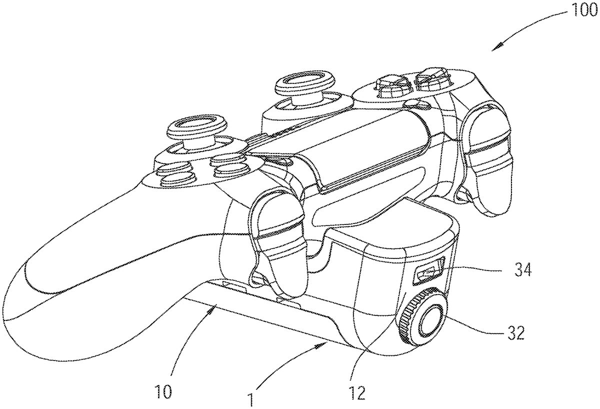
DETAILED DESCRIPTION OF THE INVENTION As shown inFIG. 1toFIG. 5, the first preferred embodiment of the present invention, an external control device1, is detachably installed on a game controller100. Referring toFIG. 2, the game controller100includes a case101, and a control circuit102, a first adapter103, a plurality of buttons104, and a storage battery105, which are provided in the case101. The control circuit102is electrically connected to the first adapter103, the buttons104, and the storage battery105, wherein the storage battery105supplies power to the control circuit102. The first adapter103is electrically connected to the storage battery105and is provided for receiving external electric power to charge the storage battery105. In this embodiment, the first adapter103is a female connector, wherein the external electric power inputting to the first adapter103charges the storage battery105through a charging circuit106; the first adapter103can also be connected to a power supply (not shown). A part of each of the buttons104is exposed to the exterior of the case101. According to a stressed state of each of the buttons104, the control circuit102generates a button signal corresponding to each of the buttons104. The button signal includes a button information which represents the stressed state of the corresponding button. The button signal can be wirelessly encoded with a specific communication protocol, and then be sent to a game console corresponding to the game controller, e.g., PS4. Or alternatively, the button signal can be output through the first adapter103in a wired way. Each of the buttons104is not limited to a concrete button, and can be a virtual button displayed on a touch screen. The external control device1includes a casing10, a second adapter18, a clamping member20, a conversion circuit26, a battery28, and a mode selector32. In this embodiment, the casing10is elongated, and has a front end12and a rear end14. A recess16is recessed from the top between the front end12and ...
DETAILED DESCRIPTION OF THE INVENTION
As shown inFIG. 1toFIG. 5, the first preferred embodiment of the present invention, an external control device1, is detachably installed on a game controller100.
Referring toFIG. 2, the game controller100includes a case101, and a control circuit102, a first adapter103, a plurality of buttons104, and a storage battery105, which are provided in the case101. The control circuit102is electrically connected to the first adapter103, the buttons104, and the storage battery105, wherein the storage battery105supplies power to the control circuit102. The first adapter103is electrically connected to the storage battery105and is provided for receiving external electric power to charge the storage battery105. In this embodiment, the first adapter103is a female connector, wherein the external electric power inputting to the first adapter103charges the storage battery105through a charging circuit106; the first adapter103can also be connected to a power supply (not shown). A part of each of the buttons104is exposed to the exterior of the case101. According to a stressed state of each of the buttons104, the control circuit102generates a button signal corresponding to each of the buttons104. The button signal includes a button information which represents the stressed state of the corresponding button. The button signal can be wirelessly encoded with a specific communication protocol, and then be sent to a game console corresponding to the game controller, e.g., PS4. Or alternatively, the button signal can be output through the first adapter103in a wired way. Each of the buttons104is not limited to a concrete button, and can be a virtual button displayed on a touch screen.
The external control device1includes a casing10, a second adapter18, a clamping member20, a conversion circuit26, a battery28, and a mode selector32. In this embodiment, the casing10is elongated, and has a front end12and a rear end14. A recess16is recessed from the top between the front end12and the rear end14, and has a recess wall162back to the front end12. The second adapter18is provided on the casing10, and is a male connector. The second adapter18protrudes from the recess wall162of the recess16and stretches to the rear end14. The second adapter18is provided to be inserted by the first adapter103of the game controller100, which makes the first adapter103and the second adapter18connected.
The clamping member20is connected to the casing10. In this embodiment, the clamping member20is detachably connected to the rear end of the casing10. The clamping member20has a stop portion22which is opposite to the recess wall162of the recess16of the casing10. Moreover, the stop portion22is a slanted plate which stretches above the recess16. The stop portion22is provided to clamp the case101of the game controller100along with the recess wall162. More specifically, the clamping member20has a joint portion which has a perforation242, and the rear end14of the casing10has a screw hole142. The clamping member20is fixed to the casing10by a screw S which passes through the perforation242of the joint portion24and then is fastened to the screw hole142, wherein the head Si of the screw S abuts against the joint portion24, so that the axis of the screw S is parallel to the stretching direction of the second adapter18. Thus, the distance between the stop portion22and the recess wall162can be adjusted by screwing in or screwing off the screw, so as to install the external control device1on the bottom of the case of the game controller, or to detach the external control device1from the game controller100.
The conversion circuit26is provided in the casing10, and is electrically connected to the second adapter18. After the second adapter18and the first adapter103are connected, the conversion circuit26is electrically connected to the control circuit102through the second adapter18and the first adapter103. Furthermore, the conversion circuit26sends a request command to request the control circuit102to output the button signal through the first adapter103in a wired way, instead of outputting the button signal wirelessly. After any of the buttons104of the game controller100is pressed, the control circuit102sends the button signal corresponding to the pressed button104to the conversion circuit26. After the conversion circuit26receives the button signal which is output from the control circuit102, the conversion circuit26converts the button signal into a pre-formatted wireless signal, and sends out the pre-formatted wireless signal through a wireless signal transmitting circuit30. The pre-formatted wireless signal corresponds to another type of game console, e.g., XBOX, PC, Nintendo SWITCH, smart phone, or tablet.
The battery28is provided in the casing10, and is electrically connected to the conversion circuit26and the second adapter18. The battery28is provided to supply power to the conversion circuit26for operation. In addition, the power of the battery28is output through the second adapter18. After the second adapter18is connected to the first adapter103, the power of the battery28, which is output through the second adapter18, forms the external electric power for charging the storage battery105of the game controller100.
In order to enable the conversion circuit26to output wireless signals corresponding to different game consoles, the mode selector32is provided sat the front end of the casing10, and is electrically connected to the conversion circuit26. The mode selector32outputs one of a plurality of different selection signals upon users' operation, wherein each of the selection signals corresponds to one type of game consoles, e.g., PS4, XBOX one, PC, Nintendo SWITCH, smart phone, or tablet. The mode selector32can be a rotary switch or an encoder. A memory262is provided in the conversion circuit26and is electrically connected to the conversion circuit26for storing a plurality of types of encode data, wherein each of the encode data corresponds to the communication protocol of one type of the game consoles. According to one of the selection signals which is output from the mode selector32, the conversion circuit26selects one of the encode data, and then according to the selected encode data, the conversion circuit26encodes and converts the received button signal into the pre-formatted wireless signal of one of the game consoles. In this way, players can select one of the game consoles they want to control through the mode selector32, and accordingly, the conversion circuit26can encode and convert the corresponding button signal into wireless signal, and then send the wireless signal to the game console they want to control. Practically, the memory262can also be independent of the conversion circuit26, and is electrically connected to the conversion circuit26.
In order to allow the battery of the external control device1to be repeatedly used, the battery of the external control device1of this embodiment is a storage battery. In addition, the external control device1includes a power source adapter34which is a female connector and provided at the front end12of the casing10. The power source adapter34is provided for being inserted by an exterior power supply so as to receive the power from the outside as well as to charge the battery28through the charging circuit36.
In this way, the external control device1in this embodiment can convert the button signal of the game controller into the wireless signal corresponding to another different game console, and provide additional power to the storage battery105of the game controller100. The game controller100and the external control device1form a game control device.
Practically, it is not necessary to install the battery28in the external control device. For example, the storage battery105inside the game controller100can supply power to the external control device.
As shown inFIG. 6, the second embodiment, an external control device2, has a structure that is substantially the same as the first embodiment. The difference between the two embodiments is that the external control device2doesn't include the clamping member. In the second embodiment, after the second adapter18and the first adapter103are connected, the recess wall162of the recess16of the casing10abuts against the case101of the game controller100.
As shown inFIG. 7, the third embodiment, an external control device3, has a structure that is substantially the same as the first embodiment. The difference between the two embodiments is that the clamping member40in the third embodiment is movable relative to a recess wall484aof a recess484of a casing48, and can move between a first position P1and a second position P2. When the clamping member40is located in the first position P1, the stop portion422and the recess wall484ahold the case101of the game controller100together so as to fix the external control device3to the case101of the game controller100. When the clamping member40is located in the second position P2, the stop portion422is spaced from the case101so as to install the external control device3on the case of the game controller100, or to detach the external control device3from the case of the game controller100.
More specifically, the casing48in this embodiment has a penetration hole482; the clamping member40includes a clamping piece42and a shaft rod44. The clamping piece42has a stop portion422and a joint portion424, wherein the joint portion424has a perforation424awhich corresponds to the penetration hole482. A rod body442of the shaft rod44passes through the perforation424aof the clamping piece42as well as the penetration hole482of the casing48so as to stick in the casing48. A head at the outer end of the shaft rod44abuts against the joint portion424of the clamping piece42, while the shaft rod44includes a block portion446at the inner end thereof. Additionally, a return spring46is fitted around the rod body442of the shaft rod44, wherein an end of the return spring46abuts against the block portion of the shaft rod44, while the other end of the return spring46abuts against the inner wall of the casing48. By this design, when the clamping member40is pulled by an external force and located in the second position P2(as shown inFIG. 8), the return spring46is compressed. At this time, the external control device3can be installed on or be detached from the case101of the game controller100. After the external force is removed, the return spring46drives the clamping member40back to the first position P1so as to fix the external control device3to the case of the game controller.
As illustrated inFIG. 9andFIG. 10, the fourth embodiment, an external control device4, has a structure that is substantially the same as the first embodiment. The difference between the two embodiments is that the screw hole502of the casing in the fourth embodiment is located between the recess504and the rear end506, and faces up. The joint portion522of the clamping member52is located above the screw hole502. By this design, a screw S can also pass through the perforation522aof the joint portion522, and then be fastened to the screw hole502, so as to fix the clamping member52to the casing50.
Moreover, the clamping member52in this embodiment includes two convex blocks, a first convex block524and a second convex block526, which are connected to the stop portion528and stretch to the recess wall504aof the recess504. The first convex block524is cuboid, while the second convex block526is a cylinder. The first convex block524and the second convex block526are provided for inserting holes on a game controller, such as charging or headphone jack, or alternatively, for abutting against the case of a game controller. By this structure, the case of a game controller can be confined by any of the convex blocks so that the external control device4can be fixed to the case of the game controller. Of course, the number of the convex blocks can be at least one.
From the above, the external control device is able to convert the button signal of the game controller into the wireless signal which corresponds to another game console. Thus, a player can operate the habitual game controller to play games with different game consoles, which makes the operation in the games easier. Furthermore, the battery of the external control device can be the external electric power to charge the storage battery of the game controller for longer battery life. Even if the storage battery is aging, the battery of the external control device can supply power to the storage battery, instead of replacing the storage battery or buying another game controller.
The external control device of each of the embodiments abovementioned is independent of the game controller, while the external control device and the game controller are connected to form the game control device. Another game control device will describe later, which integrates the game controller with the external control device.
As shown inFIG. 11andFIG. 12, the fifth embodiment, a game control device200, is based on the first embodiment, and also includes a case101, a control circuit102, a first adapter103, a plurality of buttons104, a storage battery105, and a charging circuit106. The difference between the two embodiments is that the game control device200further includes a mode selector60, a conversion circuit, a memory, and a wireless signal transmitting circuit.
The mode selector60is provided on the case101for players to operate so as to send one of a plurality of selection signals. The memory64is provided in the case101to store a plurality of encode data. In this embodiment, the memory64is independent of the conversion circuit62, but this is not a limitation of the present invention. The memory64can also be integrated with the conversion circuit62or the control circuit102.
The conversion circuit62is provided in the case101, and is electrically connected to the control circuit102, the mode selector60, and the memory64. The conversion circuit62receives a button signal which corresponds to any of the buttons104from the control circuit102, and selects one of the encode data in the memory64according to one of the selection signals output from the mode selector60, and then encodes and converts the received button signal into a pre-formatted wireless signal according to the selected encode data, and finally sends the pre-formatted wireless signal through the wireless signal transmitting circuit66.
The power required by the mode selector60, the conversion circuit, the memory, and the wireless signal transmitting circuit can be supplied by the storage battery105.
From the above, the game control device200can also send wireless signals corresponding to different game consoles.
Practically, the control circuit102, the memory64and the conversion circuit62can be integrated into a circuit or a processor.
The embodiments described above are only preferred embodiments of the present invention. All equivalent structures which employ the concepts disclosed in this specification and the appended claims should fall within the scope of the present invention.
Claims
- An external control device for a game controller which comprises a control circuit, a first adapter, and a plurality of buttons, wherein the control circuit is electrically connected to the first adapter and the plurality of buttons;according to a stressed state of each of the buttons, the control circuit generates a button signal corresponding to each of the buttons;the external control device comprises: a casing;a second adapter which is provided on the casing for being connected to the first adapter;a mode selector provided on the casing for users to operate so as to send one of a plurality of selection signals which are different;a memory provided in the casing for storing a plurality of encoded data;and a conversion circuit which is provided in the casing and electrically connected to the second adapter, the mode selector, and the memory, wherein the conversion circuit is electrically connected to the control circuit through the first adapter and the second adapter so as to receive the button signal corresponding to any of the buttons from the control circuit;according to one of the selection signals sent by the mode selector, the conversion circuit selects one of the encoded data, and then encodes and converts the button signal which is received into a pre-formatted wireless signal according to the encoded data which is selected, and finally sends the pre-formatted wireless signal through a wireless signal transmitting circuit.
- The external control device of claim 1 , further comprising a battery provided in the casing, wherein the battery is electrically connected to the conversion circuit and the second adapter;the battery supplies power to the conversion circuit;the power of the battery is output through the second adapter, and forms an external electric power for charging a storage battery in the game controller.
- The external control device of claim 1 , wherein the casing has a recess;after the second adapter and the first adapter are connected, a recess wall of the recess abuts against a case of the game controller.
- The external control device of claim 1 , further comprising a clamping member, wherein the casing has a recess which has a recess wall;the second adapter protrudes from the recess wall;the clamping member is connected to the casing, and has a stop portion which is opposite to the recess wall;the stop portion and the recess wall clamp a case of the game controller together.
- The external control device of claim 4 , wherein the clamping member is detachably connected to the casing.
- The external control device of claim 4 , wherein the clamping member has a joint portion which has a perforation;the casing has a screw hole thereon;the clamping member is fixed to the casing through a screw which passes the perforation of the joint portion and is fastened to the screw hole, wherein a head of the screw abuts against the joint portion.
- The external control device of claim 6 , wherein the clamping member comprises at least a convex block;the at least a convex block is connected to the stop portion, and stretches to the recess wall.
- The external control device of claim 6 , wherein an axis of the screw is parallel to a stretching direction of the second adapter.
- The external control device of claim 4 , wherein the clamping member is movable relative to the recess wall;the clamping member can move between a first position and a second position;when the clamping member is located in the first position, the stop portion and the recess wall hold the case of the game controller together;when the clamping member is located in the second position, the stop portion is spaced from the case.
- The external control device of claim 9 , wherein the casing has a penetration hole;the clamping member comprises a shaft rod passing through the penetration hole to stick in the casing;a return spring is fitted around the shaft rod;when the clamping member is pulled by an external force and located in the second position, the return spring is compressed;after the external force is removed, the return spring drives the clamping member to the first position.
- The external control device of claim 1 , further comprising a power source adapter which is electrically connected to the battery, wherein the battery is a storage battery;the power source adapter receives a power to charge the battery.
Disclaimer: Data collected from the USPTO and may be malformed, incomplete, and/or otherwise inaccurate.