U.S. Pat. No. 11,097,758
SYSTEM AND METHOD FOR A VIDEO GAME STORAGE PORTABILITY CART
Issue DateMarch 1, 2021
Illustrative Figure
Abstract
A system and method for an entertainment storage portability cart that is able to securely house and run new entertainment systems as they are released utilizing customizable configurations that may be used in various locations including a hospital or a library as well as used for various E-Sport events, whereby the system provides a series of security storage cases that may be exchanged and replaced to appropriately secure any entertainment system, the security storage cases designed to prevent tampering and theft, be securely mounted to the body of the entertainment storage portability cart, allow proper ventilation to the entertainment console enclosed inside of the storage case, provide proper access points to the ports and buttons of the entertainment console, and secure the entertainment console within the case to prevent unwanted movement during transportation of the entertainment storage portability cart.
Description
DETAILED DESCRIPTION In the Summary above and in this Detailed Description, and the claims below, and in the accompanying drawings, reference is made to particular features of the invention. Where reference is made herein to a method comprising two or more defined steps, the defined steps can be carried out in any order or simultaneously (except where the context excludes that possibility), and the method can include one or more other steps which are carried out before any of the defined steps, between two of the defined steps, or after all the defined steps (except where the context excludes that possibility). “Exemplary” is used herein to mean “serving as an example, instance, or illustration.” Any aspect described in this document as “exemplary” is not necessarily to be construed as preferred or advantageous over other aspects. Throughout the drawings, like reference characters are used to designate like elements. As used herein, the term “coupled” or “coupling” may indicate a connection. The connection may be a direct or an indirect connection between one or more items. Further, the term “set” as used herein may denote one or more of any item, so a “set of items,” may indicate the presence of only one item, or may indicate more items. Thus, the term “set” may be equivalent to “one or more” as used herein. In the following detailed description, numerous specific details are set forth in order to provide a more thorough understanding of the one or more embodiments described herein. However, it will be apparent to one of ordinary skill in the art that the invention may be practiced without these specific details. In other instances, well-known features have not been described in detail to avoid unnecessarily complicating the description. The present disclosure recognizes the unsolved need for an improved system and ...
DETAILED DESCRIPTION
In the Summary above and in this Detailed Description, and the claims below, and in the accompanying drawings, reference is made to particular features of the invention. Where reference is made herein to a method comprising two or more defined steps, the defined steps can be carried out in any order or simultaneously (except where the context excludes that possibility), and the method can include one or more other steps which are carried out before any of the defined steps, between two of the defined steps, or after all the defined steps (except where the context excludes that possibility).
“Exemplary” is used herein to mean “serving as an example, instance, or illustration.” Any aspect described in this document as “exemplary” is not necessarily to be construed as preferred or advantageous over other aspects.
Throughout the drawings, like reference characters are used to designate like elements. As used herein, the term “coupled” or “coupling” may indicate a connection. The connection may be a direct or an indirect connection between one or more items. Further, the term “set” as used herein may denote one or more of any item, so a “set of items,” may indicate the presence of only one item, or may indicate more items. Thus, the term “set” may be equivalent to “one or more” as used herein.
In the following detailed description, numerous specific details are set forth in order to provide a more thorough understanding of the one or more embodiments described herein. However, it will be apparent to one of ordinary skill in the art that the invention may be practiced without these specific details. In other instances, well-known features have not been described in detail to avoid unnecessarily complicating the description.
The present disclosure recognizes the unsolved need for an improved system and method for an entertainment storage portability cart that is able to securely house and run new entertainment systems as they are released utilizing customizable configurations. The system may be used in various locations including a hospital or a library as well as used for various E-Sport events. The system provides a series of security storage cases that may be exchanged and replaced to appropriately secure any entertainment system. The storage case is designed to prevent tampering and theft, be securely mounted to the body of the entertainment storage portability cart, allow proper ventilation to the entertainment console enclosed inside of the storage case, provide proper access points to the ports and buttons of the entertainment console, and secure the entertainment console within the case to prevent unwanted movement during transportation of the entertainment storage portability cart.
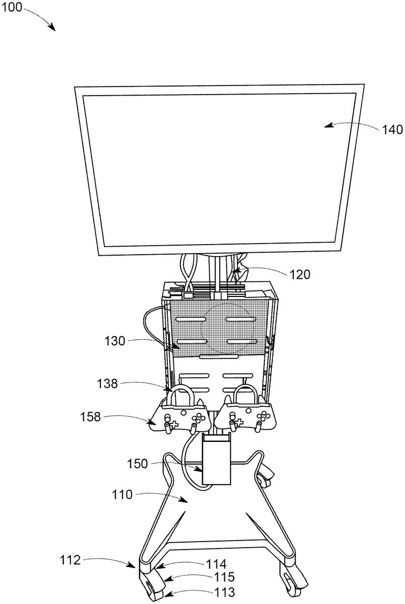
FIG. 1depicts a non-limiting embodiment of an entertainment storage portability cart100in accordance with the present invention. Entertainment storage portability cart100, in one or more embodiments of the present description, may include, without limitation, several components, such as a base110, a pole120, a storage case130, a display monitor140, and a utility box150. Entertainment storage portability cart100may be disinfected with bleach or other hospital grade disinfectants to prevent the sharing of germs between users.
Base110transfers the weight of pole120, storage case130, display monitor140, and utility box150onto a floor surface. Base110may have a rectangular shape with semicircular portions extending from corners of the rectangle. However this is non-limiting and base110may be of any shape such as a square, triangle, rhombus, parallelogram, hexagon, octagon, or any shape that may transfer the weight of the components of entertainment storage portability cart100onto the floor surface.
Wheel assemblies112, each having a wheel113and a fork114surrounding and connecting to wheel113by an axle, may be connected beneath base110to provide movement of entertainment storage portability cart100with respect to the floor surface for transportation of entertainment storage portability cart100from one location to another location. Wheel assemblies112may have a brake assembly for fortifying entertainment storage portability cart100at a specific position. The brake assembly allows the user the opportunity to lock and unlock entertainment storage portability cart100with the user's foot or hand to prevent entertainment storage portability cart100from rolling unintentionally. The brake assembly may have a brake lever115pivotally connected to fork114whereby brake lever115may have a lock or on position and an unlock or off position. When brake lever115is in the lock or ON position, brake lever115may be pushed down by the user such that brake lever115comes in contact with wheel113thus preventing wheel113from rotating. When brake lever115is in the unlock or OFF position, brake lever115may be pulled back upward by the user such that brake lever115is no longer in contact with wheel113, allowing wheels113to rotate and be mobile.
Pole120may extend vertically upward from a central cavity of base110. Pole120may be elongated in shape and formed with a tubular or polygonal cross-section such that it has a substantially hollow core. The hollow construction of pole120enables the user to route electrical and data cables therethrough to both facilitate electrical interconnection to display monitor140, an entertainment console in storage case130and to conceal the cables from view. To further facilitate such routing, one or more spaced apart apertures in pole120may provide for the ingress and egress of electrical cables being routed through the pole120.
In some embodiments, pole120may include a rear U-shaped bracket and a front shaped T-shaped flap that is removable from from a receiving element in the U-shaped bracket whereby when the T-shaped flap is removed the user may access cords in the interior of pole120. In further embodiments, the flap may be flat with protruding edges designed to fit over the U-shaped bracket. In other non-limiting embodiments, pole120may be telescopic and extendable with respect to base110.
A utility box150may be mounted to pole120and positioned near an upper surface of base110whereby the interior of utility box150may be accessed by a flip top or other door. Utility box150may have an open back end such that cords and wiring are movable from pole120into the interior of utility box150through the open back end.
The inside of utility box150may have a power strip with a plurality of female power receptacles or outlets to receive a series of male adapters from power cords of display monitor140and an entertainment console secured in storage case130as well as any appropriate cables or wires connected between display monitor140, associated electronic components located within the entertainment storage portability cart100, and any external devices located outside entertainment storage portability cart100. The power strip may have a hospital grade power cord capable of being extended outside an aperture at the bottom of utility box150to be plugged into an electrical outlet in the room where entertainment storage portability cart100is located.
In one or more non-limiting embodiments, pole120may be connected to a rechargeable battery400on the opposite side of utility box150. However this is non-limiting and rechargeable battery400may be connected to any other portion. Rechargeable battery400is of a charge, design, and capacity, to provide sufficient power to display monitor140and an entertainment system secured in storage box130while operating entertainment storage portability cart100for a set period of time. Rechargeable battery400may be connected to the power strip by any conventional means such that rechargeable battery400may be charged when the power cord of the power strip is plugged into an electrical outlet in the room where entertainment storage portability cart100is located as well as provide power to display monitor140and an entertainment system secured in storage box130.
The top end of pole120may be connected to a first end of a toggle122, as illustrated inFIG. 2, whereby pole120and toggle122are pivotally coupled together with an axle permitting rotational movement of toggle122to pole120. This connection provides a wide range of different positions and altitudes of toggle122with respect to pole120. As a result, a wide range of different positions and orientations of an attached display monitor140can be achieved. The axle is mounted in through a hole on toggle122and secured thereto with a fastener. The fastener may be any type of fasteners known in the art, including, but not limited to, any type of screw and/or nut and bolt combination. The axle has two distal ends extending out of the hole on toggle122that are supported in prongs at the top end of pole120. While the materials of construction are not critical to the novel features of pole120, toggle122, and base110, the material that is selected should provide sufficient strength and rigidity to support display monitor140and an entertainment system stored within storage case130.
Toggle122may have a mounting member123or attachment plate at a second end of toggle122for connection of toggle122to a rear surface of display monitor140at a point above a bottom of display monitor140that is sufficient to stabilize the load from display monitor140and to prevent any lateral, forward, or rearward movement of pole120. Mounting member123may be fastened to display monitor140in any of the conventional ways including bolts, screws, etc. Once fastened the pivotal connection between toggle122and pole120permits rotational movement of display monitor140with respect to pole120such that a user may orient display monitor140at multiple angles suitable for optimal viewing of the user at different elevations in the location where entertainment storage portability cart100is stationed.
Display monitor140may be a television type of monitor or display such as LED, LCD, plasma, CRT, or any type of display. For example, display monitor140may also be a computer display screen, touch screen display, video monitor, or television. Display monitor140may be digital and/or analog. Display monitor140may be a transparent surface that may receive a visual projection. Display monitor140may display a user interface on the display. Display monitor140may be of any size to provide an optimal playing experience for the user. In preferred embodiments, display monitor140is 24″ diagonally but may be any shape or size depending on the dimensions of pole120and toggle122. Display monitor140may be connected to a remote control capable of the controlling components of display monitor140.
Pole120may be connected to a handle129below display monitor140and above storage case130. Handle129may have a hook element and a grasping element extending outward from the hook element. The hook element allows the power cord of the power strip to be wound about the hook element for easy storage during transportation. The grasping element is designed to be held by the user to facilitate transportation from one location to another. The grasping element is depicted as trapezoidal in shape; however this is non-limiting and handle129may be a rectangle, circle, semicircle, hexagon, octagon, prism, horseshoe, rod, or any other suitable shape.
As discussed, entertainment storage portability cart100may utilize one or more storage cases130such that the entire entertainment storage portability cart100does not need to be replaced when a new entertainment system of different dimensions is released. Each storage case130is custom built for receiving one or more specific types of entertainment systems such as PlayStation 5 digital, PlayStation 5 disc version, Xbox Series X, Xbox Series S, Nintendo Switch, or any video game consoles or electronic devices previously released or that may be released in the future. Entertainment systems may be connected by an HDMI, coaxial, AV video, or other cord to the display monitor140for viewing of content produced by the entertainment system.FIG. 3-5illustrate some of the embodiments of cases that may be connected to and be a part of entertainment storage portability cart100, including for a PlayStation 4, Xbox One, and Nintendo Switch.
Pole120may have a bracket125or attachment plate between the top end and bottom end of pole120for connection of a storage case130to a front surface of pole120at a point below display monitor140. Bracket125may be removably fastened to a storage case130in any of the conventional ways whereby apertures133formed in storage case130allow bracket125to be universally mountable to any of a plurality of storage cases130having varied configurations. A storage case130may then be replaced with a second storage case when so desired.
As shown inFIG. 3, one embodiment of a transparent storage case130has a case body132, a lid136, and hinges134permitting rotational movement of lid136with respect to case body132. Hinges134may have a first leaf fastened to lid136and a second leaf fastened to case body132to allow lid136to be opened and closed. In other non-limiting embodiments storage case130may be opaque or translucent. Case body132, hinges134, and lid136are preferably formed from thicker durable optically clear cast acrylic sheets but may also be formed from, opaque acrylic, transparent rubber, other transparent plastic or glass. While the illustrated storage cases130are without any color, other embodiments may fabricate one or more of the components from colored transparent or opaque acrylic and acrylic with decals or etching on the surface of case body132or lid136.
A locking cam system may be placed on lid136configured to protract and retract at least one male locking component to prevent unwanted access into case body132. The male locking component is partially inserted into a latch on case body132in the locked position, preventing movement of lid136in relation to case body132, and released from the latch on case body132in the unlocked position allowing the user to remove lid136from case body132.
Case body132may have one or more stabilizing pieces139integrated within the interior of case body132such that when an entertainment system is positioned inside case body132, the entertainment system is partially suspended, such that entertainment systems do not bounce around inside case body132.
Surfaces of case body132may have one or more other different shaped apertures133to prevent obstruction of any features of an intended entertainment system that are positioned inside case body132, such as a button (i.e. power button or eject button), charging port, audio-visual ports, a headphone port, a controlling charging port, any USB-A, USB-C, Micro-USB, Lightning, USB-C or other inputs, virtual reality equipment ports, or any other components of entertainment system. Apertures133may also be formed to provide ventilation for the entertainment systems to run properly when stored within storage box130.
Accessory mounts158may be fastened to storage case130whereby accessory mounts158may be bent or flexed such that accessory mounts158will support the weight of the retained electronic products or accessories without deforming from the chosen configuration unless enough force is applied by the user. Accessory mounts158may have a hook utilized to fasten to one of the apertures in storage case130. Accessory mounts158may have a gooseneck arm extending from and removably attached to the hook on both ends. The gooseneck arm may be a spring made of a high-strength steel to provide strength and flexibility and soft galvanized iron wire that is compressed into the gaps of the spring to provide stiffness and to hold accessory mounts'158position. As such, the user connects the hook of accessory mounts158to the location chosen, thereby securing accessory mounts158in place where it is ready to retain an electronic device such as video game controller, remote control, or other accessory.
FIG. 7illustrates another embodiment of entertainment storage portability cart100with opposing storage cases130and display monitors140for multiple users to interact with.
When in use, entertainment storage portability cart100provides a customizable experience where users may switch out storage cases130designed for each entertainment system and connect the entertainment system to the display monitor140through entertainment storage portability cart100to watch the content produced by the entertainment system. Entertainment storage portability cart100may be sold separately or with various entertainment systems and respective storage cases130. A company or business may purchase entertainment storage portability cart100and storage cases130separately to accommodate various entertainment systems of patrons and other users.
The foregoing description of the invention has been presented for purposes of illustration and description and is not intended to be exhaustive or to limit the invention to the precise form disclosed. Many modifications and variations are possible in light of the above teaching. The embodiments were chosen and described to best explain the principles of the invention and its practical application to thereby enable others skilled in the art to best use the invention in various embodiments and with various modifications suited to the use contemplated.
Claims
- An entertainment storage portability cart comprising: a base;one or more support columns connected to the base;a toggle connected to the one or more support columns;one or more displays connected to the toggle;and one or more removably connected storage cases, the one or more removably connected storage cases each configured to hold one or more entertainment systems, the one or more removably connected storage cases have a series of apertures to prevent obstruction and allow airflow from the one or more entertainment systems, the one or more removably connected storage cases removably connected to the one or more support columns.
- The entertainment storage portability cart of claim 1 , further comprising wheels connected to a bottom surface of the base wherein the wheels are position lockable to prevent movement.
- The entertainment storage portability cart of claim 1 , wherein the one or more support columns has a hollow cavity to facilitate routing of cords.
- The entertainment storage portability cart of claim 3 , further comprising a utility box mounted to the one or more support columns, the utility box having an open back end such that cords are movable from the one or more support columns into an interior of the utility box through the open back end.
- The entertainment storage portability cart of claim 4 , further comprising a power strip inside of the utility box, the power strip having a plurality of female power receptacles to receive a series of male adapters from the cords.
- The entertainment storage portability cart of claim 4 , the utility box having a closeable door.
- The entertainment storage portability cart of claim 1 , further comprising a rechargeable battery of charge, design, and capacity, to provide sufficient power to the one or more displays and the one or more entertainment systems secured in storage box while operating the entertainment storage portability cart for a set period of time.
- The entertainment storage portability cart of claim 1 , wherein the toggle is in a pivotable relationship with the one or more support columns such that the one or more displays are adjustable with different orientations.
- The entertainment storage portability cart of claim 8 , the toggle having a bracket for connection to a rear surface of the one or more displays.
- The entertainment storage portability cart of claim 3 , further comprising a handle connected to the one or more support columns, the handle having a hook element configured to allow the cords to be wound about the hook element for storage during transportation.
- The entertainment storage portability cart of claim 10 , the handle having a grasping element configured to allow a user to grab the grasping element to transport the entertainment storage portability cart.
- The entertainment storage portability cart of claim 1 , wherein the one or more removably connected storage cases have a body and a lid, the lid connected to the body by one or more hinges.
- The entertainment storage portability cart of claim 12 , wherein the one or more removably connected storage cases are made of durable optically clear or opaque cast acrylic sheets.
- The entertainment storage portability cart of claim 13 , wherein the one or more removably connected storage cases have a locking system configured to prevent unwanted access into the body of the one or more removably connected storage cases.
- The entertainment storage portability cart of claim 14 , wherein the one or more removably connected storage cases have one or more stabilizing pieces integrated within an interior of the body such that when the one or more entertainment systems are positioned inside the body, the one or more entertainment systems are partially suspended.
- The entertainment storage portability cart of claim 1 , wherein the one or more removably connected storage cases are connected to one or more accessory mounts, the one or more accessory mounts having a curved arching portion to hold one or more accessories outside of the one or more removably connected storage cases.
- An entertainment storage portability cart comprising: a base;one or more support columns connected to the base;a toggle connected to the one or more support columns;one or more displays connected to the toggle;one or more removably connected storage cases, the one or more removably connected storage cases each configured to hold one or more entertainment systems, the one or more removably connected storage cases have a series of apertures through multiple surfaces to prevent obstruction and allow airflow from the one or more entertainment systems, the one or more removably connected storage cases removably connected to the one or more support columns;and one or more accessory mounts configured to hold one or more accessories.
- An entertainment storage portability cart comprising: one or more connected storage cases, the one or more connected storage cases each designed to hold one or more entertainment systems, wherein the one or more connected storage cases have a series of apertures to prevent obstruction and allow airflow from the one or more entertainment systems, wherein the one or more connected storage cases have one or more stabilizers to hold and partially suspend the one or more entertainment systems within the one or more connected storage cases, the one or more connected storage cases connected to the entertainment storage portability cart.
- The entertainment storage portability cart of claim 18 further comprising: one or more accessory mounts to hold one or more accessories outside of the one or more connected storage cases.
Disclaimer: Data collected from the USPTO and may be malformed, incomplete, and/or otherwise inaccurate.