U.S. Pat. No. 11,013,999
COMPUTER-READABLE NON-TRANSITORY STORAGE MEDIUM HAVING STORED GAME PROGRAM, INFORMATION PROCESSING SYSTEM, INFORMATION PROCESSING APPARATUS, AND INFORMATION PROCESSING METHOD FOR GENERATING A GAME IMAGE HAVING AT LEAST AN IMAGE OF A VIRTUAL SPACE AND A MAP IMAGE
AssigneeNINTENDO CO., LTD.
Issue DateMay 20, 2019
Illustrative Figure
Abstract
In an example of an information processing system, a field in a virtual space is divided into a plurality of sections, and a player character moves in units of the sections on the field. On a game screen, an image of the virtual space based on a virtual camera and a map image representing a range of at least a part of the field are displayed. When a direction of the virtual camera changes, an image representing the field rotates such that an up direction of the map image corresponds to a direction along the field in a direction of the virtual camera. In the map image, the image representing the field, an image representing the player character, images representing the sections, and an image indicating a movable range of the player character are displayed.
Description
DETAILED DESCRIPTION OF NON-LIMITING EXAMPLE EMBODIMENTS With reference to the drawings, a game system1(an example of an information processing system) according to an exemplary embodiment is described below.FIG. 1is a diagram showing an example of the game system1according to the exemplary embodiment. As shown inFIG. 1, the game system1includes a main body apparatus2, a left controller3, a right controller4, and a display device including a display screen12. It should be noted that the left controller3and the right controller4may be attachable to and detachable from the main body apparatus2. The left controller3is a controller operated with the left hand of a user. The left controller3includes a plurality of operation buttons31and an analog stick32as a direction input section. Further, the right controller4is a controller operated with the right hand of the user. The right controller4includes a plurality of operation buttons41and an analog stick42as a direction input section. Based on an operation performed using the left controller3or the right controller4, the main body apparatus2performs game processing described later and displays an image corresponding to the result of the game processing on the display screen12. Although not shown in the figures, the main body apparatus2includes a CPU for executing a game program described later, a GPU, a memory, a storage device (e.g., a non-volatile memory), and a slot into which an external storage medium is inserted. The game program is stored in the storage device built into the main body apparatus2or the external storage medium. It should be noted thatFIG. 1is a mere example of hardware for executing a game according to the exemplary embodiment described below. The game according to the exemplary embodiment may be executed by any other information processing apparatus. For example, the information processing apparatus may execute game processing, and a game image corresponding to the result of the game ...
DETAILED DESCRIPTION OF NON-LIMITING EXAMPLE EMBODIMENTS
With reference to the drawings, a game system1(an example of an information processing system) according to an exemplary embodiment is described below.FIG. 1is a diagram showing an example of the game system1according to the exemplary embodiment. As shown inFIG. 1, the game system1includes a main body apparatus2, a left controller3, a right controller4, and a display device including a display screen12. It should be noted that the left controller3and the right controller4may be attachable to and detachable from the main body apparatus2.
The left controller3is a controller operated with the left hand of a user. The left controller3includes a plurality of operation buttons31and an analog stick32as a direction input section. Further, the right controller4is a controller operated with the right hand of the user. The right controller4includes a plurality of operation buttons41and an analog stick42as a direction input section.
Based on an operation performed using the left controller3or the right controller4, the main body apparatus2performs game processing described later and displays an image corresponding to the result of the game processing on the display screen12. Although not shown in the figures, the main body apparatus2includes a CPU for executing a game program described later, a GPU, a memory, a storage device (e.g., a non-volatile memory), and a slot into which an external storage medium is inserted. The game program is stored in the storage device built into the main body apparatus2or the external storage medium.
It should be noted thatFIG. 1is a mere example of hardware for executing a game according to the exemplary embodiment described below. The game according to the exemplary embodiment may be executed by any other information processing apparatus. For example, the information processing apparatus may execute game processing, and a game image corresponding to the result of the game processing may be displayed on an external display device (e.g., a television receiver). Further, for example, the game according to the exemplary embodiment may be executed by a stationary or mobile game apparatus, a personal computer, a smartphone, a tablet terminal, or the like. Further, the game according to the exemplary embodiment may be executed by a system where a terminal and a server are connected together via a network (e.g., the Internet).
(Description of Game)
The game according to the exemplary embodiment is described below. When the game according to the exemplary embodiment is executed, a three-dimensional virtual space represented by an XYZ orthogonal coordinate system is defined within the main body apparatus2. In the virtual space, a field (a ground or the like) is set, and a player character operated by the user, an enemy character controlled by the game system1, and various other objects are placed on the field. Further, in the virtual space, a virtual camera VC (seeFIG. 9) is set.
FIG. 2is a diagram showing an example of a game image displayed on the display screen12when the game according to the exemplary embodiment is performed.
As shown inFIG. 2, in the center (an area other than a map image80at the lower right) of the display screen12, a virtual space image100based on a virtual camera VC is displayed. The virtual space image100is an image obtained by viewing the three-dimensional virtual space from the virtual camera VC and is also a three-dimensional realistic image. In the virtual space image100, a player character50operated by the user and an enemy character60controlled by the game system1are displayed.
The game according to the exemplary embodiment is a game where an own army including the player character50and an enemy army including the enemy character60fight against each other by moving on the field in the virtual space. The field in the virtual space is divided into a plurality of sections (a grid). A single section is, for example, a virtually set square with 10-meter sides. The player character50and the enemy character60move in these section (grid) units on the field.
Around the player character50, a plurality of soldier characters51are placed. The player character50and the plurality of soldier characters51form a single small group and are placed in a single section. The player character50is the leader of the small group, and the plurality of soldier characters51are characters accompanying the leader. The player character50and the plurality of soldier characters51as the small group move on the field or attack the enemy character. Thus, hereinafter, the small group including the player character50will occasionally be referred to as the “player character50”. Further, when only the player character50, which is the leader, in the small group including the characters50and51is particularly represented, the player character50will occasionally be referred to as “the player character50(the leader)”. Similarly, around the enemy character60, a plurality of soldier characters61are placed. The enemy character60and the plurality of soldier characters61form a single small group and are placed in a single section. The enemy character60and the plurality of soldier characters61as the small group move on the field or attack the player character. Thus, hereinafter, the small group including the enemy character60will be referred to as “the enemy character60”.
In the virtual space, as the own army, in addition to the player character50(the small group), a plurality of player characters (small groups) are also placed. Similarly, in the virtual space, as the enemy army, in addition to the enemy character50(the small group), a plurality of enemy characters (small groups) are also placed. The user causes the plurality of player characters (the small groups) including the player character50to move or attack the enemy character on the field in the virtual space, thereby aiming to gain ascendancy over the enemy army. In the exemplary embodiment, a turn in which the user side performs an operation and a turn in which the enemy side performs an operation are alternately repeated, whereby the game progresses. In a single turn of the user side, the user causes one or more player characters to move, or causes a player character to make an attack.
Further, in the game according to the exemplary embodiment, a plurality of fields are prepared, and in any of the plurality of fields, the own army and the enemy army fight against each other. For example, the types of the plurality of fields include a grassland field where objects such as a tree and a rock are placed, and a volcanic zone field where lava flows in places. The field may be composed of a planar surface, a curved surface, an uneven surface, or the like. The field is, for example, placed on the XZ plane set in the virtual space. Thus, a position on the field in the virtual space can be represented by X-axis and Z-axis coordinate values in the XYZ coordinate system.
FIG. 2shows the grassland field. As shown inFIG. 2, various objects are placed on the field in the virtual space. For example, a forest object65and a rock object66(seeFIG. 7) are placed. The forest object65is an object in which it is more difficult for the player character50or the enemy character60to move than usual. That is, when the movement path of the player character50is selected, and if a path through the forest object65is selected, the distance at which the player character50can move is shorter than usual. Further, in the virtual space, an object (e.g., the rock object66inFIG. 7) through which the player character50or the enemy character60cannot pass is placed.
Further, as shown inFIG. 2, on the display screen12, in addition to the player character50and the enemy character60, a cursor70is displayed. The cursor70is an indication object for the user to indicate a position or an object in the virtual space. The cursor70is, for example, placed at a position a predetermined distance away in an up direction (a Y-axis direction) of the virtual space from an indicated position on the field indicated by the cursor70.
Further, in a lower right area of the display screen12, a rectangular map image80is displayed. The map image80is an image indicating the range of at least a part of the field in the virtual space and is also an image representing a map of the field in the virtual space. The map image80is an image representing a wide range of the field also including a peripheral range not included in a field of view of the virtual camera VC. Although there are various methods for drawing the map image80, for example, the map image80as a planar object is placed in the virtual space, whereby it is possible to draw the map image80together with the virtual space image100by three-dimensional image processing. Further, it is also possible to overwrite the map image80as a two-dimensional image in a superimposed manner on the virtual space image100. Although either technique may be employed, in the following description, for convenience, an area other than the map image80will be referred to as “the virtual space image100”. Further, unless otherwise stated, in the description of the virtual space, it does not matter whether or not the map image80is placed. With reference toFIG. 3, the details of the map image80will be described.
FIG. 3is an enlarged view of the map image80inFIG. 2. As shown inFIG. 3, the map image80includes an image81representing at least a part of the field in the virtual space. In the exemplary embodiment, a field image representing the field of the virtual space is stored in advance corresponding to each of the plurality of fields. For example, a field image representing the entirety of the grassland field and a field image representing the entirety of the volcanic zone field are stored. A field image is, for example, a planar image looking down on the entirety of the field from directly above the virtual space and is also an image obtained by simplifying the field in the virtual space. The field image includes images representing objects placed in the field in the virtual space. A position on the field image and a position on the field in the virtual space correspond to each other, and the position on the field image can be represented by X-axis and Z-axis coordinate values. For convenience, a coordinate system on the field in the virtual space and a coordinate system on the field image can be the same. An image representing an object placed at a predetermined position (X, Z) on the field in the virtual space is also drawn at a predetermined position (X, Z) on the field image.
The image81inFIG. 3is an image obtained by clipping a part of the field image representing the entirety of the grassland field. Specifically, the image81is an image having a color (e.g., green) representing a grassland on the whole and is also an image including a forest icon82representing the forest object65and a rock icon83representing the rock object66(seeFIG. 7).
Further, the map image80includes a plurality of section images85(a plurality of vertical and horizontal dashed lines in the map image80) indicating the boundaries between sections set in the field, and the map image80is divided into a plurality of sections by the section images85. The section images85are drawn in a field image stored in advance, and the map image80is generated by extracting a part of the field image including the section images85in a shape suitable for display. It should be noted that the section images85may not be drawn in data of the field image, and the section images85may be superimposed on the field image later, thereby generating the map image80.
Further, the map image80includes a player character icon86representing the player character50, and an enemy character icon87representing the enemy character60. The player character icon86is placed in a section corresponding to the position of the player character50on the field in the virtual space. Further, the enemy character icon87is placed in a section corresponding to the position of the enemy character60on the field in the virtual space. The player character icon86and the enemy character icon87are represented in different colors. For example, the player character icon86is displayed in blue indicating the color of the army on the user side, and the enemy character icon87is displayed in red indicating the color of the army on the enemy side.
Further, in the game according to the exemplary embodiment, a plurality of types of characters (small groups) are prepared as player characters and enemy characters and have different properties depending on the type of the character (the small group). For example, there are a character of which the movement range is relatively small and the offensive strength is great, a character of which the movement range is small but the attack range is wide, a character of which the offensive strength is great, a character of which the defensive strength is great, and the like. An icon corresponding to the type of the character is prepared, and in the map image80, an icon corresponding to the type of the character is displayed. For example, as shown inFIG. 3, the player character50is a character handling a sword, and therefore, a sword is drawn within the player character icon86. Further, the enemy character60is a character handling a bow, and therefore, a bow is drawn within the enemy character icon87.
FIG. 4is an enlarged view of the player character icon86. As shown inFIG. 4, to the player character icon86, a physical strength display image86ais added. The physical strength display image86aindicates the value of the current physical strength parameter of the player character50. When the player character50is attacked by the enemy character60, the physical strength parameter of the player character50decreases. When the physical strength parameter reaches “0”, the player character50loses. Further, also to the enemy character icon87, a physical strength display image indicating the physical strength parameter of the enemy character60is added. Also to an icon representing another character, a similar physical strength display image is added.
It should be noted that in the following figures, for ease of illustration, the display of a physical strength display image will occasionally be omitted in the map image80.
Referring back toFIG. 3, the map image80includes a cursor icon84indicating the position of the cursor70. The cursor icon84is an icon indicating the position of the cursor70in the virtual space. Specifically, the cursor icon84is placed in a section corresponding to a position indicated by the cursor70on the field in the virtual space. For example, inFIG. 2, the position indicated by the cursor70is located in a section diagonally forward right of the section of the player character50. Thus, the cursor icon84is located at a section diagonally upward right of the player character icon86.
Here, the movement of the cursor70is described.FIG. 5is a diagram showing an example of a game image after the cursor70is moved in the right direction of the screen from the state inFIG. 2.
In the exemplary embodiment, in accordance with a direction input operation of the user (e.g., the operation of tilting the analog stick32), the cursor70moves in the virtual space, and the cursor icon84moves relative to the field image such that the input direction corresponds to a direction on the display screen. For example, the left-right direction of the analog stick32corresponds to a direction in the virtual space corresponding to the left and right on the screen, i.e., the left and right of the virtual camera in the virtual space, and the left-right direction of the map image80. The up direction of the analog stick32corresponds to the depth direction of the virtual space and the up direction of the map image80. It is intuitive that typically, the up direction of a direction input operation is defined as the up direction or the depth direction based on the manner of holding the controller. The cursor70, however, moves on the field, and therefore, as a direction in the virtual space corresponding to the up direction or the depth direction of the virtual camera, the depth direction on the field is a direction in the virtual space corresponding to the input of the up direction. In accordance with the movement of the cursor70, the virtual camera VC also moves. For example, the virtual camera VC is controlled so that the fixation point of the virtual camera VC coincides with the position indicated by the cursor70(or is near the indicated position). In other words, the virtual camera VC is controlled so that the cursor70is displayed almost in the center of the display screen12.
For example, when the right direction of the analog stick32is input in the state inFIG. 2, then as shown inFIG. 5, the cursor70and the virtual camera VC move in the right direction. Thus, in the virtual space image100, the enemy character60and the player character50move in the left direction of the screen, and are not displayed. Then, the forest object65is displayed approximately in the center in the left-right direction of the screen.
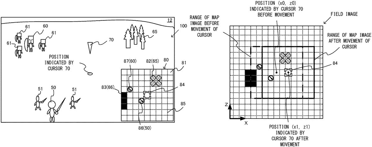
In accordance with the movement of the cursor70(the virtual camera VC), the range of the field image included in the map image80also changes.FIG. 6is a diagram showing the range of the map image before and after the movement of the cursor70.
As shown inFIG. 6, when the position indicated by the cursor70is a position (x0, z0), a predetermined rectangular area (a thick dashed line portion inFIG. 6) centered on a position (x0, z0) on the field image is extracted from the field image, and a part of the extracted field image is displayed as the map image80on the display screen12(seeFIG. 2).
Here, when the user inputs the right direction, the position indicated by the cursor70moves to (x1, z1). A predetermined area centered on the indicated position (x1, z1) after the movement is clipped, and a part of the clipped field image is displayed as the map image80on the display screen12(seeFIG. 5). Then, the cursor icon84is placed in a section corresponding to the position indicated by the cursor70. That is, the range of the field included in the map image80moves such that the cursor icon84is located at the center of the map image80.
As described above, in accordance with the movement of the cursor70(the virtual camera VC), the range of the field included in the map image80is moved, and the map image is generated by including the field in the field of view of the virtual camera VC.
It should be noted that the cursor70also moves in the same section in the virtual space. That is, the cursor70can move to any position in the virtual space. In contrast, the cursor icon84of the map image80moves in section units. Thus, even when the cursor70moves in the virtual space, but if the movement is in the same section, the cursor icon84of the map image80does not move. Here, the position indicated by the cursor70coincides with the center of the map image80. Thus, for example, when the cursor70moves in the right direction in the same section, the outer frame of the map image80slightly moves in the right direction. That is, the range of the field included in the map image80slightly moves in the right direction. Also in this case, the cursor70is located in the same section before and after the movement, and therefore, the section indicated by the cursor icon84of the map image80does not change.
It should be noted that the cursor70in the virtual space may also move in section units. Further, the position indicated by the cursor70in the virtual space and the center of the map image80may not necessarily need to coincide with each other.
Further, a terminal is defined in the field in the virtual space, and the player character50and the enemy character60are configured not to move beyond the terminal of the field. In this case, when the cursor70is present near the terminal, the center of the map image80may not need to coincide with the position indicated by the cursor70. For example, the center position of the map image80may be appropriately adjusted so that the range where the player character50and the enemy character60can move is displayed near the center of the map image80.
(Display of Movable Range Using Map Image)
Next, the display of the movable range of the player character50using the map image is described.FIG. 7is a diagram showing an example of a game image displayed when the player character50is selected by setting the cursor70to the position of the player character50.
As shown inFIG. 7, when the cursor70is at the position of the player character50, a plurality of movable range images88indicating the movable range of the player character50are displayed in the map image80. The movable range images88indicate that the player character50can move to the sections of the movable range images88. The player character50can move only once in a single turn. The player character50can move to any section within the movable range indicated by the movable range images88, while the player character50cannot move out of the movable range. Thus, to move the player character50out of the movable range indicated by the movable range images88, the user needs to move the player character50in the current turn and further move the player character50in the next turn.
The movable range of the player character50is defined based on the type of the player character50. For example, the movable range of the player character riding on a horse may be wider than the movable range of the player character50walking on foot.
Further, the movable range of the player character50may be determined based on a parameter of the player character50. For example, the movable range of the player character50may be determined based on a movement strength parameter. The movement strength parameter is a parameter representing the amount at which the player character50can move at a time. In each section on the field, a movement consumption amount to be consumed when the player character50moves is defined. For example, when the player character50moves to the section where the forest object65is placed, the movement strength parameter of the player character50decreases by the movement consumption amount set in the section. Further, the movement consumption amount defined for the forest object65is set to be larger than flatland. Further, the player character50cannot move to the section where the enemy character60is placed or the section where a landform that cannot be entered by the player character50is placed. Based on the current movement strength parameter of the player character50, the movement consumption amount set for each section, and whether or not each section can be entered, the movable range of the player character50is calculated. Then, the movable range images88are displayed in the calculated movable range.
InFIG. 7, the movable range images88are displayed in the range of a general rhomboid centered on the player character icon86. Here, in the third section in the left direction of the player character icon86, the rock icon83is placed. The player character50cannot move to the section where the rock icon83is placed. Thus, the movable range images88are not displayed in the section where the rock icon83is placed.
Further, in sections around the movable range images88, attack-possible range images89indicating the attack-possible range of the player character50are displayed. The attack-possible range images89are images indicating the range where the player character50cannot move, but can make an attack. In the map image80inFIG. 7, the attack-possible range images89are displayed in the section where the enemy character icon87is located. Thus, the player character50can attack the enemy character60. It should be noted that the attack-possible range varies depending on the type of the character. In the case of a character capable of making an attack in an adjacent section, the attack-possible range images89are displayed in a section adjacent to the movable range images88. In the case of a character capable of making an attack in a distant section, the attack-possible range images89are further displayed in a wider range.
Further, images of the sections where the enemy character60can make an attack in a turn of the enemy side may be further displayed. Regarding all the enemy characters60or those specified among the enemy characters60, based on the movement strength parameter, the landform, other placed characters, the attack firing range, and the like, all the sections where the enemy characters60can make an attack in a single action are calculated, and dangerous range images can be displayed in the map image80such that all the calculated sections are a dangerous range. However, taking into account that it is difficult to view the map in a case where the range is wide, only when the user gives a display instruction, the dangerous range images may be displayed. The dangerous range images are thus displayed, whereby, when the user moves the player character50, it is easy to consider moving the player character50to the position where the player character50is not attacked in a turn of the enemy side, or moving the player character50to the position where the player character50is attacked in an advantageous state.
Further, as shown inFIG. 7, in the virtual space image100, a range object71indicating the movable range of the player character50is displayed. The range object71indicates the range where the player character50can move. The range object71is placed on the field in the virtual space. The range object71corresponds to the outer edge of the movable range composed of the plurality of movable range images88in the map image80. It should be noted that also in the virtual space image100, in addition to the range object71indicating the movable range, images indicating the attack-possible range may be displayed.
Here, the movable range images88and the attack-possible range images89in the map image80are displayed when the cursor70moves to the position of the player character50(i.e., when the cursor70enters the section where the player character50is located). On the other hand, the range object71in the virtual space image100is displayed when a selection button (e.g., the operation buttons41) is pressed by the user in a case where the cursor70is at the position of the player character50.
It should be noted that the range object71in the virtual space image100may also be displayed when the cursor70enters the section where the player character50is located. Alternatively, the movable range images88and the attack-possible range images89in the map image80may be displayed when the cursor70is in the section where the player character50is located, and the selection button is pressed.
Further, in the map image80, in addition to the movable range and the attack-possible range of the player character50, movable range images88indicating the movable range of the enemy character60and attack-possible range images89indicating the attack-possible range of the enemy character60may be displayed. Similarly, in the virtual space image100, an image indicating the movable range of the enemy character60and an image indicating the attack-possible range of the enemy character60may be displayed.
Further, an image of the range object71in the virtual space image100may not be a line image as shown inFIG. 7, but may be an image (a plane image) indicating each section on the field similarly to the movable range images88in the map image80. The same applies to an image indicating the attack-possible range in the virtual space image100.
Further, if the selection button (e.g., the operation buttons41) is pressed by the user when the cursor70is at the position of the player character50, the player character50(the leader) is displayed to be relatively large in the virtual space image100. For example, when the player selects the player character50(presses the selection button) using the cursor70, the plurality of soldier characters51are reduced. That is, before the player selects the player character50using the cursor70, the player character50(the leader) and the plurality of soldier characters51are of almost the same sizes, or the player character50(the leader) is slightly larger than the plurality of soldier characters51. When the player selects the player character50using the cursor70, the plurality of soldier characters51are reduced, and the player character50(the leader) is displayed to be larger than the plurality of soldier characters51. In other words, the differences in size between the player character50(the leader) and the plurality of soldier characters51when the player character50is selected are greater than the differences in size between the player character50(the leader) and the plurality of soldier characters51when the player character50is not selected. It should be noted that when the player selects the player character50using the cursor70, the plurality of soldier characters51may not be reduced, but the player character50(the leader) may be enlarged. When the player character50is selected, the player character50(the leader) is displayed to be larger than the plurality of soldier characters51, whereby it is easy for the player to recognize that the player character50is selected.
Further, in the exemplary embodiment, in the state where the virtual space image100and the map image80are displayed, the direction of the line of sight of the virtual camera VC can be set to a first direction in which the field in the virtual space is looked down on from obliquely above, and a second direction in which the field in the virtual space is viewed from the side. For example, the first direction may be the direction in which the direction of the line of sight of the virtual camera VC is 45 degrees to the field. Further, the second direction may be the direction in which the direction of the line of sight of the virtual camera VC is 10 to 20 degrees to the field. When the direction of the line of sight of the virtual camera VC is the first direction, the player character50(the leader) is larger than the plurality of soldier characters51. On the other hand, when the direction of the line of sight of the virtual camera VC is the second direction, the player character50(the leader) is larger than the plurality of soldier characters51, but the differences in size between the player character50(the leader) and the plurality of soldier characters51are smaller than in a case where the direction of the line of sight of the virtual camera VC is the first direction. Consequently, when the field is looked down on from above, it is possible to make the character as the leader for the player easily distinguishable.
Here, in the virtual space, an information object indicating information regarding the name, the physical strength parameter, and the like of each character may be placed.FIG. 8is a diagram showing an example of the information object indicating the information regarding each character.
As shown inFIG. 8, an information object72indicating information regarding the player character50is placed near the player character50. The information object72is an object placed in the virtual space. When the information object72is included in the field of view of the virtual camera VC, the information object72is displayed in the virtual space image100based on the virtual camera VC. The information object72includes the name of the player character50, an image indicating the type of the player character50(the same image as the player character icon86), and a physical strength display image73. The physical strength display image73is an image indicating the physical strength parameter of the player character50. The information object72may include information regarding another parameter in addition to these pieces of information.
Further, an information object74indicating information regarding the enemy character60is also placed near the enemy character60. The information object74includes the name of the enemy character60, an image indicating the type of the enemy character60(the same image as the enemy character icon87), and a physical strength display image75. The physical strength display image75is an image indicating the physical strength parameter of the enemy character60. In addition to these pieces of information, various pieces of information may be displayed in the virtual space image100. For example, information indicating the current field, information indicating the level of the player character50, and the like may be displayed.
As described above, in the virtual space image100, an information object is displayed in a superimposed manner on the player character50, the enemy character60, or the like. The information object indicates information necessary for the user and is also information necessary for the progress of the game. However, there is a possibility that the player character50, the enemy character60, the cursor70, or the like placed in the virtual space is hidden by the information object, and it is difficult for the user to visually recognize the situation of the virtual space. In the exemplary embodiment, however, the map image80is displayed. Thus, the user can visually recognize the situation of the virtual space based on the map image80and advance the game. It should be noted that the information object may be set to be a hidden state at default and displayed in accordance with an operation of the player.
It should be noted that in the following figures, for description, the display of the information objects72and74shown inFIG. 8is omitted.
(Display of Map Image when Direction of Virtual Camera Changes)
Next, a description is given of the display of the map image when the direction of the virtual camera VC changes. First, with reference toFIG. 9, control of the virtual camera VC in the virtual space is described.FIG. 9is a diagram showing the state where the direction of the virtual camera VC changes.
As shown inFIG. 9, for the virtual camera VC, a camera coordinate system (a CxCyCz coordinate system) fixed to the virtual camera VC is set. The Cz-axis is an axis in the direction (the direction of the line of sight) of the virtual camera VC. The Cy-axis is an axis orthogonal to the Cz-axis and is also an axis in the up direction of the virtual camera VC. The Cx-axis is an axis orthogonal to the Cy-axis and the Cz-axis and is also an axis in the right direction of the virtual camera VC.
For example, when the user inputs a predetermined direction using the analog stick42, the virtual camera VC rotates about the cursor70. When the virtual camera VC is at a position P1, the game image shown inFIG. 7is displayed. At this time, for example, when the analog stick42is tilted in the left direction, the virtual camera VC rotates in the left direction by an angle corresponding to the tilt amount about a straight line passing through the position indicated by the cursor70and parallel to the Y-axis. For example, the virtual camera VC moves from the position P1immediately behind the player character50to a position P2diagonally backward right of the player character50. When the analog stick42is tilted to the right, the virtual camera VC is directed to the right and moves to the left. It should be noted that the perception of the association between the input of the stick and the direction of the virtual camera varies from individual to individual. Thus, in another example, conversely, in accordance with the input of the left, the virtual camera may be directed to the right and move to the left. Further, the user may be allowed to, by a setting, specify which association is to be used.
FIG. 10is a diagram showing an example of a game image when the virtual camera VC is at the position P2shown inFIG. 9.
As shown inFIG. 10, when the virtual camera VC is at the position P2, the enemy character60is located in the direction of the line of sight of the virtual camera VC, and the enemy character60is displayed in a center area in an upper portion of the display screen12. Further, the rock object66is located on the left side in the direction of the line of sight of the virtual camera VC, and the rock object66is displayed in a left area of the virtual space image100.
At this time, as the map image80, an image in which the entirety of the field rotates is displayed. Specifically, the field image included in the map image80rotates such that the direction along the field in the direction of the virtual camera VC corresponds to the up direction of the map image80. Thus, in the up direction of the player character icon86in the map image80, the enemy character icon87is displayed.
Here, the generation of the map image80is described.FIG. 11is a diagram illustrating the generation of the map image80when the virtual camera VC changes from the position P1to the position P2.
As shown inFIG. 11, when the virtual camera VC is at the position P1, the direction of a vector Cz′ obtained by projecting a vector Cz indicating the direction of the virtual camera VC onto the XZ plane, and the Z-axis direction of the field image coincide with each other. From this field image, a predetermined area centered on the position indicated by the cursor is clipped, thereby generating the map image80.
On the other hand, when the virtual camera VC moves to the position P2, the field image is rotated such that the direction of the vector Cz′ along the XZ plane in the direction of the line of sight of the virtual camera VC coincides with the up direction of the map image80(the up direction when the map image is displayed). For example, the angle between the vector Cz′ and a vector in the Z-axis direction is calculated, and the direction of the range of the map image relative to the field image is set based on the calculated angle. Then, a predetermined area which is centered on the position indicated by the cursor and of which the direction is changed is extracted from the field image, thereby generating the map image80rotated further than before the movement.
It should be noted that the position of the virtual camera VC continuously changes from the position P1to the position P2for a predetermined time. Thus, in the middle of the movement of the virtual camera VC from the position P1to the position P2, the middle of the state whereFIG. 7changes toFIG. 10is displayed. That is, it seems as if the display content of the map image80rotates.
Further, not only by the above method for calculating the vector Cz′, but also by another method, the up direction of the map image when the map image is displayed may correspond to the direction along the field in the direction of the virtual camera VC.
Here, the field in the virtual space may be composed not only of a complete plane, but also of an uneven surface or a partially inclined surface. Also in such a case where the field in the virtual space is not a complete plane, the entirety of the field can be regarded as a plane except for an uneven portion or an inclined portion. Thus, “the direction along the field in the direction of the virtual camera VC” is the direction along the plane in the direction of the virtual camera VC, and specifically, can be said to be the vector Cz′. Further, the cursor70can move parallel to the XZ plane inFIG. 9. However, when the height of the ground changes due to the unevenness of the landform, the height of the cursor70may change in accordance with the height of the ground when the cursor70moves.
If the left direction is further input when the virtual camera VC is at the position P2, the virtual camera VC further rotates and moves to a position P3on the right side of the player character50(seeFIG. 9).
FIG. 12is a diagram showing an example of a game image when the virtual camera VC is at the position P3shown inFIG. 9.
As shown inFIG. 12, when the virtual camera VC is at the position P3, the rock object66is located in the direction of the line of sight of the virtual camera VC. At this time, as the map image80, an image obtained by further rotating the image representing the field fromFIG. 10is displayed. Specifically, the field image included in the map image80rotates such that the up direction of the map image80corresponds to the direction along the field in the direction of the virtual camera VC. Thus, the rock icon83is displayed in the up direction of the player character icon86of the map image80.
As described above, when the direction of the virtual camera VC changes, the field image included in the map image80rotates such that the direction along the field in the direction of the virtual camera VC corresponds to the up direction of the map image. Consequently, the up direction of the map image displayed on the display screen12always coincides with the direction along the field in the direction of the virtual camera VC. Further, for example, the right direction of the virtual space image100corresponds to the right direction of the map image80, and the left direction of the virtual space image100corresponds to the left direction of the map image80. Thus, by viewing the map image80, the user can easily grasp the positional relationship between the player character50and the enemy character60on the field and the situation of the field (e.g., a battle situation).
Further, also in the state where the direction of the virtual camera VC thus changes, then in accordance with a direction input operation of the user (e.g., the operation of tilting the analog stick32), the cursor70moves in the virtual space such that the input direction and the direction on the display screen correspond to each other, and the cursor icon84moves relative to the field image. That is, regardless of the direction of the virtual camera VC, it is possible to move the cursor70and the cursor icon84in the displayed direction.
In the map image80, the movable range images88indicating the movable range of the player character50are displayed. Thus, by viewing at least the map image80, the user can easily recognize to which section the player character50can move and which enemy character60the player character50can attack, thereby advancing the game. Further, the user can advance the game by viewing the map image80and can also view the field in the virtual space from the user's desired viewpoint by changing the direction of the virtual camera. Further, the direction of the virtual camera VC and the direction of the field image included in the map image80are displayed on a single screen in conjunction with each other. Thus, the user does not need to switch the map image80and the virtual space image100and can smoothly advance the game.
Further, the player character50is displayed in a form (a group display form) in which the plurality of soldier characters51are included, and the enemy character60is also displayed in a form (a group display form) in which the plurality of soldier characters61are included. Thus, it is possible to improve appearance in a game where groups fight against each other, and increase a realistic feeling. Meanwhile, when the player character50and the enemy character60are thus displayed in the group display forms, and if the player character50and the enemy character60are adjacent to each other, for example, there is a possibility that it is difficult to distinguish whether a soldier character is a character in the group on the player character50side or a character in the group on the enemy character60side. However, even in such a case, by viewing the map image, the user can grasp the boundary between the player character50(the small group) and the enemy character60(the small group). Further, when the virtual camera VC comes so close that the player character50and the plurality of soldier characters51can be displayed, it can be difficult to grasp the surroundings due to the narrow field of view. However, also in this case, necessary information regarding the surroundings is displayed on the map image80. Thus, it is possible to grasp the surroundings. The moving direction of the cursor70is a direction on display and further operates in conjunction with a direction on the map image. Thus, by viewing the map image80, it is possible to move the cursor70even in the situation where it is difficult to view the surroundings. Thus, it is possible to pay attention to the animation of a character and the like while displaying necessary information.
(Display of Movement Path)
Next, the display of a movement path is described.FIG. 13is a diagram showing an example of a game image when the cursor70is moved in the state shown inFIG. 7.
When the user sets the cursor70to the player character50and presses the selection button (e.g., any of the plurality of operation buttons41), the player character50is selected. Alternatively, every time the user gives a predetermined instruction (e.g., presses any of the plurality of operation buttons41), one of the plurality of player characters50may be selected in order, and the cursor70may move to the position of the selected player character50. In the state where the player character50is selected, the user indicates a section as the movement destination of the player character50using the cursor70.
As shown inFIG. 13, when the cursor70is moved in the state where the player character50is selected, a path image90is displayed in the map image80. The path image90is an image indicating the path from the section before the movement of the player character50to the section as the movement destination. The path image90is an arrow image of which the starting point is the section before the movement (the section where the player character50is currently located), and the ending point is the section as the movement destination (the section where the cursor70is currently located).
Further, on the field in the virtual space, a path object76indicating the path from the section before the movement to the section as the movement destination of the player character50is placed. The path object76is an arrow object of which the starting point is the position of the player character50before the movement, and the ending point is the position of the player character50at the movement destination. The virtual space including the path object76is captured by the virtual camera VC, whereby the path object76is displayed on the virtual space image100.
Then, when the cursor70indicates the section as the movement destination, and if a determination button for finalizing the movement or the attack (e.g., any of the operation buttons41) is pressed, the player character50moves to the section indicated by the cursor70. Further, when the enemy character60is present in the section indicated by the cursor70, the player character50attacks the enemy character60. In the example ofFIG. 13, the cursor70indicates a section to the right of the enemy character60. Thus, when the determination button is pressed in this state, the player character50moves to the section to the right of the enemy character60. Then, it is possible to further give an instruction to attack the enemy character60. When the instruction is given, the player character50attacks the enemy character60. If the determination button is pressed when the section of the enemy character60is directly indicated using the cursor70, the player character50moves close to the enemy character60(a section within the movable range) and immediately attacks the enemy character60. It should be noted that in the virtual space image100, the range object71may be displayed, while the path object76may not be displayed.
InFIG. 13, when the player character50is selected, and the cursor70moves before the determination button is pressed, only the cursor70moves in the virtual space image100. When the player character50is selected, and the cursor70moves before the determination button is pressed, the player character50may also move together with the cursor70in the virtual space image100.
FIG. 14is a diagram showing an example of the state where, when the player character50is selected, the player character50moves in the virtual space in accordance with a movement operation of the player.FIG. 15is a diagram showing an example of an image when the determination button for finalizing the movement or the attack is pressed in a case where the image shown inFIG. 14is displayed.
As shown inFIG. 14, after the player selects the player character50and before the player presses the determination button, the player character50(the leader) and the cursor70freely move within the movable range in the virtual space image100, for example, in accordance with an operation on the analog stick32. The virtual camera VC moves in the virtual space in accordance with the movements of the cursor70and the player character50(the leader). Further, the plurality of soldier characters51move following the movement of the player character50(the leader). While the player character50(the leader) moves, the plurality of soldier characters51move slightly behind the player character50(the leader) by following the player character50(the leader).
Before the determination button is pressed, and even when the player character50moves in the virtual space image100, the player character icon86does not move in the map image80. That is, until the operation of finalizing the movement is performed, the position of the player character icon86in the map image80does not change. In the map image80, the path image90is displayed. The path image90indicates the path from the section before the movement (the current position of the player character icon86) to the section as the movement destination (the section where the cursor icon84is located; the section corresponding to the position of the player character50in the current virtual space image100).
It should be noted that when a cancellation button indicating the cancellation of the movement is pressed in the state where the image indicated inFIG. 14is displayed, then in the virtual space image100, the player character50and the cursor70return to a predetermined position in the section before the movement (e.g., the center of the section). In this case, the player character50(the leader) and the cursor70instantly return to the predetermined position in the section before the movement. In accordance with the movements of the player character50and the cursor70, the fixation point of the virtual camera VC also instantly returns to the previous position. Thus, in the virtual space image100, a scene corresponding to the section as the movement destination instantly switches to a scene corresponding to the section before the movement. Meanwhile, the plurality of soldier characters51return into the section before the movement behind the player character50(the leader) by following the player character50(the leader). Even before the plurality of soldier characters51completely return into the section before the movement, the player character50(the leader) can move in accordance with an operation on the analog stick32. That is, even while the plurality of soldier characters51move toward the section before the movement in accordance with the pressing of the cancellation button, the player character50(the leader) starts moving from the predetermined position in the section before the movement in accordance with an operation on the analog stick32. That is, the plurality of soldier characters51always continue to move from the current position to a predetermined position relative to the player character50(the leader).
The plurality of soldier characters51continue to move following the player character50(the leader). Thus, even when the player character50(the leader) and the fixation point of the virtual camera VC instantly return to the previous position in accordance with the pressing of the cancellation button, it is possible to avoid giving the player a sense of interruption of the scene. Further, the plurality of soldier characters51automatically move following the player character50(the leader). Thus, the player does not need to control the movement of the plurality of soldier characters51. It is possible to efficiently advance the game.
When the determination button for finalizing the movement or the attack is pressed in the state shown inFIG. 14, the image shown inFIG. 15is displayed. As shown inFIG. 15, at the timing when the determination button is pressed, the player character50(the leader) moves to the predetermined position in the section (e.g., the center in the section) where the player character50(the leader) is currently located in the virtual space image100. InFIG. 15, a position70′ indicates the position indicated by the cursor, i.e., the position of the player character50(the leader), immediately before the determination button is pressed. As described above, before the determination button is pressed, the cursor70and the player character50(the leader) can move to any position in the section. There is a case where the player character50(the leader) immediately before the determination button is pressed is placed at a position different from the predetermined position in the section where the player character50(the leader) is located. In this case, at the timing when the determination button is pressed, the cursor70and the player character50(the leader) move to the predetermined position in the section. The plurality of soldier characters51also move following the movement of the player character50(the leader). Further, in the map image80, the player character icon86moves to the section as the movement destination (the section where the cursor icon84is located; the section indicated by the end of the arrow of the path image90) in accordance with the pressing of the determination button. It should be noted that at the time when the determination button for finalizing the movement or the attack is pressed, the position of the player character50(the leader) may not be moved, and the position of the player character50(the leader) may be moved to the predetermined position in the section after a battle, when cancellation is made, when the viewpoint is switched, or the like.
Consequently, the movement of the player character50in section units is completed. It should be noted that when the determination button is pressed, the selection of the player character50is canceled. Thus, in the map image80, the movable range images88and the attack-possible range images89are hidden.
As described above, after the player character50is selected using the cursor70and before the determination button is pressed, the cursor70and the player character50may be able to freely move within the movable range in accordance with an operation of the player. Then, in accordance with the pressing of the determination button, the player character50may move to a predetermined position in the section where the player character50is currently located, and the movement of the player character50in section units may be completed. It can be said that the positions of the cursor70and the player character50before the determination button is pressed are an indicated position indicating the section as the movement destination of the player character50to be finalized when the determination button is pressed. That is, it can be said that to freely move the player character50within the movable range of the player character50in the virtual space image100is to indicate the section as the movement destination of the player character50. Thus, when the player character50moves in the virtual space image100before the determination button is pressed, the cursor70may not need to be displayed. In this case, the cursor icon84may not need to be displayed in the map image80, either. Even when the cursor icon84is not displayed in the map image80, the player can recognize the section before the movement and the section as the movement destination based on the path image90.
In such a movement form, it is possible to proceed to the next game scene (e.g., an attack on the enemy character60, the movement of the enemy character60, or the like) more quickly than in a case where only the cursor70moves before the pressing of the determination button as described with reference toFIG. 13. Further, when only the cursor70moves before the pressing of the determination button, and the player character50moves in accordance with the pressing of the determination button, it is necessary to determine in what path the player character50is moved from the starting point to the ending point. For example, when there is an obstacle between the starting point and the ending point, it is necessary to determine a path making a detour around the obstacle. Further, when the player character50is linearly moved from the starting point to the ending point without making such a detour, and an obstacle is present in the path from the starting point to the ending point, this can result in an unnatural appearance such as the player character50moving through the obstacle or the virtual camera VC hitting the obstacle. However, as shown inFIGS. 14 and 15, also in the game based on the premise that the player character50moves in section units in the field, then by freely moving the player character50before the determination button is pressed, it is possible to reduce such an unnatural appearance.
Further, even when the player character50is moved before the pressing of the determination button, the player character icon86does not move in the map image80, and the cursor icon84and the path image90are also displayed. Thus, the player can grasp from where to where the player character50is to move.
As described above, in the exemplary embodiment, on the display screen12, the map image80is displayed in addition to the virtual space image100. The player character50moves in section (grid) units obtained by dividing the field in the virtual space into predetermined areas. The map image80includes the image representing the field in the virtual space, the player character icon86representing the player character50, the section images85indicating the sections set in the field, and the movable range images88indicating the movable range of the player character50regarding the movement in section units. Since the map image including the image representing the field divided by the section images, the player character icon, and the movable range image is displayed, the user can advance the game by viewing at least the map image80.
The movement of the player character50in section units as used herein refers to, for example, a movement to a final movement destination in a case where the operation of finalizing the movement is performed. If the final movement is made in section units, then before the final movement is made, the player character50may be able to freely move in the field as shown inFIG. 14. For example, before a finalization operation is performed, the player character50may be able to move to any position in the movable range, and in accordance with the fact that the finalization operation is performed, the movement of the player character50in section units may be finalized.
Further, when the direction of the virtual camera VC changes, the image representing the field included in the map image80rotates such that the up direction of the map image80when the map image80is displayed on the display screen12corresponds to the direction along the field in the direction of the virtual camera VC. Consequently, based on the map image80, the user can easily grasp the positional relationship between the player character50and the enemy character60or a battle situation.
Further, while the virtual space image100and the map image80are displayed on a single screen, the movable range images88regarding the movement in section units are displayed in the map image80, and further, the direction of the line of sight of the virtual camera VC and the up direction of the map image are caused to correspond to each other, thereby obtaining the following effect. That is, by viewing at least the map image80, the user can advance a game where the player character50is moved in section units. Further, by viewing the virtual space image100on the same screen, the user can view the more detailed situation of the virtual space. Further, since the virtual space image100and the map image80are displayed on a single screen, it is not necessary to switch screens, and it is possible to smoothly advance the game.
It should be noted that in the exemplary embodiment, in addition to the above mode where the virtual space image100and the map image80are displayed, the game can also be executed in the mode where the map image80is not displayed. Specifically, the virtual camera VC is zoomed in, the game image including the virtual space image100and the map image80shown inFIG. 7or the like is displayed. When the virtual camera VC is zoomed out, only an image of the virtual space is displayed.
FIG. 16is a diagram showing an example of a game image when the virtual camera VC is zoomed out at the position of the virtual camera VC shown inFIG. 7.
In accordance with an operation of the user, a zoom-in mode shown inFIG. 7switches to a zoom-out mode shown inFIG. 16. As shown inFIG. 16, when the virtual camera VC is zoomed out, an image based on the virtual camera VC that is also an image of the range of the field wider than when the virtual camera VC is zoomed in is displayed on the display screen12. Meanwhile, the map image80is not displayed. Further, when the virtual camera VC is zoomed out, the soldier characters51around the player character50are not displayed. Similarly, the soldier characters61around the enemy character60are not displayed, either. Further, on the field in the virtual space, a plurality of range objects77indicating the movable range of the player character50are placed. Each range object77indicates a section where the player character50can move. When the user moves the player character50on this screen, the user sets the cursor70to the player character50and presses the selection button. Then, the user moves the cursor70to a section as the movement destination and presses the determination button. As a result, the player character50moves to the section indicated by the cursor70. Further, a plurality of attack range objects78indicating the attack-possible range of the player character50are displayed. To cause the player character50to attack the enemy character60, the user sets the cursor70to the player character50and presses the selection button. Then, the user moves the cursor70to the section where the enemy character60is located. Then, the user presses the determination button. As a result, the player character50moves close to the enemy character60and attacks the enemy character60.
It should be noted that when the virtual camera VC is zoomed out, the range object71(the line object) as inFIG. 7may be displayed instead of the range objects77.
Further, in accordance with an operation of the user, the zoom-in mode shown inFIG. 7may instantly switch to the zoom-out mode shown inFIG. 16. Further, the zoom-in mode shown inFIG. 7may gradually change to the zoom-out mode shown inFIG. 16, the map image may be displayed until immediately before the state shown inFIG. 16, and the map image may not be displayed in the state shown inFIG. 16.
(Details of Game Processing)
Next, an example of game processing performed by the main body apparatus2is specifically described. First, data stored in the main body apparatus2is described.
FIG. 17is a diagram showing an example of data stored in the memory of the main body apparatus2. As shown inFIG. 17, the main body apparatus2stores a game program, player character data, enemy character data, virtual camera data, cursor data, field image data, map image data, and game image data.
The game program is a program for executing the game according to the exemplary embodiment. The game program is stored in the storage device of the main body apparatus2or the external storage medium. When the game according to the exemplary embodiment is started, the game program is loaded into the memory. The player character data is data regarding the player character50(and the other player characters). The player character data includes data regarding the position on the field, the physical strength parameter, the movement strength parameter, the type, the offensive strength, and the like of the player character50. The enemy character data is data regarding the enemy character60(and the other enemy characters). The enemy character data includes data regarding the position on the field, the physical strength parameter, the movement strength parameter, the type, the offensive strength, and the like of the enemy character60.
The virtual camera data is data related to the virtual camera VC and includes information such as the position in the virtual space, the orientation including the direction of the line of sight, and the angle of view regarding zooming in or zooming out of the virtual camera VC.
The cursor data is data regarding the cursor70and includes information regarding an indicated position indicated by the cursor70, information indicating whether or not a character (the player character50or the like) is selected, and the like.
The field image data is data indicating the field image. The field image is an image prepared in advance and is also a planar image obtained by viewing the field from directly above the virtual space (e.g., an image of the simplified field). It should be noted that as the field image, another image may be prepared in advance, or an image obtained by capturing the field in the virtual space from above (e.g., directly above) the virtual space with a virtual camera may be used.
The map image data is data necessary to display the map image80. Further, the game image data is data indicating a game image and is also an image including an image generated based on the virtual camera VC and the map image80.
Next, a description is given of the details of the game processing performed by the main body apparatus2.FIG. 18is a flow chart showing an example of the game processing performed by the main body apparatus2. The processing shown inFIG. 18is performed by the CPU of the main body apparatus2executing the game program.
As shown inFIG. 18, when the execution of the game program is started, an initial process is performed (step S100). In the initial process, the virtual space is defined, and various objects (the player character50, the enemy character60, the cursor70, the information objects, and the like) are placed on the field in the virtual space, and the virtual camera VC is placed.
Next, the main body apparatus2acquires operation data indicating an operation performed on the left controller3or the right controller4(step S101). Next, the main body apparatus2performs a cursor control process (step S102). For example, based on the acquired operation data, the main body apparatus2determines whether or not a movement operation for moving the cursor (e.g., an operation on the analog stick32) is performed. When the movement operation for moving the cursor is performed, the main body apparatus2moves the cursor70. Further, when the cursor70indicates the player character50, then based on the operation data, the main body apparatus2determines whether or not a selection operation for selecting the player character50(e.g., the pressing of any of the operation buttons41) is performed. When the selection operation is performed, the main body apparatus2selects the player character50. Further, in the cursor control process, when the player character50is selected, and the position of the cursor70is within the movable range of the player character50, the main body apparatus2places the range object76on the field in the virtual space.
Next, the main body apparatus2performs a camera control process (step S103). For example, based on the acquired operation data, when the operation of changing the direction of the virtual camera VC (e.g., an operation on the analog stick42) is performed, the main body apparatus2changes the direction of the virtual camera VC (seeFIG. 9). Further, when the position indicated by the cursor70moves, the main body apparatus2moves the virtual camera VC in the virtual space such that the position indicated by the cursor70and the fixation point of the virtual camera VC coincide with each other (or the fixation point of the virtual camera VC has a predetermined relationship with the position indicated by the cursor70). Further, based on the operation data, the main body apparatus2changes the zoom rate of the virtual camera VC and changes the mode in accordance with the zoom rate. For example, when the operation of switching to the zoom-in mode is performed, the main body apparatus2switches the mode of the virtual camera VC to the zoom-in mode. When the virtual camera VC is in the zoom-in mode, the image as shown inFIG. 2is displayed. Further, when the operation of switching to the zoom-out mode is performed, the main body apparatus2switches the mode of the virtual camera VC to the zoom-out mode. When the virtual camera VC is in the zoom-out mode, the image as shown inFIG. 16is displayed. In each mode, it is also possible to further change the zoom rate in the range where the mode is not switched. Further, when the virtual camera VC is in the zoom-in mode, then based on the operation data, the main body apparatus2sets the direction of the line of sight of the virtual camera VC to the first direction or the second direction.
After step S103, the main body apparatus2performs a character control process (step S104). In the character control process, a movement process and an attack process on the characters (the player character50and the enemy character60) are performed. For example, when a determination operation (e.g., the pressing of the operation buttons41) is performed in the state where the player character50is selected, the position indicated by the cursor70is the movable range of the player character50. When the enemy character60is not present at the indicated position, the movement process on the player character50is performed. Consequently, the player character50moves to the section indicated by the cursor70. Further, when the enemy character60is present at the position indicated by the cursor70in the state where the player character50is selected, then in accordance with a determination operation for determining an attack (e.g., the pressing of the operation buttons41), the attack process on the player character50is performed. Consequently, the player character50attacks the enemy character60indicated by the cursor70. Further, when the virtual camera VC is switched to the zoom-in mode, the main body apparatus2places the plurality of soldier characters51around the player character50(the leader), thereby changing the player character50to a form in which a plurality of characters are included. Similarly, the main body apparatus2places the plurality of soldier characters61around the enemy character60. Conversely, when the virtual camera VC is switched to the zoom-out mode, the main body apparatus2erases the plurality of soldier characters51from the virtual space and changes the player character50to a form in which a single character is included. The same applies to the enemy character60. The movement and the attack of the character are made by animation. Thus, while the animation is performed, the state of the character continues to be updated in the character control process. Meanwhile, in the camera control process, the virtual camera is controlled in accordance with the animation of the character.
Further, when the player character50is selected, in step S104, the main body apparatus2performs control so that the player character50(the leader) is displayed to be larger than the plurality of soldier characters51. For example, when the player character50is selected, the main body apparatus2may reduce the plurality of soldier characters51or enlarge the player character50(the leader) as compared with a case where the player character50is not selected.
Further, if the player character50is moved before a determination operation for finalizing the movement or the attack is performed as shown inFIGS. 14 and 15, in step S104, the main body apparatus2moves the player character50within the movable range in the virtual space based on the operation data. Then, when the determination operation is performed, the main body apparatus2moves the player character50(the leader) to a predetermined position in the section where the player character50(the leader) is currently located. Then, the main body apparatus2moves the plurality of soldier characters51following the player character50(the leader). Consequently, the movement of the player character50in section units is completed. It should be noted that in the exemplary embodiment in which at the time when the determination button is pressed, the position of the player character50(the leader) is not moved, the position of the player character50(the leader) is moved to the predetermined position in the section after a battle, when cancellation is made, when the viewpoint is switched, or the like.
After step S104, the main body apparatus2performs a map image generation process (step S105). Here, with reference toFIG. 19, the details of the map image generation process are described.
FIG. 19is a flow chart showing the details of the map image generation process in step S105inFIG. 18.
As shown inFIG. 19, the main body apparatus2determines whether or not the mode of the virtual camera VC is the zoom-in mode (step S201). When the mode of the virtual camera VC is not the zoom-in mode (step S201: NO), the main body apparatus2does not perform the process of generating the map image and ends the processing.
On the other hand, when the mode of the virtual camera VC is the zoom-in mode (step S201: YES), the main body apparatus2determines whether or not the player character50is being selected (step S202).
When the player character50is not being selected (step S202: NO), the main body apparatus2determines whether or not the cursor70moves to the section where the player character50is located (step S203).
When the cursor70moves to the section where the player character50is located (step S203: YES), the main body apparatus2calculates the movable range of the player character50(step S204). Specifically, based on the type of the player character50, the main body apparatus2calculates the movable range. Further, based on the physical strength parameter of the player character50and the movement consumption amount set for each section, the main body apparatus2calculates the movable range. Subsequently, the main body apparatus2sets a display flag of the movable range images88indicating the movable range of the player character50to ON (step S205). The display flag of the movable range images88is a flag for determining whether or not the movable range images88are to be displayed. When the flag is set to on, the movable range images88and the attack-possible range images89are added when the map image is generated in step S208described later. Consequently, the movable range images88and the attack-possible range images89are displayed in the map image80.
It should be noted that the processes of steps S204and S205are executed when the cursor70moves to the section where the player character50is located. While the cursor70is in the section where the player character50is located, the display flag of the movable range images88is set to ON. Further, when the selection operation for selecting the player character50is performed, the display flag of the movable range images88is set to ON. On the other hand, when the selection operation for selecting the player character50is not performed, and the cursor70moves out of the section where the player character50is located, the display flag of the movable range images88is set to OFF. Further, when the determination operation for determining the movement or the attack of the player character50(the above character control process) is performed while the player character50is being selected, the display flag of the movable range images88is set to OFF.
On the other hand, when the player character50is being selected (step S202: YES), the main body apparatus2determines whether or not the cursor70is outside the section where the player character50is located (step S206).
When the cursor70is outside the section where the player character50is located (step S206: YES), the main body apparatus2sets a display flag of the path image90to ON (step S207). The display flag of the path image90is a flag for determining whether or not the path image90is to be displayed. When the flag is set to on, the path image90is added when the map image is generated in step S208described later. It should be noted that when the determination operation for determining the movement or the attack of the player character50is performed, the display flag of the path image90is set to OFF.
When the determination is NO in step S203, or when the process of step S205is executed, or when the determination is NO in step S206, or when the process of step S207is executed, the main body apparatus2generates the map image80(step S208).
In step S208, the main body apparatus2performs the following process. First, when the display flag of the movable range images88is ON, then based on the movable range calculated in step S204, the main body apparatus2places the movable range images88and the attack-possible range images89in the field image. Further, when the display flag of the path image90is ON, the main body apparatus2generates the path image90(the arrow image) of which the starting point is the section where the player character50is located, and the ending point is the section where the position indicated by the cursor70is located. Then, the main body apparatus2places the generated path image90in the field image. Next, the main body apparatus2places each icon in the field image. Specifically, the main body apparatus2places the cursor icon84in the section corresponding to the position indicated by the cursor70on the field in the virtual space. Further, the main body apparatus2places the player character icon86in the section corresponding to the position of the player character50on the field in the virtual space. Further, the main body apparatus2places the enemy character icon87in the section corresponding to the position of the enemy character60on the field in the virtual space. It should be noted that in the field image, the icon images (e.g., the forest icon82and the rock icon83) corresponding to objects fixed to the field, and the section images85indicating the sections (the plurality of vertical and horizontal dashed lines arranged at regular intervals inFIG. 3) are placed in advance. It should be noted that when these images are not drawn in the field image in advance, a placement process for placing these images may be performed in step S208.
After the above process, the main body apparatus2further sets the direction of the range of the map image relative to the field image. Specifically, based on the direction of the virtual camera VC, the main body apparatus2sets the direction of the range of the map image relative to the field image. For example, the main body apparatus2obtains the vector Cz′ obtained by projecting the vector Cz indicating the direction of the virtual camera VC onto the XZ plane. Next, the main body apparatus2rotates the range of the map image relative to the field image such that the direction of the vector Cz′ coincides with the up direction of the map image80(seeFIG. 11). For example, the main body apparatus2calculates the angle between the vector in the Z-axis direction of the field image and the vector Cz′ and rotates the range of the map image relative to the field image by the calculated angle. Then, the main body apparatus2sets, as the range of the map image relative to the field image, the range having the set direction centered on the position on the field image corresponding to the position indicated by the cursor70. The field image extracted based on the range of the map image is generated as the map image80, and the map image data is stored in the memory so that the map image80is always placed at a predetermined position on the display screen (a fixed position at the lower right of the screen in the exemplary embodiment), i.e., the map image80is placed at a position in the virtual space having a predetermined positional relationship with the virtual camera VC. As an example, each image may be placed as an object in the virtual space so that a drawing process is not performed here, and drawing is performed in a game image generation process described later. Then, only information regarding the placement and the range may be stored. For example, an object having a texture of the entirety of the field image and an object of another image may be placed in the virtual space in accordance with set position and direction. Then, when a drawing process is performed, then using a mask having the shape of the range of the map image, drawing may be performed only within the range. Further, using the field image as a texture, regarding an object having the shape of the range of the map image, the range of the texture may be specified in accordance with set position and direction. In another example, at this time, the map image80may be stored once as a planar object having as a texture a two-dimensional image obtained by drawing a display content. Further, the map image80may be stored as two-dimensional image information, and may be superimposed on a game image later.
After the process of step S208, the main body apparatus2ends the processing shown inFIG. 19and returns to the processing inFIG. 18.
Referring back toFIG. 18, after step S105, the main body apparatus2performs a game image generation process (step S106). Specifically, the main body apparatus2generates the virtual space image100based on the virtual camera VC and generates a game image including the map image80generated based on the information set in step S105and the generated virtual space image100. Specifically, an object representing the map image80is placed at a predetermined position on the near side of the virtual camera VC, and a drawing process is performed together with the virtual space, thereby generating the game image. There are various drawing techniques as described above. For example, in another example, after the virtual space image100is generated, the two-dimensional map image80may be overwritten. Then, the main body apparatus2displays the generated game image on the display screen12(step S107).
After the process of step S107, the main body apparatus2executes the process of step S101again. Until the game ends, the processes of steps S101to S107are repeatedly executed at predetermined time intervals (e.g., 1/60-second intervals).
It should be noted that the processes shown in the above flow charts are merely illustrative, and the order and the contents of the processes may be appropriately changed. Further, the values used in each process and determination may be changed.
As described above, in the exemplary embodiment, a game is performed where a field is defined in a three-dimensional virtual space, and on the field, a player character and an enemy character fight against each other by moving in section units set on the field. On a display screen, a game image including an image of the virtual space based on a virtual camera and a map image representing the field is displayed. The map image includes an image indicating the player character and images indicating the movable range of the player character (images indicating sections where the player character can move). When the direction of the virtual camera in the virtual space changes, an image representing the field in the map image rotates such that the up direction of the map image corresponds to the direction along the field in the direction of the virtual camera. In other words, even when the direction of the virtual camera changes, the map image is displayed such that the depth direction of the image of the virtual space and the up direction of the map image correspond to each other.
Not only do the virtual camera and the map image merely operate in conjunction with each other, but also the images indicating the movable range are displayed on the map image. Thus, the user can move the player character by viewing at least the map image, thereby advancing the game. The game is advanced while viewing the map image, and a realistic image in the virtual space is generated based on the virtual camera. Thus, it is possible to perform the game while viewing the detailed situation of the virtual space. Further, the image of the virtual space based on the virtual camera and the map image are displayed on a single screen. Thus, it is not necessary to switch these images. Thus, it is possible to smoothly advance the game.
(Variations)
While the game according to the exemplary embodiment has been described above, the game may be modified as follows.
For example, in the above exemplary embodiment, the characters (the player character and the enemy character) move in grid units set on the field in the virtual space. In another exemplary embodiment, the shape of a section set in the field is not limited to a square grid, but may be any shape. For example, the shape of each section may be a polygon such as a triangle, a rectangle, a hexagon, or an octagon. Then, on the field divided into sections of a predetermined shape, and each character may move in the section units.
Further, in a game where a character advances in accordance with squares, such as sugoroku, the image of the virtual space based on the virtual camera and the map image that are described above may be displayed. For example, a character is placed on the field in the virtual space, and the character advances in accordance with squares set in the virtual space. In such a game, as in the above exemplary embodiment, the image of the virtual space based on the virtual camera and the map image may be displayed on the display screen. In the map image, a square to which the character advances is displayed, and images indicating squares where the character can move are displayed. When the direction of the virtual camera changes, then similarly to the above exemplary embodiment, the image may be rotated, and the map image may be displayed such that the up direction of the map image and the direction of the virtual camera correspond to each other.
Further, in a game where characters scramble for countries or regions set in a virtual space, the image of the virtual space based on the virtual camera and the map image that are described above may be displayed. For example, a plurality of countries or regions are set on the field in the virtual space, and a character advances the game while taking a country or a region. In such a game, as in the above exemplary embodiment, the image of the virtual space based on the virtual camera and the map image may be displayed on the display screen. In the map image, images indicating countries or regions where the character can move is displayed. When the direction of the virtual camera changes, then similarly to the above exemplary embodiment, the image may be rotated, and the map image may be displayed such that the up direction of the map image and the direction of the virtual camera correspond to each other.
That is, a “section” as used herein may not only be an area obtained by dividing a field in a virtual space by a predetermined shape, but also indicate a square in a game such as sugoroku or indicate a country or a region in the above game.
Further, in the above exemplary embodiment, the field image representing the field is prepared in advance. In another exemplary embodiment, as an image representing the field, an image obtained by capturing the field in the virtual space from above the virtual space with the virtual camera may be generated, and the map image may be displayed on the screen based on the generated image.
Further, at least any of the plurality of images included in the game image may not be displayed. For example, in the virtual space image100, the cursor70may not be displayed.
While the exemplary embodiment has been described, the above description is merely illustrative, and the exemplary embodiment may be improved and modified in various manners.
While certain example systems, methods, devices and apparatuses have been described herein, it is to be understood that the appended claims are not to be limited to the systems, methods, devices and apparatuses disclosed, but on the contrary, are intended to cover various modifications and equivalent arrangements included within the spirit and scope of the appended claims.
Claims
- A computer-readable non-transitory storage medium having stored therein a game program executed by at least one processor of an information processing apparatus, the game program causing the at least one processor to: based on an operation input, control an operation target object on a field in a three-dimensional virtual space;based on an operation input, control at least a direction of a virtual camera in the virtual space;generate a map image representing a range of at least a part of the field;generate a game image at least including an image of the virtual space based on the virtual camera and the map image;based on the operation input, move the operation target object in units of predetermined sections set in the field;in accordance with a change in the direction of the virtual camera, rotate an image representing the field, such that an up direction of the map image when the map image is displayed corresponds to a direction along the field in the direction of the virtual camera;and generate the map image including the image representing the field, an image representing the operation target object, images indicating the sections, and an image indicating a movable range of the operation target object regarding a movement in the units of the sections.
- The computer-readable non-transitory storage medium having stored therein the game program according to claim 1 , further causing the at least one processor to: based on an operation input, indicate a section as a movement destination of the operation target object within the movable range;when an operation input for finalizing the indicated section as the movement destination is provided, move the operation target object to the indicated section as the movement destination;and when the section as the movement destination is indicated, generate the map image further including a path image indicating a path from a section where the operation target object is placed before the movement to the indicated section.
- The computer-readable non-transitory storage medium having stored therein the game program according to claim 1 , further causing the at least one processor to, in accordance with a movement of the virtual camera, move the range of the field included in the map image, and generate the map image so as to include the image representing the field in a field of view of the virtual camera.
- The computer-readable non-transitory storage medium having stored therein the game program according to claim 3 , further causing the at least one processor to: based on a direction input included in the operation input, move an indicated position in the virtual space in a direction on the field corresponding to the input direction relative to the image of the virtual space based on the virtual camera or the map image;move the virtual camera in accordance with the indicated position;and generate the map image such that a section indicated by the indicated position is placed in a center of the map image.
- The computer-readable non-transitory storage medium having stored therein the game program according to claim 4 , further causing the at least one processor to: in a case where a determination instruction is given based on the operation input when a character object is placed in the indicated section, select as the operation target object the character object placed in the indicated section;move the selected character object in the units of the predetermined sections set in the field;and generate the map image including the image representing the field, an image representing the selected character object, the images indicating the sections, and the image indicating the movable range of the character object regarding a movement in the units of the sections.
- The computer-readable non-transitory storage medium having stored therein the game program according to claim 1 , further causing the at least one processor to: perform zoom control of the virtual camera based on the operation input;and in accordance with the zoom control, changes a form of the operation target object, and when a zoom rate is higher than a predetermined zoom rate, change the form of the operation target object to a form in which a plurality of objects are included.
- The computer-readable non-transitory storage medium having stored therein the game program according to claim 1 , further causing the at least one processor to: perform zoom control of the virtual camera based on the operation input;and in accordance with the zoom control, switches a display state and a hidden state of the map image, and when a zoom rate is lower than a predetermined zoom rate, hide the map image.
- The computer-readable non-transitory storage medium having stored therein the game program according to claim 7 , further causing the at least one processor to, when the map image is hidden, display the image indicating the movable range in the image of the virtual space.
- The computer-readable non-transitory storage medium having stored therein the game program according to claim 1 , further causing the at least one processor to calculate the movable range based on a movable amount indicating the number of sections where the operation target object can move at one time set for the operation target object, and a movement consumption amount set with respect to each section of the field.
- The computer-readable non-transitory storage medium having stored therein the game program according to claim 1 , further causing the at least one processor to: cause the operation target object to perform an attack action of attacking an enemy object in the virtual space specified based on the operation input after a movement;and generate the map image including the image indicating the movable range and an image indicating an attack-possible range of the operation target object.
- The computer-readable non-transitory storage medium having stored therein the game program according to claim 1 , further causing the at least one processor to calculate an attack-possible range of an enemy object in the virtual space and generates the map image further including an image indicating the attack-possible range of the enemy object.
- The computer-readable non-transitory storage medium having stored therein the game program according to claim 10 , wherein the image representing the operation target object includes an image indicating the operation target object that is an icon image indicating a type of the operation target object, and a parameter image indicating a physical strength parameter of the operation target object, the game program further causing the at least one processor to generate the map image further including an image indicating the enemy object that is an icon image indicating a type of the enemy object, and a parameter image indicating a physical strength parameter of the enemy object.
- The computer-readable non-transitory storage medium having stored therein the game program according to claim 1 , further causing the at least one processor to: based on the operation input, indicate a section as a movement destination of the operation target object within the movable range;move the operation target object to the indicated section as the movement destination;and place in the virtual space a range object indicating the movable range, and a path object indicating a path from a section where the operation target object is placed before the movement to the indicated section of the movement destination.
- The computer-readable non-transitory storage medium having stored therein the game program according to claim 13 , further causing the at least one processor to further place in the virtual space an information object indicating information regarding the operation target object.
- The computer-readable non-transitory storage medium having stored therein the game program according to claim 1 , further causing the at least one processor to: based on an operation input, select the operation target object;before a predetermined finalization operation is performed, based on an operation input, move the selected operation target object to any position within the movable range in the virtual space;when the finalization operation is performed, finalize a movement of the operation target object to a section where the operation target object moved by the movement before the finalization operation is performed is located;and while the operation target object is moved by the movement before the finalization operation is performed, generate the map image further including a path image indicating a path from a section corresponding to a position of the operation target object before the operation target object is moved by the movement to a section corresponding to a position of the operation target object while the operation target object is moved by the movement.
- The computer-readable non-transitory storage medium having stored therein the game program according to claim 15 , further causing the at least one processor to, when a cancellation operation for canceling the movement is performed before the finalization operation is performed, return the operation target object to the position before the operation target object is moved by the movement.
- The computer-readable non-transitory storage medium having stored therein the game program according to claim 15 , wherein the operation target object includes a first character and a second character, the game program further causing the at least one processor to, based on the operation input, move the first character to any position within the movable range in the virtual space, and in accordance with the movement of the first character, move the second character following the first character.
- The computer-readable non-transitory storage medium having stored therein the game program according to claim 15 , wherein the operation target object includes a first character and a second character, the game program further causing the at least one processor to, when the operation target object is selected, display the first character to be larger than the second character.
- An information processing system including at least one processor configured to: based on an operation input, control an operation target object on a field in a three-dimensional virtual space;based on an operation input, control at least a direction of a virtual camera in the virtual space;generate a map image representing a range of at least a part of the field;and generate a game image at least including an image of the virtual space based on the virtual camera and the map image;based on the operation input, move the operation target object in units of predetermined sections set in the field;in accordance with a change in the direction of the virtual camera, rotate an image representing the field, such that an up direction of the map image when the map image is displayed corresponds to a direction along the field in the direction of the virtual camera;and generate the map image including the image representing the field, an image representing the operation target object, images indicating the sections, and an image indicating a movable range of the operation target object regarding a movement in the units of the sections.
- The information processing system according to claim 19 , further causing the at least one processor to: based on an operation input, indicate a section as a movement destination of the operation target object within the movable range;when an operation input for finalizing the indicated section as the movement destination is provided, move the operation target object to the indicated section as the movement destination;and when the section as the movement destination is indicated, generate the map image further including a path image indicating a path from a section where the operation target object is placed before the movement to the indicated section.
- The information processing system according to claim 19 , further causing the at least one processor to, in accordance with a movement of the virtual camera, move the range of the field included in the map image, and generate the map image so as to include the image representing the field in a field of view of the virtual camera.
- The information processing system according to claim 21 , further causing the at least one processor to: based on a direction input included in the operation input, move an indicated position in the virtual space in a direction on the field corresponding to the input direction relative to the image of the virtual space based on the virtual camera or the map image;move the virtual camera in accordance with the indicated position;and generate the map image such that a section indicated by the indicated position is placed in a center of the map image.
- The information processing system according to claim 22 , further causing the at least one processor to: in a case where a determination instruction is given based on the operation input when a character object is placed in the indicated section, select as the operation target object the character object placed in the indicated section;move the selected character object in the units of the predetermined sections set in the field;and generate the map image including the image representing the field, an image representing the selected character object, the images indicating the sections, and the image indicating the movable range of the character object regarding a movement in the units of the sections.
- The information processing system according to claim 19 , further causing the at least one processor to: perform zoom control of the virtual camera based on the operation input;and in accordance with the zoom control, changes a form of the operation target object, and when a zoom rate is higher than a predetermined zoom rate, change the form of the operation target object to a form in which a plurality of objects are included.
- The information processing system according to claim 19 , further causing the at least one processor to: perform zoom control of the virtual camera based on the operation input;and in accordance with the zoom control, switches a display state and a hidden state of the map image, and when a zoom rate is lower than a predetermined zoom rate, hide the map image.
- The information processing system according to claim 25 , further causing the at least one processor to, when the map image is hidden, display the image indicating the movable range in the image of the virtual space.
- The information processing system according to claim 19 , further causing the at least one processor to calculate the movable range based on a movable amount indicating the number of sections where the operation target object can move at one time set for the operation target object, and a movement consumption amount set with respect to each section of the field.
- The information processing system according to claim 19 , further causing the at least one processor to: cause the operation target object to perform an attack action of attacking an enemy object in the virtual space specified based on the operation input after a movement;and generate the map image including the image indicating the movable range and an image indicating an attack-possible range of the operation target object.
- The information processing system according to claim 19 , further causing the at least one processor to calculate an attack-possible range of an enemy object in the virtual space and generates the map image further including an image indicating the attack-possible range of the enemy object.
- The information processing system according to claim 28 , wherein the image representing the operation target object includes an image indicating the operation target object that is an icon image indicating a type of the operation target object, and a parameter image indicating a physical strength parameter of the operation target object, and the information processing system further causing the at least one processor to generate the map image further including an image indicating the enemy object that is an icon image indicating a type of the enemy object, and a parameter image indicating a physical strength parameter of the enemy object.
- The information processing system according to claim 19 , further causing the at least one processor to: based on the operation input, indicate a section as a movement destination of the operation target object within the movable range;move the operation target object to the indicated section as the movement destination;and place in the virtual space a range object indicating the movable range, and a path object indicating a path from a section where the operation target object is placed before the movement to the indicated section of the movement destination.
- The information processing system according to claim 31 , further causing the at least one processor to further place in the virtual space an information object indicating information regarding the operation target object.
- The information processing system according to claim 19 , further causing the at least one processor to: based on an operation input, select the operation target object;before a predetermined finalization operation is performed, based on an operation input, move the selected operation target object to any position within the movable range in the virtual space;when the finalization operation is performed, finalize a movement of the operation target object to a section where the operation target object moved by a movement before the finalization operation is performed is located;and while the operation target object is moved by the movement before the finalization operation is performed, generate the map image further including a path image indicating a path from a section corresponding to a position of the operation target object before the operation target object is moved by the movement to a section corresponding to a position of the operation target object while the operation target object is moved by the movement.
- The information processing system according to claim 33 , further causing the at least one processor to, when a cancellation operation for canceling the movement is performed before the finalization operation is performed, return the operation target object to the position before the operation target object is moved by the movement.
- The information processing system according to claim 33 , wherein the operation target object includes a first character and a second character, the information processing system further causing the at least one processor to, based on the operation input, move the first character to any position within the movable range in the virtual space, and in accordance with the movement of the first character, move the second character following the first character.
- The information processing system according to claim 33 , wherein the operation target object includes a first character and a second character, the game program further causing the at least one processor to, when the operation target object is selected, display the first character to be larger than the second character.
- An information processing apparatus including at least one processor configured to: based on an operation input, control an operation target object on a field in a three-dimensional virtual space;based on an operation input, control at least a direction of a virtual camera in the virtual space;generating a map image representing a range of at least a part of the field;and generate a game image at least including an image of the virtual space based on the virtual camera and the map image;based on the operation input, move the operation target object in units of predetermined sections set in the field;in accordance with a change in the direction of the virtual camera, rotate an image representing the field, such that an up direction of the map image when the map image is displayed corresponds to a direction along the field in the direction of the virtual camera;and generate the map image including the image representing the field, an image representing the operation target object, images indicating the sections, and an image indicating a movable range of the operation target object regarding a movement in the units of the sections.
- An information processing method executed by an information processing system configured to: based on an operation input, control an operation target object on a field in a three-dimensional virtual space;based on an operation input, control at least a direction of a virtual camera in the virtual space;generate a map image representing a range of at least a part of the field;generate a game image at least including an image of the virtual space based on the virtual camera and the map image;based on the operation input, move the operation target object in units of predetermined sections set in the field;in accordance with a change in the direction of the virtual camera, rotate an image representing the field, such that an up direction of the map image when the map image is displayed corresponds to a direction along the field in the direction of the virtual camera;and generate the map image including the image representing the field, an image representing the operation target object, images indicating the sections, and an image indicating a movable range of the operation target object regarding a movement in the units of the sections.
Disclaimer: Data collected from the USPTO and may be malformed, incomplete, and/or otherwise inaccurate.