U.S. Pat. No. 10,994,197
GAME CONTROLLER WITH REMOVABLE MAGNETIC BUTTON
AssigneeMicrosoft Technology Licensing, LLC
Issue DateOctober 19, 2018
Illustrative Figure
Abstract
A game controller includes an electronic input sensor and a button-retention feature. The button-retention feature is configured to removably affix a selected button accessory to the game controller through a magnetic attraction between the button-retention feature and the selected button accessory. The selected button accessory is one of a plurality of differently configured button accessories removably affixable to the game controller. The selected button accessory is configured to translate a touch applied to the selected button accessory to an actuation of the electronic input sensor when the selected button accessory is affixed to the game controller.
Description
DETAILED DESCRIPTION User input control devices, such as game controllers, may be shaped/sized to fit an average hand size of a population of users. Likewise, finger-manipulatable controls (e.g., push buttons, triggers, joysticks, directional pads) that are integral to a game controller have traditionally been designed according to a “one size fits all” approach. However, different users may have different preferences on the shape, size, color, texture, or other attributes of such controls. The present disclosure is directed to a customizable game controller that includes one or more finger manipulatable push button accessories that can be swapped out in a tool-free manner. More particularly, the game controller may be configured to facilitate a selected button accessory to be removably affixed to the game controller through a magnetic attraction between a button-retention feature of a mounting platform of the game controller and the selected button accessory. By employing cooperating magnetic components in the mounting platform and the differently configured button accessories, the differently configured button accessories may be quickly and easily swapped without the use of tools. For example, such a configuration may facilitate the use of differently configured removable button accessories that may be quickly swapped when switching between playing different video games. In another example, such a configuration may facilitate the use of differently configured removable button accessories that may be quickly swapped when the game controller is used by different players. FIGS. 1-3show an example user input control device in the form of a game controller100. The game controller100may be configured to translate user input into control signals that are output to a computing device, such as a gaming console. The control signals may be mapped to commands to control a video game or perform other operations. For example, the game controller100may be configured to send control signals via ...
DETAILED DESCRIPTION
User input control devices, such as game controllers, may be shaped/sized to fit an average hand size of a population of users. Likewise, finger-manipulatable controls (e.g., push buttons, triggers, joysticks, directional pads) that are integral to a game controller have traditionally been designed according to a “one size fits all” approach. However, different users may have different preferences on the shape, size, color, texture, or other attributes of such controls.
The present disclosure is directed to a customizable game controller that includes one or more finger manipulatable push button accessories that can be swapped out in a tool-free manner. More particularly, the game controller may be configured to facilitate a selected button accessory to be removably affixed to the game controller through a magnetic attraction between a button-retention feature of a mounting platform of the game controller and the selected button accessory. By employing cooperating magnetic components in the mounting platform and the differently configured button accessories, the differently configured button accessories may be quickly and easily swapped without the use of tools.
For example, such a configuration may facilitate the use of differently configured removable button accessories that may be quickly swapped when switching between playing different video games. In another example, such a configuration may facilitate the use of differently configured removable button accessories that may be quickly swapped when the game controller is used by different players.
FIGS. 1-3show an example user input control device in the form of a game controller100. The game controller100may be configured to translate user input into control signals that are output to a computing device, such as a gaming console. The control signals may be mapped to commands to control a video game or perform other operations. For example, the game controller100may be configured to send control signals via a wired or wireless connection with a computing device.
The game controller100includes a plurality of controls102configured to generate different control signals responsive to finger manipulation. The plurality of controls102may include a plurality of removable push buttons104(e.g.,104A,104B,104C,104D), a plurality of joysticks106(e.g., a left joystick106A and a right joystick106B), a plurality of triggers108(e.g., a left trigger108A and a right trigger108B), a plurality of bumpers110(e.g., left bumper110A and right bumper110B), a plurality of actions buttons112(e.g.,112A,112B,112C), and a directional pad114. The plurality of controls102may be coupled to a frame116. The frame116may be contained collectively within an upper housing portion118and a lower housing portion120of the game controller100. In other words, the upper housing portion118and the lower housing portion120may cooperate to form a housing that contains at least a portion of each of the plurality of controls102that are coupled to the frame116.
A printed circuit board122may be coupled to the frame116. The printed circuit board122may include a plurality of electronic input sensors124. Each electronic input sensor may be configured to actuate responsive to interaction with a corresponding control. Non-limiting examples of electronic input sensors may include collapsible switches such as dome switches and tactile switches, Hall Effect sensors, potentiometers, and other electronic sensing components. Any suitable sensor may be implemented in the game controller100. In some implementations, two or more printed circuit boards may be used. The game controller100may include any number of controls, any type of controls, any number of electronic input sensors, and any type of electronic input sensors without departing from the scope of this disclosure.
In the depicted implementation, the plurality of removable push buttons104(also referred to herein as button accessories) are the only type of control on the game controller100that are removable without the use of tools. In some implementations, the game controller100may include other types of controls (e.g., joystick, directional pad, triggers) that may be removed/swapped tool free.
Different removable push buttons104may have different sizes, shapes, textured surfaces, colors, artwork, and other features that are preferred by different users or may be suited for particular gaming or other purposes.
The game controller100includes a mounting platform126(e.g.,126A,126B,126C,126D) configured to interface with a selected button accessory104(e.g.,104A,104B,104C,104D). In particular, the plurality of button accessories104may interface with the plurality of mounting platforms126in alignment with an axis128. In the illustrated example, the axis128is aligned with a direction in which the plurality of button accessories are depressible.
In the illustrated example, the upper housing portion118defines a plurality of apertures130(e.g.,130A,130B,130C,130D), and the plurality of mounting platforms126may be recessed within the plurality of apertures130. By recessing the plurality of mounting platforms126within the apertures130, a seam created between the selected button accessory104and the mounting platform126may be protected from external elements. Moreover, the mounting platform126may be configured to interface with the upper housing portion118to create a seal that prevents external elements from entering an interior of the game controller100.
In some implementations, one or more of the plurality of mounting platforms126may be flush with the upper housing portion118. In some implementations, one or more of the plurality of mounting platforms126may protrude from the upper housing portion118.
FIG. 4shows a selected mounting platform126and a selected button accessory104aligned to be affixed to the mounting platform126. The selected button accessory104may include a topside132and an underside134that is opposite the topside132. The topside132may include any suitable surface, feature, shape, and/or structure configured to be touched and/or manually manipulated by a finger. The underside134may include any suitable surface, feature, shape, and/or structure configured to selectively mate with the mounting platform126to removably affix the selected button accessory104to the game controller100. For example, the underside134of the selected button accessory104may have a shape that complements a shape of a topside136of the mounting platform126. Such corresponding interfaces may aid the selected button accessory104in aligning with the mounting platform126to removably affix the selected button accessory104to the game controller100.
Furthermore, the mounting platform126may include one or more button-retention features138configured to removably affix the selected button accessory104to the game controller100without the use of tools. In particular, the button-retention feature138may have a magnetic attraction to at least a portion of the selected button accessory104to affix the selected button accessory104to the mounting platform126. Moreover, the one or more button-retention features138of the mounting platform126may allow for various differently configured button accessories to be quickly and easily affixed to the mounting platform126without the use of tools.
In the illustrated example, the button-retention feature138includes a magnet140secured within a cavity142formed on an underside144of the mounting platform126. The cavity142may have a depth to accommodate the magnet140such that the magnet is at least flush (or recessed) with the underside144of the mounting platform126. The magnet140may be coupled to the cavity142in any suitable manner. For example, the magnet140may be coupled to the cavity142using pressure-sensitive adhesive.
In another example, the magnet140may be secured to the topside136of the mounting platform126such that the magnet140is exposed to the selected button accessory104. The button-retention feature138may include any number of magnets, any shape of magnet(s), and/or any arrangement of magnet(s).
In some implementations, a button-retention feature may be positioned elsewhere in the game controller100instead of included in the mounting platform126. For example, a button-retention feature may be positioned adjacent the aperture130within the upper housing portion118. In another example, a button-retention feature may be mounted to the frame116. In another example, a button-retention feature may be coupled to another static component of the game controller100.
In some implementations, the mounting platform126may be omitted from the game controller100. Instead, in one example, a button-retention feature may be configured to removably affix the selected button accessory104to the game controller100through a magnetic attraction between the button-retention feature and the selected button accessory104. In such implementations, the selected button accessory104may be configured to translate a touch applied to the selected button accessory104to an actuation of the electronic input sensor124when the selected button accessory104is affixed to the game controller100. In such implementations, the selected button accessory104may include a sensor actuation feature configured to interact with the electronic input sensor124to actuate the electronic input sensor124responsive to the touch applied to the selected button accessory104when the selected button accessory104is affixed to the game controller100.
Further, in the illustrated example, the selected button accessory104includes an assembly including a cap146and a steel plate148secured on an underside of the cap146. The steel plate148may have a magnetic attraction to the magnet140to removably affix the selected button accessory104to the mounting platform126. In some implementations, the steel plate148may be secured to the cap146via an adhesive. In some implementations, the steel plate148may be secured to the cap via an injection molding process in which the steel plate148is partially or completely embedded within the cap146. In the illustrated example, the steel plate148may be recessed from the underside134of the selected button accessory104. In some implementations, the steel plate148may be flush with the underside134of the selected button accessory104. In one particular example, the steel plate may include a central portion and a perimeter ring, and the perimeter ring may have a depth that is less than the central portion such that the perimeter ring is recessed from the underside134of the selected button accessory relative to the central portion. In particular, the perimeter ring may be recessed relative to the central portion to allow a plastic over-mold of the cap146to encase the perimeter ring in order to secure the steel plate148to the cap146and allow the central portion of the steel plate148to be flush with the underside134.
In some implementations, the steel plate148may be replaced with a plate (or other part) made of a different ferromagnetic material. In some implementations, the selected button accessory104may be a single ferromagnetic metal part. For example, the metal part may be metal injection-molded. In another example, the part may be machined from a single piece of metal. In another example, the part may be formed from sheet metal. In some implementations, the selected button accessory104may be an assembly including one or more ferromagnetic parts.
In some implementations, the button-retention feature138may include ferromagnetic material, and the selected button accessory104may include one or more magnets having a magnetic attraction to the ferromagnetic material of the button-retention feature138. In other words, such an implementation may be the inverse of the depicted implementation.
In some implementations, the mounting platform126and the selected button accessory104each may include cooperating magnets having a magnetic attraction that allows the selected button accessory104to be removably affixed to the mounting platform126.
The mounting platform126may include a plurality of securement tabs150(e.g.,150A,150B,150C) that extend outward radially from the mounting platform126. In particular, the plurality of securement tabs150may extend outward beyond the aperture130and underneath an interior surface152of the upper housing portion118to secure the mounting platform126within the game controller100. The plurality of securement tabs150may be configured to prevent the mounting platform126from rotating within the controller100. Note that an interface between the plurality of securement tabs150and the upper housing portion118may allow the mounting platform126to actuate responsive to a touch being applied to the selected button accessory104when the selected button accessory104is removably affixed to the mounting platform126. In the illustrated example, the mounting platform126interfaces with the upper housing portion118. The mounting platform126may interface with any suitable static part of the game controller100. For example, in some implementations, the mounting platform126may interface with a portion of the frame116.
In some implementations, the selected button accessory104may include a plurality of grip notches154(e.g.,154A,154B). The plurality of grip notches154may be configured to be gripped by fingers of a user to facilitate easy removal of the selected button accessory104from the mounting platform126. The selected button accessory104may include any suitable number of grip notches154, including zero grip notches.
FIGS. 5-7show the mounting platform126. In the depicted example, the mounting platform126includes a base piece500and a protrusion502that extends upward from the base piece500. The base piece500may be circular and the protrusion502may be circular such that a diameter of the protrusion is less than a diameter of the base piece500. This configuration may create a rim504around the perimeter of the circular base piece500that may act as a seat to align the selected button accessory104with the mounting platform126when the selected button accessory104is removably affixed to the mounting platform126.
In some implementations, the base piece500and/or the protrusion502may have non-circular shapes. For example, the base piece500and/or the protrusion502may include a triangle, square, star, or other shape. In some implementations, the base piece500may have a shape that differs from a shape of the protrusion502. For example, the base piece500may be square and the protrusion502may be a circle.
The protrusion502may include a plurality of mating features506(e.g.,506A,506B,506C) configured to interlock with a corresponding plurality of mating features802on the selected button accessory104to prevent the selected button accessory104from rotating about the mounting platform126. In the depicted example, the plurality of mating features506are rectangular cutouts spaced apart around the perimeter of the protrusion502. The mounting platform126may include any suitable number of mating features506, including no mating features. Moreover, the plurality of mating features506may have any suitable shape, and/or arrangement on the mounting platform126.
In the depicted implementation, the magnet140is a hollowed out cylinder. In some implementations, the magnet140may be a different shape. For example, the magnet140may be a cylinder, a cube, a plate, or another shape. In another example, the magnet140may be a multi-pole magnet. In some implementations, the multi-pole magnet may be configured to at least partially aid in aligning the selected button accessory104in a selected orientation relative to the mounting platform126. In some implementations, the mounting platform126may include a plurality of magnets that collectively produce a magnetic field.
In the depicted implementation, the magnet140may be oriented such that a pole of the magnet140is coaxial with an axis of the selected button accessory104when the selected button accessory104is affixed to the mounting platform126. In other implementations, the magnet140may be configured such that a pole of the magnet140is transverse to the axis of the selected button accessory104when the selected button accessory104is affixed to the mounting platform126.
FIGS. 8-10show the selected button accessory104. The selected button accessory104is cylindrical, and the topside132is smooth and round. The underside134of the selected button accessory104may be configured to have a shape that complements the shape of the protrusion502of the mounting platform126. In particular, the underside134of the selected button accessory104may form a cavity800sized slightly larger than the protrusion502such that when the selected button accessory104is affixed to the mounting platform126, the cavity800covers the protrusion502. In one example, the height of the protrusion502may be at least as great as a depth of the cavity800such that when the selected button accessory104is affixed to the mounting platform126, the steel plate148rests on the protrusion502.
In some implementations, the selected button accessory104may include a protrusion that complements a shape of a cavity formed in the mounting platform126to affix the selected button accessory104to the mounting platform126. The selected button accessory104and the mounting platform126may include any complimentary features that allow the selected button accessory104to affix to the mounting platform126.
Other button accessories may be a different shape and/or may include a topside having a different shape. For example, the topside132may include a concave dish. In another example, the topside132may include different textures including smooth textures, rough textures, or other suitable textures. Some textures may be formed from different material coatings applied to the button accessory. Other textures may be formed by a structure of the button accessory itself. In another example, different button accessories may have different textural indicators (e.g., ridges, bumps, depressions) to differentiate between different button accessories. In some implementations, different button accessories may have different heights such that the different button accessories protrude a greater distance or a lesser distance from the game controller100. In some implementations, different button accessories may include different materials. Non-limiting examples of different materials that may be included in different button accessories include metal, rubber, and plastic.
Furthermore, the selected button accessory104includes a plurality of mating features802(e.g.,802A,802B,802C,802D) configured to interlock with the corresponding plurality of mating features506of the mounting platform126to prevent the selected button accessory104from rotating about the mounting platform. In the depicted example the plurality of mating features802are rectangular peninsulas that extend inward from a perimeter of the underside134into the cavity800. A button accessory may include any number of mating features having any shape and/or size to interlock with corresponding mating features802of one or more of the plurality of mounting platforms126.
In some implementations, additionally or alternatively, the upper housing portion118of the game controller100may define a mating feature configured to interlock with a corresponding mating feature of a selected button accessory to prevent the selected button accessory from rotating about the mounting platform. In the example depicted inFIGS. 11-12, the upper housing portion118defines a slot1100adjacent an aperture1102in which the mounting platform126(shown inFIG. 4) is recessed. Correspondingly, the selected button accessory1104includes a tab1106that extends outward from the selected button accessory1104. The tab1106may be sized to fit within the slot1100when the selected button accessory1104is affixed to the mounting platform126. In particular, the tab1106must be aligned to enter the slot1100in order for the selected button accessory1104to enter the aperture1102to affix to the mounting platform126. Such a configuration may ensure that the selected button accessory1104affixes to the mounting platform126in a particular orientation and prevents the selected button accessory1104from rotating to a different orientation.
The mating slot1100and cooperating tab1106may take any suitable form. In some implementations, the upper housing portion118and the selected button accessory1104each may include two or more cooperating mating features.
The above described mating configuration may be particularly applicable to implementations of the game controller100in which the mating platform126is omitted, the selected button accessory104is affixable to the game controller100through a magnetic attraction with a button-retention feature that is positioned elsewhere in the game controller100, and the selected button accessory104actuates the electronic input sensor124directly.
In some implementations, one or more mating slots may be formed in a selected button accessory, and the mounting platform, the upper housing portion, or another component of the game controller that is separate from the mounting platform may include one or more complimentary mating features configured to extend into the one or more mating slots of the selected button accessory to prevent the selected button accessory from rotating on the mounting platform. The selected button accessory104may interact with any component of the game controller100in any manner to prevent the selected button accessory104from rotating on the mounting platform126.
As discussed above, the mounting platform126may be configured to translate a touch applied to the selected button accessory104to an actuation of a corresponding electronic input sensor124when the selected button accessory104is affixed to the mounting platform126. In one example shown inFIGS. 13-14, the electronic input sensor includes a collapsible switch1300. The collapsible switch1300may be mounted to the printed circuit board122. In particular, the collapsible switch may include a contact1302positioned on the printed circuit board122and a collapsible portion1304having an underside1306that includes a conductive material (e.g., carbon). The collapsible portion1304may be made of rubber or some other malleable material.
As shown inFIG. 13, the mounting platform126may be configured to reside in a default posture when no touch force is applied to the selected button accessory104. In the default posture, the mounting platform126merely touches the collapsible switch1300, but does not collapse the collapsible portion1304. Further, the collapsible portion1304is spaced apart from the contact1302such that the conductive material on the underside1306of the collapsible portion1304does not touch the contact1302.
As shown inFIG. 14, the mounting platform126may be configured to translate a touch force1400applied to the selected button accessory104to an actuation force applied by the mounting platform126to actuate the collapsible switch1300. In the depicted example, the mounting platform126translates downward causing the collapsible portion1304to collapse such that the conductive material positioned on the underside1306of the collapsible portion1304touches the contact1302. An activation signal may be generated responsive to the conductive material on the underside1306of the collapsible portion1304touching the contact1302.
The activation signal may be any signal that differs from a signal or lack thereof produced in the default posture. For example, in some implementations, the activation signal may correspond to a supply voltage (e.g., VDD) of the game controller100and the signal produced in the default state may correspond to a relative ground. (e.g., 0). In other implementations, the activation signal may correspond to a relative ground and the signal produced in the default state may correspond to the supply voltage of the game controller100.
The collapsible switch1300may be configured to return to a default (e.g., uncollapsed) state responsive to the touch force1400being lifted from the selected button accessory104. Correspondingly, the mounting platform126and the selected button accessory104may be returned to a default posture responsive to the collapsible switch1300returning to the default state.
The mounting platform126may be further configured such that when a removable controller accessory is not affixed to the mounting platform126, a touch force may be applied directly to the mounting platform126. The mounting platform126may be configured to translate the touch force into movement of the mounting platform126that applies an activation force to the collapsible switch1300to generate the activation signal. In other words, the mounting platform126may function as a push button itself when a removable button accessory is not affixed to the mounting platform126. In one example, an activation force may include an amount of force sufficient to cause the collapsible switch1300to collapse. The activation force may be any suitable amount of force to actuate an electronic input sensor.
Although the mounting platform126may translate a touch force to an activation force, the mounting platform126may otherwise differ from a traditional push button. For example, the mounting platform126may be recessed from a surface of the upper housing portion118of the game controller100in order to accommodate a thickness of the button accessory104. Further, the topside136of the mounting platform126may have abrupt edges that are configured to mate with the button accessory104. In contrast, traditional push buttons may have edges and surfaces that are contoured to comfortably accommodate a user's finger.
The collapsible switch1300may take any suitable form. In one example, the collapsible switch1300may include a tactile switch. In another example, the collapsible switch1300may include a dome switch.
In some implementations, a magnetic shunt1310may be located proximate to the magnet140to increase the retention strength of the button-retention feature138or to prevent the magnetic field of the magnet140from interfering with other electromagnetic components of the game controller100. In one particular example, the magnetic shunt1310is made of steel. In the depicted implementation, the magnetic shunt1310is coupled to the printed circuit board122. Although, the magnetic shunt1310may be positioned at any suitable location within the game controller to alter the magnetic field produced by the mounting platform126or the selected button accessory104. In some implementations, a plurality of magnetic shunts may be positioned throughout the game controller100to increase the retention strength of the button-retention feature138or to shield one or more components of the game controller100from the magnetic fields of the button-retention feature138.
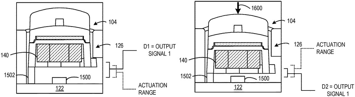
In another example shown inFIGS. 15-17, the electronic input sensor includes a Hall Effect sensor1500. The Hall Effect sensor1500may be mounted to the printed circuit board122below the mounting platform126. The Hall Effect sensor1500may be configured to vary an output signal based on a magnetic field produced by the magnet140of the mounting platform126(or a magnet in the selected button accessory104). In particular, the Hall Effect sensor1500may have an actuation range in which the magnetic field may affect the output signal of the Hall Effect sensor1500such that the Hall Effect sensor1500may vary an output signal responsive to the magnet140entering the actuation range.
As shown inFIG. 15, when no touch is applied to the selected button accessory104, the mounting platform126resides in the default posture. In the default posture, the magnet140is positioned above the actuation range of the Hall Effect sensor1500at a first distance (D1). As such, the Hall Effect sensor1500may produce a first output signal indicating no actuation of the push button (or may produce no output signal).
As shown inFIG. 16, the mounting platform126moves into the actuation range of the Hall Effect sensor1500responsive to a touch1600being applied to the selected button accessory104when the selected button accessory104is affixed to the mounting platform126. In particular, the magnet140is positioned at a second distance (D2) that causes the Hall Effect sensor to produce a second output signal different than the first output signal produced when the magnet140was positioned at the first distance. In particular, the second output signal may indicate actuation of the push button.
As shown inFIG. 17, the mounting platform126moves further into the actuation range of the Hall Effect sensor1500responsive to the touch1600being further applied to the selected button accessory104when the selected button accessory104is affixed to the mounting platform126. In particular, the magnet140is positioned at a third distance (D3) that causes the Hall Effect sensor to produce a third output signal different than the first and second output signals. In one example, the first output signal is 5 volts, the second output signal is 3 volts, and the third output signal is 1 volt. The Hall Effect sensor1500may output any suitable output signal based on a position of the magnet140.
In some implementations, the game controller100may be configured to interpret the output signal produced by the Hall Effect sensor1500in a binary fashion to determine whether or not the push button is actuated. For example, a threshold parameter (e.g., voltage) may be set to determine whether the push button is actuated. In one example, the threshold parameter may include a voltage corresponding to a distance associated with the far edge of the actuation range. The threshold parameter may be set to any suitable value.
In some implementations, the game controller100may be configured to vary an output signal relative to a distance that the mounting platform126(or the magnet140) moves into the actuation range of the Hall Effect sensor1500. In such implementations, the push button may be used to provide a variable or analog input that varies based on how far the push button is depressed.
In one example, in a baseball video game, a speed at which a pitcher throws a baseball may be varied based on how much the push button is depressed. For example, the push button may be depressed a lesser distance to throw a pitch slower, or the push button may be depressed a greater distance to throw a pitch faster.
In some implementations, a return mechanism1502may be positioned between the mounting platform126and the printed circuit board122. In particular such a return mechanism may be included in implementations that include Hall Effect sensor1500(or where electronic input sensor124does not comprise a collapsible switch). The return mechanism1502may be configured to allow the mounting platform126to translate toward the Hall Effect sensor1500responsive to the touch1600being applied to the selected button accessory104. Further, the return mechanism1502may be configured to return the mounting platform126and the selected button accessory104to a default posture responsive to the touch1600being lifted from the selected button accessory104. In one example, the return mechanism1502may include a spring. In another example, the return mechanism1502may include a collapsible or deformable member having similar characteristics to the collapsible switch1300ofFIGS. 13-14. The return mechanism1502may include any mechanism that returns the mounting platform126to the default posture. In implementations of the game controller100in which the mating platform126is omitted, the return mechanism1502may interface directly with the selected button accessory104to return the selected button accessory104to a default posture responsive to the touch1600being lifted from the selected button accessory104.
Returning toFIG. 3, in some implementations, the game controller100may include a button identification device156configured to identify a selected button accessory104when the selected button accessory104is affixed to the mounting platform126. The button identification device156may be configured to associate a control signal with the identified button accessory104. The button identification device156may be configured to identify any button accessory104that is affixed to any mounting platform126of the game controller100. Further, the game controller100may be configured to output the control signal associated with the selected button accessory104responsive to actuation of the electronic input sensor124corresponding to the selected button accessory104while the selected button accessory104is affixed to the mounting platform126. In some implementations, a control device other than the button identification device156may associate a control signal with an identified button accessory.
In one example, as shown inFIGS. 13-14, the button identification device includes a radio frequency identification (RFID) reader1308. Further, the selected button accessory104may include an RFID tag1311. The RFID reader1308may be configured to read the RFID tag1311to identify the selected button accessory104when the selected button accessory104is affixed to the mounting platform126. The RFID reader1308(or other control device) may be configured to associate an identifier corresponding to the RFID tag of the selected button accessory104with a control signal. Furthermore, the game controller100may be configured to output the control signal responsive to actuation of the collapsible switch1300while the selected button accessory104is affixed to the mounting platform126.
In another example, the button identification device156may be configured to identify a selected button accessory based on output signals produced by the Hall Effect sensor1500. In particular, different button accessories may include different magnets that produce different magnetic fields identifiable by the Hall Effect sensor. For example, a first button accessory may include a first magnet that produces a magnetic field having a first magnitude that causes the Hall Effect sensor1500to produce a first output signal. Further, a second button accessory may include a second magnet that produces a magnetic field having a second magnitude that causes the Hall Effect sensor1500to produce a second output signal. The first signal and the second signal may differ based on the difference in magnitudes of the different magnetic fields. Further, the different signals may act as baseline signals that may be associated with the different button accessories.
An identified button accessory may be associated with any suitable control signal or operation. In some implementations, each differently configured button accessory may be associated with a different control signal. In some implementations, two or more differently configured button accessories may be associated with the same control signal or operation. In some examples, each identified button accessory that is affixed to the game controller100may be associated with a different control signal or operation. In some examples, two different identified button accessories that are affixed to the game controller100may be associated with a same control signal (or operation).
By associating different control signals or operations with different button accessories, different button accessories may be swapped on the game controller100to customize the functionality of the game controller100. In one example shown inFIG. 18, a first set of button accessories1800(e.g.,1800A,1800B,1800C,1800D) may be affixed to the game controller100. The first set of button accessories1800may be configured to perform a first set of operations. For example, the first set of button accessories1800may be configured for playing a first-person-shooter (FPS) video game. In particular, a first button accessory1800A may be associated with a shoot operation, a second button accessory1800B may be associated with a reload weapon operation, a third button accessory1800C may be associated with a switch weapon operation, and a fourth button accessory1800D may be associated with an aim weapon operation. The first set of button accessories1800may be affixed to the game controller100any time a user plays a FPS video game. In some examples, the operations associated with the button accessories may be more specific to the particular video game. In other examples, the operations associated with the button accessories may be less specific to the particular video game. For example, the first set of button accessories may be a default set of button accessories.
In another example shown inFIG. 19, a second set of button accessories1900(e.g.,1900A,1900B,1900C,1900D) may be affixed to the same game controller100. The second set of button accessories may be configured to perform a second set of operations that differs from the first set of operations of the first set of button accessories1800. For example, the second set of button accessories1900may be configured for watching television. In particular, a first button accessory1900A may be associated with an increase sound volume operation, a second button accessory1900B may be associated with a decrease channel operation, a third button accessory1900C may be associated with a decrease sound volume operation, and a fourth button accessory1900D may be associated with an increase channel operation. The second set of button accessories1900may be affixed to the game controller100any time a user watches television. Moreover, the second set of button accessories1900and the first set of button accessories may be easily swapped on the game controller100when a user goes from watching television to playing a FPS video game.
In some examples, a same set of button accessories may be rearranged on the game controller100to customize which push buttons perform which operations. For example, the first button accessory1900A and the second button accessory1900B could be swapped to make the two volume controls adjacent and the two channel controls adjacent on the game controller100.
Although the above examples describe operations as being grouped into particular sets, any individual button accessory may be affixed to the game controller100to customize a particular operation.
Returning toFIGS. 2-3, in some implementations, the plurality of mounting platforms126may be configured such that a same selected button accessory104may be removably affixable to each of the plurality of mounting platforms126. For example, the different mounting platforms may include the same mating features. In some implementations, the plurality of mounting platforms126may be identical. Correspondingly, in some implementations, every button accessory104may include an underside134that is configured in the same manner such that any button accessory104may affix to any of the plurality of mounting platform126. For example, the different button accessories may include the same mating features.
In other implementations, two or more mounting platforms of the plurality of mounting platforms126may be differently configured such that a same selected button accessory104is not removably affixable to the two or more mounting platforms. For example, the different mounting platforms126may include differently configured mating features that are compatible with button accessories having cooperating mating features.
In other implementations, two or more mounting platforms of the plurality of mounting platforms126may be configured such that a first button accessory is removably affixable to a first mounting platform, and the first button accessory is not removably affixable to a second mounting platform. Further, a second button accessory that is differently configured than the first button accessory may be removably affixable to the first mounting platform and the second mounting platform.
In one example shown inFIG. 20, a plurality of mounting platforms2000(e.g.,2000A,2000B,2000C,2000D) of the game controller100each include a differently configured set of mating features. In particular, a first mounting platform2000A includes four mating features, a second mounting platform2000B includes two mating features, a third mounting platform2000C includes one mating feature, and a fourth mounting platform2000D includes three mating features. As such, each mounting platform2000may be configured to be compatible with a different set of button accessories such that the button accessories in the set may be configured to only be removably affixable to that mounting platform.
In another example, two of the mounting platforms may be configured in the same manner, which may differ from a configuration of another mounting platform. In such an example, a selected button accessory may be removably affixable to the two mounting platforms, but may not be removably affixable to the other mounting platform. In another example, each mounting platform may include a same number of mating features, but the mating features may be radially spaced apart differently on the different mounting platforms such that the mating features may be differently configured. Mating features of different mounting platforms may be differently configured in any suitable manner.
Continuing withFIG. 20, in some implementations, each of the plurality of mounting platforms2000may include a visual indicator2002(e.g.,2002A,2002B,2002C,2002D) that indicates a selected button accessory type that is removably affixable to the mounting platform. For example, the first mounting platform2000A includes a “Y” visual indicator2002A. Likewise, each button accessory that is compatible to affix to the first mounting platform2000A may include the same “Y” visual indicator. Because some button accessories may not be compatible with some mounting platforms, the visual indicators may be used to match button accessories with compatible mounting platforms. In some implementations, a visual indicator may provide instructions for aligning a button accessory with a mounting platform to affix the button accessory to the mounting platform. A mounting platform or a button accessory may include any suitable visual indicator.
In another example implementation, a game controller comprises an electronic input sensor, and a button-retention feature configured to removably affix a selected button accessory to the game controller through a magnetic attraction between the button-retention feature and the selected button accessory. The selected button accessory may be one of a plurality of differently configured button accessories removably affixable to the game controller. The selected button accessory may be configured to translate a touch applied to the selected button accessory to an actuation of the electronic input sensor when the selected button accessory is affixed to the game controller. In one example implementation that optionally may be combined with any of the features described herein, the button-retention feature includes one or more magnets, and wherein the selected button accessory is made at least partially of ferromagnetic material having a magnetic attraction to the one or more magnets. In one example implementation that optionally may be combined with any of the features described herein, the button-retention feature includes ferromagnetic material, and wherein the selected button accessory includes one or more magnets having a magnetic attraction to the ferromagnetic material. In one example implementation that optionally may be combined with any of the features described herein, the game controller further comprises a component defining a mating feature configured to interlock with a corresponding mating feature on the selected button accessory to prevent the selected button accessory from rotating while affixed to the game controller. In one example implementation that optionally may be combined with any of the features described herein, the game controller further comprises a mounting platform configured to removably receive the selected button accessory, wherein the button-retention feature is configured to removably affix the selected button accessory to the mounting platform through a magnetic attraction between the button-retention feature and the selected button accessory. In one example implementation that optionally may be combined with any of the features described herein, the button-retention feature is included in the mounting platform. In one example implementation that optionally may be combined with any of the features described herein, the mounting platform includes a mating feature configured to interlock with a corresponding mating feature on the selected button accessory to prevent the selected button accessory from rotating about the mounting platform. In one example implementation that optionally may be combined with any of the features described herein, the electronic input sensor includes a collapsible switch configured to actuate responsive to a touch force applied to the selected button accessory when the selected button accessory is affixed to the game controller. In one example implementation that optionally may be combined with any of the features described herein, the electronic input sensor includes a Hall Effect sensor, and wherein the Hall Effect sensor varies an output signal responsive to the touch applied to the selected button accessory when the selected button accessory is affixed to the mounting platform. In one example implementation that optionally may be combined with any of the features described herein, each of the plurality of differently configured button accessories produce a different magnetic field that is identifiable by the Hall Effect sensor. In one example implementation that optionally may be combined with any of the features described herein, the game controller further comprises a button identification device configured to identify the selected button accessory when the selected button accessory is affixed to the mounting platform and associate a control signal with the selected button accessory. The game controller may be configured to output the control signal responsive to actuation of the electronic input sensor while the selected button accessory is affixed to the mounting platform. Each of the plurality of differently configured button accessories may be associated with a different control signal.
In another example implementation, a controller comprises a plurality of electronic input sensors and a corresponding plurality of mounting platforms. Each mounting platform may include a button-retention feature configured to removably affix a selected button accessory to a corresponding mounting platform through a magnetic attraction between the button-retention feature and the button accessory. The selected button accessory may be one of a plurality of differently configured button accessories removably affixable to the mounting platform. The mounting platform may be configured to translate a touch applied to the selected button accessory to an actuation of a different electronic input sensor of the plurality of electronic input sensors when the selected button accessory is affixed to the mounting platform. In one example implementation that optionally may be combined with any of the features described herein, each of the plurality of mounting platforms includes a visual indicator that indicates a selected button accessory type that is removably affixable to the mounting platform. In one example implementation that optionally may be combined with any of the features described herein, the plurality of mounting platforms are identically configured such that a same selected button accessory is removably affixable to each of the plurality of mounting platforms. In one example implementation that optionally may be combined with any of the features described herein, two or more mounting platforms of the plurality of mounting platforms are differently configured such that a same selected button accessory is not removably affixable to the two or more mounting platforms. In one example implementation that optionally may be combined with any of the features described herein, each of the plurality of mounting platforms include a mating feature configured to interlock with a corresponding mating feature of a selected button accessory to prevent the selected button accessory from rotating about the mounting platform, and wherein the two or mounting platforms include differently configured mounting features.
In one example implementation that optionally may be combined with any of the features described herein, the controller further comprises a button identification device configured to, for each of the corresponding plurality of mounting platforms, identify the selected button accessory when the selected button accessory is affixed to the corresponding mounting platform and associate a control signal with the selected button accessory. The controller is configured to, for each selected button accessory affixed to a mounting platform, output the control signal associated with the selected button accessory responsive to actuation of the electronic input sensor corresponding to the selected button accessory while the selected button accessory is affixed to the mounting platform. Each of the plurality of differently configured button accessories is associated with a different control signal. In another example implementation, a game controller comprises a first electronic input sensor, a second electronic input sensor, a first mounting platform and a second mounting platform. The first mounting platform includes a first button-retention feature and a first mating feature. The first button-retention feature is configured to removably affix a first button accessory to the mounting platform through a magnetic attraction between the first button-retention feature and the first button accessory. The first mating feature is configured to interlock with a corresponding first mating feature of the first button accessory to prevent the first button accessory from rotating about the first mounting platform. The first mounting platform is configured to translate a touch applied to the first button accessory to an actuation of the first electronic input sensor when the first button accessory is affixed to the first mounting platform. The second mounting platform includes a second button-retention feature and a second mating feature. The second button-retention feature is configured to removably affix a second button accessory to the mounting platform through a magnetic attraction between the second button-retention feature and the second button accessory. The second mating feature is configured to interlock with a corresponding second mating feature of the second button accessory to prevent the second button accessory from rotating about the second mounting platform. The second mounting platform is configured to translate a touch applied to the second button accessory to an actuation of the second electronic input sensor when the second button accessory is affixed to the second mounting platform. The first mating feature of the first mounting platform is differently configured than the second mating feature of the second mounting platform such that the second button accessory is not removably affixable to the first mounting platform and the first button accessory is not removably affixable to the second mounting platform. In one example implementation that optionally may be combined with any of the features described herein, the first mounting platforms includes a first visual indicator that indicates a first button accessory type that is removably affixable to the first mounting platform and wherein the second mounting platform includes second visual indicator that indicates a second button accessory type different than the first button accessory type that is removably affixable to the second mounting platform. In one example implementation that optionally may be combined with any of the features described herein, the first mounting platform includes a first number of mating features, and wherein the second mounting platform includes a second number of mating features different than the first number of mating features.
It will be understood that the configurations and/or approaches described herein are exemplary in nature, and that these specific embodiments or examples are not to be considered in a limiting sense, because numerous variations are possible. The specific routines or methods described herein may represent one or more of any number of processing strategies. As such, various acts illustrated and/or described may be performed in the sequence illustrated and/or described, in other sequences, in parallel, or omitted. Likewise, the order of the above-described processes may be changed.
The subject matter of the present disclosure includes all novel and nonobvious combinations and subcombinations of the various processes, systems and configurations, and other features, functions, acts, and/or properties disclosed herein, as well as any and all equivalents thereof.
Claims
- A game controller comprising: an electronic input sensor;and a mounting platform including a magnet configured to removably affix a selected button accessory to the mounting platform through a magnetic attraction between the magnet and the selected button accessory, the selected button accessory being one of a plurality of differently configured button accessories removably affixable to the mounting platform, the mounting platform and the magnet move together with the selected button accessory relative to the electronic input sensor responsive to finger manipulation of the selected button accessory when the selected button accessory is magnetically affixed to the mounting platform, and wherein the electronic input sensor is configured to produce an output signal based on a position of the magnet.
- The game controller of claim 1 , wherein the electronic input sensor is a Hall Effect sensor.
- The game controller of claim 2 , wherein the game controller is configured to compare the output signal of the Hall Effect sensor to a threshold parameter to determine whether or not the selected button accessory is actuated.
- The game controller of claim 2 , wherein the Hall Effect sensor is configured to vary the output signal based on the position of the magnet relative to the Hall Effect sensor.
- The game controller of claim 4 , wherein the game controller is configured to vary a control signal associated with the selected button accessory based on the output signal of the Hall Effect sensor.
- The game controller of claim 2 , wherein two or more of the plurality of differently configured button accessories produce different magnetic fields that are identifiable by the Hall Effect sensor.
- The game controller of claim 6 , wherein the game controller is configured to associate different control signals or operations with different identified button accessories.
- The game controller of claim 1 , wherein the mounting platform includes a topside and an underside opposite the topside, wherein the magnet is secured within a cavity formed on the underside of the mounting platform, and wherein the selected button accessory is removable from the mounting platform based on the magnetic attraction between the magnet and the selected button accessory being overcome by a removal force.
- The game controller of claim 1 , further comprising: a return mechanism configured to return the mounting platform to a default posture responsive to a touch being removed from the selected button accessory.
- A game controller comprising: a Hall Effect sensor;and a mounting platform including a magnet configured to removably affix a selected button accessory to the mounting platform through a magnetic attraction between the magnet and the selected button accessory, the selected button accessory being one of a plurality of differently configured button accessories removably affixable to the mounting platform, the mounting platform and the magnet move together with the selected button accessory relative to the Hall Effect sensor responsive to finger manipulation of the selected button accessory when the selected button accessory is magnetically affixed to the mounting platform, and wherein the Hall Effect sensor is configured to produce an output signal based on a position of the magnet.
- The game controller of claim 10 , wherein the game controller is configured to compare the output signal of the Hall Effect sensor to a threshold parameter to determine whether or not the selected button accessory is actuated.
- The game controller of claim 10 , wherein the Hall Effect sensor is configured to vary the output signal based on the position of the magnet relative to the Hall Effect sensor.
- The game controller of claim 10 , wherein the game controller is configured to vary a control signal associated with the selected button accessory based on the output signal of the Hall Effect sensor.
- The game controller of claim 10 , wherein two or more of the plurality of differently configured button accessories produce different magnetic fields that are identifiable by the Hall Effect sensor.
- The game controller of claim 14 , wherein the game controller is configured to associate different control signals or operations with different identified button accessories.
- The game controller of claim 10 , wherein the mounting platform includes a topside and an underside opposite the topside, and wherein the magnet is secured within a cavity formed on the underside of the mounting platform.
- The game controller of claim 10 , further comprising: a return mechanism configured to return the mounting platform to a default posture responsive to a touch being removed from the selected button accessory.
- A controller comprising: a plurality of Hall Effect sensors;and a corresponding plurality of mounting platforms, each mounting platform including a magnet configured to removably affix a selected button accessory to the mounting platform through a magnetic attraction between the magnet and the selected button accessory, the selected button accessory being one of a plurality of differently configured button accessories removably affixable to the mounting platform, each mounting platform and the magnet thereof move together with the selected button accessory relative to a corresponding Hall Effect sensor of the plurality of Hall Effect sensors responsive to finger manipulation of the selected button accessory when the selected button accessory is magnetically affixed to the mounting platform, and wherein the corresponding Hall Effect sensor is configured to produce an output signal based on a position of the magnet.
- The game controller of claim 18 , wherein each of the plurality of mounting platforms is configured such that a same selected button accessory is removably affixable to each of the plurality of mounting platforms.
- The game controller of claim 18 , wherein each of the plurality of differently configured button accessories produce a different magnetic field that is identifiable by the Hall Effect sensor such that a first set of button accessories is configured to perform a first set of operations when the first set of button accessories is affixed to the plurality of mounting platforms and a second set of button accessories is configured to perform a second set of operation that differs from the first set of operations when the second set of button accessories is affixed to the plurality of mounting platforms.
Disclaimer: Data collected from the USPTO and may be malformed, incomplete, and/or otherwise inaccurate.