U.S. Pat. No. 10,987,577
HAND-HELD GAME CONTROLLER WITH COOLING FEATURES
Issue DateAugust 8, 2019
Illustrative Figure
Abstract
A hand-held game controller with cooling features includes a housing with at least one hand grip extending therefrom which forms a hand grip cavity. The housing or the at least one hand grip has a plurality of openings therethrough. A motor has a rotatable shaft that is carried in the housing and the at least one hand grip and extends into the hand grip cavity. A fan is connected to the rotatable shaft which, when rotated by the rotatable shaft, generates air flow into and out of the plurality of openings.
Description
DETAILED DESCRIPTION OF THE INVENTION Referring now to the drawings, it can be seen that a hand-held game controller utilizes motors provided within the controller to operate fans which generate an air flow into and out of a plurality of openings provided within the hand grips and/or main body of the controller. Moreover, in some embodiments the fans are implemented to draw air in through the ends of the hand grips and direct a flow of air to areas where a player likely grips the controller. This air flow serves two primary purposes. First, the air flow helps to cool the motors and electronics which generate a significant amount of heat during use of the controller. Secondly, the air flow cools the controller hand grips which prevents a buildup of moisture, or sweat, on the player's hands. Different fan configurations are disclosed so as to accomplish the aforementioned purposes. Referring now toFIGS. 1-3, it can be seen that a hand-held game controller with cooling features is designated generally by the numeral10. The controller10includes a housing12which may be made of a polymeric material and which is designed and shaped for ergonomic benefits. Although the housing12shown in the drawings is configured to be gripped by both hands of the person playing the video game or other type of game, skilled artisans will appreciate that the features described herein are adaptable for use with a game controller in which only a single hand is used such as a flight controller joystick, or an automobile gearshift. In any event, the housing12provides for a main body14wherein the body14has a body cavity16which houses or contains the controller's internal components. Extending downwardly and somewhat outwardly from the main body14may be a pair of hand grips18wherein the suffix R is used with the right hand grip and the ...
DETAILED DESCRIPTION OF THE INVENTION
Referring now to the drawings, it can be seen that a hand-held game controller utilizes motors provided within the controller to operate fans which generate an air flow into and out of a plurality of openings provided within the hand grips and/or main body of the controller. Moreover, in some embodiments the fans are implemented to draw air in through the ends of the hand grips and direct a flow of air to areas where a player likely grips the controller. This air flow serves two primary purposes. First, the air flow helps to cool the motors and electronics which generate a significant amount of heat during use of the controller. Secondly, the air flow cools the controller hand grips which prevents a buildup of moisture, or sweat, on the player's hands. Different fan configurations are disclosed so as to accomplish the aforementioned purposes.
Referring now toFIGS. 1-3, it can be seen that a hand-held game controller with cooling features is designated generally by the numeral10. The controller10includes a housing12which may be made of a polymeric material and which is designed and shaped for ergonomic benefits. Although the housing12shown in the drawings is configured to be gripped by both hands of the person playing the video game or other type of game, skilled artisans will appreciate that the features described herein are adaptable for use with a game controller in which only a single hand is used such as a flight controller joystick, or an automobile gearshift. In any event, the housing12provides for a main body14wherein the body14has a body cavity16which houses or contains the controller's internal components. Extending downwardly and somewhat outwardly from the main body14may be a pair of hand grips18wherein the suffix R is used with the right hand grip and the suffix L is used with the left hand grip. The suffixes R and L may also be used with other components described herein. Each of the hand grips18form an internal grip cavity20, wherein each grip cavity may be contiguous with the body cavity16.
A number of user inputs22may be provided on the main body14. These inputs include but are not limited to joysticks24L and24R, input buttons26provided on the right side of the body14, and a plurality of input buttons28provided on the left side of the main body14. A touchpad30may be provided in a centrally located position on the main body14. The main body14may also provide for a headphone jack34and an external input port36. Other function buttons38may be provided. In some controllers, the housing12may provide for one or more toggle levers40which are positioned at a top edge of the main body14or immediately underneath the top edge of the main body on a rear surface of the housing12. A speaker port44may also be provided on the main body14.
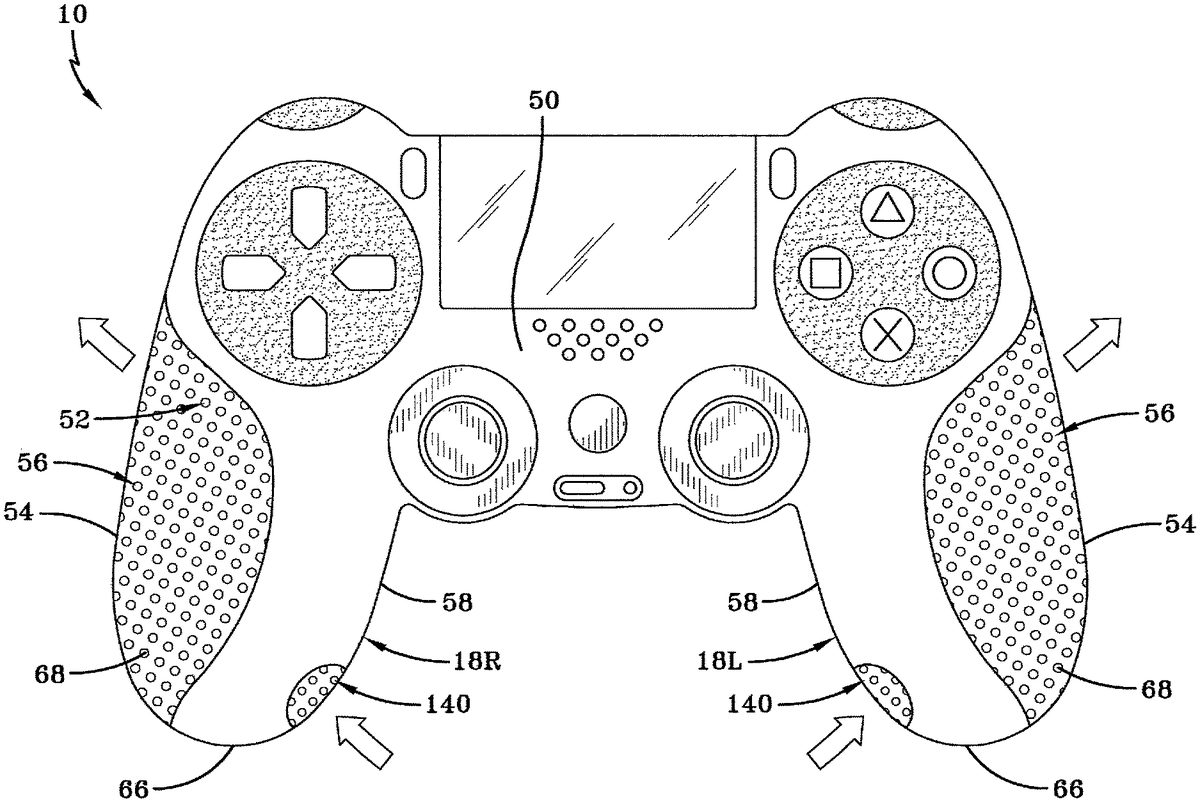
The main body14includes a front exterior surface50which faces the user and which may include the joysticks24, the input buttons26and28, and the other inputs22. The front surface50may be provided with front surface openings52which are contiguous with the body cavity16and may be of any appropriate size or shape. Indeed, all of the openings disclosed herein that extend through the housing12into either the body cavity or the grip cavities may be sized and/or shaped so as to facilitate air flow through the controller while minimizing the flow of moisture into the controller. The main body also has other exterior or external surfaces which may share or are immediately adjacent those of the front surface50. In particular, the hand grips16may provide for a lower palm exterior surface54wherein each lower palm exterior surface54provides a plurality of openings56which extend into the grip cavity20and/or the body cavity16. The surface54is where the player most often positions the portion of their palm immediately below their thumb during use of the controller. The hand grips18may also provide for an inner finger exterior surface58wherein the surface58provides for openings60extending therethrough and which are also contiguous with the grip cavity20and/or the body cavity16. The surface58is where the player often positions their fingers and finger tips during use of the controller.
As best seen inFIG. 2, the main body may include a back exterior surface62which covers the main body and the hand grips and which provides for back exterior surface openings64which are contiguous with the body cavity16and/or the grip cavities20. The surface62is primarily where the player will position their palm and fingers while using the controller.
The hand grips18also provide for end external surfaces66, which are at the distal end of the hand grips opposite the main body14. The surfaces66may provide a transition between the exterior surfaces50,54,58, and62. The end external surface66may provide for end external surface openings68therethrough which are contiguous with the grip cavity20. As will become apparent as the detailed description proceeds, air flow may fluidly proceed between from any one opening to any other opening depending upon configuration and/or operation of the fans as will be described.
As best seen inFIG. 3, the game controller10includes an internal controller80which sends and receives wired or wireless signals to and from a main controller (not shown) that runs the video game that is being viewed by the player. In other words, the internal controller receives and sends input signals via the inputs22to the main controller so as to interface with the video game. The internal controller80is powered by a power source or battery81wherein power from this power source or battery may be received from an external supply or may be contained in a rechargeable battery maintained within the housing12. Connected to the internal controller and powered by the battery81may be a single motor82in the case of a joystick-type hand-held game controller, or as shown in the present drawings the motors which may be provided internally within the grip cavities20. Each motor82includes a rotatable motor shaft84which may rotate in one direction or in some embodiments may rotate in either direction. In some embodiments, a shaker weight or weights88may be secured to the motor shaft84wherein rotation of the motor shaft rotates the shaker weights and generates a vibration within the housing12so as to provide for realistic experiences for the player. Skilled artisans will appreciate that in any of the embodiments described herein the shaker weights88may be eliminated so as to maximize the space utilized for the fans, as will be described.
In one embodiment, power is supplied to the motor82to rotate the shaft and the shaker weights, and also directly to a fan assembly, to be discussed below, that provides its own self-contained motor and which may operate independently of the motor82. Indeed, skilled artisans will appreciate that any of the fan assemblies disclosed herein may be self-contained in that they operate independently of the motors used to energize the shaker weights.
A fan assembly, designated generally by the numeral100, is received and maintained in the grip cavity20L, As best seen inFIG. 1, the fan assembly100includes a motor102that receives electricity in a controlled manner from the power81. The assembly100also includes an entry plate104which extends from internal surfaces of the hand grip18L within the grip cavity20L, wherein the entry plate104provides for an entry plate hole105. The entry plate104and the internal surfaces of the hand grip, and in particular the internal surfaces of the hand grip proximal an end of the hand grip, form an entry cavity106. The end of the hand grip provides the exterior surface openings68which are contiguous with the entry cavity106.
The fan assembly100includes a fan, designated generally by the numeral109. The fan109includes an entry disc110which is substantially planar in configuration and which has a disc eyelet112extending therethrough. The disc eyelet112is substantially aligned with the entry plate hole105. The fan109also includes a shaft disc114which is secured to an end or at least a portion of a motor shaft103rotated by the motor102. As such, in the present embodiment, the motor102and the fan109may be provided in a self-contained assembly substantially maintained within the hand grip cavity20L, In any event, connected in between the entry disc110and the shaft disc114are a plurality of vanes116which may be straight or curvilinear in configuration. Each vane provides for an internal edge120which is substantially aligned with an edge of the disc eyelet112and an external edge122which may be aligned with the outer peripheries of the entry disc110and the shaft disc114.
Positioned in a substantially parallel relationship with the entry plate104is an exit plate128. The exit plate may be connected to the internal surfaces of the hand grip within the hand grip cavity20. The exit plate128may also include an exit port132which is positioned between an interior surface sidewall of the hand grip and the exit plate. In particular, the exit port132is positioned, as best seen inFIG. 1, within the grip cavity20L and adjacent the lower palm exterior surface54of the hand grip18.
In an alternative embodiment, the fan assembly100may be configured without an internal motor, but instead operates from the motor82and its shaft84as shown in the hand grip18R. In such an embodiment, the exit plate128provides for a shaft hole130extending therethrough so as to rotatably receive and allow for rotation of the motor shaft. Skilled artisans will appreciate that a bearing or some other type of seal, which allows rotation of the shaft, may be interposed between the exit plate128, at the shaft hole130, and the rotating shaft84. All other structural features of the assembly shown in the hand grip18L may be utilized in the hand grip18R shown inFIG. 1.
In operation, rotation of the fan109, by either the motor102or the motor82, results in an airflow being generated between the openings68and the exit port132, and further with any of the other openings extending through the surface of the hand grip and/or surfaces of the housing. It is believed that the best cooling flow will be generated by rotation of the fan so as to draw air in through the openings68and axially into the disc eyelet112. Next, the air is radially expelled by the vanes116so as to exit the exit port132. This air flow, upon exiting the port132, then flows out any of the other openings maintained by the grip or housing so as to provide a cooling air flow. However, skilled artisans will appreciate that by reversing rotation of the motor shaft, that air flow may be reversible through the hand grips. In such a configuration, the position of the entry disc110and the shaft disc114would need to be switched, and in a similar manner the orientation or positioning of the exit port132and the entry plate hole105would need to be switched.
Referring now toFIGS. 4 and 5, it can be seen that an alternative fan configuration may be utilized in the controller10. In this embodiment, the end surface66may provide for an end surface opening140which is positioned at a distal end of the hand grip and, in the present embodiment, is shown on an inner surface of the hand grip facing the opposed hand grip. The end surface opening is aligned with a conduit142which has an entry end144aligned with the end surface opening140and, in some embodiments, may be integrally contiguous therewith. The conduit142also provides for an exit end146which extends into the hand grip cavity20. As shown inFIG. 5, the exit end146may be aligned with the disc eyelet112of the fan109. In this embodiment the fan109may be either operated internally by the motor102or externally by the motor82as shown inFIGS. 1-3. As a result, the rotation of the fan109by the appropriate shaft results in air flow being generated through the end surface opening140directly into the disc eyelet112. This axially directed air is then radially expelled by the vanes116whereupon the air is directed through the other openings provided by the main body14.
Referring now toFIG. 6, alternative embodiments of the fan may be incorporated into the grip cavities20. The hand grip18L incorporates a fan designated generally by the numeral109′. The fan109′ is directly associated with the shaft84and includes a plurality of vanes150. Each vane150provides for a shaft edge152which is directly connected to the shaft and a contour edge154which substantially conforms with but without touching the internal surface of the hand grip that forms the grip cavity20. The contour edge154and the internal surface of the hand grip18may form a gap160therebetween. Each vane also provides for an end edge156which extends from the shaft edge152to the contour edge154that is closest to the motor. Skilled artisans will appreciate that the vanes150may be planar or curvilinear in shape.
Rotation of the fan109′ will generate an air flow such that air may be directed throughout the main cavity and may draw air in from certain selected openings and expel the air through other selected openings. Internal louvers may be provided within the grip cavity or main cavity so as facilitate a desired air flow pattern through the interior of the main body14and the hand grips18.
The hand grip18R may incorporate a fan designated generally by the numeral109″. The hand grip18R may have an entry opening170at the end surface66. The fan109″ provides for a substantially frustoconical shaped entry disc172which substantially conforms with the internal surface of the hand grip. The entry disc172provides for a disc eyelet173which is substantially aligned with the entry opening170. Connected to the rotating shaft84is a shaft disc174which may be planar or of a slight conical configuration oriented in the same orientation as the conical shape of the entry disc172. Extending between each of the discs172and174are a plurality of vanes180. Each vane180provides for an internal edge182which is substantially straight and which extends from the entry disc eyelet173to the shaft disc174. Each vane180also provides for an external edge184which conforms and is in substantial contact with and may be connected to an interior surface of the entry disc172. Each vane may include an end edge186which is in contact with and may be connected to the shaft disc174. As seen inFIG. 6, the entry disc172extends to a position toward the shaft disc174but does not make contact therewith. As a result, the edge of the entry disc172, the edge of the shaft disc174, and the end edges186of the vanes180form a plurality of exit ports190.
As a result, rotation of the fan109″ draws air in through the entry opening170and axially into the disc eyelet173. The air is then directed downwardly along the surfaces of the vanes180and exits out the exit ports190into the grip cavity. From there, the air may exit any of the openings provided in the main body.
Based on the foregoing descriptions, the advantages of the present invention are readily apparent. The fans described may be independently operated or may be attachable to the motor shafts already provided in the commercially available game controllers, wherein those shafts are utilized to rotate shaker weights. In any of the embodiments described, the shaker weights may be removed or they may be associated with the fans as described herein. In any event, rotation of the fans within the hand grips generates an air flow which provides for cooling of the controller housing and also assists in keeping the player's hands cool and dry and helps to minimize the amount of sweat on their hands so that the controller can be firmly gripped and not result in the player's hands slipping on the controller, thereby ruining or disrupting their gaming experience.
Thus, it can be seen that the objects of the invention have been satisfied by the structure and its method for use presented above. While in accordance with the patent Statutes, only the best mode and preferred embodiment has been presented and described in detail, it is to be understood that the invention is not limited thereto or thereby. Accordingly, for an appreciation of the true scope and breadth of the invention, reference should be made to the following claims.
Claims
- A hand-held game controller with cooling features, comprising: a housing;at least one hand grip extending from said housing, said at least one hand grip forming a hand grip cavity, and at least one of said housing or said at least one hand grip having a plurality of openings therethrough;a motor having a rotatable shaft, said motor carried in one of said housing and said at least one hand grip, said rotatable shaft extending into said hand grip cavity;and a fan connected to said rotatable shaft, wherein rotation of said fan by said rotatable shaft generates air flow into and out of said plurality of openings, wherein said at least one hand grip has an end surface with at least one end surface opening extending therethrough and contiguous with said hand grip cavity, and wherein rotation of said fan draws air into said hand grip cavity through said at least one end surface opening and expels the air through said plurality of openings.
- The game controller according to claim 1 , further comprising: an entry plate carried in said hand grip cavity, said entry plate having an entry plate hole;an exit plate carried in said hand grip cavity, said exit plate having an exit port, said fan positioned in between said entry plate and said exit plate, wherein rotation of said fan draws air into said entry plate hole and expels air out said exit plate hole.
- The game controller according to claim 2 , wherein said exit plate hole is positioned in said hand grip cavity in proximity to a lower palm external surface of said hand grip.
- The game controller according to claim 1 , wherein said fan comprises: a plurality of vanes connected to said rotatable shaft, each said vane having a shaft edge connected to said rotatable shaft and a contour edge opposite said shaft edge, said at least one hand grip having a contour shape and said contour edge conforming substantially to said contour shape.
- The game controller according to claim 1 , wherein said motor and said fan are provided in a self-contained assembly maintained within said hand grip cavity.
- A hand-held game controller with cooling features, comprising: a housing;at least one hand grip extending from said housing, said at least one hand grip forming a hand grip cavity, and at least one of said housing or said at least one hand grip having a plurality of openings therethrough;a motor having a rotatable shaft, said motor carried in one of said housing and said at least one hand grip, said rotatable shaft extending into said hand grip cavity;a fan connected to said rotatable shaft, wherein rotation of said fan by said rotatable shaft generates air flow into and out of said plurality of openings, wherein said at least one hand grip has an end surface with at least one end surface opening therethrough, and wherein said fan has an entry disc with a disc eyelet therethrough;and a conduit extending between said at least one end surface opening and said disc eyelet, wherein rotation of said fan draws air through said conduit for delivery to said disc eyelet.
- The game controller according to claim 6 , wherein said at least one end surface opening is oriented near an inner finger external surface of said at least one hand grip.
- The game controller according to claim 6 , wherein said fan comprises: a plurality of vanes connected to said rotatable shaft, each said vane having a shaft edge connected to said rotatable shaft and a contour edge opposite said shaft edge, said at least one hand grip having a contour shape and said contour edge conforming substantially to said contour shape.
- The game controller according to claim 6 , wherein said motor and said fan are provided in a self-contained assembly maintained within said hand grip cavity.
- A hand-held game controller with cooling features, comprising: a housing;at least one hand grip extending from said housing, said at least one hand grip forming a hand grip cavity, and at least one of said housing or said at least one hand grip having a plurality of openings therethrough;a motor having a rotatable shaft, said motor carried in one of said housing and said at least one hand grip, said rotatable shaft extending into said hand grip cavity;and a fan connected to said rotatable shaft, wherein rotation of said fan by said rotatable shaft generates air flow into and out of said plurality of openings, wherein said at least one hand grip has an end surface with at least one end surface opening therethrough, and wherein said fan comprises: a shaft disc connected to said rotatable shaft;a plurality of vanes extending from said rotatable shaft, each said vane having an internal edge, an end edge connected to said shaft disc, and an external edge;and an entry disc having a disc eyelet in close proximity to said at least one end surface opening, each said external edge connected to said entry disc;said entry disc, said shaft disc, and said external edges forming exit ports, wherein rotation of said fan draws air in through said at least one end opening and into said disc eyelet and expels the air through said exit ports and out said plurality of openings.
- The game controller according to claim 10 , wherein said at least one hand grip has a contour shape and wherein said entry disc substantially conforms to said contour shape.
- The game controller according to claim 10 , wherein said motor and said fan are provided in a self-contained assembly maintained within said hand grip cavity.
- A hand-held game controller with cooling features, comprising: a housing;at least one hand grip extending from said housing, said at least one hand grip forming a hand grip cavity, and at least one of said housing or said at least one hand grip having a plurality of openings therethrough;a motor having a rotatable shaft, said motor carried in one of said housing and said at least one hand grip, said rotatable shaft extending into said hand grip cavity;a fan connected to said rotatable shaft, wherein rotation of said fan by said rotatable shaft generates air flow into and out of said plurality of openings;and a shaker weight secured to said rotatable shaft.
- The game controller according to claim 13 , wherein said fan comprises: a plurality of vanes connected to said rotatable shaft, each said vane having a shaft edge connected to said rotatable shaft and a contour edge opposite said shaft edge, said at least one hand grip having a contour shape and said contour edge conforming substantially to said contour shape.
- The game controller according to claim 13 , wherein said motor and said fan are provided in a self-contained assembly maintained within said hand grip cavity.
- The game controller according to claim 13 , further comprising: an entry plate carried in said hand grip cavity, said entry plate having an entry plate hole;an exit plate carried in said hand grip cavity, said exit plate having an exit port, said fan positioned in between said entry plate and said exit plate, wherein rotation of said fan draws air into said entry plate hole and expels air out said exit plate hole.
- The game controller according to claim 16 , wherein said exit plate hole is positioned in said hand grip cavity in proximity to a lower palm external surface of said hand grip.
Disclaimer: Data collected from the USPTO and may be malformed, incomplete, and/or otherwise inaccurate.