U.S. Pat. No. 10,974,135
INTERACTIVE GAME THEATER WITH SECRET MESSAGE IMAGING SYSTEM
AssigneeIndividual
Issue DateSeptember 27, 2018
Illustrative Figure
Abstract
A gaming platform including an interactive gaming system comprising multiple game access points physically distributed throughout a destination for conducting a physical-virtual game. Gamers carry electronically detectable identification means for identification at each game access point. Various mobile gaming devices are specified for accepting gamer input and for outputting game directives and content providing unique experiences including secret messages, all in accordance with the on-going game state. Participation earns sales benefits including the ability to purchase special themed toys or to receive discounts. A sales point is a variation of a game access point where the gamer makes a purchase effected by sales benefits and is identified and tracked within the sales point such that displays and actuatable devices in the store respond to the gamer. Gamers use or wear purchased products as gear to increase their in-game opportunities. The system summons gamers to destination game parts including themed characters.
Description
In the following description, numerous specific details are set forth, such as examples of specific components, types of usage scenarios, etc. in order to provide a thorough understanding of the present disclosure. It will be apparent, however, to one skilled in the art that the present disclosure may be practiced without these specific details and with alternative implementations, some of which are also described herein. In other instances, well known components or methods have not been described in detail in order to avoid unnecessarily obscuring the present disclosure. Thus, the specific details set forth are merely exemplary. The specific details may be varied from and still be contemplated to be within the spirit and scope of the present disclosure. DETAILED DESCRIPTION OF THE INVENTION ReferringFIG. 1, there is shown a block diagram depicting the overall structure of game theater system100, where remote gaming platform10services a multiplicity of physical destinations4-aand4-b, where non-ticketed destinations4-ainclude homes, shopping malls, resorts, casinos, gaming restaurants, and ticketed destinations4-binclude theme and amusement parts, museums, sporting and music venues and air-ports. Other anticipated physical destinations for use with the present and related co-pending applications that may or may not comprise restricted access (such as a ticketing or badge system) include colleges, universities and retirement communities. Regardless of the type of physical destination,4-aor4-b, each physical destination comprises one or more fixed or movable game access points such as30-a,30-band30-c, where all access points share common features especially including: 1) the ability to detect the proximity of one or more gamers2s(not depicted inFIG. 1) or one or more mobile gaming devices60(also not depicted inFIG. 1), and 2) the ability to exchange information with a gamer2susing input/output means such as herein described for receiving gamer2sgame actionable responses or providing to the gamer2sgame challenges, tasks, questions, clues, etc. or otherwise game content, 3) ...
In the following description, numerous specific details are set forth, such as examples of specific components, types of usage scenarios, etc. in order to provide a thorough understanding of the present disclosure. It will be apparent, however, to one skilled in the art that the present disclosure may be practiced without these specific details and with alternative implementations, some of which are also described herein. In other instances, well known components or methods have not been described in detail in order to avoid unnecessarily obscuring the present disclosure. Thus, the specific details set forth are merely exemplary. The specific details may be varied from and still be contemplated to be within the spirit and scope of the present disclosure.
DETAILED DESCRIPTION OF THE INVENTION
ReferringFIG. 1, there is shown a block diagram depicting the overall structure of game theater system100, where remote gaming platform10services a multiplicity of physical destinations4-aand4-b, where non-ticketed destinations4-ainclude homes, shopping malls, resorts, casinos, gaming restaurants, and ticketed destinations4-binclude theme and amusement parts, museums, sporting and music venues and air-ports. Other anticipated physical destinations for use with the present and related co-pending applications that may or may not comprise restricted access (such as a ticketing or badge system) include colleges, universities and retirement communities. Regardless of the type of physical destination,4-aor4-b, each physical destination comprises one or more fixed or movable game access points such as30-a,30-band30-c, where all access points share common features especially including: 1) the ability to detect the proximity of one or more gamers2s(not depicted inFIG. 1) or one or more mobile gaming devices60(also not depicted inFIG. 1), and 2) the ability to exchange information with a gamer2susing input/output means such as herein described for receiving gamer2sgame actionable responses or providing to the gamer2sgame challenges, tasks, questions, clues, etc. or otherwise game content, 3) the ability to exchange information such as gamer2sinput/output with the remote gaming platform10over any available communications network including the internet, and where access points30-afurther comprise a secret message output device22, access points30-bfurther comprise an actuated device50, and access points30-cfurther comprise both a secret message output device22and an actuated device50.
Access to ticketed physical destinations4-bsuch as theme parks is controllable using a self-access control5aapparatus and methods as taught in the related co-pending U.S. Non-Provisional application Ser. No. 16/055,078 entitled THEME PARK GAMIFICATION, GUEST TRACKING AND ACCESS CONTROL SYSTEM. To be further reviewed in upcomingFIG. 2, self-access control5aincludes the use of a smart ticket2, where the ticket2includes a remotely detectable ID for use in automatically tracking a guest of the destination as they move about within and throughout the destination4-b.
As taught in the co-pending application Ser. No. 16/055,078, self-access control5acan be used to control access to the entire physical destination4-b(referred to as a “venue” in the co-pending application) or what was referred to as a “sub-venue” that is any area within the venue including for example a fast lane for a theme park ride. The present application further teaches that this same self-access control5ais preferably used in any of its prior taught variations to also control access to any of the multiplicity of individual game access points such as30-a,30-bor30-c, in either a ticket destination4-bor a non-ticketed destination4-a.
As will be appreciated by those skilled in the art of destination management, the ability to limit access provides the option of charging for access, but then typically also requires the verification of proof-of-ticket and valid ticket ownership. For theme parks and museums, this verification typically requires staffing and/or sophisticated technology including a commonly shared fingerprint reader that requires guests to provide sensitive personal information and exposes them to public germs. The prior co-pending application in combination with the present invention teaches an important feature of a gaming theater, where the addition of the gaming theater to a physical destination continues to provide for ticketed/paid access while also not requiring additional staffing by the physical destination and not requiring the destinations guests to share personal information such as their fingerprint or facial image or to be exposed to public germs. Another advantage of these teachings is that individual game access points30can be further restricted even within a single physical destination4-aor4-b, thus providing for multiple paid levels of gaming activities.
Still referring toFIG. 1and as prior stated, another advantage of the self-access control5aapparatus and methods as prior taught in the co-pending application Ser. No. 16/055,078, is that destination guests can be tracked to specific locations, e.g. in a theme park a building, a public area, a ride and even a ride seat using any of a combination of technologies prior taught. This same prior taught smart ticket2(seeFIG. 2herein) apparatus and methods are useable for determining the proximity of a destination visitor such as a gamer2s(not depicted inFIG. 1) or a mobile gaming device60(seeFIG. 2herein) carried by the gamer2swith respect to a specific game access point such as30-a,30-bor30-c. As access points such as30-a,30-bor30-cdetect the incoming and outgoing presence of a particular gamer2sand/or any of their mobile devices60, this information is then automatically aggregated and transmitted from the destination4-aor4-bto the remote gaming platform10, where it is received and processed by at least the interactive gaming system48. The present application and prior co-pending applications anticipate that this detected gamer2spresence at a specific physical destination location including a game access point30, is also usable to automatically trigger the capturing of photos and other related information such as the time and location of the captured photo for either automatic or controlled distribution via the social platform10-4, where social platforms include for example Facebook, Twitter, Instagram, Snapchat, What's App, emails, texts and any other commonly shared social network. This feature is herein generally referred to as experience logging.
The present application further anticipates that upon detecting a gamer2s's presence at a game access point30, ad network10-3will process algorithms considering for example the gamer2s's persona, game state as well as the particular destination and game access point30identities to select and provide an advertisement to the gamer2s, using for example an available secret message output device22, an actuated device50(e.g. by outputting an audible message) or the herein taught magnifying glass15(seeFIG. 3) form of a secret message imaging glass that will be herein shown to include multiple user interface means for displaying information. Network10-3either provides an advertisement directly to a gamer2sthrough any of the available communication paths, and/or provides the advertisement to interactive gaming system48for incorporation with the game being played and presented to the gamer2s. Similar to network10-3, content repository10-2provides any of available multi-media content either directly to the gamer2striggered by a detection of the gamer2sat a game access point30, or to interactive gaming system48for incorporation with the game being played and presented with the gamer2s, where the multi-media content includes video, secret video and audio. The content repository10-2is also anticipated to receive images and video of gamers2scaptured by system cameras (not depicted) as the gamers2sinteract with a particular game access point30, where the received experience logging images and video is optionally provided to either the interactive gaming system48for incorporation as game content, the social platform10-3for distribution as social content, or the ad network10-3for combination and use with other ad content.
In the related co-pending U.S. Non-Provisional application Ser. No. 15/975,236 for an INTERACTIVE OBJECT TRACKING MIRROR-DISPLAY AND ENTERTAINMENT SYSTEM the present inventor anticipated that at least each of the ticketed physical destination4-bincluded a global eco-system40that further comprised a guest tracking system46as well as administration systems41(seeFIG. 2) including both a theme park administration system42and a hotel administration system44(see co-pending applicationFIG. 4.) The co-pending application also anticipated that the global eco-system40included the interactive gaming system48, which is herein shown to be alternatively included within remote gaming platform10as a preferred means for a single gaming platform10to service multiple physical destinations4-aand4-bwith possibly un-related ownership as a cloud services, as will be well understood by those familiar with software architecture including software as-a service (SAAS) models. As will be well understood by those familiar with ticketed destinations, it may be desirable to maintain some or all of interactive gaming system48, content repository10-2, ad network10-3, or social platform10-4within the exclusive control of the physical destination global eco-system48, as opposed to sharing the information on the remote gaming platform10. As such, the configuration presented inFIG. 1should be considered exemplary, as many variations are possible without departing from the scope of the present invention.
Still with respect toFIG. 1, gaming platform10provides game challenges, tasks, questions, clues, etc. or otherwise game content to a gamer2sand receives gamer2s's “actionable responses” that are for example answers or information interpretable as answers, or otherwise proof of the completion of a challenge, task or mission, etc. Several apparatus and methods are herein described and have been prior described in the related applications for exchanging game input/output between the gaming platform10and a gamer2s, where a special focus has been and is herein continued with respect to the output of secret message that are substantially only received by one or more controllably selected gamers2sand otherwise not perceivable to any other not selected gamers2sor on-lookers. While the present invention places a significant focus on only certain types of gamer input/output apparatus and methods, this should not be considered as a limitation of the present invention, as other apparatus and methods will be understood as useful for accepting input or providing output to a gamer2sthrough any of the fixed or movable game access points30. However, there is herein a general focus on either secret message output devices22, actuated devices50or mobile gaming devices60(seeFIG. 2.)
Gaming platform10also provides any of game content, ads and (actuated) device commands via its communications link with any of the game access points30within any of destinations4-aor4-b. As will be appreciated by those skilled in the arts of communication networks and local versus remote processing, it is possible that much of the higher bandwidth information such as game content from repository10-2be stored locally within a given game access point30, and where gaming platform10sends commands to the given game access point30to output any of this locally stored content, i.e. as opposed to for example streaming this content from the cloud to the given game access point30. As such, the configuration presented inFIG. 1should be considered exemplary, as many variations are possible without departing from the scope of the present invention.
Referring next toFIG. 2, there is shown a variation of the teachings of the prior co-pending U.S. Non-Provisional application Ser. No. 15/975,236 entitled INTERACTIVE OBJECT TRACKING MIRROR-DISPLAY AND ENTERTAINMENT SYSTEM, especially as these teachings relate to a global environment eco-system40and local environment eco-system30. The prior co-pending application taught what is herein generally referred to as a secret message output device22and what was prior specifically referred to as a mirror/display20(see e.g.FIGS. 1 and 2Aof the co-pending application.) This secret message output device22accepted input from, and provided output to a guest of a destination, where the examples of the co-pending application focused on a theme park. Anticipated physical locations for the device22included inside of the theme park or in a hotel room, either as a mirror/display or simply a display without a mirror apparatus. The device22optionally included means for detecting the presence and identity of a guest as well as tracking the gestures of an article12such as a wizard's wand being moved by the guest, where the gestures where interpretable as commands. The co-pending application further specified that the secret message output device22was capable of working with a local interactive gaming system36, other local environment sensors32for sensing any of a number of conditions in the local environment as well as an environment control system34for actuating or controlling any number of devices for creating local environment effects. The co-pending solutions anticipated that the guest would be connecting with other guests in a destination (theme park) wide game, where also the guest's local environment would become responsive to the state and changes in the game, e.g. automatically making thunder sounds while flashing lights.
Still referring toFIG. 2herein, the prior co-pending application roughly divided the information systems necessary for providing the prior taught functions into a local environment eco-system30and a global environment eco-system40. The local system30is herein renamed to a game access point30and continues to include the apparatus and methods generally taught in the co-pending application as environment sensing system32, environmental control system34and interactive gaming system36. The global environment system40still preferably includes guest tracking system46and administration system41, while the global interactive gaming system48is herein taught as separate from global eco-system40, instead becoming a part of remote gaming platform10. For destinations such as a theme park that includes multiple resorts, administration system41would preferably comprise a theme park administration system42separate from any one or more hotel administration systems44(see prior application for depiction of42and44.)
Still referring toFIG. 2herein, and specifically to the functions of guest tracking, the present inventor is also co-pending for an U.S. Non-Provisional application Ser. No. 16/055,078 entitled THEME PARK GAMIFICATION, GUEST TRACKING AND ACCESS CONTROL SYSTEM. In this co-pending application, guest tracking was shown to rely upon a smart ticket2that preferably included some form of an extended range readable ID, preferably in the form of a passive RFID. The prior application made note that such systems were well known in the art for tracking individuals, especially as they passed through physical “choke-points” leading into or out of a desired tracking location, for example a specific ride at a theme park. The prior application expanded upon the state-of-the-art to use additional technologies including pressure sensing plastics and fabrics, as well as cameras and image analysis, to combine with new methods for organizing and processing information in order to provide guest tracking down to the granularity of a single ride seat on a theme park ride. The smart ticket2was also taught to include a “venue app” (i.e. destination app) running on the guest's smart phone, where this app allowed the guest to provide sensitive personal information such as their fingerprint or image for proving their own identity without requiring touching a commonly shared fingerprint reader, ultimately allowing guests to self-control their own access to restricted areas without requiring the addition of destination staff.
The apparatus and methods for sensing the presence and proximity of a guest as they entered what is herein referred to as a game access point30(still including a ride at a theme park) were shown to fit within the earlier generalized teachings within the co-pending U.S. Non-Provisional application Ser. No. 15/975,236 for an INTERACTIVE OBJECT TRACKING MIRROR-DISPLAY AND ENTERTAINMENT SYSTEM with respect to local eco-system30's environment sensing system32. As such, the guest tracking apparatus and methods for locally sensing the guest remain a part of sensing system32and are so depicted in the presentFIG. 2, whereas guest tracking system46is representative of the global destination-wide software and database necessary for tracking the multiplicity of individual guest's movements across the multiplicity of game access points30. Hence, local apparatus for detecting guest presence remain within game access points30, whereas the resulting guest tracking information first determined by all access points30is then collectively associated and managed within guest tracking system46, and it is preferably guest tracking system46as a part of global eco-system40that communicates gamer (guest) tracking data to remote gaming platform10.
The present application continues to teach that the same apparatus for tracking the proximity of guests (and therefore the sub-set of guests who are also gamers) with respect to a game access point30are sufficient for detecting the presence of what is herein referred to mobile gaming devices60. In the prior co-pending U.S. Non-Provisional application Ser. No. 15/975,236 for and INTERACTIVE OBJECT TRACKING MIRROR-DISPLAY AND ENTERTAINMENT SYSTEM, the present inventor taught apparatus and methods for tracking secret message eye glasses14used by a gamer (guest2sin the co-pending application) to reveal secret messages, where the apparatus including Bluetooth, wi-fi local positioning systems as well as image processing of the emission of non-visible light by LEDs embedded within the glasses14. The present application generally refers to secret message eye glasses14and prior taught article12(e.g. a wizard's wand) as mobile gaming devices60, and will herein teach additional devices60. As with the tracking information detected by the apparatus and methods of the game access point30with respect to guests and gamers, the tracking information detected with respect to all mobile gaming devices60is communicated to global guest tracking system46for additional communication to interactive gaming system48. Especially when tracking game toys such as article12, the tracking apparatus and methods were generally taught as local interactive gaming system36, where gaming system36generally also comprises the secret message output devices22, as taught both prior and herein, all as depicted with respect to the presentFIG. 2.
What is most important to understand about the relationship between the prior co-pending applications and the present invention is that the original teachings for a mirror/display20in communications with a local environment eco-system30and global environment eco-system40where further detailed to specify a guest tracking and self-access5asystem using a smart ticket2, where the guest tracking information is aggregated into the global guest tracking system46thus providing valuable information for destination wide-gaming. Specific examples where also provided of actuated devices50including theme park ride examples of positioned, time special effects56aand positioned un-timed special effects56b, thus providing valuable physical means for effecting a gamer that worked in conjunction with the virtual means of outputting secret messages for viewing through prior taught eye glasses14. The present application further delineates and expands upon these teachings by moving the global interactive gaming system48away from the exclusive domain of the destination (i.e. global eco-system40) to a remote function capable of simultaneously serving multiple destinations providing a valuable extension to the gaming system. The present application also generalizes the mirror/display20into a secret message output device22and teaches a second projection-based apparatus and method for achieving a similar effect from the perspective of both the gamer and non-gamer. The prior eye glasses14are generalized as secret messaging image devices within a broader category of mobile devices60, a category that also includes game toys such as prior example wand12. A new alternative imaging glass is herein taught in the form of a magnifying glass15and a new interactive game toy is taught in the form of a sword62-swd(seeFIGS. 11 and 12) and a gun62-gun(seeFIG. 13).
Referring now toFIG. 1andFIG. 2, as will be well understood by those familiar with sophisticated hardware and software architectures such as described in the present and co-pending applications, many variations exist, and therefore the preferred and alternative apparatus and methods as taught should be considered as exemplary, rather than as limitations of the present invention. The scope of the present system includes any gaming system that provides secret messages to gamers2swhile simultaneously providing public images to non-gamers2o, a very important feature for converting a themed destination4-a,4-binto a gaming theater100without adversely affecting the experiences of the non-gamer2o. The scope also includes independent game access points30, with or without separate gamer self-serve access5a, where each access point is capable of minimally: 1) detecting and tracking the presence of the gamer2sand any of the gamer's mobile gaming devices60including secret imaging devices, game clothing and game toys, 2) communicating with an interactive gaming48system capable of managing games limited to a single physical destination4-a,4-bor extending across multiple physical destinations4-a,4-b, especially where the destinations4-a,4-bhave different ownership, themes, ticketing, control systems, etc., 3) controlling any combination of secret message output devices22and actuated devices50with respect to a gaming system that in part uses the detected and tracked gamer2sand mobile gaming device60information to controllably alter the gaming experience of an individual gamer2s, including the presentation of ads10-3and content10-2along with the exchange of game questions and answers, and 4) automatically capturing images and video of any of the multiplicity of gamers2sfor aggregation in a content repository10-2or distribution across any social media platform10-4, where the images and video are associable based upon the tracking information associated with individual gamers2s, and where the aggregated information further includes any of the other data representative of the gamer2s's individual experiences such as questions and answers, achievement levels, persona, etc.
The present invention will expand upon this scope to further include amongst other important features any destination gaming system that: 5) provides gamer identification information for embedding within or associating with one or more products sold by destination shops, where the products are then used by the gamer2sas mobile gaming devices60at one or more game access points30, where the products as devices60are then automatically detected and tracked by the access points30, and where the tracking information is used at least in part to effect the gaming experience of the gamer, 6) provides gamer information to a destination store, for example selling food or merchandize to the gamer2s, where the gamer information is used at least in part to determine any of sales benefits that effect the gamer2s's final sale, including products available to purchase, price or discounts, 7) provides gamer information to a destination store, for example selling food or merchandize to the gamer2s, where the store at least in part uses this information in combination with store information regarding the purchased products or services to output game information on the gamer's sales receipt, where the game information includes visible markings such as text, pictures or bar codes or non-visible markings such as made using non-visible ink, and where the gamer2suses a mobile game device60to either enter the game information or capture an image of the game information, and where the entered or captured image of the game information are used at least in part as a gamer's actionable response for effecting the gaming experience of the gamer, 8) provides an automatic vending system comprising any form or structure, where the vending system that is connected to the gaming system preferably as an actuated device50in conjunction with a game access point30, where the gamer2sinteracts with the vending system to cause a product to be dispensed to the gamer including a mobile gaming device60, where the dispended products as devices60are then automatically detected and tracked by the access points30, and where the tracking information is used at least in part to effect the gaming experience of the gamer, 9) provides a mobile gaming device60such as the herein taught magnifying glass15including apparatus and methods for directing a gamer on a search to find any one or more destination locations including a specific game access point30or any other pre-known destination location that is not a game access point30, 10) provides a mobile gaming device60such as the herein taught magnifying glass15including apparatus and methods for providing a visible “key” output on the imaging device that can be visually aligned to a visible “lock” embedded or attached to the destination4-a,4-b, where the gamer2saligns the key with the lock and captures an image of the combined symbol, and where the image of the combined symbol is used at least in part to effect the gaming experience of the gamer, 11) where a gamer2sinteracts with a game toy that is tracked at a game access point30, and where images are output at least in part in response to the detected presence or movements of the gamer or game toy, 12) where a gamer2sinteracts with a game toy that is detected at a game access point30, and where the game access point sends signals to the game toy that cause physical changes to the toy including vibration and outputting light, 13) where a gamer2suses an secret message image device22such as prior taught eye glasses14or herein taught magnifying glass15to capture images that are transmitted to the gaming system for processing in order to classify and identify objects within the captured images, and where the resulting classification or identification information are used at least in part as a gamer's actionable response to effect the gaming experience of the gamer, 14) where a gamer uses an secret message imaging device such as prior taught eye glasses14or herein taught magnifying glass15to first emit non-visible energy such as ultraviolet light to expose a secret message formed using invisible ink, where the gamer2sthen uses the imaging device to capture an image of the secret message, and where the secret message is used at least in part as a gamer's actionable response to effect the gaming experience of the gamer, 15) where a gamer2suses a secret message imaging device such as prior taught eye glasses14or herein taught magnifying glass15, or the gamer2suses their smart phone running a game app to capture images of either a themed character or another guest prior to that character or another guest first capturing their image, where the timing of the capturing of images by gamers2swith respect to themed characters or other guests is then used at least in part as a gamer's actionable response to effect the gaming experience of the gamer2s, or 16) where a gamer2suses a secret message imaging device such as prior taught eye glasses14or herein taught magnifying glass15, or the gamer uses their smart phone running a game app to capture images of any destination location, object or symbol, or secret messages, where any of the images or the timing or the sequence of their capture is then used at least in part as a gamer's actionable response to effect the gaming experience of the gamer.
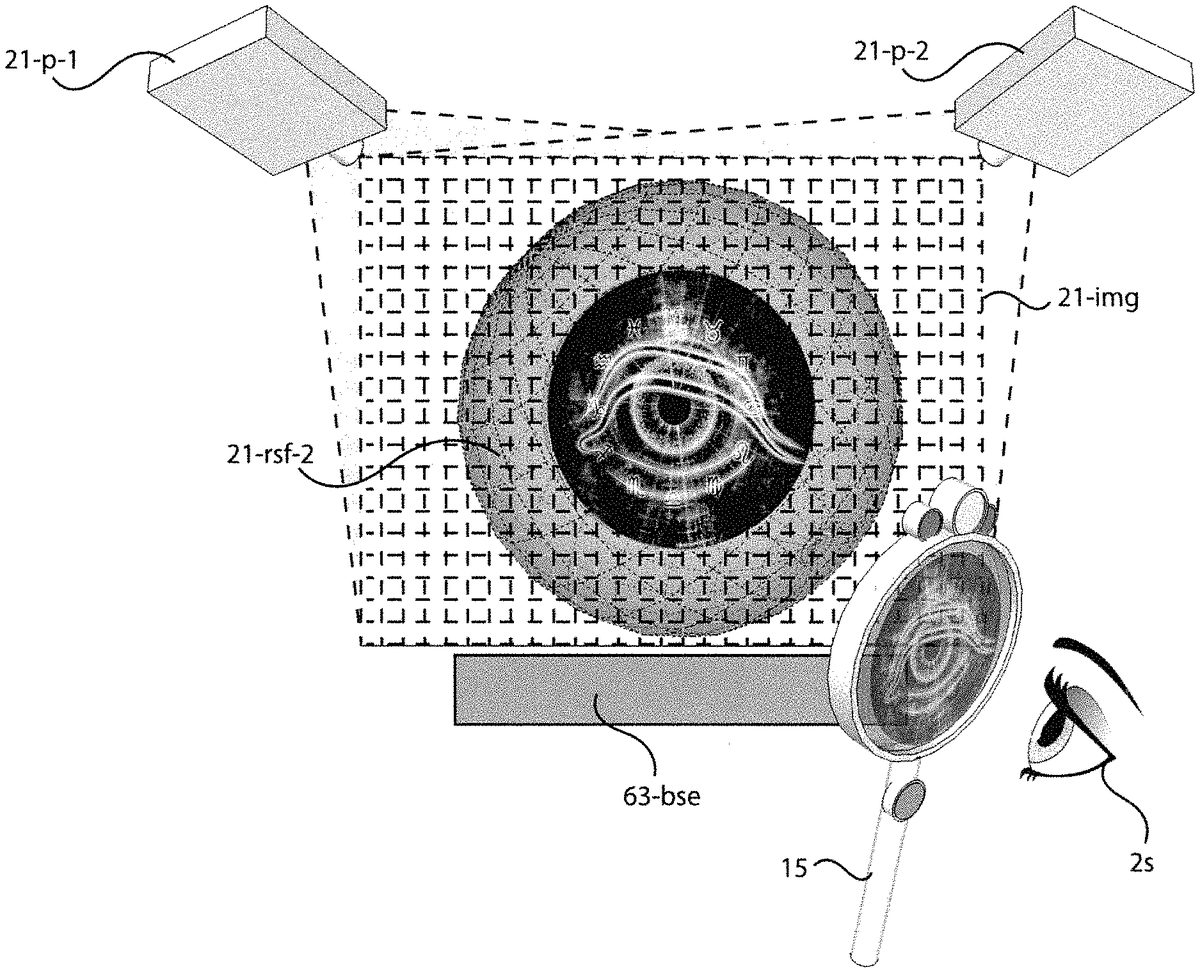
Referring next toFIG. 3, there is shown a perspective view of a secret message output device22for providing a public image21-imgoutput by an image projection source21-pfor receiving through an secret message imaging device such as magnifying glass15or eye glasses14, where the public image21-imgfurther comprises a secret image A polarized in a first orientation as well as an orthogonally polarized complimentary image B (as to be discussed in greater detail with respect to upcomingFIG. 4) and where substantially only the secret image A is viewable through the magnifying glass15(or eye glasses14) and only the public image is viewable with the naked eye. The present application is a continuation-in-part of U.S. Non-Provisional application Ser. No. 15/975,236 entitled INTERACTIVE OBJECT TRACKING MIRROR-DISPLAY AND ENTERTAINMENT SYSTEM. The base patent taught the output of public and secret images using various display technologies especially including an LCD display fitted with a second modulator, where the second modulator encoded the secret image within the output public image. The base patent also anticipated the use of projection systems for outputting a secret image within a public image21-imgas will be herein described in greater detail.
Referring now to bothFIG. 3andFIG. 4, image projection source21-pmay be a single projector21-pcapable of outputting the public image21-imgcomprising the secret A and complimentary B images, where the secret and complementary images have orthogonal polarizations, such as left/right circular or vertical/horizontal linear. The secret message imaging device such as magnifying glass15includes an appropriately selected polarizer for substantially blocking the complimentary image B while also transmitting the secret image A (as shown in detail inFIG. 4.) As will be well understood by those familiar with polarization systems, if the complimentary image B portion of public image21-imgis output by projector21-pwith a vertical polarization, and then is reflected off a reflective surface21-rsfcomprising a metallic versus non-metallic paint, the complimentary image B portion will substantially retain its vertical polarization. Likewise, if the secret image A portion of the public image21-imgis output by projector21-pwith a horizontal polarization, and then is reflected off a reflective surface21-rsfcomprising a metallic versus non-metallic paint, the secret image A portion will substantially retain its horizontal polarization. As will also be well understood by those familiar with polarization systems, if the magnifying glass15includes a polarization film placed such that its direction of polarization is essentially horizontal to the vertical axis of the magnifying glass15, then if the magnifying glass15is held in a substantially vertical/upright position with respect to the reflective surface21-rsf, the orientation of the polarizing film15-lpwill be parallel with the horizontally polarized reflection of the secret image A, such that the secret image A will be viewable through the magnifying glass15. As will be further understood, in this orientation between the magnifying glass15, reflective surface21-rsfand projector21-p, the complimentary image B portion of public image21-imgwill be substantially blocked.
Still referring toFIG. 3andFIG. 4, as the same magnifying glass15is rotated by 90 degrees, e.g. such that the magnifying glass15handle is held in a substantially horizontal/sideways position with respect to the reflective surface21-rsf, the orientation of the polarizing film15-lpwill become vertically aligned and therefore now perpendicular with the horizontally polarized reflection of the secret image A, such that the secret image A will be substantially blocked by the linear polarizer15-lpof the magnifying glass15, while the complimentary image B will be transmitted. The present inventor anticipates that this variability will be an attractive feature for the user of the magnifying glass15, as it adds to the suspense of the secret message. However, as will be discussed later in the present application with respect to upcomingFIGS. 5A, 5band5c, at least three means are provided for automatically adjusting magnifying glass15apparatus such that the secret images A contained within the public images21-imgare always substantially viewable through magnifying glasses15(or eye glasses14) while the complimentary images B are always substantially blocked.
Referring now toFIG. 3, also depicted are wireless communication means21-wcwithin projector21-pand wireless communication means15-wcwithin magnifying glasses15. As will be well understood by those familiar with 3D imaging systems and from a careful reading of the present invention's parent application U.S. Non-Provisional application Ser. No. 15/975,236 entitled INTERACTIVE OBJECT TRACKING MIRROR-DISPLAY AND ENTERTAINMENT SYSTEM, it is possible to emit secret images A within public images22that are timed through communication between means21-wcand15-wcwith the opening and closing of an LCD active shutter placed over linear polarizer15-lpon magnifying glass15. As described in detail in the base co-pending application, if several users of a secret message imaging device, such as eye glasses14(shown inFIG. 5of the parent application) or magnifying glass15shown in the present figure, are standing in front of a reflective surface21-rsfat the same time, then each use will see the same secret message A assuming that their secret message imaging device such as magnifying glass15is properly oriented to the polarization angle of the secret images A, all as will be well understood by those familiar with polarization systems and from a careful reading of the base and present applications. What is preferable, and as taught in the base co-pending application, by combining an active shutter with the linear polarizer15-lp, it is possible to send control signals to all imaging devices (e.g. magnifying glass15or eye glasses14) that are in view of the reflective surface21-rsf, such that the active shutter layer on all imaging devices that are not intended to see the secret image A is caused to be opaque at the same time that a secret image A is output by projector21-p, whereas the active shutter layer on all imaging glasses that are meant to see the secret image A is caused to be transparent at the same time that a secret image A is output by projector21-p. Hence, the ability of an secret message imaging device such as magnifying glass15taught in the present invention or eye glasses14taught in the base application to transmit a secret image A for viewing by a viewer/gamer2sis dependent upon the type (e.g. circular versus linear) and orientation (e.g. left/right or vertical/horizontal respectively) of the polarization layer of the imaging glass, and can be made further dependent upon the opacity of an active shutter layered onto the polarization layer, where without an active shutter layer all users of appropriate imaging devices will see the same secret image A and with an active shutter layer it is possible to restrict the secret images A to a select one or more imaging devices.
Still referring toFIG. 3, as will be understood by those familiar with 3D projection systems, LCD technology and from a reading of the parent application U.S. Non-Provisional application Ser. No. 15/975,236, there are several well-known apparatuses for implementing projector21-p. For example, one approach is to use two projectors21-p, where a first projector21-poutputs the secret image A while the second projector outputs the complimentary image B, spatially aligned on surface21-rsfso as to create public-secret image22. This technique is well understood for projecting left-eye/right-eye spatially aligned images in a 3D movie theater projection system. As will be well understood by those familiar with human vision, the naked eye viewing the reflective surface21-rsfwill combine the secret A and complimentary B images into what the viewer will perceive to be a single public image21-img. As will also be understood, if the secret image A is output simultaneously or near simultaneously with the complimentary image B, then light from the two images is perceived as additive, as such the intensity values of red, green and blue in the secret image A will add to the intensity values of red, green and blue in the complimentary image B. Using this understanding, it is possible to create a secret image A that for example contains some text, e.g. using pixels set to a red intensity of 128, a blue intensity of 128, and a green intensity of 0. The remaining non-text pixels in the secret image A are then displayed for example with a red intensity of 0, a blue intensity of 0, and a green intensity of 0. As seen through the magnifying glass15held at the proper orientation so as to only transmit the secret image A, the user2s(seeFIG. 4) of the magnifying glass15will see magenta (red-blue) text with a background color matching the ambient lighting colors reflected off of reflective surface21-rsf(since the light comprising complimentary image B is blocked by magnifying glass15.)
If simultaneously, or near-simultaneously a complimentary image B is then also output that for example contains pixels that are spatially aligned at the reflective surface21-rsfwith the text of secret image A, and these complimentary B text pixels are set to a red intensity of 128, a blue intensity of 128, and a green intensity of 256, then these complimentary B text pixels will cause the naked eye to see the secret image A text as being white (rather than magenta.) In this example, the RGB values of the secret message A text and complimentary image B text add up to be red=256, blue=256 and green=256, which is then perceived by the naked eye as white of intensity 256. The careful reader will note that in the present example, all non-text pixels in both the secret image A and complimentary image B are set to RGB values of 0, thus providing no additional light to the naked eye beyond the reflection of the ambient lighting off reflective surface21-rsf. Under circumstances of a well-lit room such as in a museum, this is expected to be ideal as this minimizes the overall output of light. However, the following possibilities are illustrative of the range of uses of the present invention. First, all of the non-text pixels in the complimentary image B could be set to RGB values of 256, and thus all pixels in the public image21-imgwould have RGB values of 256 yielding an even intensity of white 256 across the entire surface21-rsf. Second, all of the non-text pixels in the secret image A could be set to some RGB values giving the non-text portion of secret image A some particular color (ideally not magenta) including for example white at a lower intensity of 50, where then the non-text pixels of complimentary image B are appropriately set such that the addition of the individual R, B and G intensity values for each non-text A and B pixel arrives at some common value, again for example 50. With all non-text pixels set to a combined red=50, blue=50 and green=50, then the non-text portion of the public image21-imgwill be perceived as a white light of intensity 50, whereas the text portion of the public image21-imgwill be perceived as white light of intensity 256. Again, the careful reader will see that many variations are possible for accomplishing different goals for public image21-imgwhile still outputting the same secret message A.
This same principal of additive light and human perception applies to both temporal as well as spatial perception. In other words, rather than using two projectors21-pto simultaneously output the secret A and complimentary B images, thus spatially combining the images on reflective surface21-rsfat the same moment in time, it is possible to use a single projector that temporally alternates between the output of a secret image A and the complimentary image B, at a frame rate fast enough so that the naked eye combines any two subsequent images, all as will be well understood by those familiar with human perception and movie display systems. Manufacturers such as RealD sell a push-pull electro-optical liquid crystal modulator that is placed immediately in front of a single projector21-p(or computer screen) for alternately polarizing the light from each subsequent video frame. Known as the “ZScreen,” the alternating images are left-circularly polarized and then right-circularly polarized. As will also be well understood by those familiar with 3D projection systems, it is possible to use a similar approach but to alternate between vertical-linear polarization and horizontal-linear polarization. Either method is considered sufficient for the workings of the present invention, although the circular polarization approach offers the advantage that as the magnifying glass15is rotated, the secret image A will still be transmitted, and the complimentary image B will still be blocked, all as is well known in the art.
As the careful reader of the parent U.S. Non-Provisional application Ser. No. 15/975,236 will see, it is also possible to build an LCD display for outputting a public image in its final red, blue and green intensity values, and then to adapt this LCD display with an overlaid second modulator which then further encodes this public image with a secret image A. Since the LCD display outputs the public image in a specific linear polarization orientation, the second modulator will twist this light up to 90 degrees on a pixel-by-pixel basis, encoding it such that the linear polarizer15-lpin the magnifying glass15will act as an analyzer revealing the secret image A by essentially cutting off various amounts of the red, blue or green light in the public image. This can be thought of as a subtractive, rather than additive technique. By using projectors that work with linear polarization rather than circular polarization, the magnifying glass15of the present invention, as well as the eye glasses14taught in the base application, will work with both the secret image A output by a first projector21-padding to the complimentary image B subsequently output by the first projector21-p(or simultaneously output by a second projector20-p) as well as the encoded secret image A being subtracted from the public image output by an LCD display that has been further adapted to include a second modulator as taught in the parent patent. However, using linear polarizers for15-lpwithin magnifying glass15brings up the issue where a user must then properly align the magnifying glass15to the reflective surface21-rsfand projector21-p, all as prior discussed. Also, as prior discussed, this is anticipated to be an acceptable effect contributing to the mystery of the secret message. It is also noted that the preferred addition of an active shutter overlaid onto linear polarizer15-lpin magnifying glass15works to perform the prior stated goals (and as taught in the base application) regardless of the orientation of the magnifying glass15with respect to the reflective surface21-rsfand projector21-p.
Still referring toFIG. 3, it is also possible to use an LCD projector that has been further adapted to include a second modulator, following the same teachings as described in the parent U.S. Non-Provisional application Ser. No. 15/975,236. Using this approach, the projector21-pwill output a single public image21-imgthat includes additional encoding representing the secret image A, where the secret image A is then revealed as the linear polarizer15-lpof the magnifying glass15subtracts red, blue or green intensity from the public image21-img. As will be understood by those familiar with polarization, imaging systems, human perception, projectors and displays, as well as from a careful reading of the base and present applications, the various apparatus described herein as well as in the parent application should be considered as exemplifications for encoding secret messages rather than limitations, as other apparatus are possible for achieving the same or similar additive or subtractive public images without departing from the scope of the present invention.
Still referring toFIG. 3, magnifying glass15preferably comprises: a) camera15-camfor taking pictures representative of the same visual images a user would see as they looked through the lens15-lp, where camera15-camis a adapted to detect the secret messages similar to the adaptations described herein for lens15-lpand all of its variants (such as15-lp-asand15-lp-as-mdas to be described in upcomingFIG. 5c) b) button(s)15-btnfor accepting user input, for example indicating that a picture should be captured using camera15-cam, where button(s)15-btnis alternatively adapted to include a finger print detector exactly similar to technology used on smart phone's such as the IPhone, such that an individual user of the magnifying glass15is identifiable by a finger print and this identity information is usable at least in part as information for the gaming system48of the present invention100, and c) lighting15-led, where visible light LED's project light towards the user2s(seeFIG. 4) indicative of the state of the magnifying glass15or game situation for which the magnifying glass15is being uses as a mobile gaming device60, and where non-visible light such as ultra-violet light is projected away from the user2stowards an object being viewed through the lens15-lp, such that if the object includes an invisible ink responsive to the non-visible light for then fluorescing visible light then the user2swill be enabled to see the otherwise invisible ink while looking through the magnifying glass15.
Referring next toFIG. 4, there are shown secret message output device22with exemplary rays A and B being projected onto reflective surface21-rsfwhere after rays A and B are then reflected off surface21-rsftowards both the naked eye of a viewer2oand the magnifying glass15, through which a viewer2sis looking at the surface21-rsf. The lens15-lp-asof glass15preferably also includes an active shutter for timing with at least the projector21-pthat outputs the rays of secret image A, all as prior discussed in relation toFIG. 3and as will be further understood by a careful reading of the base co-pending application. Also, as discussed in relation toFIG. 3, the properly oriented linear polarizer15-lpblocks complimentary image rays B while transmitting secret image rays A. It is well known in the art of 3D projection systems that light reflected from a non-metallic (dielectric) surface varies strongly with the direction of polarization and the angle of incidence and that this is not the case for an electric conductor such as a metal and therefore the present inventor prefers that reflective surface21-rsfcomprises a metallic paint or similar so as to reflect rays A and B with minimal polarization attenuation. There are many well-known paints in the marketplace that are sufficient for the purposes of the present invention. The present inventor also notes that the screens used in movie theaters for watching 3D movies projected from dual projectors such as Runco's d-73D are also ideal for use as reflective surface21-rsf. There are many well-known manufactures of these 3D movie screens such as Mocomtech, Stewart Silver and Elite Screens.
Referring next toFIG. 5A, there is shown variation magnifying glass15-1, comprising magnifying glass15that is further adapted to include frictionless ball bearing15-bbfor containing linear polarizer and active shutter lens15-lp-as. What is most important to see is that lens15-lp-asis now free to rotate inside of the ball bearing15-bb, where the bearing15-bbis then attached to the magnifying glass handle15-hdl. Affixed to freely rotating lens15-lp-asis sufficient weight15-wgtfor causing lens15-lp-asto continuously self-align due to the force of gravity pulling on the weight15-wgt, where the goal of the self-alignment is to maintain the proper orientation of the linear polarizer within the lens15-lp-aswith respect to the anticipated angle of polarization of the reflected rays comprising secret message A off surface21-rsf(see especiallyFIG. 4.) Ball bearings are well-known in the art and many options are available with varying price and coefficients of friction. The technique of weighting the interior object, in this case the lens15-lp-as, is also well-known in the art. Again, what is most important is that as the magnifying lens15is held upright, for example so that a viewer2smay look through towards a surface21-rsfas shown inFIG. 4such that secret message A is revealed, and then as the lens15-1is rotated in the X-Y vertical plane (seeFIGS. 5B and 5c) the lens15-lp-asis continuously adjusted by the force of gravity to maintain its “upright” linear alignment, e.g. horizontal, that corresponds to the linear polarization angle of the incoming secret message rays A. The sensitivity of the continuous alignment will at least depend upon the amount of weight15-wgt, the coefficient of friction in the ball bearing15-bb, as well as the speed and angle of rotation caused by the viewer2s, all as will be well understood by those skilled in the art of mechanical engineering. The sensitivity of adjustment is anticipated to degrade as the magnifying glass15-1is rotated about the Y-Z plane, specifically, as the glass15-1is for example tilted forward from an ideal vertical alignment to lean towards the surface21-rsfbeing viewed.
Referring next toFIG. 5B, there is shown variation magnifying glass15-2, comprising magnifying glass15-1that has been further adapted to omit weight15-wgtand include orientation sensors15-ors, processor15-procand motor15-mtr. Orientation sensors15-orsare well known in the art with a common use within today's smart phones. Typical sensors include accelerometers (one for every axis X, Y and Z) a gyro and magnetometer, where the combined data set increases accuracy, the processing of which is sometimes referred to as “sensor fusion.” What is most important is the regardless of the specific sensor(s) chosen, processor15-procreceives sufficient information for determining in real-time at least the approximate rotation in the X-Y plane and ideally also the rotation in the Y-Z and X-Z planes. Using this real-time information, processor15-procis able to controllable adjust the rotation of lens15-lp-asby electronically communicating signals to motor15-mtr, where motor15-mtrcan be any of a number of possible motors available in the market and preferably includes an interface for accepting digital commands from processor15-procand converting these into motor movement signals, all as is well known in the art of motor control systems. What is most important to see is that lens15-2relies upon sensing the orientation of lens15-2and then calculating appropriate adjustments to the rotation of lens15-lp-asin order to maintain proper alignment between the liner polarization within lens15-lp-asand the linear polarization angle of the incoming secret message rays A such that the rays A are substantially transmitted through the lens15-2for receiving by a viewer2s.
Referring next toFIG. 5C, there is shown variation magnifying glass15-3, comprising magnifying glass15-2that has been further adapted to omit motor15-mtrand include additional LC Modulator layer15-md. With respect to the linear polarizer within lens15-lp-as-md, modulator15-mdis placed in between the surface21-rsfbeing viewed and the linear polarizer layer, and with respect to the viewer2s, the linear polarizer is in between the viewer2sand the modulator15-md. As is well-known in the art of LCD displays, the purpose of the modulator is to twist the rays of incoming light, effectively rotating the linear angle of polarization of the incoming rays by up to 90 degrees. This is often referred to as a light valve, where if incoming rays, for example vertically polarized, are left un-rotated (i.e. value shut off) prior to entering a second horizontal polarizer, they will be substantially blocked. If these same incoming vertically polarized rays are rotated by 90 degrees (i.e. value fully open) therefore becoming horizontally polarized, they will be substantially transmitted. As is well known, varying degrees of transmission are possible based upon the amount of rotating by the light value/modulator, such as modulator15-md. In the alternate embodiment of magnifying glass15-3, the modulator15-mdreceives electronic signals from processor15-procthat uniformly direct the modulator15-mdto twist all rays (A or B) being reflected by surface21-rsfand entering lens15-lp-as-mdaccording to an amount sufficient to offset the determined amount of X-Y plane rotation of the magnifying glass15-3. Hence, rather than mechanically rotating the entire lens15-lp-asas shown inFIG. 5Busing a motor, the lens15-lp-as-mdis allowed to rotate while the modulator15-mdinstead rotates the incoming light rays, thereby achieving the same goal which is to allow incoming secret message rays A to be analyzed as intended by the linear polarizer in lens15-lp-as-md, such that the secret message image A is substantially viewable by gamer2slooking through glass15-3while the complimentary image B is substantially not viewable, regardless of the orientation of magnifying glass15-3with respect to the secret message A angle of polarization.
Referring next toFIG. 6, there is shown variation magnifying glass15-4, comprising magnifying glass15-3that has been further adapted to include electronics15-elcfor controlling projector15-lcdsuch as an LCD that emits augmenting image C towards angled transflective surface15-tf, where image C is then partially or substantially fully reflected towards viewer2sas it transmits through second lens15-as. Those familiar with technology generally referred to as a handheld or “pocket” TV will understand the purposes, functions and arrangements of projector15-lcdwith respect to transflective surface15-tfand viewer2s, as this arrangement provides a means for allowing projector15-lcdto emit an image C for viewing by gamer2sas if the image C was coming through lens15-lp-as-md, while also minimizing the impact on the shape and size of the magnifying glass. As will be well understood by those familiar with this technology as well as augmented reality glasses and heads-up displays, many variations are possible without departing from the scope of the present invention, where any projection method including active matrix LCD is sufficient for the purposes of the present invention. What is most important to see is that an additional image C is provided for use in magnifying glass15-3, where the image C is generated by digital information either stored within magnifying glass15-3, or streamed to glass15-3over its internal wireless communications link15-com(see upcomingFIG. 7.)
Still referring toFIG. 6, transflective surface15-tfcan be a range of materials including at least: 1) plastic, 2) glass, or 3) transflective LCD. As those familiar with Snell's law and the principals of the refraction and reflection of light will understand, there is a critical angle of incidence, typically around 45°, at which the projected image C will be fully reflected off for example glass surface15-tftowards gamer2s. As is also well known, this angle can be altered to fit the form and structure of the magnifying glass15-4with the effect of reducing from full to partial reflection. In the case of partial reflection, it is further desirable that interior was15-walsurrounding surface15-tfbe coated or painted for increased light absorption (e.g. using a black color) thus reducing the unwanted effects of reflections within the interior cavity of magnifying glass15-4. Alternatively, surface15-tfcan be constructed using a transflective LCD, in which case electronics15-elccan emit control signals that cause transflective LCD surface15-tfto reflect substantially all of the image C acting similar to a mirrored surface. Using a glass surface15-tffurther allows for the simultaneous transmission of secret image A through surface15-tfdirectly into the view of gamer2s, thus allowing images A and C to simultaneously received by gamer2s, and towards this end image C can be considered as augmenting the secret message A. Using transflective LCD surface15-tf, electronics15-elccan alternate the transflective LCD between a reflective vs. transmissive at a high frame rate, e.g. 30 to 60 fps, coordinated with the output of image C using projector15-lcd. As will be well understood by those familiar with human visual perception, at a sufficient frame rate, gamer2swill perceive image C as being mixed with image A and indistinguishable from the approach of using a glass surface15-tfrather than a transflective surface15-tf.
Still referring toFIG. 6, rather than having projected image C augment secret image A, it is further anticipated that electronics15-elcor similar (see the teachings for15-uiin upcomingFIG. 7) will controllably set the active shutter in lens15-lp-as-mdto opaque while simultaneously emitting image(s) C through projector15-lcd. In this example use, gamer2sis automatically switched from viewing either only secret image A, or combined image A and C, to viewing only image C. As the careful reader will see, using the disclosed arrangement of parts or their equivalents, many interesting effects are possible, some of which have been described, others of which will be obvious to those skilled in the necessary arts, and therefore these teachings related to the projection of image C for augmenting secret image A should be considered as exemplary, rather than limitations of the present invention. And finally, the present invention anticipates that images captured by back facing camera15-cam-bthat are meant to capture the secret image A as currently being viewed by gamer2sare then also transmitted via magnifying glass15wireless communications (see15-comin upcomingFIG. 7) to be received by the interactive gaming system48.
As will be well understood from a careful reading of the present invention, game access point30alone or in combination with gaming system48is responsible for determining and transmitting control signals to magnifying glass15for causing electronics15-elcto direct projector15-lcdto emit image C for visually combining with image A, where the timing of the emission of image C is coordinated to augment the view of gamer2sthrough magnifying glass15-4, and where images captured from back facing camera15-cam-bare analyzed by any one of, or any combination of electronics15-elccontained with magnifying glass15-4, access point30or gaming system48, in order to determine the current view of gamer2s. Access point30and or gaming system48is further capable of receiving images captured by back facing camera15-cam-band then applying a digital image C to the captured image representative of the gamer2's view, thus forming an augmented captured image substantially similar to what gamer2swould have viewed at the time the image was captured by camera15-cam-b.
Referring next toFIG. 7, there is shown a functional block diagram of four of the major components of the presently taught game theater100including: 1) game access point30, 2) secret message output device22, 3) secret message magnifying glass15, and 4) interactive gaming system48. Each of four major components includes a set of key sub-components to be described forthwith. It is important to understand that the present figure describes overall behavior and functionality that is preferably encapsulated in software/hardware sub-components roughly equivalent to those herein taught. However, as those familiar with software and hardware system architectures will understand, multiple alternative configurations are possible where the actual internal sub-components of each of the for major components30,22,15and48are implemented differently than herein shown while substantially providing the same functional behaviors for the interaction between the major components. As will also be understood, all the components generally require computing and communication apparatus. Unless specifically mentioned, additional necessary hardware apparatus is well-known and understood in the marketplace, for which multiple options are available, and therefor for clarity are not further taught herein.
In general, a game access point30using gamer/device detection30-detis capable of at least detecting the presence or one or more gamers2salong with zero or more mobile gaming devices60being carried by the gamer2s, where the gamer2s's detected presence includes some unique identifier (i.e. gamer ID) that may or may not be related to that gamer2s's personal identity (for example the ID could be registered to a fictitious gamer avatar, rather than the actual gamer2s's real name.) A game access point30also is in communications via30-comwith the interactive gaming system48, either directly or working through the guest tracking system46(seeFIG. 2) under the supervision of the destination4-aor4-b, such as included in the destination's global eco-system40. Therefore, the main responsibility of the game access points30is to detect gamers2sand their associated devices60for continuous updating of the gaming system48, where the game algorithms being implemented on the gaming system48alter the game activities based at least in part upon the detected gamer2sand device60information with respect to an access point30. It is further preferred that at least some of the game access points30include means for very accurately tracking the movements and gestures of either the gamer2sor a mobile device60being used by a gamer2s. In the prior co-pending application, the present inventor provided significant specification related to the camera-based object tracking system embedded within mirror/display20(see especiallyFIG. 2Aof co-pending U.S. Non-Provisional application Ser. No. 15/975,236 INTERACTIVE OBJECT TRACKING MIRROR-DISPLAY AND ENTERTAINMENT SYSTEM) where this mirror/display20was functioning as a game access point30as it detected the presence of the gamer2s, tracked the movements of the gamer's2sgame toy, i.e. the wizard's wand shown as article12, and then communicated this information to both a local interactive gaming system36and the global interactive gaming system48. The tracked movements of article12where considered to be interpretable as commands being issued by gamer2s. As will be well understood by a careful reading of the present and co-pending applications, while a game access point30might comprise additional sub-components, including a secret message output device22or an actuated device50, it minimally comprises gamer/device detection30-detand system communications30-com, and alternately also comprises object tracking30-ot.
Still referring toFIG. 7, in general secret message output device22comprises a sub-component for outputting a public image viewable to the naked eye, wherein a secret message A is hidden and can only be perceived by a gamer2susing a secret message imaging device such as eye glasses14or magnifying glass15. The co-pending application for an INTERACTIVE OBJECT TRACKING MIRROR-DISPLAY AND ENTERTAINMENT SYSTEM taught mirror/display20with several alternatives for outputting such public images with secret messages A. The present invention further teaches projection system22comprising projector(s)21-pfor projecting secret message image A and complimentary image B off of a reflective surface21-rsf, where a gamer2susing the same eye glasses14or magnifying glass15as used to see secret messages A output by mirror/display20would then also perceive secret messages A being output by projection system21-p. Regardless of the underlying image output technology, e.g. display20or projector21-p, secret message output device22preferably includes sufficient computing system for implementing both image A processing22-imgA and image B processing22-imgB. What is important to understand is that preferably a secret message output device22is in communications with the interactive gaming system48via a game access point30, such that the game access point30first detects the gamer2sin the proximity of the output device22, and then communicates with gaming system48in order to receive secret message instructions or content.
As will be well understood by those familiar with data transfer over communications systems, especially remote systems such as gaming platform10when communicating to physical destinations4-aand4-b, there are issues related to data latency that can be noticeable for example to the gamer2swhen viewing the output secret message A. One way to minimize latency is to minimize data transfer, this includes either pre-storing secret messages A, complimentary images B, or desired final public images on the secret message output device22. However, if the secret messages A are not pre-known and must be calculated, it is desirable that the gaming system48transfer a minimum of data to output device22for processing into a viewable secret message A by processing sub-component22-imgA. Ultimately, after secret message A is determined, created or otherwise generated it is also necessary to generate either a complimentary image B (i.e. for projection device21-p) or a public image that encodes the secret message (i.e. for mirror/display20) where this second generation is the responsibility of processing sub-component22-imgB. Again, while it is possible to generate both images A, B and the public image on the interactive gaming system48for communicating through the game access point30to the output device22, it is preferred that a majority if not all of this generation is done local to device22, wherein it is further possible that sub-components22-imgA and22-imgB be a part of game access point30rather than device22. While many configurations are possible, once images A, B and the public image are determined, created or otherwise generated, they are output by device22for viewing.
Still referring toFIG. 7, in general secret message viewing device15comprises a multiplicity of sub-components, most importantly including a lens for analyzing the public image to reveal the secret message A, all as prior taught herein as well as the co-pending U.S. Non-Provisional application Ser. No. 15/975,236 entitled INTERACTIVE OBJECT TRACKING MIRROR-DISPLAY AND ENTERTAINMENT SYSTEM. The analyzer is typically a polarizer film providing either linear or circular polarization, and a such is not an electronic device that needs controlling. All of the sub-components depicted inFIG. 7for device15are related to functions that are electronically variable. Especially as taught in the co-pending application in relation to eye glasses14, it is useful to at least include an LCD active shutter over the polarizer film for constructing magnifying glass15. LCD active shutters are well known, and as directed by active shutter control15-ascprovide at least two beneficial functions: 1) to make the entire surface of lens15-lp-asor15-lp-as-md(seeFIGS. 5A, 5B and 5C) either opaque or transmissive in synchronization with the output of secret messages A by output device22, thus allowing some secret message A viewing devices15and14to transmit secret messages to gamer2s, while other devices15and14simultaneously block these same messages A, and 2) to increase the opacity of some select portion (i.e. some pixels of the LCD active shutter) of the surface of lens15-lp-asor15-lp-as-md, thereby blocking the backlighting coming through the lens15-lp-asor15-lp-as-mdto the gamer2sresulting in for example an image or some text (see upcomingFIGS. 8C, 9A, 9C, 9E, 9E and 14) where this can be considered the output portion of a typical screen based user interface (UI.)
Still referring toFIG. 7, as will be well understood by those familiar with touch screen technology, it is possible to further adapt either lens system15-lp-asor15-lp-as-mdto include a touch sensor, whereby the resulting lens not only provides UI output but also serves to receive input from the gamer2sin the form of touch detection signals. As such, it is preferably that device15include user interface sub-component15-uithat is dedicated to managing both the input and output of the UI as enabled by lens system15-lp-asor15-lp-as-mdpreferably further adapted to include touch sensing means. As depicted inFIG. 3, device15further includes additional mechanical based user input means such as button(s)15-btn. As will be appreciated by those skilled in the art of toys and user input, many solutions are possible for accepting input from a gamer2sother than a touch screen lens or a button, any of which are possible for use with device15. As such, the UI elements depicted in the present invention related to magnifying glass15and in the co-pending invention related to eye glasses14should be considered as exemplary rather than as limitations. It is possible that some of the teachings as related to eye glasses14, such as heptic feedback, also be incorporated into magnifying glass15. Likewise, the buttons envisioned for device15could be adapted to device14. What is most important is that the gamer2shas ability to exchange information with the gaming system48using some UI elements on either device14,15or any of their anticipated alternates.
The present invention additionally prefers that magnifying glass15include at least a back facing camera15-cam-b(seeFIG. 6) for capturing images of the view through glass15substantially as seen by gamer2s. As will be well understood by those familiar with camera technology, it is possible to place the same lens materials as15-lp-asor15-lp-as-mdover back facing camera15, such that camera15capture images that include secret messages A. Several uses for the capturing of these images will be detailed in the remainder of the present application. It is also preferable that magnifying glass15include a front facing camera15-cam-ffor capturing images of the gamer2s. When including back facing camera15-cam-bor front facing camera15-cam-f, magnifying glass15preferably also includes camera management sub-component15-cmfor which many options are well-known in the art and possible. What is minimally necessary is that some computing element is available for directing the image capture timing and data transfer of either of camera15-cam-band15-cam-f. What is further desirable is that sub-component15-cminclude some memory and sufficient processing for preforming image processing, for example classifying or identifying objects within the images being captured by cameras15-cam-band15-cam-f. As will be well-known in the art, local processing on the device15or14is advantageous but then also adds to the cost and power requirement of device15or14, and as such either some or all of this desirable image analysis processing can be moved instead to either game access point30and/or interactive gaming system48. What is most desirable is that secret message imaging devices15and14at least include camera sufficient for capturing images of what the gamer2sis seeing with respect to both their natural ambient view as well as any secret messages A seen while viewing a secret message output device22. What is further desirable and to be further discussed herein, is that these same images are then usable at least in part as information by gaming system48for altering the ongoing game as experienced by gamer2s.
Still referring toFIG. 7, magnifying glass15is preferably further adapted to include led's15-led. Similar to cameras15-cam-band15-cam-f, these can be either front facing or back facing. When front facing, the LED's15-ledare meant primarily as indicators for the gamer2s, and as such are considered to be a part of the user interface of magnifying glass15, where a similar set of UI LEDs where taught in the co-pending application Ser. No. 15/975,236 in relation to eye glasses14. For instance, these LEDs could be caused to blink or stay steady based upon electronic signals output by user interface15-UI in response to instructions received by interactive gaming system48and/or game access point30. However, within the present application the back facing LEDs15-ledare anticipated to output a non-visible light such as UV in order to cause invisible ink to fluoresce thus revealing an invisible message to the gamer2sas they look through magnifying glass15(see especially upcomingFIGS. 8band10E.) These back facing led's preferably receive electronic signals from the illumination control15-icsub-component that works in coordination with camera management15-cm. As will be well understood by those familiar with camera systems and electronics, camera management15-cmcould also be adapted to output electronic signals for causing the back facing LEDs15-ledto turn on and off. Regardless of the implementation, as these and other variations are well-known and possible, it is important to see that at times the back facing LEDs15-ledwill illuminate invisible ink for the gamer2sto view, even though images may or may not also be captured by back facing camera15-cam-b.
Still referring toFIG. 7, magnifying glass15preferably includes any of available wireless technologies including Bluetooth or wi-fi, for example which the co-pending application specified regarding eye glasses14. It is also important to note that the choice of wireless technology also effects at least game access points30which communicate with mobile gaming devices60such as magnifying glass15and eye glasses14. As such, the choice for communications15-compreferably supports detection of secret messaging devices15and14by gamer/device detection30-detsub-component of access points30, all as prior discussed. Also, as prior taught in the co-pending application Ser. No. 15/975,236 in relation to eye glasses14, it is preferred that communications15-cominclude some information during communication uniquely identifying the magnifying glass15from all other mobile gaming devices60, where the many uses of such unique ID information are well known to those familiar with information systems and has been prior discussed in the co-pending application. And finally, to support the electronics, magnifying glass15is further adapted to include power management15-pmfor both providing power to all electronic elements within glass15and for preferably supporting recharging of power, for example using any of the wireless power transfer technologies now becoming available with portable devices such as smart phones. What is most important is the device15includes a power source, such as a battery that may be exchanged or recharged, and that this power is managed as it is supplied to all electronic components within device15, all as will be well understood by those skilled in the art of electronics and especially portable electronics.
Still referring toFIG. 7, in general interactive gaming system48comprises a multiplicity of sub-components for receiving gamer2sinput, processing game rules at least in part using the gamer input, and providing output to gamers2sat least using any of secret message output devices22, actuated devices50or mobile gaming devices60, and where preferably the gamer input and gaming system output are communicated from system48through communications sub-component48-comto game access points30for further transmission to devices22,50and60. As will be well understood by those familiar with computer system communications, many options and technologies are available for use in communications sub-component48-comand as such are not the focus of the present invention. What is most important to understand is that the communications architecture support data security over a wide area network that communicates between a local area network running at the destination for communications between the multiplicity of game access points30and the remote gaming platform10that is preferably implemented as a cloud-based system. It is also possible to implement an architecture where each game access point30is treated as an IoT (internet of things) networked device comprising sufficient embedded electronics, software and network connectivity to enable the access point30to exchange data with interactive gaming system48running either locally, e.g. within the physical destination's global eco-system40, or remotely, e.g. on a cloud computing service within the gaming platform10. What is most important is that gaming system48be able to electronically exchange information with game access points30, secret message devices22, actuated devices50and mobile gaming devices60.
Still referring toFIG. 7, gaming system48preferably includes an image/clue processing48-icpsub-component for initially processing inputs received from gamer2s, where these inputs vary from selections made through some UI interface or images captured especially of the scene and/or secret message currently being viewed by the gamer2sthrough magnifying glass15or eye glasses14. Clue processing48-icpis preferably capable of receiving and appropriately processing all inputs, thus being able to recognize identification information associated with the received input, where the identification information preferable includes unique ids for the gamer2s, the game access point30as well as at least the mobile gaming device60the provided the input. Clue processing48-icppreferably determines the type of input and when this input is an image provides this image to object classification and identification sub-component48-ocifor additional processing using any of well-known and emerging image processing techniques, especially including the use of deep neural nets that have proven to be significantly efficient and accurate for at least classifying objects found within an image. The present inventor notes that by identifying the ID of the game access point30through which the original input image was received, it is possible to reasonably limit the total number of potential objects of which the gamer2smight have captured an image, where this information regarding the limited number of potential objects is then used at least in part by object classification and identification sub-component48-ociwhen processing the image. What is most important is that gamer2sis able to capture images with or without secret messages, where these images include one or more objects, and where the objects are generally classifiable (e.g. the object is a fish) or they are uniquely identifiable (e.g. the object is a QR code on a printed receipt, or the face of another gamer2s.) When capturing images that include secret messages, it is anticipated that the exact secret message is pre-known by the gaming system48since system48was ultimately responsible for directing the output of the secret message to the gamer2sas prior discussed, and therefore object classification and identification48-ocidoes not need to process the captured image in order that image/clue processing48-icpbe notified regarding what secret message is contained within a particular captured image. What is most important to understand is that the responsibility of object classification and identification48-ociis to determine a sufficient amount of object related information from an image captured by a gamer2sso as to provide this object related information back to the image/clue processing sub-component48-icpfor further processing.
Still referring toFIG. 7, image/clue processing48-icpworks with object classification and identification48-ocito translate any input from a gamer2sinto an actionable response, where an actionable response is any digital information that is interpretable by game processing48-gpas either: 1) a gamer2sanswer to a gaming system48posed question, 2) a gamer2squestion requesting a gaming system48answer, and 3) a gamer movement for which any of a secret message devices22or actuated device50is to have a responsive change or movement. The present application will teach specific examples of this Q&A exchange, where the examples include a gamer2sresponding to a gaming system48posed riddle, presented e.g. via the active shutter LCD on the magnifying glass15, where the gamer2's response includes taking a picture of fish, where the fish are classifiable by object classification and identification sub-component48-ocias an answer to the gaming system48question (seeFIG. 8C.) Another example taught herein is of a gamer2scapturing an image at a specific game access point30, or otherwise an image of an object with a location that is pre-known to the interactive gaming system48with respect to the locations of the game access point(s)30, where the captured image is interpreted to be indicative of the gamer2s's current location within a physical destination4-aor4-b, and that the implied gamer question is “how do I get from where I am now to my next game access point?” (SeeFIGS. 9A, 9B, 9C, 9D and 9E.)
As will be discussed, the processing of the image directly, and or the receiving of an ID and related information from the game access point30through which the captured image was transmitted, are potential information usable by game processing48-gpto provide an answer to the gamer's location question. In still yet another example herein taught a gamer2smoves their game toy sword62-swd(seeFIG. 12) as they view a secret message that is an animated video of an orc. These sword62-swdmovements are preferably captured by an object tracking system30-otincluded within the game access point30that is controlling the secret message output device22outputting the orc video to the gamer2s. The captured movement are determined by object tracking30-otand output in any form of 2D or 3D coordinates such that they are usable at least in part for causing the images of the orc to move accordingly, where the determination of the changes to the output orc images is preferably made locally by image A22-imgA and image B22-imgB processing, but may also be made by a component such as image A-B determination operating on the associated access point30or the gaming system48(as depicted) all as will be well understood by those familiar with software and hardware systems architecture.
Referring next toFIGS. 8A and 8B, there is shown an anticipated use of the magnifying glass15as it is being held by a gamer2sto look through at a secret message book13. InFIG. 8A, gamer2sholds the magnifying glass15within some distance of book13such that looking through lens15-lpthe gamer2scan see a portion of book13, whereupon no markings or writing is visually apparent. Also shown is the approximate field-of-view of back facing camera15-cam-bthat is directable to capture an image15-imgof what the gamer2sis looking at though lens15-lp. InFIG. 8B, using any of available UI input apparatus such as button(s)15-btnthe gamer2sindicates that the leds15-ledshould be turned on to emit a non-visible energy such as ultra-violet light, where the non-visible energy15-uvthen interacts with invisible ink already placed upon book13such that the gamer2snow sees markings or writing13-inkon book13where prior to the emission of the non-visible energy15-uvthe markings or writings13-inkwere substantially not visually apparent, and where the available UI input apparatus used by gamer2sto indicate that such non-visible energy should be emitted is any of a multiplicity of possible means as prior described in relation to the user interface15-uiof imaging glass15, including a button(s)15-btndepicted. Also as prior taught, the gamer2smay use a UI input on magnifying glass15to indicate that an image15-imgshould be captured by camera15-cam-bof the view of the book13as currently being seen by gamer2s, thus including the now visible markings or writing, where this image is then transmitted through communication means such as15-comand30-comto image/clue processing48-icpto be analyzed by object classification and identification sub-component48-ocifor providing information to game processing48-gpindicative of the gamer2s's actionable response.
Referring next toFIG. 8C, there is shown an anticipated use of the magnifying glass15as it is being held by a gamer2sto look through at either a picture of fish or an actual fish tank. Also shown on lens15-lp-asis game system48question, specifically the text: “Alive without breath, As cold as death, Never thirsty, ever drinking, All in mail, never clinking.” that was communicated to glass15by game processing48-gpthrough communications means48-com, to game access point30communications means30-com, and then to magnifying glass communication15-comas a part of an on-going game. As those familiar with communication systems will understand, there are various alternative communication paths include directly from gaming system48-comto magnifying glass15-com, where all paths are considered as sufficient for the purposes of the present invention100. In response to the received question, gamer2sthen uses magnifying glass15to view some portion of a scene that includes an object which the gamer2sbelieves to be an answer to the question. InFIG. 8C, the gamer2sis shown to be looking through lens15-lp-asat either a picture of fish or an actual fish tank, where the gamer2sthen uses any of available UI input apparatus, such as button(s)15-btn, to indicate that camera15-cam-bshould capture an image15-imgof what the gamer2sis currently viewing as the gamer2slooks through lens15-lp-as. This image15-imgas depicted includes one or more fish and is transmitted through communication means such as15-com,30-comand48-comto image/clue processing48-icpto be analyzed by object classification and identification48-ociproviding information to game processing48-gpindicative of the gamer2s's actionable response.
With respect toFIGS. 8A, 8B and 8C, the uses depicted include: 1) causing invisible ink to be made visible for viewing through magnifying glass15, and 2) capturing images15-imgrepresentative of the view through magnifying glass15for analysis and interpretation by the interactive gaming system48as a gamer2sactionable response. As will be appreciated by those skilled in the art of gaming systems, these two features alone present significant possibilities and can be used in a virtually limitless number of variations including with different game access points30, different clues, questions, challenges, riddles, assignments, tasks, missions, etc. and different presentations of secret messages A using any of the display20or projector21based apparatus and methods taught by the present inventor herein or in any of the prior base or related co-pending applications. As will also be well understood, invisible ink that is made visible by exposure to non-visible light is well known and there are many alternatives, all of which are acceptable and anticipated for the uses of the present magnifying glass15and interactive gaming system48.
Referring next toFIG. 9A, as those familiar with especially large destinations4-aor4-bwill understand, when game theater100comprising a large multiplicity of game access points30is added to a larger destination4-aor4-b, it is a very important function to help gamers2sfind either an access point30the interactive game system48is summoning the gamer2sto, or to find an access point30the gamer2sdesires to interact with. The present figure shows the use of any one of magnifying glasses15-1,15-2,15-3or15-4as a means for directing a gamer to a next game access point30in conjunction with a portable map18that is typically found for example at a theme park. It is first noted that any of magnifying glasses15-1,15-2,15-3or15-4are capable of creating an augmented image on magnifying glass lens15-l, for example using an active shutter to selectively turn some pixels on lens15-lto be partially or substantially opaque, where the ambient light reflecting off map18and coming through lens15-lis then blocked having the effect of creating monochromatic images on lens15-lthat augment map18, all as will be well understood by those familiar with LCD displays. Magnifying glass15-4has the additional ability to project a color or monochromatic image C via projector15-lcd(seeFIG. 6) for augmenting the view of lens15-l, where this view can be transparent to the background or opaque, depending then upon the controlled opaque vs. transparent setting of the active shutter in lens15-lp-as. What is important to see is that magnifying glass15-1,15-2,15-3or15-4is capable of outputting augmenting graphics on lens15-lfor indicating a path of a gamer2sin visual coordination with map18.
Still referring toFIG. 9A, gamer2scarrying magnifying glass15-1,15-2,15-3or15-4that includes communications15-comcomes into a near proximity of a game access point30-sthat for example is implemented as a street sign “Diagon Alley.” As with all game access points30, street sign access point30-spreferably includes means for detecting the near proximity of any one or more gamers2sby detecting any one or more of their associated mobile game devices60, such as magnifying glass15-1,15-2,15-3or15-4. As will be appreciated by those skilled in the arts of wi-fi local positioning systems, RFID local positioning systems, as well as global positioning systems, many technologies are available for embedding in both game access points30and mobile game devices60, all as prior discussed. There is no requirement that all access points30and all mobile devices60implement the same technology. What is important, is that there is at least some way of determining that a particular gamer2shas entered into or come within a certain proximity of a game access point30, and in regards to the present figure game access point30-s.
Prior co-pending U.S. Non-Provisional application Ser. No. 16/055,078 entitled THEME PARK GAMIFICATION, GUEST TRACKING AND ACCESS CONTROL SYSTEM taught a smart ticket2that preferably included extended range readable tracking number, for example implemented using passive UHF RFID that is detectable at ranges of 3 to over 45 feet based upon the exact technology chosen. Passive RFID is preferred as it supported smaller and less expensive tags that for example could even be implemented as printed RFID embedded within an electronic ticket2c(see the prior co-pending applicationFIGS. 1 and 2.) The co-pending application taught embedding the passive RFID in several wearable configurations including: 1) an electronic ticket2ce.g. held in a lanyard, 2) extendable range data passive RFID configured into a wristband (similar to the Disney Magic band that implements active RFID) or 3) extendable range data passive RFID configured into an anklet16(similar to passive chips worn on sneakers during road races.) The co-pending patent also taught that this RFID included a unique ID for identifying at least a unique “avatar identity” that the gamer2sassociates with themselves (and therefore the game system48never receives or tracks personal identity information of the gamer2s) where the gamer2susing their smart phone and a special game/“venue app” could then choose to provide additional personal information. What is most important to understand is that regardless of the mobile gaming device60or the type of electronic ticket2cimplementation, the present and co-pending applications specify multiple apparatus and methods for at least identifying a unique avatar representing a unique gamer2sas that gamer enters the proximity, remains within, or exits the proximity of a game access point30such as30-s, where also using a combination of technologies it was taught that the avatar identity could be tracked down to an individual ride seat of a given theme park ride, thus making that individual ride seat the equivalent of a game access point30.
Still referring toFIG. 9A, after street sign30-s(and generally any game access point30) detects the proximity of the gamer2susing any means herein described or prior taught in any of the co-pending applications, or any other means available in the marketplace, sign30-spreferably communicates the gamer2s(or avatar) unique identity to gaming system48along with a unique ID representing the specific access point30-s. System48then logs the identified gamer's2s(or avatars) identification information in association with the identified game access point30-sand determines the type of access point30-sand in particular what game functions may or may not be initiated for the gamer2sbased upon a multiplicity of datum, for example including but not limited to: 1) the gamer's identity and current game state including any of level, points, gear, time remaining, achievements, number of visits to the particular access point, etc. information, 2) the gamer's general persona or type, e.g. they are a troll, wizard, detective, warden, etc., 3) any of the one or more mobile gaming devices60also detected as present at the same game access point30(such as30-s) that was already determined as associated with the given detected gamer2s(see especially upcomingFIGS. 10D and 11) 4) the access point30's unique ID or general type (for example street sign, game toy dispenser, virtual booth, physical challenge, etc.), 5) the overall state of the game including all gamer's2s,6) local environment sensor information as would be collected for example by local environment sensing system32(seeFIG. 2as well as the prior related co-pending application) or 7) game viewer/audience feedback datum.
Still referring toFIG. 9A, system48might determine that game access point30is a mapping game access point30-swhere any gamer2smay stop to request directions to another game access point30that they have chosen or to which they are being summoned by system48. In this map output game access point30-suse case, system48preferably communicates with uniquely identified magnifying glass15-1,15-2,15-3or15-4either directly or through access point30-s. Regardless, magnifying glass15-1,15-2,15-3or15-4preferably receives a signal ultimately from gaming system48to turn on its mapping graphic15-map, for example displaying15-mapvia any of the graphic output means prior described for lens15-lincluding active shutter LCD overlaid onto lens15-lp-asor projector15-lcd. As will be clear from a full reading of the present invention as well as the prior co-pending application entitled INTERACTIVE OBJECT TRACKING MIRROR-DISPLAY AND ENTERTAINMENT SYSTEM as it relates to eye glasses14, other means are possible for causing magnifying glass15-1,15-2,15-3or15-4to indicate to the gamer2sthat a specific function such as “mapping” is now initiated, such as vibration (heptic) feedback or the flashing of LED lights15-led, where then it should be understood that eye glasses14are also useable by gamer2sfor the herein taught mapping functionality in place of magnifying glass15. In the implementation taught in the presentFIG. 9A, once notified, gamer2spreferably provides some positive indication that they would like to use the mapping function, for example by pressing button(s)15-btn, or by touching lens15-lthat is further adapted to include touch input sensors, for which many well-known solutions are available. Once gamer2shas preferably confirmed that a mapping mode should be turned on, or alternatively immediately initiated each time a magnifying glass15-1,15-2,15-3or15-4is detected in the proximity of a mapping access point like street sign30s, glass15-1,15-2,15-3or15-4begins to automatically capture images15-imgfor example at some frame rate between 10 to 30 frames per second.
Still referring toFIG. 9A, gamer2sthen holds their magnifying glass15-1,15-2,15-3or15-4so as to view their portable destination map18. As gamer2slooks through glass15-1,15-2,15-3or15-4, images15-imgare being captured of some portion of map18and transmitted to object classification and identification sub-component48-oci, where sub-component48-ocimay be executing on any one of, or any combination of: magnifying glass15(or eye glasses14) game access point30or interactive gaming system48. Regardless of where images15-imgare being processed, those familiar with image processing will understand that map18comprises pre-known information that may be associated with any of the captured images15-img. Once associated, gaming system48using the known identity of street sign30spreferably transmits information to magnifying glass15-1,15-2,15-3or15-4to cause a “you are here” symbol15-urhto be displayed on lens15-l, essentially augmenting the gamer2s's view of map18. Based upon the orientation of the map with respect to magnifying glass15-1,15-2,15-3or15-4, as will be well understood by those familiar with image processing, gaming system48then preferably transmits information to magnifying glass15-1,15-2,15-3or15-4to cause a “game location symbol”15-locto be displayed on lens15-l, where the symbol15-locis an access point30prior indicated by the gamer2sor an access point30selected by the gaming system48.
Still referring toFIG. 9A, the present invention anticipates that maps18are printed with invisible ink registration marks18-irm, where magnifying glasses15-1,15-2,15-3or15-4emit non-visible energy for illuminating the registration marks18-irmin synchronization with capturing images15-img. As those familiar with human visual perception will understand, if the emission of non-visible energy occurs over a short duration, for example 1/30thof a second while the image15-imgis being captured, the gamer2sis unlikely to perceive the illuminated registration marks18-irm. As will be understood by those familiar with image processing, including registration marks18-irmis highly useful as datum for the image processing tasks of recognizing the portion of map18captured by image15-imgas well as determining where on lens15-lto display the various augmenting graphics such as15-urhand15-loc. The present invention also anticipates that the captured image15-imgof the map remains stored within magnifying glass15-1,15-2,15-3or15-4for a certain amount of time, or at least stored within system100, such that the image15-imgis available to the gamer2sfor future reference, where the stored image15-imgis digitally altered to include any of the augmenting map symbols such as18-urhand18-loc. And finally, with respect toFIG. 9A, the present invention also anticipates that the map18is not a portable map, but rather a fixed map18on display within the physical destination as is often found, where otherwise the teachings ofFIG. 9Aremain substantially identical.
Referring next toFIG. 9B, there is shown a physical destination scene31wherein a gamer2s(not shown) is standing and holding their magnifying glass15-1,15-2,15-3or15-4(depicted as larger than life-size) in order to view an access point symbol30-symfor example a street sewer cap as depicted, or even the street sign such as30-s. Unlike the anticipated fixed map18, symbol30-symdoes not appear to be a map to the gamer2sbut rather appears decretive and coordinates with the destination's themes. Also shown are game access point communication devices30-com1,30-com2and30-com3. What is important to see is that an access point symbol30-symis a specific type of a destination object, where an image of the symbol30-symor object is pre-known to the system100and where at least in the case of destination objects used as access point symbols30-symthe location of the symbol30-symis fixed and pre-known to the system100at least with respect to the pre-known locations of the game access points30, such that by recognizing the object/symbol30-symthe system100effectively knows the location of the gamer2sand therefore, among other things, provide “mapping” directions to the gamer2sor in some way engage the gamer2s.
Referring next to bothFIGS. 9B and 9C, lens15-lof magnifying glass15-1,15-2,15-3or15-4is shown as depicting a compass through its UI elements including either an active shutter15-lp-asor projector15-lcd. Also depicted on lens15-lfor viewing by gamer2sare example text directions (“proceed north-east”) and game access point location symbol15-loc. As will be well understood by those familiar with location based tracking systems and user interfaces, presenting the UI depicting inFIG. 9Cto a gamer2srequires information indicating: 1) at least a 2D description of the physical destination, 2) information indicating where the gamer2sand their magnifying glass15-1,15-2,15-3or15-4are located within this 2D description, and 3) information related to the orientation of the magnifying glass15-1,15-2,15-3or15-4with respect to the 2D description. Based upon pre-knowledge of the 2D description, it is not necessary to have additional information on the bearings of north, south, east or west (for example from the earth's magnetic field) as this bearing information is inherent to the 2D description. As will be understood by those familiar smart phone technology, magnifying glasses15-1,15-2,15-3or15-4may be further adapted to include GPS technology as well as orientation sensors (seeFIG. 5) thus providing all of the necessary information for generating the depicted UI. However, GPS does not work as well indoors, where preferably the mapping functions presently described remain available. Furthermore, GPS technology increases the cost and complexity of the glasses15-1,15-2,15-3or15-4.
While this GPS and related technology is anticipated by the present invention and therefore remains within its scope, in terms of positioning systems, the present invention prefers using a wi-fi local positioning system (LPS) for example relying upon the multiplicity of game access point30communication devices30-com, such as30-com1,30-com2and30-com3depicted. Wi-fi local positioning systems are well known in the art, and for instance rely upon measuring the received signal strength of a transmitting devices such as glasses15-1,15-2,15-3or15-4in order to determine a distance between a given wi-fi access point such as30-com1,30-com2and30-com3and the transmitting device. By using three or more access points, triangulation algorithms can be executed for locating at least the 2D coordinates of the transmitting device. Other methods are also well known including: fingerprinting, angle of arrival and time-of-flight. With respect to the depictions ofFIG. 9C, both GPS or a land based LPS system is acceptable for implementing the present invention.
Still referring toFIGS. 9B and 9C, rather than using either a GPS or LPS positioning system, the present inventor prefers using magnifying glasses15-1,15-2,15-3or15-4(or eye glasses14) to capture and analyze image15-imgof pre-known and fixed symbols such as30-sym. As will be well understood by those familiar with destination design and layout, it is possible to create any number of unique symbols that can be placed throughout the destination4-a,4-band calibrated to the known destination 2D description. These symbols can share a common look such that a gamer2slearns quickly to recognize them as part of the gaming system for providing map information. Or, the symbols can be hidden and only revealed to the gamer as a part of the game. Regardless, once an image15-imgis captured of a symbol30-sym, it is possible to match the symbol and its captured orientation to the set of all known symbols for the destination. Furthermore, if the symbol is pre-associated with a game access point30, such as30-s, then the ID of the access point30-sis usable for automatically selecting the pre-known image of the symbol for comparison to the captured image15-img. As will be well understood by those familiar with image processing systems, once the pre-known image is compared to the captured image15-img, it is possible to both locate the gamer2sand to determine the orientation of the magnifying glass15-1,15-2,15-3or15-4with respect to the symbol30-symwhich itself is pre-related to the 2D destination description. Using this determined location and orientation, there is sufficient information for presenting the UI as shown inFIG. 9Con lens15-l.
Referring next toFIGS. 9B and 9D, using the same determined location and orientation of magnifying glass15-1,15-2,15-3or15-4with respect the physical destination, regardless of the technique such as GPS, LPS or image processing, it is possible to present another user interface as depicted on lens15-linFIG. 9D. In this alternative graphic display, some form of coloration is used to indicate to the gamer2sthat they are getting “closer” (e.g. using the color red to mean “warmer”) or that they are getting “farther” (e.g. using the color blue to mean “cooler”) with respect to the desired game access point30they are seeking or being directed to. (The present invention also anticipates that any of these mapping UIs such as depicted inFIG. 9Dmay be used to direct the gamer2sto moving targets such as a destination personnel including a themed character associated with the destination4-a,4-b, or another gamer2s, rather than just to fixed targets such as a game access point30, where game access points30themselves could also be moving) where for example at least the current location of a destination personnel can be tracked using either of GPS or LPS. The “warmer”/“cooler” interfaces matches the well-known children's game and is useful for increasing the difficulty of finding the moving target.
Referring next to9e, another anticipated mapping UI is shown where the view of symbol30-symis registered and graphically augmented to indicate the location of a target such as game access point30, where the registration of the image15-imgas well as subsequent placement of augmenting symbols such as15-locare exactly similar to the considerations with respect to a fixed or portable map18as discussed in relation toFIG. 9A.
Referring next toFIG. 10A, there is shown a gamer2swith various wearables sufficient for identifying either the gamer2s's persona type, avatar ID or even personal ID, were persona type represents a game character role as selected by gamer2ssuch as a wizard, elf, spy, driver, etc., where the avatar ID is a unique identifier representative of the gamer's unique avatar such as wizard945, or spy1208, and where optionally associated with the avatar ID there is also associated personal identification information about gamer2ssuch as their actual name, destination ticket number, age, sex, etc. As will be well understood by those familiar gaming systems, it is necessary that a gamer has a unique identity in order to accumulate game status such as points, gear, mastery levels, etc., such as an avatar ID, however it is also desirable that a gamer2sbe able to compete in a public gaming system without needing to provide personal information such as their actual name, destination ticket number, age, sex, etc. In the prior co-pending application, apparatus and methods were taught for allowing the purchaser of a destination access ticket to provide personal information as required for the purchase, but then to receive a unique tracking number from the destination4-bfor use within the destination4-bthat was not associated with their personal information, thus the tracking number that was electronically embedded into an RFID worn by the purchaser was trackable throughout the destination4-bwhile it was not then also possible to know the actual identity of the purchaser by knowing the tracking number. Such an ID is herein referred to as an avatar ID. Various wearables were taught including RFID anklet16, RFID wristband16-wb, and electronic ticket2c, where the RFID in each wearable was preferably passive and created from lower cost printed electronics, although existing apparatus and methods such as Disney World's Magic Band where also discussed, where the Magic Band uses active RFID and it is considered limited but suitable for the purposes of the present invention and therefore falls within the scope of the present teachings. Also shown is a destination sales point persona type sticker4-stkthat is made available to a gamer2sor destination guest preferably as they enter a destination sales point4-sp, where the persona type sticker4-stkincludes a unique symbol representative of any of the persona types associated with the gaming system48, for example wizard, elf, spy, driver, etc.
Still referring toFIG. 10A, also depicted are two well-known detection data sets including exciter field20-efand camera image55-img, where an exciter field20-efis emitted and processed by a wireless reader that is well-known in the art for remotely detecting the presence of a passive RFID, and where camera image55-imgis captured by camera55and then analyzed by any of a number of image processing apparatus and methods. What is most important to see is that the present invention supports identifying at least the avatar ID using any number of exciter fields20-effor example located at chokepoints where one or more gamer's2sare expected to pass by, where the gamer2scan wear the RFID in any number of forms at least including in an electronic ticket2s, an anklet16or a wristband16-wb, where the prior co-pending application showed the many benefits of using an anklet16. It is further important to see that the present invention additionally supports using image processing including facial recognition of gamer2sor facial-body recognition of gamer2s, where in the prior co-pending application the combined use of RFID and image processing was specified, for example where the unique avatar ID of gamer2sis first detected as the gamer2sproceeds through an exciter field20-efthat detects any of RFID wearables including16,16-wbor2cafter which the system recalls facial image or facial-body image data associated with the unique ID in order to confirm the gamer2s(or their avatar) all as prior taught. As prior taught in the co-pending application, the combination of RFID and camera detection offered some unique advantages for tracking the gamer2s(or their avatar.)
Referring now toFIG. 10B, there is shown the foot of a gamer2swearing RFID anklet16(not to scale) as the gamer2sproceeds into a destination sales point4-sp. The first ideal chokepoint for detecting any of RFID wearables such as16,16-wbor2cis the sales point4-spdoorway as depicted that has been further adapted to include any of well-known RFID antenna and reader technologies for first emitting one or more exciter fields20-efand second receiving and processing the exciter field(s)20-ef, all as will be well understood by those skilled in the art of RFID systems. As gamer2spasses through an exciter field(s)20-efwearing some form of sufficient passive RFID such as in the form of anklet16, wristband16-wbor electronic ticket2c, the well-known reader technology is sufficient for detecting the presence and unique signal of the RFID to a high degree of accuracy, where the unique signal is translatable into a digital identifier that has been prior related to the gamer2s, or the gamer2s's chosen avatar, all as prior taught in the co-pending application. Destination sales point4-sppreferably further includes one or more cameras55for capturing images55-imgof unknown destination shoppers/gamers2sas unknown shoppers/gamers2sapproach and then proceed through the RFID detecting chokepoint, such as store front door. As images55-imgare captured of one or more shopper/gamers2sproceeding into a store chokepoint, as will be well understood by those familiar with image processing and especially identification of the human form, it is possible to isolate individuals even when there are multiple shopper/gamers2sthat are essentially coming into and out of the storefront simultaneously and therefore also occluding each other. After isolating individuals, it is then also possible to associate with these yet unidentified isolated individual's various visual features including for example any of facial features or body features including clothing colors. What is important to understand by processing images55-imgit is possible to create a list of unknown shoppers/gamers2sdetected as proceeding into the sales point4-spthrough the front door, where each shopper/gamer2sincludes at least one detected visual feature, again for example clothing colors or facial details.
Still referring toFIG. 10B, also shown is sales point pressure sensing door mat4-sp-dm, where pressure sensing materials including fabrics and plastics are a well-known and emerging technology that was discussed in the prior co-pending U.S. Non-Provisional application Ser. No. 16/055,078 for THEME PARK GAMIFICATION, GUEST TRACKING AND ACCESS CONTROL SYSTEM. In the co-pending application, several sources were identified for obtaining sufficient pressure sensing materials. Pressure sensing was shown to be possible using various core technologies, regardless of which it has also been shown in the marketplace that individual footprints2s-fs-1of shopper/gamer2sare detectable using pressure sensing for representation as digital pressure features, from which it is possible to perform 2D locating of the as of yet unknown shopper/gamer2swith respect to the doormat4-sp-dm. As will also be well understood by those familiar with imaging systems, by calibrating the fixed locations of the one or more cameras55with respect to the sales point4-spand therefore also the doormat4-sp-dm, it is possible to further associate individual footstep pressure features with visual facial or body features of an unknown individual in the list of unknown shoppers/gamers2sby correlating the calibrated locations of each type of pressure vs. visual feature data. As will also be appreciated, using two or more cameras55provides the opportunity to create 3D calculations of the identified facial or body features thus improving the correlation with the 2D pressure data from doormat4-sp-dm.
Still referring toFIG. 10B, it is expected that unknown shopper/gamer2swill eventually proceed through the sales point4-spfront doorway and therefore also the exciter field(s)20-ef. It is important to understand that no two-unknown shopper/gamers2swill occupy the same space at the same time as they proceed through the exciter field(s)20-ef. It is also important to understand that the exciter field(s)20-efmay comprise multiple individual constricted exciter fields, wherein each of the multiple constricted fields is associable with some exclusive sub-portion of doormat4-sp-dm, such that it is possible to detect individual RFIDs passing over narrower portions of doormat4-sp-dm. The constricting of an exciter field20-efis dependent upon the desired expanse of the exciter field20-ef, as is well-known in the art of antenna design, which is one of the key reasons why the prior co-pending application preferred the use of anklets16for holding the gamer's2sRFID. Using anklets16vs. wristbands16-wbor electronic tickets2cprovides an assurance that the RFID to be detected will generally be within 6 inches of the doormat4-sp-dm, therefore allowing for the implementation of multiple, more highly constricted emitter fields20-efthat sense perhaps only an area that is roughly half of the typical human body width. As those familiar with object tracking systems will understand, it is preferably that the tracking data has a resolution that is half or less of the size of the object being tracked, where in this case the object is a person. In any case, using the detected RFID information it is possible to begin to associate unknown shopper/gamer's2son the unknown shopper gamer list with a unique RFID and therefore at least unique avatar ID. It is also possible that an unknown shopper/gamer2sis not a gamer2sand therefore passes through the exciter field20-efwithout an RFID being detected. As those familiar with object tracking systems will further understand the determination and accuracy of the unknown shopper list is dependent upon several factor at least including: 1) the total number, positioning and image55-imgfield-of-view overlap of the one or more cameras55with respect to the doormat4s-dm,2) the total number, positioning and exciter field20-efoverlap of any one or more emitters of exciter fields20-efwith respect to the doormat4s-dm, and 3) the granularity of pressure feature data representative of footsteps2s-fs-1.
Still referring toFIG. 10B, those familiar with object tracking systems will also recognize that it is possible to further adapt or rearrange the combination of RFID sensor20-ef, image sensors55and pressure sensor4s-dmto increase the determination and accuracy of the unknown shopper list, as well as the conversion of the unknown shopper list into a known gamer2slist as RFID data is sufficiently detected and associated with an unknown shopper, or as an unknown shopper is conclusively determined not to be wearing an RFID. One example is to set up a second similar configuration just inside the sales point4-spdoorway, thus continuing to video the unknown shoppers/gamers2san detect their footsteps even after they pass through the first exciter field(s)20-ef, at least up and through a point where they then pass through a second one or more exciter field(s)20-ef. It is also possible that the exciter field(s)20-efare moved to a location that is at the front of the doormat4-sp-dmwhere the unknown shopper/gamer2sis first expected to make contact with the doormat4-sp-dm, as opposed to the back of the doormat4-sp-dmclosest to the doorway as depicted inFIG. 10B. While moving the exciter field(s)20-efis possible, this has the added drawback of sensing an additional number of individuals who are simply passing by the sales point4-sp, rather than walking into the sales point4-sp.
Still referring toFIG. 10B, it is also possible that a partial list of unknown shoppers/gamers2sthat are known to be physically located within sales point4-spis further maintained past the original sales point4-spentrance/doorway, where these unknown individuals remain on this partial list until at some other location point and at some later time within the shop4-sp, using any of the same types of sensor data including camera images55-imgfrom cameras55positioned within the sales point4-sp, pressure data from floor sensors such as4-spfpositioned within the sales point4-sp, and/or RFID data from exciter field(s)20-efpositioned within the sales point4-sp, any one or more of the unknown individuals on the partial list is either confirmed as a gamer2sor a shopper (i.e. not a gamer2s) and therefore removed from the partial list of unknown shoppers detected to be within the sales point4-sp.
Referring now to bothFIG. 10AandFIG. 10B, the present invention anticipates that any shopper or gamer2scoming within the sales point2smay then also be given, pick up or otherwise obtain a sticker4-stkto be placed ideally somewhere on their upper torso, where the sticker4-stkhas a sufficiently unique symbol that is at least relatable to a persona type, for example a wizard, elf, spy, driver, etc. As those familiar with image processing will understand, using any of one or more cameras55it is already well known and possible to detect individual shopper/gamers2sas the walk about within a sales point4-sp. What can be more challenging is to individually identify that shopper/gamer2s, or at least identify gamer2s's persona type or avatar identity, for which the present and prior co-pending teaching has provided useful technology uniquely combining imaging, RFID and pressure sensing. By using one or more cameras55alone, and therefore with or without also the use of RFID or pressure sensors, it is still possible to locate individual human shapes, especially for example as they stand in front of a sales point shelf, stand, display, etc., where it is expected that the view of the individual human by at least one camera55will not be substantially occluded by other individual humans. As will be further understood, by using stickers4-stkit is straightforward to locate the individual human and associate the persona type of the detected sticker4-stkaffixed on that human's upper torso, such that a computing system within the sales point4-sphas persona type information at the same point in time when the associated individual human is standing in front an interior sales point such as a shelf, stand, display. Using this persona type information as determined by detecting sticker4-stk, or the gamer ID as determined by any of the detecting means taught herein or in the related applications, the present invention anticipates creating any of multiple effects at, within, or upon the interior sales point such as a shelf, stand, display, where the any of multiple effects at least includes causing visual output, sound output, tactile output, motion output for example by causing an automated device to move, air pressure output or any form of sensory output noticeable or otherwise effecting the individual human. Regarding sticker4-stk, it is also noted that a shopper who is not a gamer2smay use the sticker4-stkto be temporarily associated with a gamer2spersona while within the sales point4-sp, thus experiencing any of the prior stated multiple effects without actually playing in a game.
Referring next toFIG. 10C, the present inventor anticipates that sales points4-spare further adapted to include one or more game access points30within their premises, where the game access point30includes any of the herein taught apparatus and methods for a game access point especially including the use of a secret message output device22, such as a projector21-p(not depicted) a mirror/display20, or a secret message display20-dthat is the mirror/display20without a mirror component and without an object tracking component (all as prior taught in the co-pending application entitled INTERACTIVE OBJECT TRACKING MIRROR-DISPLAY AND ENTERTAINMENT SYSTEM.) Sales point4-spgame access points30may also include any of actuated devices50and be selling or displaying any of mobile gaming devices60. What is important to understand is that as the gamer2s's avatar identity is tracked within a given sales point4-sp, it is possible to either: 1) create various of the multiple effects (without a game access point30) as prior described simply to draw better attention to any one or more sales points4-spproducts or services, especially those relating to the persona type matching either a shopper or a gamer2s, and 2) continuing the gamer2s's game experience using any of the game access point30teachings as herein provided.
For example, the upcomingFIG. 11will show an automatic game toy dispenser30-gtdfor dispensing any one or more game toys such as sword62-swd, where this automatic dispenser is for example behind a mirror/display20that includes an object tracking system camera55for detecting the trajectory of the tip of an article12, such as wand being moved by a gamer2s. It is anticipated in this example, that a gamer2shas been directed to a particular sales point4-spby the gaming system48and is being given a chance to receive for example a surprise game toy such as sword62-swd(seeFIG. 11) or any mobile gaming device60or destination product, where the gamer2smust for example complete any one or more “spell” gestures before the automatic dispenser30-gtdwill then select a mobile gaming device60or at least some product for providing to the gamer2s, where the selection algorithms executed by the automatic dispenser30-gtdrely at least in part upon gaming information provided to the dispenser30-gtdby the gaming system48. Also depicted inFIG. 10C, any of additional exciter fields20-ef, camera(s)55and floor sensors4-spfmay be placed around the game access point30for the purposes of identifying, confirming or tracking the movements the gamer2s, where identification at least includes the gamer2s's avatar ID or persona type, where any of the determined information is communicated to the interactive game system48, where system48then provides directives and feedback to at least the game access point30that determined the information, in any form as herein taught or will then also be obvious by a careful reading of the present invention, and where the game access point30within sales point4-spprovides any of the gaming function herein described for example using any of secret message output devices22or actuated devices50.
Referring next toFIG. 10D, there is shown interactive gaming system48providing any of game information to destination sale point4-sp, where preferably any of game information includes the gamer2s's avatar ID or gamer ID that is at least indicative of an individual gamer's persona type, where for example the avatar or gamer ID is, or is equivalent to, an extended range readable tracking number such as taught in the prior co-pending U.S. Non-Provisional application Ser. No. 16/055,078 entitled THEME PARK GAMIFICATION, GUEST TRACKING AND ACCESS CONTROL SYSTEM (seeFIG. 1, element2c-3of the co-pending application.) As prior taught, the extended range readable tracking number is implemented using a technology such as passive RFID that can be read by an RFID reader emitting an exciter field such as20-ef(seeFIGS. 10A, 10B and 10C) where as is well known in the art, a passive RFID device may optionally include a writeable or re-writable memory that can for example be updated at some point in time after the RFID has been manufactured. This optional writeable or re-writable memory is also available for active RFID solutions like the technology used in the Disney Magic Band. The prior co-pending application further taught that the same tracking number that is associated with a gamer2sas an avatar or gamer ID is embedded in a close-range readable device, such as a near-field communications (NFC) barcode implemented in printed electronics. What is important to understand is that multiple technologies exist for providing a remotely detectable avatar or gamer ID that either matches identification information pre-associated with a gamer2s, or is further associable with this pre-associated information in a computer database, for example a database maintained by either gaming system48, or by global eco-system40and then made available to system48. The provided and remotely detectable avatar or gamer ID is preferably in a technology form that is easy for the gamer2sto wear or otherwise carry about on their person while within a destination4-aor4-b, and also then interacting with a gaming system48. Several implementations have been taught in both the present and co-pending applications includes electronic ticket2c, anklet16and wristband16-wb, where the implementations may be either or both close-range and extended-range readable, where close range is generally less than 6 inches and extended range is preferably up to 45 feet.
Still referring toFIG. 10D, what is desirable is that either the first tracking number associated with a gamer2s's avatar or gamer ID, or some second tracking number associable in a database with the first tracking number, is embedded into any one or more mobile gaming devices60that are purchased by a given gamer2sfor use with respect to a game being provided by the presently taught game theater100or similar. One preferred solution for embedding either the first or second tracking number is to use a passive RFID, for example what is referred to as a micro-RFID, such as sold by Hitachi as a “ultra small package tag” USPT. While the read range of the micro-RFID is close range, it can be extended for example by the inclusion of an antenna. Other passive extended range RFID devices are also usable and are well-known in the art. Regardless of the technology chosen, the present teachings prefer using some form of a readable-writeable ID memory device such as a passive RFID4-rfid, where the ID memory device is included with, attached to or embedded within the mobile gaming device60, where mobile gaming devices include any of: a) an article12such as a wizard's wand that is a game toy for inputting gestures, motions, projections, or otherwise movement related data to gaming system48, b) persona clothing19such as a scarf that is game clothing especially supporting a persona or game theme, c) game activity logging media13such as a game log book for indicating game access points30visited by the gamer2sor otherwise recording gaming activities in a non-electronic format, d) secret message imaging devices such as eye glasses14and magnifying glass15, e) a mobile device such as a smart phone running a game app, or e) any object usable in any manner with respect to a game being played by a gamer2susing the interactive gaming system48and any one or more game access points30.
Still referring toFIG. 10D, the present system then causes mobile gaming device60to be associated with gamer2spreferably at the point-of-sale within sale point4-sp. As is well-known in the art, a sales point4-spmay include a read-write device capable of reading or writing the ID memory device such as a passive RFID4-rfidincluded with, attached to or embedded within the mobile gaming device60. This read-write device may either be self-operated by gamer2sor operated by a sale agent of the sales point4-sp. Using either the same read-write device, or some other electronic computing means, pre-known information regarding the gamer2sis first determined and then used at least in part for providing information to the read-write device to be written onto the mobile gaming devices60's ID memory device. The preferred pre-known gamer2sinformation includes any of a unique ticket number or tracking number associated with the gamer2sor the gamer2s's chosen avatar, as prior taught in relation to the smart ticket2described in the co-pending application entitled THEME PARK GAMIFICATION, GUEST TRACKING AND ACCESS CONTROL SYSTEM. The pre-known gamer2sinformation is preferably stored within a database maintained on either or both of gaming system48or global eco-system40, where this stored pre-known gamer2sinformation is electronically accessible at sales point4-sp, for example accessible by a computing system controlling the read-write device capable of reading or writing to the ID memory device. It is also preferred that information sufficient of uniquely associating the mobile gaming device60being purchased by a gamer2sis then written onto the ID memory device by read-write device at the point of sale, after which sale information such as the product type, produce number, manufacturer, sales point ID, salesperson, time of sale, etc. is preferably provided to either or both of systems48and40that are responsible for maintaining a database of gamer2srelated information. If the ID memory device is only capable or being read and not written to, it is preferred that the read-write device read a unique ID embedded within the ID memory device and provides this along with any other sales information for storage in the database including gamer2srelated information.
Still referring toFIG. 10D, at some future time after the sale of a mobile gaming device60to a gamer2s, the gamer2sis anticipated to use the device60at a game access point30. Game access point30then uses gamer/device detection sub-component30-detto automatically scan and detect gamer information pre-existing or written onto the ID memory device such as RFID4-rfidincluded with, attached to or embedded within the mobile gaming device60. After detecting this ID memory device information, access point30provides the information to gaming system48, where system48at least in part uses this information to affect the gaming experience of gamer2s. The detectable gamer information is also provided to object tracking30-otif the type of detected mobile device60is pre-known to be trackable by tracking system30-ot, where tracking system30-otthen tracks device60and provides this tracking information to gaming system48, where system48at least in part uses this information to affect the gaming experience of gamer2s. Upon receiving detected gamer information from an access point30, gaming system48may also request any additional gamer information that is for example stored or maintained in a database outside of system48, for example in global eco-system40, where system48at least in part uses this additional gamer information to affect the gaming experience of gamer2s.
And finally, with respect toFIG. 10D, it is possible that some mobile gaming devices60do not include an ID memory device such as RFID4-rfid. For example, gamer2smay already own products such as clothing19or article12that were made and purchased prior to or not specifically for use with the present invention100. The present invention anticipates that these devices60that do not include an ID memory device such as RFID4-rfidare still detectable using well-known image analysis algorithms as earlier discussed for analyzing captured images15-imgto classify or identify objects. The game access points30may therefore include any one or more object tracking cameras30-ot-camthat are capable of capturing images of the gamer2sand processing these images to classify or identify one or more products being worn or used by the gamer2s, for example including persona clothing19, articles12, secret message imaging devices14or15, or in general any of mobile gaming devices60whose images are pre-known to the object tracking system30-otspecifically, or the gaming system48generally.
Referring next toFIG. 10E, as is well-known in the art of sale processing, it is typical to provide a purchaser with discounts based for example upon some information presented by the purchaser. The present invention anticipates that a gamer2sis identifiable to a sales point4-spthrough any of several means taught herein or in the related applications, where after identification the sales point4-spcommunicates the identification information to either or both the gaming system48or the global eco-system40and receives back additional gamer information and/or suggested sales benefits, and where the sales point4-spprovides some additional sales benefit to the gamer2sbased at least in part upon any of the additional gamer information or suggested sales benefits. The received additional gamer information for use in determining additional sales benefits includes any of: a) the state of the game with respect to gamer2sincluding points accumulated, level's achieved, game access points visited, destination objects or symbols captured as images, current assignments, missions accomplished, etc., or b) the gamer2s's persona, avatar or personal (profile) identifying information, and additional benefits include any of: a) discounts or special pricing, b) special seating at restaurants or shows, c) shorter wait times through preferred access such as a theme park fast lane, d) unique products or services not generally available, e) custom performances or shows of attention at the sales point such as a themed character appearing to give the gamer their product, f) any benefit that is not normally available for some reason or at some price to a non-gamer, g) entrance into a lottery, or h) some special prize product or service that becomes available as a result of competition in an on-going or concluded game.
The sales point4-sppreferably provides information regarding all sales such as products and services purchased to the interactive gaming system40or the gaming platform10, where this sales information can be used as either an actionable game response or as a means of accumulating game rewards or benefits. For example, interactive gaming system48decide to enter the gamer into a lottery based upon any of the sales information, where the lottery may be to win a themed game toy or to be given access to a particular destination location or event. As those familiar with destinations will understand, there are virtually limitless number of ways to create incentives for a gamer tied to an on-going game and a destination, such that what is important is that the gaming system100maintains both the on-going game state of a gamer and information related to destination purchases and destination locations visited.
Still referring toFIG. 10E, also as is well-known in the art of sale processing, it is typical to provide a purchaser with a sales receipt recording a sales transaction, where often this sales receipt is printed, but may also be provided as an electronic receipt viewable on the purchaser's personal computing device such as a smart phone or tablet. The present invention anticipates that the receipt generating system used by a sales point4-spreceives additional gamer information from either or both the gaming system48and global eco-system40prior to generating the sales receipt, where the receipt generating system then alters the generated receipt to include additional information at least in part based upon any of the additional gamer information, where the received additional gamer information includes any of: a) the state of the game with respect to gamer2sincluding points accumulated, level's achieved, game access points visited, destination objects or symbols captured as images, current assignments, missions accomplished, etc., or b) the gamer2s's persona, avatar or personal (profile) identifying information, and where the additional information included on the generated sales receipt is any of: a) non-encoded information readable by the gamer2ssuch as text, b) encoded information not readable by the gamer2s, such as a bar code or QR code, and where the generated sales receipt is a printed receipt, c) non-visible information that is either non-encoded or encoded, where the non-visible information is for example printed onto the generated sales receipt using an invisible ink such as is generally available in the marketplace for use at least with ink-jet printers, and where non-visible information is then made visible when it is exposed to a non-visible energy such as ultra-violet light.
The present invention anticipates that the additional information included on the generated sales receipt is a part of the on-going game as being directed by the gaming system48, and where: a) the additional information is directly useable by the gamer2sas a clue, question, answer, directive, etc., b) the additional information may be captured as images15-imgusing a secret message imaging device such as eye glasses14or magnifying glass15for use a gamer's actionable response, or c) if the additional information is non-visible it may be turned into visible information by being exposed to an appropriate non-visible energy such as ultra-violet light being output by using a secret message imaging device such as eye glasses14or magnifying glass15, where the exposed information is then directly usable by the gamer2sor may be captured in an image15-imgto be provided to gaming system48as the gamer's actionable response.
And finally, still referring toFIG. 10E, there is shown a gamer2s's game log book13, where preferably a sales point4-spagent or machine stamps or prints visible or non-visible, encoded or non-encoded information onto the game log book13, where this stamped information is then either directly usable by the gamer2sor may be captured in an image15-imgto be provided to gaming system48as the gamer's actionable response. As will be well understood by those familiar with destinations such as theme parks, in addition to receiving a stamp for visiting a sales point4-sp, it is ideal that gamer2s's may receive stamps or markings at any of the special interaction points associated with the destination4-a,4-b, and not necessarily associated with the game being directed by the gaming system48, where these special interaction points can include themed characters that are walking about the destination and where for example the special interaction point such as a themed character stamps or signs the gamer2's log book after also first receiving information about the gamer2sby communication with the gaming system48, where the information provided by the special interaction point such as a themed character to the log book13is based at least in part upon the received gamer information. For example, a themed character of a destination may be carrying a portable electronic device that allows the character to automatically detect the gamer2savatar ID, after which gamer information is then also automatically transmitted to the themed character's portable electronic device by either or both the interactive gaming system48or global eco system40, and where the themed character after receiving the gamer information writes or stamps some message onto the gamer's log book13based at least in part upon the gamer information and useable as a gaming system clue, question, answer, directive, etc.
Referring next toFIG. 11, there is shown a game access point30that includes an actuated device50that is a game toy dispenser30-gtdfor dispensing any of toys or objects usable or in association with the game being played by a gamer2s, especially including any of mobile gaming devices60. As previously taught, using any of a number of technologies, as a gamer2sapproaches a game access point30, access point30is able to automatically detect gamer2sor a mobile device60being carried by gamer2s. The any number of technologies especially include those technologies capable of reading extended range electronic data such as wi-fi, Bluetooth and RFID, where RFID is preferred because the solution has an option to use passive, or powerless means for representing the extended range data. As those familiar with passive UHF RFID will understand, the gamer2sand/or the mobile gaming devices60carried by the gamer may include a passive RFID that is detectable by gamer/device detection30-detusing an RFID reader and antenna at distances up to and exceeding 45 feet. For mobile gaming devices60such as eye glasses14or the magnifying glass15, it is desirable to embed a communications technology such as wi-fi or Bluetooth, especially as taught for eye glasses14in the prior co-pending application entitled INTERACTIVE OBJECT TRACKING MIRROR-DISPLAY AND ENTERTAINMENT SYSTEM. While the embedded communications technologies such as wi-fi or Bluetooth do require power in the form of a battery, they also enable the two-way communication of data including images such as15-imgherein described. In the case where the gamer2sis using any mobile gaming device60such as glasses14or15that is adapted to include this powered form of communication, then gamer/device detection30-detmay also be equipped to automatically detect the proximity of the so equipped mobile gaming device60, as will be well understood by those skilled in the art of those technologies especially as they apply to local positioning systems. Regardless of the detection apparatus and method, once a gamer2sand/or one of the mobile gaming devices60that has been pre-associated with the gamer (see for example the teachings related to priorFIG. 10D) the game access point30communicates the detected gamer information to gaming system48.
Still referring toFIG. 11, gaming system48then transmits gamer information back to the game access point30, where the game toy dispenser30-gtdat least in part uses any of the transmitted game information to affect the selection or dispensing process of a game toy to the gamer2s. For example, based upon the game information, gamer2smight be required to input a spell using their wizard wand12, where the trajectory of the tip of article12is tracked by the game access point object tracking system30-otthat analyzes images captured by camera30-ot-cam, and where the analysis of the trajectory of the tip of article12is interpretable as a spell or command, all as prior discussed especially in relation to the prior co-pending application entitled INTERACTIVE OBJECT TRACKING MIRROR-DISPLAY AND ENTERTAINMENT SYSTEM. In general, gamer2smay be dispensed any game toy available in the dispenser under any condition that at least in part uses the transmitted gamer information, where conditions include: a) that the gamer2sis identified as a specific persona that has achieved a certain amount of points or achievement level, b) that the gamer2shas accomplished a specific task as assigned by the gaming system48, where tasks include any set of actions, either mental or physical, required by the gamer2sfor example answering a question, or collecting stamps from destination locations proving that the gamer has attended the location, where the gamer2sproves the attendance by taking a picture of the stamp for example using their eye glasses14or magnifying glass15, c) that the gamer2shas purchased some other product with a proof-of-purchase being an image of the sales receipt, or d) that the gamer2shas been selected for any other reason to receive a toy, for example by winning a game lottery.
Still referring toFIG. 11, exactly like the teachings related toFIG. 10D, game toy dispenser30-gtdpreferably includes read-write apparatus for receiving gamer information for writing onto a memory ID device associated with the dispensed game toy, where for example the gamer information is the gamer2s's avatar ID and the memory device is a micro-RFID4-rfidthat is embedded into a game toy such as sword62-swd. Read-write apparatus can additionally read information such as a unique product code from the memory ID device such as4-rfidthat is then automatically transmitted to either of the gaming system48or the global eco-system40for storage in a database in association with the gamer2sID. In any case, what is desirable is that the game toy that has been dispensed is automatically detectable at any game access point30and associable with the gamer2sfor which it was dispensed. Like the sale point4-spteachings described in relation toFIG. 10D, game toy dispenser system30-gtdand/or game access point30including the dispenser30-gtd, preferably provide additional transaction information such as date, time, product type, manufacturer's product number, etc. to be stored in association with the gamer2sID on either or both the gaming system48and the global eco-system40. Access point30comprising dispenser30-gtdoptionally include sales receipt printing device for outputting sales receipts4-pr1or4-pr2as prior taught in relation toFIG. 10E. And finally, with respect toFIG. 11, game access point30including dispenser30-gtdoptionally includes a secret message output device22for outputting secret messages by the gaming system48that are relevant to the processes of selecting a toy for dispensing or otherwise directing the gamer2s.
Referring next toFIG. 12, there is shown a game access point30including a secret message output device22such as projector21-pfor projecting a public image including a secret message image or video, for example of an orc that is positioned to interact with a gamer2s. Like all game access points30, gamer2sis automatically detected when they enter the presence of the game access point30. It is noted, that for any game access point30, a gamer2smay either have approached game access point30on their own initiative, or may have been summoned to game access point30by the gaming system. It is also noted that multiple gamers2smight be approaching a game access point30at substantially the same time. The present invention has already taught specific means of limiting the display of the secret messages output by a device22to a select one or more gamers2sfrom a multiplicity of gamers2sdetected to be present at the game access point30, see especially co-pending U.S. Non-Provisional application Ser. No. 15/975,236 entitled INTERACTIVE OBJECT TRACKING MIRROR-DISPLAY AND ENTERTAINMENT SYSTEM. The present invention anticipates using pressure sensitive flooring also as prior taught in relation to co-pending U.S. Non-Provisional application Ser. No. 16/055,078 THEME PARK GAMIFICATION, GUEST TRACKING AND ACCESS CONTROL SYSTEM such that the flooring area in front of a secret message display22might be for example marked off with a circle sufficient for a single gamer2sto be present, or marked of with multiple circles. Using the pressure sensing flooring, the game access point30can detect the presence of a person, while then using other prior taught techniques such as causing LEDs to blink on eye glasses14, the game access point may then use it embedded object tracking system30-otto decode the flashing LEDs confirming the identity of the gamer2swearing the glasses14(as prior taught in the co-pending application INTERACTIVE OBJECT TRACKING MIRROR-DISPLAY AND ENTERTAINMENT SYSTEM) that is standing within a pre-known and calibrated location such as a circle.
Still referring toFIG. 12, what is most important is that a gamer2sis selected for live interaction with the game access point30, where live interaction minimally includes: 1) the gamer2susing a secret message imaging device such as eye glasses14sees a secret message video, 2) the gamer2sarticulates a game toy such as sword62-swd, where the articulations are trackable using the object tracking system30-otassociated with the game access point30, for example the object tracking system30-otincludes a camera for capturing images of the gamer2sand game toy such as sword62-swd, and where some portion of the game toy is tracked and interpreted as it is articulated (see especially the co-pending application INTERACTIVE OBJECT TRACKING MIRROR-DISPLAY AND ENTERTAINMENT SYSTEM) and 3) the gaming system48or the access point30causes updates to the secret message at least in part based upon the game toy articulations. What is further desirable is that: 4) the updates to the secret messages made by the access point30in response to the articulations of the game toy such as62-swdare further based at least in part upon any of the game information, for example including gamer2spersona type, avatar ID, points accumulated, achievement level, age, sex, etc. and 5) that the articulated toy such as sword62-swdis capable of actuating affects such as vibration or the output of light, and where at any point after the gamer2sis detected by gamer/device detection30-det, game access point30transmits signals using system communications30-comto communications elements embedded with the game toy, where the transmitted signals are processed by a computing element within the game toy in order to start, alter or stop some game toy effect, such as vibration or the output of light.
Referring next toFIG. 13, there is shown a light gun62-gunthat is well known in the art for use as a video game controller for aiming and shooting in a video game. The functionality of the light gun includes a gamer2speering down the scope of the gun at a video screen with moving objects that are targets, where the targets and the surrounding scene as displayed on the video screen are viewable to the naked eye. The present invention further adapts the video screen to be a secret message output device22of any taught or anticipated configuration including a display20or projector21-p. The present invention also further adapts the traditional light gun to include a secret video scope15-6, thus becoming light gun62-gun, where the video scope15-6is like other variations of magnifying glass15herein taught. What is most important is the scope15-6includes at least a polarizing lens such as15-lpfor transmitting only the secret message image(s) such that the gamer2sis using gun62-gunto shoot at images that cannot otherwise be seen by the naked eye. Optionally, scope15-6comprises15-lp-as, where the polarizing lens is further adapted to include an active shutter, the benefits of which have been prior taught within, or where scope15-6comprises15-lp-as-md, where the polarizing lens is further adapted to include both an active shutter and a modulator, the benefits of which have also been prior taught within. Using the teaching described inFIG. 13, a gamer2suses an adapted light gun62-gunto see targets that are secret message images not otherwise perceivable to the naked eye, and then uses the light gun to shoot at these secret targets.
Referring next toFIG. 14, there is shown a game clue symbol48-symthat has been visually divided into a minimum of 2 parts, specifically a symbol key48-sym-keythat is displayed on a secret message imaging device such as eye glasses14or magnifying glass15in response to directives from the gaming system48, where the display is caused by any means taught herein or within the related co-pending applications, at least including the use of an active shutter layer over the polarization layer of a lens either in eye glasses14or magnifying glass15, or the projection of an image C using an lcd projector such as15-lcdtaught in relation toFIG. 6for use in magnifying glass15, or the projection of an image in any form of a augmented reality device further adapted to eye glasses14as is well-known in the art. Alternatively, rather than gaming system48providing the image directly, or directives to provide the image of key48-sym-keyto the gamer2svia their mobile gaming device, it is also anticipated that gamer2scapture an image of markings found either specifically within a game access point30or otherwise upon or within any surface or object found within a destination4-aor4-b, where an object, or destination symbol, might include a painting, a page in a book, or markings on a wall or floor of the destination. What is important is that gamer2susing their mobile gaming device such as14or15sees an image of key48-sym-key. If captured by the gamer2s, it is further anticipated that the captured image is transmitted to the gaming system48, where the gaming system48uses the prior taught sub-components including image clue processing48-icpand object classification and identification48-ocito first analyze the captured image to confirm for the gamer2sthat they have found a key to a secret symbol48-sym, where the confirmation is provided to the gamer2spreferably by using of any of the UI elements and teachings herein described for magnifying glass15, or prior described for eye glasses14in the co-pending application.
Still referring toFIG. 14, gamer2sthen searches throughout the multiplicity of game access points30or through destinations4-aor4-bto find a matching lock symbol48-sym-lock, which when properly aligned with key symbol(s)48-sym-key, combine to form48-key-lockthat is substantially similar to secret symbol48-sym. In order to determine if a gamer2shas found the required lock48-sym-lock, gamer2sviews the lock through their mobile gaming device such as14or15, attempting to align the key48-sym-keyand the lock48-key-lock, where once aligned the gamer2stakes a picture of the lock48-sym-lockthat is transmitted to gaming system48along with the key48-sym-keyor related information currently displayed on the gamer2s's device14or15. Gaming system48then uses image clue processing48-icpand object classification and identification48-ocito first analyze the captured lock image48-sym-lockin combination with the currently display key image48-sym-keyto confirm for the gamer2sthat they have found a valid key and lock48-key-lockrepresentative of a secret symbol48-sym. Once confirmed, gaming system48uses the confirmation as an actionable response from gamer2s, where the confirmed key and lock48-key-lockis used at least in part to effect any change in the gamer2s's gaming experience. The lock symbol48-sym-lockmay be visually apparent to the naked eye, or may be presented by a game access point30as a secret message. Where the lock symbol48-sym-lockis visually apparent, a gamer2susing their smart phone with an appropriate gaming app, may perform all the necessary steps herein described in relation toFIG. 14for finding, viewing and using key(s)48-sym-keyto align with visible locks48-sym-lockfor creating valid key-lock combinations48-key-lock. Anticipated responses by the gaming system48to the successful finding of a key-lock combination48-key-lockby a gamer include unlocking an object such as a secret door into a room or a door on a safe, while any directive issued by the gaming system48at least in part based upon the finding of a key-lock combination48-key-lockby a gamer is otherwise considered to be within the scope of the present invention.
Referring next toFIG. 15A, there is shown levitating device63that is an actuated device50capable of receiving controlling signals from a game access point30, where the received controlling signals actuate device63causing the apparent effect of levitating an object such as reflective screen21-rsf-2. Levitating devices63are well known in the art and typically comprise a base63-bsewith sufficient electronics for converting electrical power into a variable strength magnetic field63-mf, where the magnetic field63-mfcauses the magnetic repulsion of a metal plate63-pit, and where plate63-pitis in some way connected to an object such as reflective screen21-rsf-2such that as plate63-pitis repulsed and therefore levitates the connected object also levitates. It is also well known that the magnetic field is variable in such a way as to cause the metal plate63-pitto spin about a vertical axis perpendicular to the horizontal floating plane of the plate63-pit, with the visual effect of causing the connected object such as screen21-rsf-2to spin. Preferably, controlling signals for levitating device63are based at least in part upon any combination of: a) game information related to a gamer2sdetected to be within the proximity of base63-bse, orb) mobile gaming device60movements, for example the movements of an article12as determined by object tracking system30-otusing camera30-ot-camas preferably caused by a gamer2sdetected to be within the proximity of base63-bse.
Referring now toFIGS. 15A and 15B, game access point30uses any of sensing technologies such as herein described or as described in any of the co-pending applications to detect the proximity of either or both a gamer2sor any of mobile gaming devices60such as article12, eye glasses14or sword62-swd. Also, as prior taught, once a gamer2sor a mobile gaming device60is detected by game access point30, detected gamer2sand device60information is preferably communicated to gaming system48, whereupon gaming system48provides to game access point30game information for directing an interaction with gamer2sin accordance with the current game datum as maintained by system48. Game access point30at least in part uses the game information communicated by system48for directing an interaction with gamer2sto actuate any of a secret message output device22or an actuated device50. Regarding the configuration of the game access point30as depicted in the presentFIGS. 15A and 15B, preferably game access point30controls actuated device50that is a levitating device63for levitating a spherically shaped reflective screen21-rsf-2and further comprises both a secret message output device22and an object tracking system30-ot. Secret message output device22preferably comprises one or more projectors such as21-p-1and21-p-2for projecting secret message images A and complimentary image B as herein taught in especially in relation toFIGS. 3 and 4, where images A and B are projected onto and reflect off of spherically shaped reflecting screen21-rsf-2, where the composition of reflecting screen of21-rsf-2is metallic versus non-metallic paint for reflecting images A and B while minimally effecting the polarization of either image, all as is well known in the art especially as it relates to movie theater screens for displaying 3D movies. As prior discussed herein, the reflected A and B images will be perceived by the naked eye as a public image, whereas a gamer2sviewing the spherically shaped reflective screen21-rsf-2will substantially perceive only secret message image(s) A.
Still referring toFIGS. 15A and 15B, game access point30as depicted further comprises object tracking system30-otfor tracking the movements of any mobile gaming device60, such as article12a wizard's wand being moved about my gamer2s. Especially as prior taught in the co-pending application entitled INTERACTIVE OBJECT TRACKING MIRROR-DISPLAY AND ENTERTAINMENT SYSTEM for inclusion with mirror/display20, object tracking system30-otfor tracking article12preferably includes camera30-ot-camfor capturing images of article12as it is moved and determining from these images at least the trajectory of the tip of article12, where the determined trajectories are interpretable as controlling signals. As those familiar with entertainment and gaming systems will understand, while it is preferred that game access point30further includes object tracking system30-otfor determining controlling signals based upon article12movements, where article12movement based controlling signals are used at least in part in combination with game information to determine the actuation of levitating device63, where the actuation includes the levitating movement up and down, and/or spinning of reflective sphere21-rsf-2, the determination and inclusion of device60such as article12movement based control signals is optional and should therefore be considered as exemplary, rather than a limitation of the present invention. As will also be clear to the careful reader, its is possible to apply the present teachings to any number of physical objects and not just for example reflective sphere21-rsf-2, where for example another object could be a mock feather including magnetic material that appears to be levitated based upon the gamer's tracked article12movements.
Still referring toFIGS. 15A and 15B, there is shown the preferred use of two or more secret message projectors21-p-1and21-p-2. As will be well understood by those familiar with the operation of 3D projection systems especially as used in a movie theater, by using two projectors21-p-1and21-p-2it is possible to create a 3D secret messages A, where the complementary image B can be chosen such that the resulting public image21-imgis either in 2D or 3D. What is important to see is that a 3D effect is creating by causing the gamer2s's left eye to receive a “left” scene image while at substantially the same time the gamer2s's right eye is receiving a “right” scene image. For this effect, it is necessary for gamer2sto be viewing a reflective screen21-rsfor21-rsf-2using eye glasses14rather than magnifying glass15, since eye glasses14provide separate control over the transmission of images into the gamer2s's left eye vs. right eye. As will also be well understood by those familiar with 3D imaging systems and as taught in the prior co-pending application INTERACTIVE OBJECT TRACKING MIRROR-DISPLAY AND ENTERTAINMENT SYSTEM with respect to glasses14, glasses14are further adapted to include an active shutter layer such that it is possible to control the actuation of the active shutters in each left and right lens of glasses14so as to block or transmit temporally alternating projected left and right scene images, all of which is well-known in the art as a means for creating the perception of 3D for a viewer such as gamer2s.
Still referring toFIG. 15B, the present invention teaches a new means for interacting with left and right projected scene secret images A for the perception of a gamer2sthat the scene is three dimensional. Specifically, glasses14and all of the variants as taught in the co-pending prior application may be further adapted to include a second modulator15-mdas taught herein in relation toFIG. 5C. InFIGS. 5A and 5B, lens15-lp-ascomprising a combination of a polarizer layer, such as either a linear or circular polarizer, and an active shutter layer, was shown to always transmit through the polarizer layer only selected polarized rays from a secret message image A, and by controllably actuating the active shutter layer, the secret message image A was blocked or transmitted in coordination with the projection of the image A by projectors21-p. This same combination of functionality was taught in the prior co-pending application with respect to eye glasses14. What was additionally taught inFIG. 5Cwas that lens15-lp-aswas further adapted to include an electronically controllable second modulator15-mdthus forming new lens15-ls-as-md, where each of left and right lens of prior taught eye glasses14are herein taught to be further adapted as well.
The purpose and use of the second modulator layer15-mdis to controllably alter the polarization orientation of the light rays incoming into the lens15-lp-as-md, such that by altering the polarization orientation of the incoming rays, it is possible to cause the rays to be either transmitted or blocked by polarizer15-lp. As will be well understood by those familiar with linear polarizers and light modulators, by adapting eye glasses14to include a second modulator, it is possible to modulate either the rays coming into the left or right lens of glasses14such that the linear polarization angle of the rays are effectively rotated by 90 degrees, where the so rotated rays will then be orthogonal to the underlying linear polarizer layer and as such will be substantially block from transmission to the wearer of glasses14such as gamer2s. The net effect is that glasses14are electronically adjustable for switching between left and right lenses with identical transmission of incoming light rays based upon the polarization angle of the incident rays, to left and right lenses with orthogonal transmission of incoming light rays based upon the polarization angle of the incident rays, where identical transmission supports simultaneous viewing of a 2D projected image scene and orthogonal transmission supports simultaneous viewing of a 3D projected left and right eye scenes. Simultaneous viewing of 3D left and right images is an alternative to the alternating viewing of left and right image as afforded by the alternating actuating of left and right active shutters, all as is well known in the art and as prior described.
Still referring toFIG. 15B, when projecting images onto a non-flat surface it is preferred that the secret message output device22comprising one or more projectors such as21-p-1and21-p-2implement a well-known method referred to as either projection mapping, spatial augmented reality or video mapping, where instead of projecting on a flat screen, light is mapped onto any shape surface, turning common objects of any 3D shape into interactive displays. More formally, projection mapping is the display of an image on a non-flat or non-white surface and is herein preferred so that the gamer2shas the perception that the secret image being viewed is being spherically emitted from the reflecting surface21-rsf-2. The use of projection mapping is considered to be herein incorporated into any of the anticipated or possible uses of projectors21-p, whether projecting onto a spherical ball or the façade of a building. The present invention offers the unique ability to use projection mapping on a non-flat or non-white surface to create for example a static public image while at the same time create a dynamically moving secret image A, whereas the projected secret image A changes, the complimentary image B is sufficiently altered such that the combination of images A and B provides a static public image, all was will be well understood by those skilled in the art of projection systems and by a careful reading of the present invention.
CONCLUSION AND RAMIFICATIONS
Thus, the reader will see that the present game theater provides for a physical-virtual gaming system with many benefits to destinations such as theme and amusement parks, museums, resorts, casinos, airports, universities, etc. The overall benefits include a physical-virtual gaming system that draws the gamer throughout the destination while integrating tightly with the destination's existing themes, encouraging the gamer to visit specific destination locations, to purchase destination products and services, and to otherwise more deeply engage with the destination. The physical-virtual games are meant to be short interactions intermittently mixed with the gamer's total experience, where the interactions are physically spread throughout the destination. Unlike a traditional gaming system such as a computer or gaming console, gamers are required to move about to multiple game access points, sometimes choosing the next access point and other times being summoned. Unlike Ark. games played using for example a smart phone, the gamer is more deeply immersed as the game content includes real-world objects as opposed to real-world objects with overlaid “augmented” digital information. The real-world objects, as game access points, can output game content, where the game content can be seen by the naked eye, or can only be seen as a secret message through a secret message imaging device. In the present physical-virtual gaming system gamers are automatically identified and tracked, including determining which destination products and services they have purchased and/or are wearing, where this information leads to more fun as gamers engage the destinations themes to advance in the physical-virtual game.
The herein described game access points can provide differing gamer experiences at any time to any gamer playing in any of multiple possible games, where even a single gamer may receive a different experience during a subsequent interaction with a same game access point, where indeed the game can be “never ending” and the gamer's current game state is tracked indefinitely, even beyond the normal destination physical and time of access boundaries. Therefore, the physical-virtual gaming system can extend across multiple destination visits and even multiple destinations, where for example the destinations are a group of museums and the game continues as a gamer visits a different museum.
The present invention teaches significant apparatus and methods and presents only some of the many possible example uses of the present game theater. Many more uses are possible as will be apparent from a careful reading of the present and related co-pending applications. In general, unlike a movie theater with a single larger screen that involves the viewer with a single storyline, a game theater distributes the single screen as a multiplicity of screens strategically located throughout the destination. The game theater screens comprise the secret message output displays as prior taught by the present inventor, and as further taught herein especially in relation to projector systems. Also, unlike a movie theater, in the presently taught game theater, viewers move about to the various screens in either a self-directed or game directed sequence, and in this regard, they are autonomously traversing the character storyline. As they physically traverse the storyline throughout the destination, viewers also become doers as they stop at game access points comprising any type and kind of physical props and devices and engage in physical and mental challenges. For example, the gamer might be presented with an actuated device that is a look-a-like bomb that must be defused with 60 seconds or the gamer is “blown up,” where successes increase game points and peer recognition and failures do the opposite. In another example, one or more gamers who may or may not know each other are inside of a room that is crafted to look like the bridge of the USS Enterprise from Star Trek, and they must together negotiate with a Klingon war lord or be destroyed. The Klingon war load could be an animation being displayed on a screen and responding using and AI system, or it could be an actor being videoed in another studio who is listening to the gamer(s) and responding accordingly.
The results of each gamer's interaction with these various game access points is used to provide scoring, indications of mastery of levels, player health, etc., all similar to today's video games. By using displays and projectors capable of providing secret messages to the gamers, each gamer partakes upon an individualized quest while at the same time public images are presented that continue to be appropriate for the existing destination that has been gamified using the concepts herein and prior taught.
Another significant benefit of the present teachings is the integration of the physical-virtual gaming system with the destinations guest services, where for example gamers use a mobile gaming device comprising a camera to image objects or symbols located throughout the destination that serve to give the gamer a “you are here” registration with respect to the destination. Using the same mobile gaming device, the system can provide information to the gamer directly related to the game, such as finding another game access point, or generally related to the destination but not specifically the game, for example finding a destination service or facility or even determining walking time between the present gamer location and some other desired game or non-game related destination location. Game destination locations are not just interactive game access points but can also be any of destination game parts including objects or symbols located throughout the destination, where an object is any physical structure of any size or form and a symbol is any marking on any object.
This functionality allows a destination to pre-establish a significant list of themed objects and symbols for creating a seek-and-find element to a physical-virtual game, where in one example gamers solve riddles to help locate an object or symbol and in other cases they use a mobile gaming device such as the herein described magnifying glass or their smart phone and game app to receive “warmer”/“colder” general direction hints for locating the object or symbol. This in turn provides a significant opportunity for the system to assist the destination in the leveling of crowd flow throughout the destination as gamers are summoned to specific destination locations or otherwise encouraged to explore different areas of the destination based upon current crowd sizes. Especially for theme parks, it is typical that themed characters are walking about the destination and that gamers would like to find these characters. Using the present system, it is possible to track the location of the themed characters as a moving target and then direct a gamer to the themed character, where for example once the gamer finds the character they take a selfie image using a mobile game device comprising a camera and the selfie image is usable as a gamer's actionable game response. Like objects and symbols, a moving target such as a themed character then also becomes a game part, or part of the game.
In another advantage of the present system, especially when used at a theme park including additional locations such as resorts and resort rooms, the system can learn various gamer information including for example their competency with respect to an aspect of a game, such as making gestures with wand or answering theme-based questions. Using this learned gamer information, the system can suggest training options to a gamer for practicing when the theme park is either closed or whenever the gamer prefers. Training options can include practicing spells using a wand and an interactive mirror-display or watching themed content on a display that will be useful for the gamer to answer questions or solve challenges with respect to the game. It is also possible for the system to arrange social gatherings for example at a destination restaurant at a certain time, where the invited gamers share important qualities such as a game persona, level of achievement or current state in the game.
In yet another example of the uses and benefits of the present game theater, it is possible to incentivize gamers to achieve a certain level of mastery or accomplishments in the physical-virtual destination game, where the gamers are competing with other gamers and the results are provided through for example the gaming system's social media platform or public displays located throughout the destination. In this contest, one or more winners may be announced that are invited to a public location such as a shop where they are given a physical challenge to perform, such as casting a certain difficult spell using their wand or interacting with a physical interface such as a mock nuclear control panel where the gamer must press the right button sequence to stop the nuclear explosion in a limited amount of time. If they succeed in the physical challenge they are immediately rewarded, where for example a box opens and inside is a highly sought-after toy relevant to the game. Other physical challenges can simply be available all the time for any gamer to take on, where in one example there is a sword being magnetically held with a certain amount of force in a mock rock, and the gamer attempts to raise the sword a certain distance out of the rock, the distance of which is tracked by the system on a leader board, where a threshold distance wins a prize or some advantage in the physical-virtual game. Another physical challenge would be a spell caster display located in a ride line at a theme park, where as gamers are waiting in line they can cast a spell as prompted by the system. Over time, as the gamer goes through more ride lines they can build up spell points and value in the physical-virtual game, also providing a distraction for the longer ride lines.
As a careful reader will see, the present invention and the related applications provide many apparatus and methods, some of which are novel and useful by themselves or in various combinations, as will be obvious to those skilled in the various arts. Those skilled in the various arts herein described will also understand that newer implementation of technology will become available for providing the same functions as herein described for any given apparatus. As such, the present invention and all its preferred and alternative embodiments should be considered both as apparatus and as functions that are exemplary and not limitations of the present invention. Furthermore, the present invention has uses well beyond theme and amusement parks, museums, resorts, casinos, airports, universities, etc. including: sporting and music venues, convention centers, retirement communities, air ports and even secure office buildings.
While only certain features of the invention have been illustrated and described herein, many modifications and changes will occur to those skilled in the art. It is, therefore, to be understood that the appended claims are intended to cover all such modifications and changes as fall within the true spirit of the invention.
Claims
- A game theater system comprising a gaming platform including an interactive gaming system for conducting a physical-virtual game being played by two or more gamers at a destination, comprising: identification means carried by a gamer for providing gamer identity information;two or more fixed or movable game access points physically separated and occupying different locations within the destination, where the game access points are shared by two or more gamers, where each game access point determines gamer identity information by detecting or communicating with the gamer's identification means, where each game access point provides the detected gamer identity information and a game access point identification to the interactive gaming system, where each game access point receives game content from the gaming platform for outputting to a gamer or otherwise causing a perceivable experience for the gamer, where each gamer interacts with at least two game access points to complete a game, and a gaming platform for communicating and exchanging information with the two or more game access points, where the gaming platform comprises an interactive gaming system that receives gamer identity information in association with game access point identification from a game access point substantially during the time a gamer enters the proximity of the game access point, where the interactive gaming system maintains a current game state respective of gamers and the gaming platform further comprises a game content repository including various content associated with the physical-virtual game, and where based at least in part upon any one of, or any combination of the received gamer identity information, game access point identification and the current game state the interactive gaming system selects at least one game content for transmission to an associated game access point to be output or cause output to an identified and actively selected gamer as visual information that is substantially not perceivable to the naked eye or to any other non-selected gamer.
- The system of claim 1 wherein the gamer carries any one of, or any combination of: a smart ticket comprising at least one remotely detectable identification means including an RFID, an emitter of wireless device identification signals or one or more unique features detectable by image processing, where the identification means provides gamer identity information;a mobile gaming device comprising at least one remotely detectable identification means including an RFID, an emitter of wireless device identification signals or one or more unique features detectable by image processing, where the identification means provides gamer identity information, and where the gamer identity information is any one of, or any combination of gamer identification information or a mobile device identification information;where the detecting means associated with a game access point further comprises a detector for detecting the identification means of either or both a smart ticket or a mobile gaming device, where the detector remotely detects gamer identity information, and where the gamer identity information either includes or is associated with pre-determined access rights including a destination ticket, where the access rights at least in part validate the gamer's rights to use a game access point, where the gaming platform restricts or allows access by the gamer to a given game access point based at least in part upon the validated access rights, and where restricting or allowing access further includes limiting any of game features, levels, activities, output content and otherwise experiences provided by the validated game access point.
- The system of claim 1 where the detecting means are further adapted to include any one of, or any combination of: one or more cameras associated with a game access point for capturing images of clothing or stickers worn by a gamer or an article or toy being carried by a gamer, where the captured images are processed using image analysis to determine gamer identity information that is any one of, or any combination of gamer persona information or gamer gear information;pressure sensitive materials associated with a game access point for detecting or tracking the specific location of a gamer with respect to the game access point after the gamer has first been identified by the detecting means to be generally present at the game access point, where the pressure sensitive materials provide gamer identity information that is any of gamer specific location information, and one or more cameras associated with a game access point for detecting the presence and identity of a gamer at a specific location with respect to a game access point after the gamer has first been identified by the detecting means to be generally present at the game access point, where the one or more cameras provide gamer identity information that is any one of, or any combination of gamer identity information or gamer specific location information.
- The system of claim 3 where a gamer is either restricted from receiving, or allowed to receive, game content from or through a game access point based at least in part upon any one of, or any combination of gamer identification information or the current game state and at least one of a type or identification using image analysis of clothing being worn by the gamer, a maker such as a sticker being worn by the gamer, or an article or toy being carried by a gamer, where the combination of gamer information includes any of the gamer's identity information, a mobile gaming device identification, a gamer persona, the gamer's current location, game points accrued, theme character selected, game level, tasks accomplished, and game access points visited, and where the article or toy being carried by a gamer does not include any of RF detectable gamer identity information.
- The system of claim 1 wherein the game access point outputs the visual information that is substantially not perceivable to the naked eye to a select gamer as a secret message, where the secret message comprises light emitted from a secret message output device, where the gamer uses a secret message imaging device interposed between at least one eye of the select gamer and the secret message output device to receive the secret message, and where the secret message output device is any of a display or a projector and the secret message viewing device is any of glasses or a magnifying glass that is uniquely identifiable and controllable in association with the select gamer.
- The system of claim 5 wherein at least one game access point receives gesture input from at least one gamer, where gesture input includes determining a gesture by tracking the movements of an article being held and moved by the gamer, where the gesture input is communicated to the interactive gaming system in combination with the gamer identity information and game access point identification, and where based at least in part upon the gamer detected gesture the interactive gaming system selects at least one secret message for transmission to the game access point to be output to the gamer.
- The system of claim 1 further comprising one or more destination game parts including objects or symbols located throughout the destination at pre-known locations with respect to the one or more game access points, where the gamer uses a mobile game device comprising a camera to capture an image of the game part, where image analysis of the captured image provides current gamer location information to the interactive gaming system including any one of, or any combination of the pre-known location of the game part, identification of the game part and orientation of the mobile game device with respect to the game part, and where based at least in part the current gamer location information the interactive gaming system provides to the gamer through the mobile game device directions for finding or otherwise moving towards any other destination game part including locations that are game access points and that are not game access points.
- The system of claim 7 , where the destination game parts are tracked moving targets including service personnel or a themed character, where the interactive gaming system provides directions to a gamer for finding a moving target based at least in part upon the current gamer location information or otherwise a known location of the gamer and the tracked location of the moving target.
- The system of claim 1 further comprising one or more destination game parts including any one of, or any combination of objects, symbols, or moving targets including a themed character, where the gamer uses a mobile game device comprising a camera to capture an image of the destination game part, where the captured image is provided to the interactive gaming system as a gamer's actionable game response, and where based at least in part upon the gamer's actionable game response the interactive gaming system updates the current game status.
- The system of claim 1 where two or more gamers are competing with each other with respect to a single game being conducted over two or more game access points, further comprising: a destination global eco-system for communicating with the gaming platform, where the destination global eco-system comprises a destination's ticketing system, where the destination's ticketing system receives or confirms personal information about a gamer during a destination ticketing transaction and does not provide uniquely identifying personal information to the gaming platform, where the global eco-system assigns a unique destination assigned gamer ID to the gamer that is provided to the gaming platform for use as gamer identity information to be detected at a game access point, where the interactive gaming system tracks the state of the game for a gamer in association with the unique destination assigned gamer ID, and where at least one gaming information provided by the gaming platform to the destination global eco-system is provided in association with the unique destination assigned gamer ID.
- The system of claim 1 where a destination includes a sales point, where the sales point includes any of detecting means included in a game access point for detecting gamer identity information, where the sales point electronically exchanges digital information with the interactive gaming system to provide gamer identity information to the interactive gaming system and to receive sales point directive information from the interactive gaming system, where the sales point effects the experience of the gamer based at least in part upon the sales point directive information, and where the sales point effects include any one of, or any combination of: providing a sales benefit regarding products or services being sold by the sales point to the gamer;including game information on a sales receipt being provided to the gamer;updating the identification means of a mobile game device being sold to the gamer, and providing game content to the gamer within the sales point, where providing game content includes causing actuatable devices to output any of multiple effects.
- The system of claim 11 where the gamer earns destination sales benefits by interacting with a game access point in an ongoing game or by accomplishing any assigned or available tasks in accordance with an on-going game, where tasks include visiting destination game parts, where the visit is detected using the gamer's identification means or verified capturing images using a mobile gaming device comprising a camera.
- The system of claim 11 where the game information included on a sales receipt is any one of, or any combination of encoded and therefore substantially not readable by the gamer or non-encoded and therefore readable by the gamer, where the receipt game information is usable by the gamer as a part of an on-going game, where the gamer uses a game app running on a mobile gaming device to either enter data related to the game information or capture an image of the game information, and where either the entered data or image are the gamer's actionable response.
- The system of claim 11 where the destination sales point is an automatic product dispenser, where the automatic product dispenser is a game access point including any of detecting means for detecting gamer identity information and any of detecting means for determining gesture inputs from a gamer, where the automatic product dispenser is in communications with the interactive gaming system for providing any of detected gamer identity information and any of detected gesture inputs and for receiving any of game information, where gesture inputs include the tracking of an article being moved by a gamer, where the automatic product dispenser selects a product to be dispensed to a gamer based at least in part upon the provided game information and at least in part upon the gesture inputs, where the dispensed product includes electronically read-writable memory, and where the automatic product dispenser performs any one of, or any combination of 1) reading product information from the dispensed product memory for providing to the interactive gaming system for association with the gamer, and 2) writing game information including gamer unique information onto the dispensed product memory.
- The system of claim 1 where the game access point is further adapted to include at least one camera for capturing gamer image information including video, still images and or audio of a gamer while the gamer is substantially interacting with the game access point or a destination game part, where the gamer image datum is provided to the gaming platform, and where the gaming platform is further adapted to include any one of, or any combination of: a social platform for distributing any one of, or any combination of the gamer image information or game state information, and an ad network for combining any of the gamer image information with advertisements.
- The system of claim 1 where the interactive gaming system communicates to a gamer for the purposes of summoning a gamer to a specific destination game part, where summoning includes electronically communicating information for providing the location of a game part or any form of directions leading to a game part, where the determinization to summon a gamer is based at least in part upon any one of, or any combination of gamer identity information, the current game state, a known number of other gamers already present or summoned to the specific destination game part, received destination game part information or destination game part related information, where received destination game part information includes the number of gamers or others scheduled to be present, present, or estimated present at the game part, and where destination game part related information includes a location of the game part, access times of the game part, the environment type of the game part including indoors or outdoors, the guest profile of the game part such as suggested age ranges, languages spoken or available, or interest types.
- A game theater system comprising a gaming platform including an interactive gaming system for conducting a physical-virtual game being played by one or more gamers at a destination, comprising: identification means carried by a gamer for providing gamer identity information;optional gamer input means carried by a gamer for providing commands or actionable responses;two or more fixed or movable game access points physically separated and occupying different locations within the destination and shared by the two or more gamers, where a gamer interacts with at least two game access points to complete a game, and where each game access point comprises: a) gamer identification detection means for determining from the identification means the gamer identity information of a gamer presently at the game access point;b) optional gamer input means for determining from the gamer input means zero or more commands or actionable responses from the present gamer;c) communication means for providing game access point information to the interactive gaming system and for receiving game content from the interactive gaming system, where the game access point information includes any of the gamer identity information, commands, actionable responses, and game access point identification, and d) content output means for outputting visual game content to a gamer or otherwise causing a perceivable experience for the gamer based at least in part upon received game content, where the visual game content provided to at least one identified and actively selected gamer includes visual information that is substantially not perceivable to the naked eye or to any other non-selected gamer, and where the interactive gaming system receives and uses the game access point information to maintain a current game state and to determine and provide game content including the visual information that is substantially not perceivable to the naked eye to the game access point based at least in part upon any of the game access point information or current game state.
- The system of claim 17 further comprising pre-known or tracked location information regarding the game access points, other non-game access points, or otherwise any destination game part, where the system is further adapted to include: mapping means for a gamer to determine or input a current gamer location at which the gamer is present or to output directions for proceeding to a destination game part, where the mapping means is in communications with the interactive gaming system for providing the current gamer location or receiving directions to the destination game part, and where the interactive gaming system is further adapted to receive the current gamer location and to determine and provide directions to a destination game part for output to the gamer based at least in part upon the gamer's current location and any one of, or any combination of the current game state, game part information or game part related information.
- The system of claim 17 further comprising: one or more sales points for selling products and services to a gamer, where each sales point comprises: a) gamer identification detection means for determining from the identification means the gamer identity information of a gamer presently at the sales point;b) optional gamer input means for determining from the gamer input means zero or more commands or actionable responses from the present gamer;c) electronic communication means for exchanging digital information between the interactive gaming system and a sales points, where digital information includes any of sales point information provided by the sales point to the interactive gaming system or game information including game content and sales benefits provided by the interactive gaming system to the sales point, where the sales point information includes any of the gamer identity information, commands, actionable responses, or sales information related to a sale to the gamer;d) optional content output means for outputting received game content to a gamer or otherwise causing a perceivable experience for the gamer based at least in part upon received game content, where the received game content that was provided by the interactive gaming system to the sales points for outputting to a gamer was determined by the interactive gaming system based at least in part upon any of sales point information first provided by the sales point to the interactive gaming system;e) sales processing means for altering a sale to a gamer based at least in part upon the received sales benefits, and f) optional sales receipt generating means for providing the gamer with a sales receipt including game information, and where the interactive gaming system is further adapted to receive and use the sales point information to update the game state and to determine and provide any of game content, sales benefits or game information to the sales access point based at least in part upon any of the sales point information or current game state.
- The system of claim 17 wherein the visual information provided by the content output means to the identified and actively selected gamer that is substantially not perceivable to the naked eye is a secret message, further comprising: a secret message viewing means for receiving visual game content output by the content output means in combination with secret message control signals, where the secret message viewing means are interposed between the identified and selected gamer and the content output means, where the secret message control signals are encoded based at least in part upon the detected gamer identity, and where the secret message viewing means operates based at least in part upon the received secret message control signals to substantially cause any secret message included within the visual game content and intended for the identified and selected gamer to become perceivable to the identified and selected gamer.
Disclaimer: Data collected from the USPTO and may be malformed, incomplete, and/or otherwise inaccurate.