U.S. Pat. No. 10,967,256
Method And System For Computer-Aided Stateful Live-Action Game Play
AssigneeFortuna Joseph A Jr
Issue DateApril 8, 2019
Illustrative Figure
Abstract
A computing system that includes wearable computing components may be provided that creates an interactive game for at least two players. Finite state machines may be provided with a range of states that correspond to an array of possible states of a player of the game. Each player is assigned a client device, which preferably may be embedded in wearable computing components. The client device uses software to execute a first instance of a finite state machine. The client deceives are connected in a network with server devices. The state machines transition states based upon player interaction with other players and objects. When the state machines transition states, the players are notified and their respective states within the game also change. A programmable game server can be used to process rules of interactive game and to enable a user to specify rules for other or new interactive games.
Description
DETAILED DESCRIPTION A description of example embodiments of the invention follows. In the following description, the terms client computer, client device, client processor, and satellite device are used interchangeably. In the following description, the terms centralized device, server, and server computer are used interchangeably. Digital Processing Environment Example implementations of a computing system for providing an interactive game may be implemented in a software, firmware, or hardware environment.FIG. 1Aillustrates one such non-limiting environment. Referring now toFIG. 1A, client computer(s)150,202, (e.g. power tag main unit, computer, mobile phone, virtual reality device, etc.) server computer(s)160,302(e.g. power tag base unit, computer, mobile phone, etc.) and a central computing cloud170(or server computer or cluster thereof) provide processing, storage, and input/output devices executing application programs and the like. Client computer(s)/devices150,202, are linked through communications network170to other computing devices, including other client devices/processors150,202and server computer(s)160,302. The cloud170can be part of a remote access network, a global network (e.g., the internet), a worldwide collection of computers, Local Area or Wide Area Networks, or gateways that currently use respective protocols (TCP/IP, Bluetooth, etc.) to communicate with each other. Other electronic device/computer network architectures are suitable. The server computer(s)160,302are configured to detect, monitor, and/or marshal changes in the states of state machines executed on the client computer(s)/devices150,202and to communicate the changes in the states of state machines executed on the client computer(s)/devices150,202to other client computer(s)/devices150,202connected to network170. FIG. 1Bis a block diagram of the internal structure of a computer/computing node (e.g., client processor/device/mobile phone device/tablet/virtual reality device/augmented reality device150or server computer160) in the processing environment ofFIG. 1A, which may be used to facilitate displaying audio, image, video, state information or data signal information. Embodiments of the invention may include means for displaying audio, image, video, state information or data signal information. The computer/device150,160inFIG. 1Bcontains a system bus110, where a ...
DETAILED DESCRIPTION
A description of example embodiments of the invention follows. In the following description, the terms client computer, client device, client processor, and satellite device are used interchangeably. In the following description, the terms centralized device, server, and server computer are used interchangeably.
Digital Processing Environment
Example implementations of a computing system for providing an interactive game may be implemented in a software, firmware, or hardware environment.FIG. 1Aillustrates one such non-limiting environment. Referring now toFIG. 1A, client computer(s)150,202, (e.g. power tag main unit, computer, mobile phone, virtual reality device, etc.) server computer(s)160,302(e.g. power tag base unit, computer, mobile phone, etc.) and a central computing cloud170(or server computer or cluster thereof) provide processing, storage, and input/output devices executing application programs and the like.
Client computer(s)/devices150,202, are linked through communications network170to other computing devices, including other client devices/processors150,202and server computer(s)160,302. The cloud170can be part of a remote access network, a global network (e.g., the internet), a worldwide collection of computers, Local Area or Wide Area Networks, or gateways that currently use respective protocols (TCP/IP, Bluetooth, etc.) to communicate with each other. Other electronic device/computer network architectures are suitable.
The server computer(s)160,302are configured to detect, monitor, and/or marshal changes in the states of state machines executed on the client computer(s)/devices150,202and to communicate the changes in the states of state machines executed on the client computer(s)/devices150,202to other client computer(s)/devices150,202connected to network170.
FIG. 1Bis a block diagram of the internal structure of a computer/computing node (e.g., client processor/device/mobile phone device/tablet/virtual reality device/augmented reality device150or server computer160) in the processing environment ofFIG. 1A, which may be used to facilitate displaying audio, image, video, state information or data signal information. Embodiments of the invention may include means for displaying audio, image, video, state information or data signal information. The computer/device150,160inFIG. 1Bcontains a system bus110, where a bus is a set of actual or virtual hardware lines used for data transfer among components of a computer or processing system. Bus110is essentially a shared conduit that connects different elements of a computer system (e.g., processor, disk storage, memory, input/output ports, etc.) that enables the transfer of data between the elements.
Attached to system bus110is I/O device interface111for connecting various input and output devices (e.g., keyboard, mouse, touch screen interface, displays, printers, speakers, audio inputs and outputs, video inputs and outputs, microphone jacks, etc.) to computer/device150,160. Network interface113allows the computer to connect to various other devices attached to a network (for example the network illustrated at170ofFIG. 1A). Memory114provides volatile storage for computer software instructions115and data116used to implement software implementations of components of the present invention.
Software components114,115of the computing system for providing an interactive game described herein may be configured using any known programming language, including any high-level, object-oriented programming language. The computing system for providing an interactive game may include instances of a state machine executed by software instructions115and memory114on client computer(s)/device150,202that communicates to the server computer(s)160,302through the communication network170. The computing system for providing an interactive game may include instances of stations (of which there may be multiple types) executed by software instructions115and memory114on server160,302that communicates to the client computer(s)/devices150,202through the communication network170.
In a mobile implementation, a mobile agent implementation of the invention may be provided. A client server environment can be used to enable a mobile computing system for providing an interactive game using server160. It can use, for example, the XMPP protocol to tether a mobile device150to a server160,302. The server160,302can then issue commands to the phone on request. The mobile user interface framework to access certain components of the system may be based on XHP, Javelin and WURFL. In another example mobile implementation for OS X and iOS operation systems and their respective APIs, Cocoa and Cocoa Touch may be used to implement the client side components115using Objective-C or any other high-level programming language that adds Smalltalk-style messaging to the C programming language.
Disk storage117provides non-volatile storage for computer software instructions115(equivalently “OS program”) and data116used to implement embodiments of the system. Central processor unit112is also attached to system bus110and provides for the execution of computer instructions.
Executing instance of respective software components of the system, such as instances of state machines and multiple types of stations may be implemented as computer program products115, and can be installed by any suitable software installation procedure, as is well known in the art. In one embodiment, at least a portion of the system software instructions115may also be downloaded over a cable, communication and/or wireless connection via, for example, a browser SSL session or through an app (whether executed from a mobile or other computing device). In another embodiment, the system software components115, may be implemented as a computer program propagated signal product embodied on a propagated signal on a propagation medium (e.g., a radio wave, an infrared wave, a laser wave, a sound wave, or an electrical wave propagated over a global network such as the Internet, or other network(s)). Such carrier medium or signals provide at least a portion of the software instruction for the computing system for providing an interactive game.
Powerup Tag Wearable Unit
FIG. 2Ais a schematic of an embodiment of a client device150,202in the form of a powerup tag wearable unit202-1composed of two separate parts. The powerup tag wearable202-1, in one embodiment unit, is composed of a shoulder unit204and a main unit208. The shoulder unit204is connect to the main unit208with a connecter210which may be a set of actual or virtual hardware lines used for data transfer among components of a computer or processing system. In other embodiments, the connector210may be a form of wireless communication technology used for data transfer such as Bluetooth. Both the shoulder unit204and the main unit208can be attached to user214with adjustable straps206that fit around the user's214chest, waist and arm. The adjustable straps206, allow for user214to carry powerup tag wearable unit202-1during strenuous activities (e.g., running, jumping, climbing, etc.).
The shoulder unit204contains radio-frequency identification (RFID) reader216capable of detecting and decoding radio-frequency signals produced by RFID tags. The RFID reader216and RFID tags may be part of either a passive reader active tag system, an active reader passive tag system, or an active reader active tag system. The shoulder unit204contains an access point to the connector210which RFID reader216uses to transmit the decoded information from RFID tags to the main unit208.
The main unit208contains another access point to unit connector210, microcontroller212, piezo buzzer218, L.E.D. array222, and network access device220. Microcontroller212consists of a processor core, memory, and programmable input/output peripherals. The microcontroller212receives the information decoded and detected by RFID reader216through unit connector210. Network access device220is also capable of receiving instructions/data from a server160through network170and transmitting them to the microcontroller212. Microcontroller212can access network access device220to send signals to other client computer(s)/devices150,202and servers160through network170. Microcontroller212can use piezo buzzer218and L.E.D. array222to produce sound and noise. Main unit208also contains sound ventilation224to allow for the noise created by piezo buzzer218to be easier to hear for user214.
FIG. 2Bis a schematic of an embodiment of a client device150,202in the form of a powerup tag wearable unit202-2composed of a single unit. The powerup tag wearable unit202-2, in one embodiment, is composed only of main unit203that can be attached to a user with adjustable straps are connected to main unit203by strap holders205. In this embodiment, main unit203contains a RFID reader215capable of detecting and decoding radio-frequency signals produced by RFID tags, eliminating the need for a shoulder unit204and unit connector210. The main unit203also contains microcontroller211, piezo buzzer217, L.E.D. array221, and network access device/radio communicator219. The powerup tag wearable unit202-2, when composed of a single part, contains equivalent components of two powerup tag wearable unit202-1components, composed of two parts, (except unit connector210) and the components act and interact in the same manner as described above.
Powerup Tag Base Unit
FIG. 3shows an embodiment of a server computer160in the form of a powerup tag base unit302. Powerup tag base unit302contains network mount304, RFID mount306, microcontroller308, piezo buzzer310, and LED array312. Microcontroller308consists of a processor core, memory, and programmable input/output peripherals. Microcontroller308uses network mount304to send and receive signals to/from client devices150and other server computers160through network170. Microcontroller308is used to run programs and can carry out other known computer functions. Base unit302also contains a RFID mount306able to access an RFID reader (not shown) and transmit the information detected and decoded by the RFID reader from radio-frequency signals produced by RFID tags to microcontroller308. Microcontroller308is connected to and able to control piezo buzzer310and LED array312.
State Machines
Preferably, there is an equal number of finite state machines as users214. The state machines are paired one to one with users214and have states corresponding to the states that a user may be placed in during the game. In one embodiment, the state machines are executed on software components114,115of microcontrollers212located in main units208of powertag wearable units202. In other embodiments, the state machines are executed by software components114,115of other types of client computer(s)/devices150. The state machines transition between states based on electronic stimulus.
FIG. 4is a flow chart of the process400in which a state machine transitions between states. At step402the state machine is in current state and at rest. At step404the state machine receives a signal. The signal can originate from another client device150,202a server160,302or the state machines host client device150,202. At step406the state machine analyses the signal and decodes the information contained within the signal. At step408the state machine determines if the information contained within the signal meets the programmable conditions required to initiate a transition. If yes, the state machine moves to step410and initializes a state transition. If the conditions are not met, the state machine returns to step402. Finally, at step410, based upon the information contained in the signal and programmable game rules, the state machine transitions to one of multiple possible states. After the transition is complete the state machine returns to step402and is able to receive a new signal and transition states again.
In other embodiments, the analyzing of the signal, step406, is not carried out by the state machine but instead by another computer/device150,160in network170. The other computer/device150,160,202,302analyses the signal and determines if the information contained within the signal meets the conditions required to initiate a transition. If the conditions are met, the other computer/device150,160sends a transition signal through network170to the state machine executed on software components114,115of a client computer/device150,202instructing the state machine to transition and providing the identity of the state to transition into. This embodiment, allows for a simpler state machine and client computer/devices150,202that only need to respond to direct instruction and do not need to analyze information and formulate their own instructions as in step406and step408.
Effects of a State Machine Transition
Users214participating in the interactive game are given different instructions and goals depending on what state the user is placed in and a user's214state is paired with the state of a state machine, executed on software components114,115of the user's214client computer/device150,202. Therefore, it is essential to be able to notify users214of both the current state of their paired state machine, executed on software components114,115of user's214client computer/device150,202, and when their paired state machine transitions to a new state. Users214also interact with each other and are instructed to interact differently depending on the state of other users214and the state of the other users'214paired state machines, executed on software components114,115of client computers/devices150,202. Therefore, it is also important to notify users214of both the current state of other user's214paired state machines, executed on software components114,115of client computer/device150,202, and when other user's214paired state machine transitions to a new state.
FIG. 5is a flow chart of process500which notifies all users214of a change in state of a state machine of any client device150,202.FIG. 5includes references to the block diagram of certain components of the computer nodesFIG. 1Band references to the schematic diagram of an example computer networkFIG. 1A. At step502a state machine, executed on software components114,115of a client computer/device150,202, changes state. At step504, the client computer/device150,202whose state machine changed state notifies server(s)160,302using network interface113to access network170. At step506, server(s)160rebroadcasts the notification of the change in state of client's150state machine to all clients150through network170. At step508, all clients150, in response to server's160rebroadcast notification, send I/O commands to I/O device interface111. Finally at step510, each I/O device interface111of client computer/device150,202instructs I/O device(s) to create a notification their user214.
The following is an example of process500executed on two powerup wearable units202as embodiments of client computer150and a powerup base unit302as an embodiment of a server160. A state machine, executed on software components114,115of microcontroller212inside the first powerup tag wearable unit202, changes state. The first powerup tag wearable unit202uses network access device220to send a notification of transition signal through network170to powerup tag base unit302. Powerup tag base unit302uses network mount304to both receive the notification of transition signal from the first powerup tag wearable unit202and to rebroadcast the notification of transition signal to all client devices150,202(e.g., the first powertag wearable unit and the second powertag wearable unit) connected to network170. Both the first and second powertag wearable units receive the rebroadcasted notification of transition with network access device220. Microcontrollers212in response to receiving the rebroadcasted notification of transition use piezo buzzer218and LED array222to notify users214of the change in state of the state machine, executed on software components114,115of microcontroller212inside the first powerup tag wearable unit202.
Initiating State Changes
There are several circumstances that may cause either client computer(s)/devices150,202or servers160,302to generate a signal that instructs a state machine, executed on software components114,115of a client computer/device150,202, to transition. Embodiments of may have the state machines to transition based on any combination of the following circumstances as well as circumstances not included. The nature of the example embodiment lends itself to a plethora of embodiments as the programmable and flexible nature of the state machines, executed on software components114,115of client computer(s)/device(s)150,202, allows for the creation of an almost limitless amount of circumstances and interactions that could cause a state machine to transition.
A transition signal that instructs a state machine, executed on software components114,115of a client computer/device150, to transition may be generated after a set programmable period of time has elapsed. Client computer(s)/device(s)150,202, that the state machine is operating on, in some embodiments, monitor how long the state machine executed on software components114,115has remained in a single state. If the state machine has not transitioned after a programmable period of time, the client computer/device150,202that it is operating on, using software components114,115, will generate a transition signal instructing the state machine to transition to a new state. In other embodiments, a server160monitors, through network170, how long the state machines, executed on the software components114,115of each client computer(s)/device have been in a single state. If a state machine has not transitioned after a set period of time the server160will generate a signal instructing the state machine to transition state and deliver the signal to the client computer/device150,202the state machine is operating on through network170.
Client computer(s)/devices150,202may also monitor their location and trajectory relative to each other. The monitoring of client computer(s)/devices150,202may be accomplished through the use of GPS, infrared LEDs, or other technology known in the art. In some embodiments, if two client computers/devices'150,202location and trajectory relative to each other fulfills set programmable conditions than one or both of the client computer(s)/devices150,202may generate signals instructing their respective state machines to transition states. In an alternate embodiment, the monitoring of client computer(s)/devices150,202trajectory and location, is carried out by a sever160in communication with client computer(s)/devices150,202through network170. The server will generate a transition signal instructing at least one state machine to transition if two client computers/devices'150,202location and trajectory relative to each other fulfills set programmable conditions. The server160will deliver the transition signal to the client computer(s)/devices through network170.
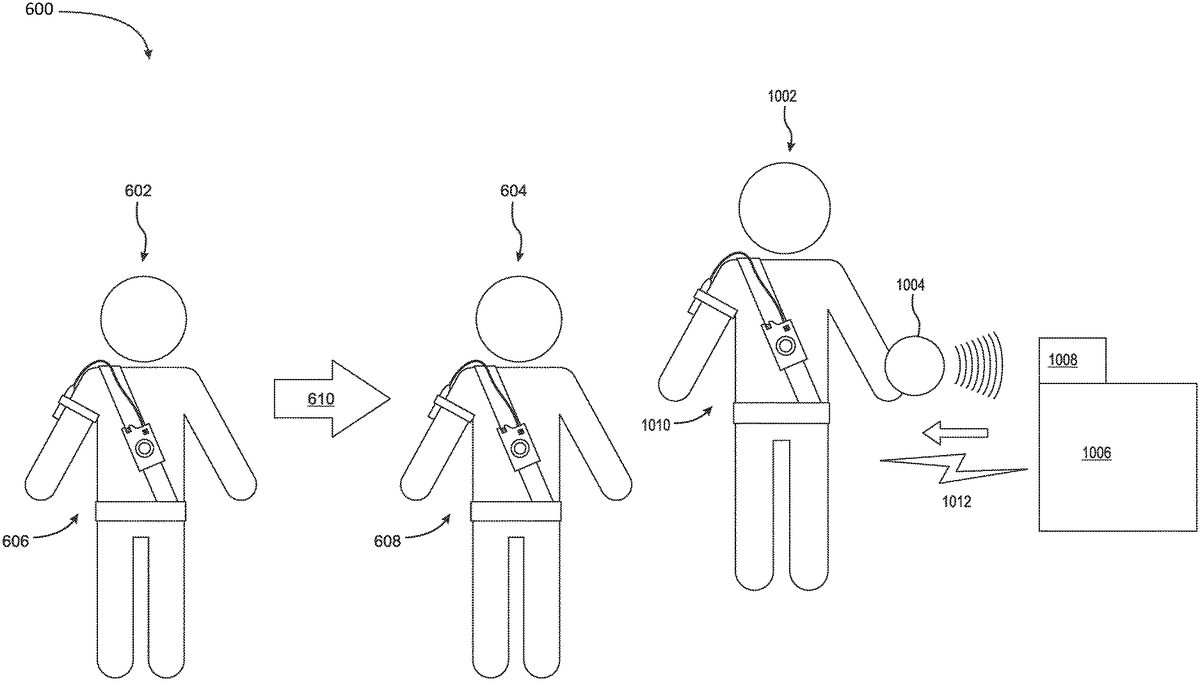
FIG. 6provides a non-limiting example of two satellite devices606,608with users602,604undergoing a state change based upon their location and trajectory relative to each other. Two users602,604are both wearing powerup tag wearable units606,608that are acting as satellite/client devices. The location and trajectory of both powerup tag wearable units606,608are monitored by powerup tag wearable units606,608. User one602, with powerup tag wearable unit one606, starts to chase610user two604, with powerup tag wearable unit two608. When the trajectory and location of powerup tag wearable unit one606, attached to user one602, relative to the user powerup tag wearable unit two608, attached to user two604meets set programmable conditions, both powerup tag wearable unit one606and powerup tag wearable unit two608generate signals instructing their respective state machines, executed on the software components114,115of their microcontrollers212, to change state.
Radio-frequency signals generated by RFID tags when detected and decoded by a RFID reader216, may cause client computer(s)/devices150,202to generate a signal instructing the state machines executed by their respective software components114,115to transition states. Severs160,302may also generate signals instructing state machines executed on at least one satellite devices150,202to transition when a RFID reader connected to RFID module306detects and decodes radio-frequencies (RF) generated by RFID tags. Servers160,302deliver the transition signal to the state machines by using network170to communicate with client computer(s)/devices150,202that execute the state machines with software components114,115. The state that the client computer(s)/device's150,202generated signal and server's160,302generated signal instruct the state machine to transition to depends on the information electronically stored on the RFID tag and embedded in the radio-frequency signal produced/generated by the RFID tag and the identity of the RFID reader216,306that detected the signal.
For non-limiting example, a RFID tag may contain a user identification number and the RFID reader that detected and decoded radio-frequency signal, containing the user identification number and generated by the RFID tag, is located on server160. Server160will use both the user identification number stored on the RFID tag and information about RFID reader that detected the information from the RFID tag, which includes the location of the RFID reader and the type of device (either a server160or a client computer/device150) that the RFID reader is connected to, to determine which state machine should transition and what state the state machine should transition to. The server160,302then uses network170to communicate with the client computer(s)/device150,202that executes the state machine(s) chosen for transition. Client computer(s)/device150,202receives the transition signal through network170and instructs the state machine executed on software components114,115to change state.
Example Embodiments
FIG. 7is a schematic diagram of the preferred embodiment's computer network700. The example embodiment includes at least two users702each wearing powerup tag wearable units202(which can be composed of either two pieces202-1or one piece202-2),704and at least one powerup tag base unit302,706. The powerup tag wearable units704are clients/satellite units and the power up tag base units706are servers/centralized units in the network170,710. The network710uses radio communication.
The powerup tag wearable units704include microcontrollers that contain instances of state machines run on software and hardware components. The powerup tag base units706monitor the powerup tag wearable units704for state changes, using radio communication, through network710. If the powerup tag base unit706detects a state change in any of the powerup tag wearable units704it broadcasts a notification signal to the network that contains information on which powerup tag wearable704unit's state machine changed state and which state the powerup tag wearable unit's704state machine transitioned to. All powerup tag wearable units704receive the notification signal and use their microcontrollers to activate I/O devices, located on powerup tag wearable units704, to notify their users702of the change.
FIG. 8is a flow diagram of diagram of the preferred process800for monitoring and reacting to a state change executed on a powerup tag base unit or other client device/computer. At step802, the powerup tag base unit monitors the client devices (e.g., the wearable powerup tag units) connected to the network for state changes using radio communication. At step804, the powerup tag base unit detects a state change in one or multiple client devices (e.g. the wearable powerup tag units). At step808, in response to detecting one or more state changes the powerup tag base unit broadcasts a notification signal through the network. The notification signal includes the identity of the client devices that changed state and the state the client devices transitioned to. The information the notification signal includes, can be relayed to users of the client devices using attached I/O devices. Finally, the powerup tag base unit returns to step802and continues to monitor the client devices.
State changes, in the preferred embodiment, can be initiated by the decoding of radio frequency signals produced by RFID tags. The RFID tags are located on glove units worn by users. The radio frequency signals produced by RFID tags contain a user identification number that identifies and is unique to the user who is wearing the glove.
FIG. 9is a schematic diagram of a glove unit containing a RFID tag. RFID tag902is located on the palm the hand of user906. RFID tag902is attached to user906using straps904. The radio frequency signals, produced by RFID tags902contain a user identification number that is paired to user906.
Both, powerup tag wearable units and powerup tag base units have RFID tag readers configured to receive and decode the radio-frequency signals produced by RFID tags. The state changing process is different based upon if the RFID tag reader that decodes the radio-frequency signal produced by a RFID tag is located on a powerup tag wearable unit or a powerup tag base unit.
If a RFID tag reader located on a powerup tag wearable unit decodes the radio-frequency signal produced by a RFID tag, the powerup tag wearable unit will receive the signal and in response change state.
This interaction simulates the tagging action of traditional tag. When a first user with a RFID tag attached to their palm “tags” a second user with a RFID tag reader connected to a powerup tag wearable unit. The second user's powerup tag wearable unit registers the signal, with a RFID tag reader, and changes state. The state change is executed on a state machine running on software and hardware components of the microcontroller located on the main unit of the powerup tag wearable unit. The state change is then detected by the powerup tag base unit who broadcasts a notification signal, via radio through the network, to all powerup tag wearable units and powerup tag base units connected to the network. The notification signal allows all powerup tag wearable units to notify, with connected I/O devices, all users that a “tag” has occurred, who gave the “tag”, and who received the “tag”.
If a RFID tag reader located on a powerup tag base unit detects and decodes the radio-frequency signal of a RFID tag, the powerup tag base unit will send a transition signal, via radio through the network, to at least one powerup tag wearable unit. In response to the transition signal, state machines executed on the microcontrollers of the powerup tag wearable unit(s) will transition states. The state change is then detected by the powerup tag base unit who broadcasts a notification signal, via radio, to all powerup tag wearable units and powerup tag base units connected to the network.
A powerup tag base unit may be one of many programmable station types. The type of station controls both which powerup tag wearable units a transition signal is sent to and what state the transition signal causes the state machines, executed by the software and hardware components of the microcontrollers in the main units of the powerup tag wearable units, to transition to.
For example, a powerup tag base unit may be a “powerup station”. A “powerup station” is programmed to send a transition signal only to the powerup tag wearable unit whose user's identification number was contained in the detected and decoded signal produced by the RFID tag.
FIG. 10is a diagram of the process of a state transition involving a “powerup station” powerup tag base unit User1002, wearing both a glove unit1004containing a RFID tag and a powerup tag wearable unit1010with an instance of a state machine running on software and hardware components of the microcontroller in the main unit, approaches powerup tag base unit1006that is a “powerup station” type. RFID tag reader1008, located on powerup tag base unit1006, decodes the radio frequency signal produced by the RFID tag on glove unit1004. Powerup tag base unit1006identifies powerup tag wearable unit1010using the user identification number contained in the radio frequency signal and sends a transition signal1012, via radio, to power tag wearable unit1010. Powerup tag wearable unit1010, in response to receiving the transition signal changes the state of its state machine. The state transition initiates process800described inFIG. 8which notifies all users of the state transition.
Another example station type is an “inversion station.” In contrast to the a “powerup station” which only sends a transition signal to the powerup tag wearable unit of the user whose identification number was contained in the decoded radio frequency signal, an “inversion” sends a transition signal to all powerup tag wearable units connected to the network.
Another example station type is a “drain station.” A drain station only sends transition signals to powerup tag wearable units whose state machines are in a specific state. A “drain station” once it detects and decodes the radio-frequency signal produced by a RFID tag will send transition signals only to powerup tag wearable units whose state machines are in the “powered up” state, causing all state machine in powered up state to transition to a different state.
Certain station types may also monitor the location and trajectory of the powerup tag wearable units, or receive location and trajectory information from the powerup tag wearable units, and only sends transition signals to powerup tag wearable units whose location and/or trajectory meets programmable conditions (e.g. a “grenade station” that only sends transition signals to powerup tag wearable units that are located within 10 meters from the power up tag base unit or a “blinding station” that only sends transition signals to powerup tag wearable units whose trajectories are moving towards the station).
The programmable nature of station types allows for a potentially limitless range of station types to be devised that can be used to initiate any combination of state transitions among any amount of powerup tag wearable units dependent on a multitude of factors including but not limited to, the location of the power up tag wearable units, the trajectory of the power up tag wearable units, the identification number contained in the decoded RFID signal, the current state of the power up tag wearable unit, or any combination of the aforementioned.
In the preferred embodiment, the powerup tag wearable units monitor how long they have stayed in a current state. If a set programmable period of time elapses while the powerup tag unit remains certain states, the power up tag wearable units change states without needing to receive a transition signal. This decaying action forces the users to continually change how they play the game and disincentivizes static gameplay.
The location and trajectory of the powerup tag wearable units are also monitored. The monitoring may be done by the powerup tag wearable units, the powerup tag base units, or both. If a powerup tag wearable units' trajectory and location relative to each other meets certain programmable conditions then the state machine executed on the microcontroller of the powerup tag wearable units will transition states.
Programmable Game Server
FIG. 11is a schematic diagram of an example embodiment's computer network1100. The network1110uses radio communication. The example embodiment includes at least two users1102each wearing powerup tag wearable units202(which can be composed of either two pieces202-1or one piece202-2, for example),1104and at least one powerup tag base unit302,1106. The powerup tag wearable units1104are clients/satellite units and the power up tag base unit1106is a server/centralized unit in the network170,1110. The example embodiment also includes a programmable game server1108(e.g., mobile telephone, tablet, or laptop computer) that is configured to, responsive to receiving radio-frequency (RF) signals, determine states of the units1104based on instructions for the interactive game, and broadcast a first and a second transition radio-frequency (RF) signal based on the determined states. The programmable game server1108can be programmed with instructions for multiple interactive games, and can include an interface configured to accept instructions for an interactive game, or an interface configured to enable a user to specify instructions for an interactive game.
The following is an example of JSON-formatted code that can be provided to the gaming server1108. The code defines the rules for two games: “domination” and “powerup tag.”
var games = {“domination”: {“teams”:“2”,“npcRoleDistribution”: “even”,“winCheck”: [“var domTeam = 0;”,“var gameOver = true;”,“for (var mac in players) {”,“var player = players[mac];”,“if (player.role==‘player’) {continue;}”,“if (player.team!=0) {”,“if (domTeam!=0 && player.team!=domTeam) {”,“gameOver = false;”,“break;”,“}”,“domTeam = player.team;”,“}”,“}”,“if (gameOver) {”,“gameOver( );”,“showTeamWin(domTeam);”,“}”],“roles”: {“player”: {“roleId”: 1,“idle”: {“color”:“self.team.color”}},“domnode”: {“roleId”: 2,“untagged”: {“color”:“#999999”,“onTag”:“self.changeState(‘tagged’);self.setTeam(tagger.team);winCheck( );”,},“tagged”: {“color”: “self.team.color”}}}},“powerup tag”: {“teams”: “0”,“npcRoleDistribution”: “even”,“winCheck”: [“var winnerCount = 0;”,“var winner = null;”,“var someOut = false;”,“for (var mac in players) {”,“var player = players[mac];”,“if (player.role!=‘player’) {continue;}”,“if (player.state == ‘tagged’) {”,“winner = null;”,“break;”,“}”,“else if (player.state == ‘idle’ || player.state == ‘powered’) {”,“winner = player;”,“winnerCount ++;”,“}”,“else if (player.state == ‘out’) {”,“someOut = true;”,“}”,“}”,“if (someOut && winnerCount == 1) {”,“gameOver( );player.showWin( );”,“}”],“roles”: {“player”: {“roleId”: 1,“idle”: {“color”:“#000099”,“showHeartbeat”:“true”,“onTag”: “if (tagger.state==‘powered_up’){self.changeState(‘tagged’);} else{tagger.showError( );} ”},“tagged”: {“color”:“#990000”,“timeout”:10000,“showHeartbeat”:“false”,“animation”:“countdown”,“onComplete”:“self.changeState(‘out’);winCheck( );”},“out”: {“color”:“rainbow”,“showHeartbeat”:“false”},“powered”: {“color”:“#990000”,“timeout”:10000,“showHeartbeat”:“false”,“animation”:“flash”,“animationSpeed”:“500”}},“powerup”: {“roleId”:3,“idle”: {“color”:“#990000”,“onTag”:“if (tagger.state == ‘idle’){tagger.changeState(‘powered’); self.showAction( );}else {self.showError( );}”}},“health”: {“roleId”:4,“idle”: {“color”:“#009900”,“onTag”:“if (tagger.state == ‘tagged’) {tagger.changeState(‘idle’);self.showAction( );} else{self.showError( );}”}}}}}
In some embodiments, the various units can all share an identical design: network communication hardware, hardware for user feedback (e.g., audio, light, and haptic), and hardware to register a near field communication (NFC) signal. In such embodiments, gameplay is not dictated by the units. Instead the units can register the presence of an NFC signal, initiate, stop, and register the expiration of a timer, and obey instructions for user feedback. All game logic is instead controlled by a separate computer system (“game server,” which can be, for example, a smart phone, tablet, laptop, or similar device. Messages are sent to the units from the separate game server and received from the units by the game server. The game server uses messages received as inputs, which it logically evaluates against a set of instructions that define the actual game play. The set of instructions can be encoded in, for example, JSON, XML, YAML, or similar formats. The game server may also have a process and mechanism for accepting new scripted instructions and adding them to the server's roster of available games. Using a scripting language or, alternatively, a graphical code construction interface, users can define their own games, install them in the game server, and execute gameplay by means of the network interaction between the units and the server. This ability adds infinite variety to the gameplay available by the combination of gaming units and the game server. In some embodiments, geographically disparate gamers can share their user-created games by way of the Internet.
The game server, state machines, and related system components may include a blockchain implementation that records transactions related to the game play. For example, transactions related to the radio-frequency identification (RFID) tag(s) configured to produce a radio-frequency (RF) signal may be recorded on a blockchain structure stored on a cloud system. On an example blockchain structure, transactions (including state transitions) related to the first satellite device and a first RFID tag reader may be recorded. Any transmissions to the game server, for example, including the radio-frequency (RF) signal produced by the RFID tag with the first RFID tag reader may be recorded in the blockchain system. Any transactions/signals transmitted or processed by any satellite devices, e.g. having a RFID tag reader, that are configured to receive, decode, and transmit to the game server the radio-frequency (RF) signal produced by the RFID tag with the second RFID tag reader may be recorded in the blockchain. The game server being configured to, responsive to receiving radio-frequency (RF) signals, determine states of the first satellite device and the second satellite device based on instructions for the interactive game, and broadcast a first and a second transition radio-frequency (RF) signal based on the determined states, and these state transitions and related transactions may be recorded in the blockchain. State transitions and transactions related to the RFID system components may be recorded on the blockchain and associated with a respective player based on a player ID, which may correspond to their respective pubic key. The RFID system components maybe represented by tokens on the blockchain. In one example, the game RFID tokens may be programmed to be responsive to game rules as they related to state changes. Each RFID token maybe linked with transactions on the blockchain representative of such state changes for each player. In one example, the Ethereum blockchain system will be used to provide a distributed ledger to record all transactions and state changes. In one example, the game tokens may be implemented using the ERC20 and ERC721 Ethereum token protocols, or the OASIS PKCS 11 token protocols. In another example, the game tokens may be associated with respective player's wallets, which are maintained by the game server. In another example, the state machines may be tokenized, and the state transitions may be written as transactions associated with each token. Because of the data integrity and immutability technical advantages provided by a blockchain, the present gaming system can benefit by providing a ledger recording state changes, that can be secure, thus increasing confidence in the game. Further, in the distributed blockchain example, the tokens recording state transitions and other transactions in the game can be further programmed with instructions and rules enabling other instances of gamers to join the game even if they are an untrusted party.
Example Implementations
While this invention has been particularly shown and described with references to example embodiments thereof, it will be understood by those skilled in the art that various changes in form and details may be made therein without departing from the scope of the invention encompassed by the appended claims.
For example, although reference is made to RFID technology, those skilled in the art will know that any kind of communication technology could be used in the context of the example embodiments, such as NFC (Near Field Communication) tag technology.
Claims
- A computing system for providing an interactive game, the computing system comprising: a programmable game server configured to enable rules of the interactive game;the programmable game server dynamically changing the rules of the interactive game in response to receiving a radio-frequency (RF) broadcast from at least one of: a first satellite device or a second satellite device;a radio-frequency identification (RFID) tag configured to produce a radio-frequency (RF) signal;the first satellite device, having a first RFID tag reader, configured to receive, decode, and transmit to the programmable game server the radio-frequency (RF) signal produced by the RFID tag with the first RFID tag reader, the first satellite device sending instructions to the programmable game server causing the rules of the interactive game to change;the second satellite device, having a second RFID tag reader, configured to receive, decode, and transmit to the programmable game server the radio-frequency (RF) signal produced by the RFID tag with the second RFID tag reader, the first satellite device sending instructions to the programmable game server causing the rules of the interactive game to change;the programmable game server being configured to, responsive to receiving radio-frequency (RF) signals, determine states of the first satellite device and the second satellite device based on the instructions for the interactive game from the first satellite device and the instructions from the second satellite device;the programmable game server broadcasting a first and a second transition radio-frequency (RF) signal based on the determined states;the first satellite device being configured to change state in response to the first transition radio-frequency (RF) signal;and the second satellite device being configured to change state in response to the second radio-frequency (RF) transition signal.
- The computing system for providing an interactive game as in claim 1 wherein the programmable game server is configured to be programmed for multiple interactive games.
- The computing system for providing an interactive game as in claim 1 wherein the programmable game server includes an interface configured to accept the instructions for the interactive game from the first satellite device and the second satellite device.
- The computing system for providing an interactive game as in claim 1 wherein the programmable game server includes an interface configured to enable a user to author and change the rules of the interactive game.
- The computing system for providing an interactive game as in claim 1 wherein the programmable game server is any of a mobile telephone, tablet, and laptop computer.
- The computing system for providing an interactive game as in claim 1 further including a centralized device, having a third RFID tag reader, configured to: receive and decode the radio-frequency (RF) signal produced by the RFID tag with the third RFID tag reader;and responsive to receiving and decoding the radio-frequency (RF) signal of the RFID tag, broadcast the first and second transition radio-frequency (RF) signals.
- The computing system for providing an interactive game as in claim 6 wherein the centralized device is in communication with the programmable game server and determines the first and second transition radio-frequency (RF) signals based on the rules for the interactive game.
- The computing system for providing an interactive game as in claim 7 wherein the centralized device is configured to monitor the first satellite device and the second satellite device for state changes, and if a state change is detected transmit a notification to the programmable game server.
- The computing system for providing an interactive game as in claim 6 wherein the programmable game server resides on the centralized device.
- A method for providing an interactive game, the method comprising: enabling the interactive game using a programmable game server;in response to receiving a radio-frequency (RF) broadcast from at least one of: a first satellite device or a second satellite device, dynamically changing rules of the interactive game using the programmable game server;producing, by a RFID tag, a radio-frequency (RF) signal;configuring, the first satellite device, having a first RFID tag reader, to receive, decode, and transmit to a programmable game server the radio-frequency (RF) signal produced by the RFID tag with the first RFID tag reader;causing the rules of the interactive game to change in response to the first satellite device sending instructions to the programmable game server;configuring, the second satellite device, having a second RFID tag reader, to receive, decode, and transmit to the programmable game server the radio-frequency (RF) signal produced by the RFID tag with the second RFID tag reader;causing the rules of the interactive game to change in response to the second satellite device sending instructions to the programmable game server;configuring the programmable game server to, responsive to receiving radio-frequency (RF) signals, determine states of the first satellite device and the second satellite device based on the instructions for the interactive game from the first satellite device and the instructions from the second satellite device, and broadcast a first and a second transition radio-frequency (RF) signal based on the determined states;transitioning state, by the first satellite device, in response to receiving the first transition radio-frequency (RF) signal;and transitioning state, by the second satellite device, in response to receiving the second radio-frequency (RF) transition signal.
- The method for providing an interactive game in claim 10 further including programming the programmable game server for multiple interactive games.
- The method for providing an interactive game in claim 10 wherein the programmable game server includes an interface configured to accept the instructions for the interactive game from the first satellite device and the instructions from the second satellite device.
- The method for providing an interactive game in claim 10 wherein the programmable game server includes an interface configured to enable a user to specify instructions for the interactive game.
- The method for providing an interactive game in claim 10 wherein the programmable game server is any of a mobile telephone, tablet, and laptop computer.
- The method for providing an interactive game in claim 10 further including configuring a centralized device, having a third RFID tag reader, to: receive and decode the radio-frequency (RF) signal produced by the RFID tag with the third RFID tag reader;and responsive to receiving and decoding the radio-frequency (RF) signal of the RFID tag, broadcast the first and second transition radio-frequency (RF) signals.
- The method for providing an interactive game in claim 15 wherein the centralized device is in communication with the programmable game server and determines the first and second transition radio-frequency (RF) signals based on the instructions for the interactive game from the first satellite device and the instructions from the second satellite device.
- The method for providing an interactive game in claim 16 further including, at the centralized device, monitoring the first satellite device and the second satellite device for state changes, and if a state change is detected transmitting a notification to the programmable game server.
- The method for providing an interactive game in claim 16 wherein the programmable game server resides on the centralized device.
- A non-transitory computer program product for providing an interactive game, the computer program product being embodied on a computer-readable medium and comprising code configured to implement rules of the interactive game so as when executed on one or more computer processers to perform operations of: dynamically changing the rules of the interactive game in response to receiving a radio-frequency (RF) broadcast from at least one of: a first satellite device or a second satellite device;producing, by a RFID tag, a radio-frequency (RF) signal;configuring, the first satellite device, having a first RFID tag reader, to receive, decode, and transmit to a programmable game server the radio-frequency (RF) signal produced by the RFID tag with the first RFID tag reader;configuring, the second satellite device, having a second RFID tag reader, to receive, decode, and transmit to the programmable game server the radio-frequency (RF) signal produced by the RFID tag with the second RFID tag reader;configuring the programmable game server to, responsive to receiving radio-frequency (RF) signals, determine states of the first satellite device and the second satellite device based on the rules for the interactive game from the first satellite device and the instructions from the second satellite device, and broadcast a first and a second transition radio-frequency (RF) signal based on the determined states;transitioning state, by the first satellite device, in response to receiving the first transition radio-frequency (RF) signal;and transitioning state, by the second satellite device, in response to receiving the second radio-frequency (RF) transition signal.
Disclaimer: Data collected from the USPTO and may be malformed, incomplete, and/or otherwise inaccurate.