U.S. Pat. No. 10,912,993
GAME CONTROLLERS AND METHODS FOR CONTROLLING A GAME CONTROLLER
AssigneeRAZER (ASIA-PACIFIC) PTE. LTD.
Issue DateMay 20, 2019
Illustrative Figure
Abstract
According to various embodiments, a game controller may be provided. The game controller may include: a controller input; a receiving portion configured to alternatively receive a first ring or a second ring, wherein the first ring allows a first range of motion of the controller input, and wherein the second ring allows a second range of motion of the controller input; a mechanical switch configured to receive mechanical input from at least one of the first ring or the second ring.
Description
DETAILED DESCRIPTION The following detailed description refers to the accompanying drawings that show, by way of illustration, specific details and embodiments in which the invention may be practiced. These embodiments are described in sufficient detail to enable those skilled in the art to practice the invention. Other embodiments may be utilized and structural, and logical changes may be made without departing from the scope of the invention. The various embodiments are not necessarily mutually exclusive, as some embodiments can be combined with one or more other embodiments to form new embodiments. In this context, the game controller as described in this description may include a memory which is for example used in the processing carried out in the game controller. A memory used in the embodiments may be a volatile memory, for example a DRAM (Dynamic Random Access Memory) or a non-volatile memory, for example a PROM (Programmable Read Only Memory), an EPROM (Erasable PROM), EEPROM (Electrically Erasable PROM), or a flash memory, e.g., a floating gate memory, a charge trapping memory, an MRAM (Magnetoresistive Random Access Memory) or a PCRAM (Phase Change Random Access Memory). In an embodiment, a “circuit” may be understood as any kind of a logic implementing entity, which may be special purpose circuitry or a processor executing software stored in a memory, firmware, or any combination thereof. Thus, in an embodiment, a “circuit” may be a hard-wired logic circuit or a programmable logic circuit such as a programmable processor, e.g. a microprocessor (e.g. a Complex Instruction Set Computer (CISC) processor or a Reduced Instruction Set Computer (RISC) processor). A “circuit” may also be a processor executing software, e.g. any kind of computer program, e.g. a computer program using a virtual machine code such as e.g. Java. Any other kind of implementation of the respective functions ...
DETAILED DESCRIPTION
The following detailed description refers to the accompanying drawings that show, by way of illustration, specific details and embodiments in which the invention may be practiced. These embodiments are described in sufficient detail to enable those skilled in the art to practice the invention. Other embodiments may be utilized and structural, and logical changes may be made without departing from the scope of the invention. The various embodiments are not necessarily mutually exclusive, as some embodiments can be combined with one or more other embodiments to form new embodiments.
In this context, the game controller as described in this description may include a memory which is for example used in the processing carried out in the game controller. A memory used in the embodiments may be a volatile memory, for example a DRAM (Dynamic Random Access Memory) or a non-volatile memory, for example a PROM (Programmable Read Only Memory), an EPROM (Erasable PROM), EEPROM (Electrically Erasable PROM), or a flash memory, e.g., a floating gate memory, a charge trapping memory, an MRAM (Magnetoresistive Random Access Memory) or a PCRAM (Phase Change Random Access Memory).
In an embodiment, a “circuit” may be understood as any kind of a logic implementing entity, which may be special purpose circuitry or a processor executing software stored in a memory, firmware, or any combination thereof. Thus, in an embodiment, a “circuit” may be a hard-wired logic circuit or a programmable logic circuit such as a programmable processor, e.g. a microprocessor (e.g. a Complex Instruction Set Computer (CISC) processor or a Reduced Instruction Set Computer (RISC) processor). A “circuit” may also be a processor executing software, e.g. any kind of computer program, e.g. a computer program using a virtual machine code such as e.g. Java. Any other kind of implementation of the respective functions which will be described in more detail below may also be understood as a “circuit” in accordance with an alternative embodiment.
In the specification the term “comprising” shall be understood to have a broad meaning similar to the term “including” and will be understood to imply the inclusion of a stated integer or step or group of integers or steps but not the exclusion of any other integer or step or group of integers or steps. This definition also applies to variations on the term “comprising” such as “comprise” and “comprises”.
The reference to any prior art in this specification is not, and should not be taken as an acknowledgement or any form of suggestion that the referenced prior art forms part of the common general knowledge in Australia (or any other country).
In order that the invention may be readily understood and put into practical effect, particular embodiments will now be described by way of examples and not limitations, and with reference to the figures.
Various embodiments are provided for devices, and various embodiments are provided for methods. It will be understood that basic properties of the devices also hold for the methods and vice versa. Therefore, for sake of brevity, duplicate description of such properties may be omitted.
It will be understood that any property described herein for a specific device may also hold for any device described herein. It will be understood that any property described herein for a specific method may also hold for any method described herein. Furthermore, it will be understood that for any device or method described herein, not necessarily all the components or steps described must be enclosed in the device or method, but only some (but not all) components or steps may be enclosed.
The term “coupled” (or “connected”) herein may be understood as electrically coupled or as mechanically coupled, for example attached or fixed, or just in contact without any fixation, and it will be understood that both direct coupling or indirect coupling (in other words: coupling without direct contact) may be provided.
Game controllers are widely used in computer games.
According to various embodiments, an enhanced game controller may be provided.
FIG. 1Ashows a game controller100according to various embodiments. The game controller100may include a controller input102(for example a thumb controller; for example a joystick). The game controller100may further include a receiving portion104configured to alternatively receive a first ring or a second ring. The first ring may allow a first range of motion of the controller input102. The second ring may allow a second range of motion of the controller input102. The game controller100may further include a mechanical switch106configured to receive mechanical input from at least one of the first ring or the second ring. The controller input102, the receiving portion104, and the mechanical switch106may be coupled with each other, like indicated by lines108, for example electrically coupled, for example using a line or a cable, and/or mechanically coupled.
In other words, different ranges of motion of a joystick of a game controller may be provided depending on whether a first ring or a second ring is attached to the game controller.
According to various embodiments, the at least one of the first ring or the second ring may include a tab configured to depress the mechanical switch106.
According to various embodiments, the at least one of the first ring or the second ring may include a tab configured to depress the mechanical switch106via an actuator.
According to various embodiments, the first ring may include a tab configured to depress the mechanical switch106via an actuator.
According to various embodiments, the second ring may be free from a tab configured to depress the mechanical switch106via an actuator.
According to various embodiments, the game controller100may be configured to transmit information indicating whether the mechanical switch106is depressed to a computing device to which the game controller100is connected.
According to various embodiments, the first ring may include a hole of a first diameter configured to surround the controller input102.
According to various embodiments, the second ring may include a hole of a second diameter configured to surround the controller input102.
According to various embodiments, the first diameter may be smaller than the second diameter.
According to various embodiments, the first range of motion may be smaller than the second range of motion.
FIG. 1Bshows a flow diagram110illustrating a method for controlling a game controller according to various embodiments. In112, a controller input may be provided. In114, a receiving portion may be provided to alternatively receive a first ring or a second ring, wherein the first ring allows a first range of motion of the controller input, and wherein the second ring allows a second range of motion of the controller input. In116, mechanical input may be received from at least one of the first ring or the second ring.
According to various embodiments, the at least one of the first ring or the second ring may include a tab configured to depress the mechanical switch.
According to various embodiments, the at least one of the first ring or the second ring may include a tab configured to depress the mechanical switch via an actuator.
According to various embodiments, the first ring may include a tab configured to depress the mechanical switch via an actuator.
According to various embodiments, the second ring may be free from a tab configured to depress the mechanical switch via an actuator.
According to various embodiments, the method may further include transmitting information indicating whether the mechanical switch is depressed to a computing device to which the game controller is connected.
According to various embodiments, the first ring may include a hole of a first diameter configured to surround the controller input.
According to various embodiments, the second ring may include a hole of a second diameter configured to surround the controller input.
According to various embodiments, the first diameter may be smaller than the second diameter.
According to various embodiments, the first range of motion may be smaller than the second range of motion.
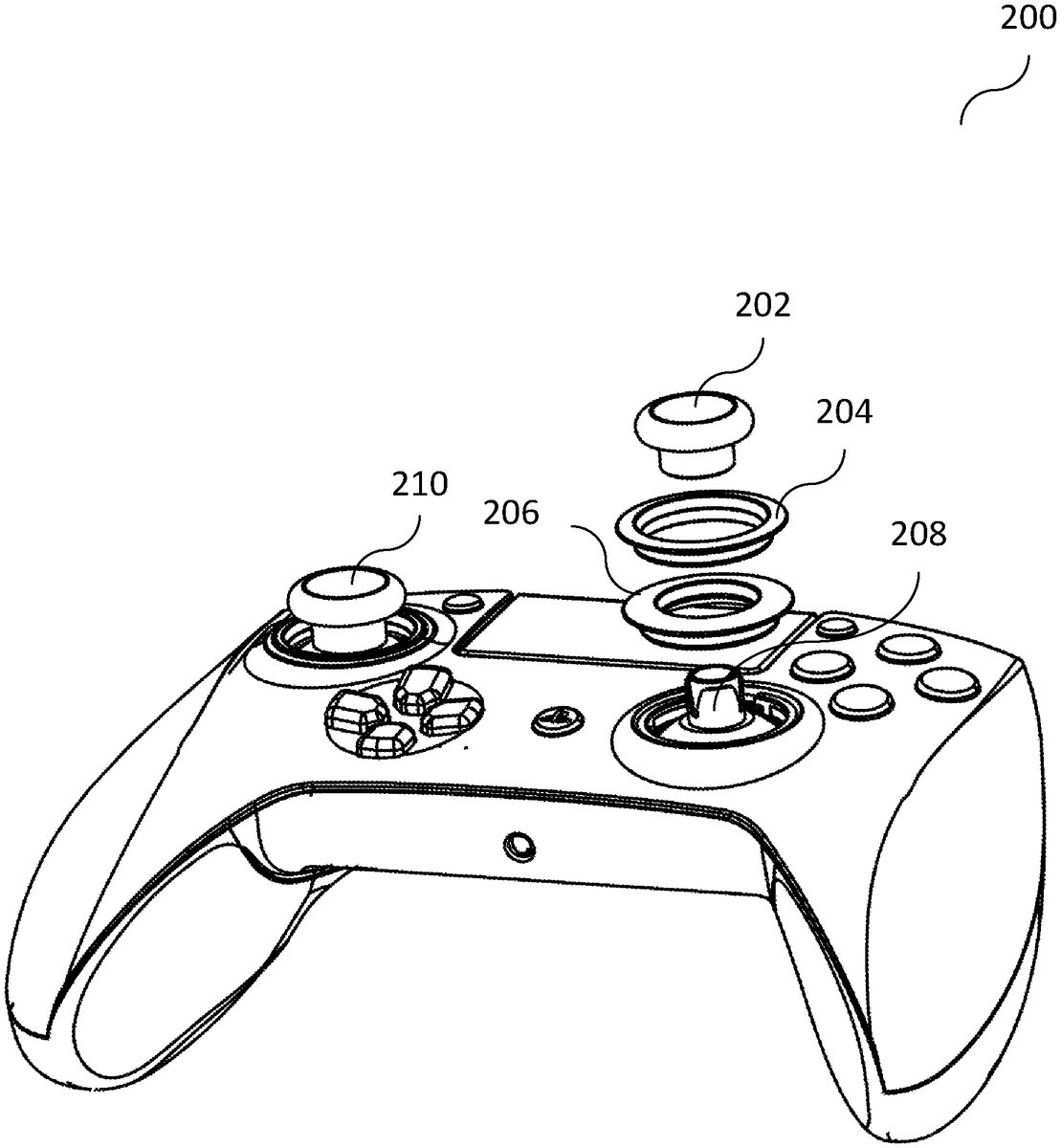
FIG. 2shows an illustration200of a game controller according to various embodiments. The game controller may include a left joystick210and a right joystick. The right joystick may include a removable thumb cap202, a large ring204(which may be replaced by a small ring206), and a counter piece208to secure the removable thumb cap202. The thumb cap202may be so called because the thumb is the one controlling the movement of the joystick and the cap may be received by the controller end. However, in an alternative embodiment, the thumb cap202may be a plunger, i.e. the thumb cap202may have a protrusion under the cap that is inserted into the controller. The right joystick may have the removable thumb cap202to be able to put a swappable ring (for example the large ring206or the small ring204) for different game sensitivity configuration.
FIG. 3shows a cross sectional view300of the game controller according to various embodiments. The removable thumb cap202may have an embedded ferromagnetic metal plate which may be attracted by a magnet302in the plunger of the joystick. The swappable rings (for example the large ring204and the small ring206) may have embedded ferromagnetic metal inserts, which may be attracted by magnets304and35in the housing of the game controller.
In other words, both the removable thumb cap202and the swappable rings may have ferromagnetic metal parts embedded on them which may be pulled by magnets302,304,306that keep them in place on the (game) controller.
FIG. 4shows an illustration400of a range of motion of the thumb cap202(and thus the joystick) according to various embodiments. Each ring may offer (or provide or allow) a different angle (in other words: a different range of motion) that gives the different sensitivity outcome on game play. For example, the small ring206may allow an angle Ø1. For example, the large ring204may provide an angle Ø2.
FIG. 5shows an illustration500of the large ring204according to various embodiments. An actuator502may be provided that activates a switch504to trigger a firmware change to recognize the shift in ring size. The large ring has no tab to push the switch504and may thus have a default firmware in use.
FIG. 6shows an illustration600of the small ring206according to various embodiments. The small ring206may have a tab602(in other words: a press tab feature) to push the switch504(via the actuator502) thereby triggering a firmware change. The actuator502may maintain pressure on the switch504so that the firmware change is maintained.
FIG. 7shows a chart700to explain how the ring size correlates the operation and sensitivity of the joystick according to various embodiments. The big ring may have a longer travel distance, it may be arbitrarily set as default for normal operation and may correspond to a default sensitivity value in the default firmware. When the large ring is replaced with a smaller ring, the user may feel the short travel required to reach the boundary (the circumference of the joystick's physical operating circle) meanwhile the tab on the smaller ring may push the switch on the PCB (printed circuit) board through an actuator and the firmware may response by scaling the operating range (from center of the circle (origin) to the circumference of the circle (Boundary)) to the smaller ring, which may effectively increase the sensitivity value to a higher sensitivity value (of for example twice the sensitivity of the default value). The gradient of the graph ofFIG. 7equates to the Sensitivity of the joystick:
Sensitivity=Gradient
If Ø2=2×Ø1
GradientG1=100/Ø1
GradientG2=100/Ø2=100/2S=50/S
Hence,G1=2×G2.
The small ring has higher sensitivity than the large ring, and the speed of operation may be faster as it takes shorter distance and hence lesser time to reach the boundary from origin.
FIG. 8shows a diagram800illustrating that the speed of operation also increases with different rings according to various embodiments as it takes a short time to reach the boundary (circumference) from the center of the circle (origin) while the output value from 0% to 100% changes correspondingly at faster rate.
According to various embodiments, when the large ring is replaced with a smaller ring, the user may feel the short travel required to reach the boundary (the circumference of the Joystick's physical operating circle); meanwhile the tab on the smaller ring may push the switch on the PCB (printed circuit board) through an actuator and the firmware may response by scaling the operating range (from center of the circle (origin) to the circumference of the circle (boundary)) to the smaller ring, which effectively may increase the sensitivity value to a higher sensitivity value (for example twice the sensitivity of the default value).
According to various embodiments, a variable sensitivity joystick may be provided. According to various embodiments, a controller variable joystick may be provided. According to various embodiments, a game controller variable sensitivity for thumbstick may be provided.
The following examples pertain to further embodiments.
Example 1 is a game controller comprising: a controller input; a receiving portion configured to alternatively receive a first ring or a second ring, wherein the first ring allows a first range of motion of the controller input, and wherein the second ring allows a second range of motion of the controller input; and a mechanical switch configured to receive mechanical input from at least one of the first ring or the second ring.
In example 2, the subject-matter of example 1 can optionally include that the at least one of the first ring or the second ring comprises a tab configured to depress the mechanical switch.
In example 3, the subject-matter of any one of examples 1 to 2 can optionally include that the at least one of the first ring or the second ring comprises a tab configured to depress the mechanical switch via an actuator.
In example 4, the subject-matter of any one of examples 1 to 3 can optionally include that the first ring comprises a tab configured to depress the mechanical switch via an actuator.
In example 5, the subject-matter of example 4 can optionally include that the second ring is free from a tab configured to depress the mechanical switch via an actuator.
In example 6, the subject-matter of any one of examples 1 to 5 can optionally include that the game controller is configured to transmit information indicating whether the mechanical switch is depressed to a computing device to which the game controller is connected.
In example 7, the subject-matter of any one of examples 1 to 6 can optionally include that the first ring comprises a hole of a first diameter configured to surround the controller input.
In example 8, the subject-matter of example 7 can optionally include that the second ring comprises a hole of a second diameter configured to surround the controller input.
In example 9, the subject-matter of example 8 can optionally include that the first diameter is smaller than the second diameter.
In example 10, the subject-matter of any one of examples 1 to 9 can optionally include that the first range of motion is smaller than the second range of motion.
Example 11 is a method for controlling a game controller, the method comprising: providing a controller input; providing a receiving portion to alternatively receive a first ring or a second ring, wherein the first ring allows a first range of motion of the controller input, and wherein the second ring allows a second range of motion of the controller input; and receiving mechanical input from at least one of the first ring or the second ring.
In example 12, the subject-matter of example 11 can optionally include that the at least one of the first ring or the second ring comprises a tab configured to depress the mechanical switch.
In example 13, the subject-matter of any one of examples 11 to 12 can optionally include that the at least one of the first ring or the second ring comprises a tab configured to depress the mechanical switch via an actuator.
In example 14, the subject-matter of any one of examples 11 to 13 can optionally include that the first ring comprises a tab configured to depress the mechanical switch via an actuator.
In example 15, the subject-matter of example 14 can optionally include that the second ring is free from a tab configured to depress the mechanical switch via an actuator.
In example 16, the subject-matter of any one of examples 11 to 15 can optionally include transmitting information indicating whether the mechanical switch is depressed to a computing device to which the game controller is connected.
In example 17, the subject-matter of any one of examples 11 to 16 can optionally include that the first ring comprises a hole of a first diameter configured to surround the controller input.
In example 18, the subject-matter of example 17 can optionally include that the second ring comprises a hole of a second diameter configured to surround the controller input.
In example 19, the subject-matter of example 18 can optionally include that the first diameter is smaller than the second diameter.
In example 20, the subject-matter of any one of examples 11 to 19 can optionally include that the first range of motion is smaller than the second range of motion.
While the invention has been particularly shown and described with reference to specific embodiments, it should be understood by those skilled in the art that various changes in form and detail may be made therein without departing from the spirit and scope of the invention as defined by the appended claims. The scope of the invention is thus indicated by the appended claims and all changes which come within the meaning and range of equivalency of the claims are therefore intended to be embraced.
Claims
- A game controller comprising: a controller input;a first ring;a second ring;a receiving portion configured to alternatively receive the first ring or the second ring, wherein the first ring allows a first range of motion of the controller input, and wherein the second ring allows a second range of motion of the controller input;and a mechanical switch configured to receive mechanical input from at least one of the first ring or the second ring;wherein the first ring comprises a tab configured to depress the mechanical switch;and wherein the second ring is free from a tab configured to depress the mechanical switch;and wherein the game controller is configured to transmit information indicating whether the mechanical switch is depressed by the tab of the first ring to a computer device to which the game controller is connected.
- The game controller of claim 1 , wherein the tab is configured to depress the mechanical switch via an actuator.
- The game controller of claim 1 , wherein the first ring comprises a hole of a first diameter configured to surround the controller input.
- The game controller of claim 3 , wherein the second ring comprises a hole of a second diameter configured to surround the controller input.
- The game controller of claim 4 , wherein the first diameter is smaller than the second diameter.
- The game controller of claim 1 , wherein the first range of motion is smaller than the second range of motion.
- The game controller of claim 1 , further comprising a printed circuit board on which the mechanical switch is provided.
- The game controller of claim 7 , wherein when mechanical switch is depressed, the printed circuit board is configured to adjust a sensitivity configuration of the controller input.
- A method for controlling a game controller, the method comprising: providing a first ring;providing a second ring;providing a controller input;providing a receiving portion to alternatively receive the first ring or the second ring, wherein the first ring allows a first range of motion of the controller input, and wherein the second ring allows a second range of motion of the controller input;and receiving mechanical input from at least one of the first ring or the second ring;wherein the first ring comprises a tab configured to depress the mechanical switch;wherein the second ring is free from a tab configured to depress the mechanical switch;and transmitting information indicating whether the mechanical switch is depressed by the tab of the first ring to a computing device to which the game controller is connected.
- The method of claim 9 , wherein the tab is configured to depress the mechanical switch via an actuator.
- The method of claim 9 , wherein the first ring comprises a hole of a first diameter configured to surround the controller input.
- The method of claim 11 , wherein the second ring comprises a hole of a second diameter configured to surround the controller input.
- The method of claim 12 , wherein the first diameter is smaller than the second diameter.
- The method of claim 9 , wherein the first range of motion is smaller than the second range of motion.
- The method of claim 9 , wherein the mechanical switch is provided on a printed circuit board.
- The method of claim 15 , wherein when mechanical switch is depressed, the printed circuit board is configured to adjust a sensitivity configuration of the controller input.
Disclaimer: Data collected from the USPTO and may be malformed, incomplete, and/or otherwise inaccurate.