U.S. Pat. No. 10,905,948
Game Controller for Hand-Held Electronic Devices having a Touch Screen Display
Issue DateApril 28, 2019
Illustrative Figure
Abstract
A game controller for use with a hand-held electronic device having a touch screen display, such as a smart phone or tablet, for more comfortably and easily playing a video game on the electronic device. The game controller has one or more control assemblies that define a securing mechanism for securing the electronic device in the game controller. In a preferred configuration, the securing mechanism clamps against the sides of the electronic device. Each control assembly has one or more screen engaging mechanisms that are configured to contact the touch screen display. The screen engaging mechanisms include a trigger that is mechanically connected to a stylus having a capacitive tip. The user can rapidly and repeatedly press the trigger to drive the tip against the touch screen display to control the game and/or one or more game objects thereof. The game controller can include one or more user handles.
Description
DETAILED DESCRIPTION OF THE PREFERRED EMBODIMENTS With reference to the figures where like elements have been given like numerical designations to facilitate the reader's understanding of the present invention, the preferred embodiments of the present invention are set forth below. The enclosed figures are illustrative of several potential preferred embodiments and, therefore, are included to represent several different ways of configuring the present invention. Although specific components, materials, configurations and uses are illustrated, it should be understood that a number of variations to the components and to the configuration of those components described herein and shown in the accompanying figures can be made without changing the scope and function of the invention set forth herein. For instance, although the description and figures included herewith generally describe and show particular materials, shapes and configurations for the various components of the new game controller of the present invention, as well as the examples of hand-held electronic devices with which the new game controller may be utilized, those skilled in the art will readily appreciate that the present invention is not so limited. In addition, the exemplary embodiments of the present game controller is shown and described herein with only those components that are required to disclose the present invention. As such, it may be possible that some of the necessary elements for attaching and using the present invention are not shown or necessarily described below, but which are well known to persons who are skilled in the relevant art. As will be readily appreciated by such persons, the various elements of the present invention that are described below may take on any form consistent with forms that are readily realized by a person of ordinary skill in the art having knowledge of video games, electronic devices and game controllers for playing video ...
DETAILED DESCRIPTION OF THE PREFERRED EMBODIMENTS
With reference to the figures where like elements have been given like numerical designations to facilitate the reader's understanding of the present invention, the preferred embodiments of the present invention are set forth below. The enclosed figures are illustrative of several potential preferred embodiments and, therefore, are included to represent several different ways of configuring the present invention. Although specific components, materials, configurations and uses are illustrated, it should be understood that a number of variations to the components and to the configuration of those components described herein and shown in the accompanying figures can be made without changing the scope and function of the invention set forth herein. For instance, although the description and figures included herewith generally describe and show particular materials, shapes and configurations for the various components of the new game controller of the present invention, as well as the examples of hand-held electronic devices with which the new game controller may be utilized, those skilled in the art will readily appreciate that the present invention is not so limited. In addition, the exemplary embodiments of the present game controller is shown and described herein with only those components that are required to disclose the present invention. As such, it may be possible that some of the necessary elements for attaching and using the present invention are not shown or necessarily described below, but which are well known to persons who are skilled in the relevant art. As will be readily appreciated by such persons, the various elements of the present invention that are described below may take on any form consistent with forms that are readily realized by a person of ordinary skill in the art having knowledge of video games, electronic devices and game controllers for playing video games.
A game controller that is configured pursuant to various embodiments of the present invention is shown generally as10inFIGS. 2-9, 11-12 and 15-40. As set forth in more detail below, the game controller10of the present invention is structured and arranged to be utilized with a hand-held electronic device12, an example of which is shown inFIGS. 1-5, 15-16, 19, 21, 23-24 and 27-28, to play a video game14, as shown inFIG. 2. Although electronic device12shown in the figures is a smart phone, persons who are skilled in the art will understand that the electronic device12can be a tablet, mini-tablet and the like having a touch screen display16in a useable screen area18of the upper surface20of the electronic device12. In addition to displaying data and other information, the touch screen display16allows the user22, shown inFIG. 1, to utilize one or more fingers24of his or her hands26to operate the electronic device12, enter data into programs, applications and the like that are operated by the electronic device12and perform a wide variety of other operations by selectively contacting the touch screen display16. The electronic device12has a case28that extends generally between a first end30and second end32and between a first side34to a second side36thereof that encloses the electronic components and defines the lower surface38of the electronic device12, as best shown inFIGS. 1-5. In many configurations, the first end30is a top end and the second end32is a bottom end of the electronic device12and the useable screen area18of the touch screen display16that is bounded on all sides by a non-touch border. The general configuration, use and operation of such hand-held electronic devices12are well known in the art.
As generally well known in the art, hand-held electronic devices12are commonly utilized to play a video game14, as shown inFIG. 1(prior art), by the user22holding onto the case28with one or more hands26and using his or her fingers24to operate the electronic device12. In addition to displaying the game video, data and other information, the touch screen display16functions as a touch-operated screen that allows the user22to move, manipulate or otherwise control one or more game objects40of the video game14. For purposes of the present invention, the video game14can be any type of computer-controlled video game or the like in which the user22utilizes one or more of his or her fingers24to control a game object40to accomplish a game objective. The game object40can be a person, animal, character, vehicle and/or any of a wide variety of inanimate objects (i.e., walls, blocks, buildings, letters and the like) that the movement thereof helps the user22to accomplish the game objective in a manner which is both fun and entertaining to the user22. In the example game14shown inFIGS. 1 and 2, the game object40is a person having one or more weapons and the game objective may be to get to a certain location to rescue a hostage, obtain an object, acquire some information or the like. As will be readily appreciated by those skilled in the art, the user/game player22uses one of his or her fingers24to move the game object40to accomplish its task.
Most video games14, particularly action-type video games14, have one or more electronic control points42in the useable screen area18of the touch screen display16of the electronic device12. Depending on the video game14, the control points42are utilized to accomplish a variety of tasks and/or to modify a game object40or objects associated with the game object, such as acquiring an item, changing levels, switching use of one weapon to another, reloading a weapon and the like. As will be readily appreciated by persons who play video games14, the control points42may be electronically positioned virtually anywhere in the useable screen area18of the touch screen display16. InFIGS. 1 and 2, the video game14has four control points, shown as42a,42b,42cand42d. When playing the video game14, the user22accesses the features represented by the control points42using his or her fingers24(which includes the thumbs) to touch the touch screen display16at the control points42. As set forth in the Background, the user22usually has to rapidly and repeatedly access the control points42while playing the video game14and to do so while he or she is also holding the electronic device12in his or her hands26, which often results in the user22having to place his or her hands26or fingers24in somewhat contorted positions. As well known in the art, the contorted positions can quickly result in his or her hands26tiring and, over time, becoming somewhat sore from playing the video game14. Such difficulty and discomfort can discourage persons from playing video games14on hand-held electronic devices12despite the availability of such devices12.
As will be readily appreciated by persons who are skilled in the art, the video game14, game object40and control points42described above and shown in the video game14ofFIGS. 1 and 2are provided for exemplary purposes only to help explain the new game controller10of the present invention. Such persons will also appreciate that the game controller10can be utilized with a wide range of different types of video games14having a wide variety of different types of game objects40and number and location of electronic control points42on the useable screen area18of the touch screen display16that the user22contacts with one of his or her fingers24while playing the video game14.
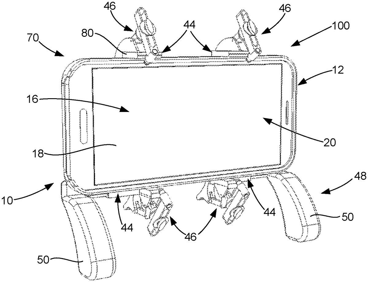
A first embodiment of the game controller10of the present invention is shown inFIGS. 2-12. In this embodiment, the game controller10has two control assemblies43aand43bthat are joined together to form the single game controller10, with the first control assembly43abeing generally toward the first end30of the electronic device12and the second control assembly43bbeing generally toward the second end32of the electronic device12when the game controller10is being utilized to play a video game14on the electronic device12, as best shown inFIG. 2. Each control assembly43a/43bgenerally comprises a device securing mechanism44for securely holding the electronic device10, a screen engaging mechanism46for engaging the touch screen display16at the control points42and a user support mechanism48that allows the user22to hold onto the game controller10separate from the electronic device12, as best shown inFIGS. 2-8 and 11-12. The user support mechanism48comprises a pair of handles50that are sized and configured to be comfortably held in the hands26of the user22while he or she is utilizing the game controller10to play the video game14. In a preferred configuration, the handles50are configured to position the touch screen display16in front of the user22as he or she plays the video game14on a hand-held electronic device12with the new game controller10of the present invention. As set forth below, in other embodiments, the new game controller10does not include the user support mechanism48.
In the embodiment of new game controller10shown inFIGS. 2-12,FIGS. 19-22andFIG. 27, the two control assemblies43a/43bare joined together to form the game controller10using a first connecting member52, a second connecting member54and a connecting mechanism56that is loosened to allow the two connecting members52/54to move relative to each other and tightened to fix the position of the two connecting members52/54relative to each other and to the electronic device12. Each of the connecting members52/54and connecting mechanism56are cooperatively sized and configured so the connecting members52/54can slide relative to each other to move the control assemblies43a/43beither closer together or further apart to accommodate different lengths (i.e., first end30to second end32) of electronic devices10. In the embodiment shown, the connecting members52/54are telescopically arranged so one of the connecting members52/54will slide in and out of the other connecting member52/54and the connecting mechanism56comprises a knob58that is threadably disposed in a slot60that engages the connecting members52/54to fix them relative to each other. In the embodiment shown in the figures, the first connecting member52slides into and out of the second connecting member54. As will be readily appreciated by persons skilled in the art, a variety of different shapes/sizes of connecting members52/54and different configurations of connecting mechanism56can be utilized to adjustably (whether slidably or not) connect the two control assemblies43a/43btogether. In the embodiments ofFIGS. 15-18andFIGS. 23-26, the control assemblies43aand43bare not joined together (forming, in effect, two separate game controllers10), but are utilized together on a single electronic device10to play a video game14.
As stated above, each control assembly43a/43bhas a device securing mechanism44that is structured and arranged to securely hold an electronic device12in a manner that allows the user22to view the touch screen display16as he or she comfortably plays a video game14. The device securing mechanism44comprises an upper body62and a lower body64that are cooperatively sized and configured to define a device receiving area66in which an electronic device12is received and to securely hold the electronic device therein during use of the game controller10of the present invention. The device securing mechanism44is structured and arranged such that the upper body62and lower body64can be spread apart to an open position68, best shown inFIGS. 6 and 9, which allows the user22to place the electronic device12into the device receiving area66or remove the electronic device12from the device receiving area66, and so the upper body62and lower body64can move towards each other to a clamping position70, best shown inFIGS. 2-5, 15-16, 19, 21, 23-24 and 27, that securely clamps the electronic device12in the device receiving area66. As will be readily appreciated by persons skilled in the art, a variety of devices can be utilized to allow the user22to easily move the device securing mechanism44between its open position68and clamping position70. For instance, the device securing mechanism44can comprise a variety of mechanical devices that allow the user22to disengage the mechanical device to place device securing mechanism44in the open position68and to engage the mechanical device to place the device securing mechanism44in its clamping position70. These mechanical devices include threaded mechanisms (such as screws, bolts and the like), detent devices, devices which are squeezed and then released, and the like. The use and operation of such mechanical devices are generally well known in the art.
For purposes of describing the present invention, the terms “upper”, “up”, “upward” or the like and the terms “lower”, “down”, “downward” and the like are utilized to refer to a direction that corresponds to the position the electronic device12is being held when it is being utilized to play a video game14in a typical up/down position in front of the user22, such as shown inFIGS. 2-5. In these figures, the first side34is the “upper” side and in contact with a portion of the upper body62and the second side36is the “lower” side and in contact with a portion of the lower body64.
In the embodiments shown in the drawings, the device securing mechanism44comprises a biasing mechanism72, as best shown inFIGS. 9-12, interconnecting the upper body62and the lower body64that, in a preferred configuration, is configured to bias the upper body62and the lower body64towards each other to place the securing mechanism in its clamping position70. The biasing mechanism72should be selected so as to have sufficient biasing force, shown as “BF” inFIG. 3, to securely clamp the upper body62against the first side34of electronic device12and the lower body64against the second side36of the electronic device12to securely hold the electronic device12in the device receiving area66of the device securing mechanism44when the user22is playing the video game14or otherwise wanting to hold the electronic device12by the game controller10. To position the electronic device12into or to remove the electronic device12from the device receiving area66, the user22spreads the upper body62and the lower body64apart by overcoming the biasing force BF of the biasing mechanism72. As such, the biasing mechanism72should not have so much biasing force BF that the user22cannot overcome the biasing force BF to move the electronic device12in and out of the device receiving area66. The configuration and use of a biasing mechanism72in the manner described above is generally well known to persons who are skilled in the relevant arts.
In a preferred configuration of the game controller10of the present invention, the biasing mechanism72of the device securing mechanism44is a spring74that interconnects the upper body62and lower body64, as best shown inFIGS. 9-12. As shown inFIGS. 9 and 10(which has a portion of the upper body62removed to illustrate the features of the biasing mechanism72) the upper body62and the lower body64are telescopically configured, with the upper body62having a biasing chamber76in which the spring74is located. The spring74interconnects the upper body62and the lower body64inside the biasing chamber76such that the lower body64will move, relative to the upper body62, generally in an upward and downward direction inside the biasing chamber76. As set forth above, movement of the lower body64relative to the upper body62results from either the biasing force BF (upward movement) from the spring74or the spreading force (downward movement) applied by the user22to place the electronic device12into or remove it from the device receiving area66. As best shown inFIG. 10, the spring74can be attached to the upper end of the upper body62and the upper end of the lower body64.
To secure the electronic device12inside the device securing area66, the upper body62and the lower body64of the device securing mechanism44comprise components that enable the game controller10to securely hold onto the electronic device10. In the embodiments shown in the figures, the upper body62has a hollow support member78that defines and encloses the biasing chamber76(except for the open lower end thereof in which the lower body64is received) and an inwardly extending upper lip member80that is attached to or integral with the upper end of the support member78so as to extend into the device receiving area66so it will abut against the first side34of the electronic device12, as best shown inFIGS. 2, 3, 5-8 and 10-12, when the game controller10is utilized with electronic device12. The lower body64has a support member82sized and configured to move upward and downward in the biasing chamber76and an inwardly extending lower lip member84that is attached to or integral with the lower end of the support member82so as to extend into the device receiving area66to abut against the second side34of the electronic device12, as shown inFIGS. 2, 6-8 and 11-12, when game controller10is utilized with electronic device12.
In the embodiment of the game controller10ofFIGS. 2-12, having the two joined control assemblies43a/43b, the lower body64also has a transversely disposed handle receiving member86that, in the embodiment shown, has an interior chamber88which is sized and configured to receive and engage a transversely disposed handle support member90, which is attached to or integral with the handle50, as best shown inFIGS. 6, 9 and 11-12. As shown in the figures, when the handle support member90is inside the interior chamber88of the handle receiving member86, the handles50extend towards the user22so he or she can use their hands26to grasp the handles50, thereby positioning the touch screen display16of the electronic device12directly in front of him or her so he or she can play the video game14on the electronic device12. In the preferred configuration, the handle receiving members86and handle support members90are cooperatively configured to allow the user22to adjust the distance between the two handles50, as may be necessary or beneficial for the comfort of the user22, and to prevent the handles50twisting relative to the control assemblies43a/43b.
The distance between the handles50can be adjusted by allowing the handle support members90(and, therefore, the handles50) to move inward and outward in the internal chamber88. Twisting of the handles50can be prevented by having the support members90be cooperatively shaped with the internal chamber88so as to prevent the support members90from pivoting (twisting) relative to the handle receiving member86. To prevent potential damage to the game controller10and/or the electronic device12from the handles50becoming disconnected, the handle support member90should securely engage the handle receiving member86and a mechanism be provided to prevent the handle support member from being pulled completely out of the internal chamber88. In one embodiment, the handle support member90can be cooperatively sized and configured with the handle receiving member86to frictionally engage the interior chamber88thereof. In other embodiments, a wide variety of mechanical connectors, including screws, bolts, pins, rods and the like, can be utilized to securely attach (with or without the interior chamber88) the handle50to the handle receiving member86. In another embodiment, the handle50is integrally formed with lower body64of the device securing mechanism46. In some configurations, this would eliminate the adjustability of the distance between the handles50. In other embodiments, the adjustability could be provided by allowing the connecting members52/54to move relative to each other and, therefore, move the handles50closer together or further apart. In any embodiment, the handles50must sufficiently engage, attach or be integral with the lower body64to allow the user22to move freely with the game controller10as he or she is playing a video game14with the hand-held electronic device12.
As set forth above, the screen engaging mechanism46is structured and arranged to be operated by the user22to contact the touch screen display16of the electronic device12at the control points42in a manner that operates or controls various aspects of the video game14, including as applicable a game object40. As will be readily appreciated by persons skilled in the art, particularly for shooter type of video games14, the screen engaging mechanism46must be configured to rapidly and repeatedly touch one or more of the control points42for the user22to be able to effectively and enjoyably play the video game14. The screen engaging mechanisms46described herein accomplishes this objective in a manner that does not require any batteries, electronic connections or the like. As set forth below, the game controller10can have a plurality of control assemblies43a/43b, each with one or more screen engaging devices46. Some embodiments of the new game controller10have a control assembly43that comprises an upper screen engaging device46aand a lower screen engaging device46b, as best shown inFIGS. 7 and 8.
The screen engaging devices46of the present invention comprise a trigger92that is mechanically connected to a capacitive stylus94(which has a capacitive tip96), as best shown inFIGS. 6-12, 16, 18, 21-22 and 24-26, such that when the user22engages the trigger92with one of his or her fingers24, the capacitive tip96of the capacitive stylus94will directed against the touch screen display16at one of the control points42, as shown inFIG. 2, to place the screen engaging device46in an engaged position98. When the user22releases the trigger92, the mechanical connection will pivot the capacitive stylus94to move the capacitive tip96thereof away from the touch screen display16, thereby placing the screen engaging device46in a disengaged position100. As will be readily appreciated by persons skilled in the art, in order for a mechanical device or object to operatively engage a touch screen display14of electronic device12, the device or object must have a capacitive tip96to engage capacitive touch screens that are utilized in hand-held electronic devices12as the touch screen display16. The capacitive tip96of a capacitive stylus94allows the touch screen display16to distinguish and sense specific touch locations that would otherwise be based on the electrical impulses in a human body (i.e., normally through the fingertip of fingers24). Capacitive touch screens do not require any significant force to be applied to the useable screen area18of the touch screen display16. As well known in the art, a capacitive stylus94has the tip96thereof selected and/or configured to provide the capacitive touch necessary to operate the touch screen display16of an electronic device12.
In a preferred embodiment of the game controller10of the present invention, each of the screen engaging mechanisms46are similarly configured. For purposes of describing the present invention, reference is made to the upper screen engaging mechanism46aof the first control assembly43a. As best shown inFIGS. 7-8 and 11-12, the trigger92is pivotally attached to a mounting member102that is attached to or integral with the upper body62of the device securing mechanism44so as to pivot relative to the upper body62when the user22engages the trigger92with one of his or her fingers24. The trigger92is also attached, typically pivotally, to a lower end of a stiff connecting rod104. The upper end of the connecting rod104is attached to a connecting arm106having a mounting surface108thereon. The mounting surface108is configured to receive the threaded mounting member110of an adjusting mechanism112, with the mounting member110extending through a slot114in a support/sliding arm116that supports the capacitive stylus94at one end thereof. Pins (not shown) are utilized to connect the trigger92to the mounting member102, the trigger92to the connecting rod104, the connecting rod104to the connecting arm106and the connecting arm106to the mounting member102. The aperture in the mounting surface108of the connecting arm106is threaded to threadably receive the mounting member110of the adjusting mechanism112, which be a knob or like device that is easy for the user22to rotate to loosen the adjusting mechanism112from the mounting surface108. When tightened into the mounting surface108, the adjusting mechanism112secures the support arm116in a desired position to place the tip96of the stylus94at the location of a control point42. The user22loosens the adjusting mechanism112to allow the support arm116to slide in and out and rotate left and right, via the slot114through which the mounting member110extends, to allow the user22to position the capacitive tip96at a control point42, which are likely to vary for different video games14. The screen engaging mechanism46is configured such that the default position (i.e., when the user22is not engaging the trigger92) is the disengaged position100. In this manner, the capacitive tip96only contacts the touch screen display16at the control point42when the user22squeezes or otherwise engages the trigger92. When the user22engages the trigger92, the trigger92will pivot to push the connecting rod104up and pivot the connecting arm106so the support arm116will drive the capacitive tip96of the capacitive stylus94against the touch screen display16. In use, the user22will be able to rapidly squeeze the trigger92with his or her finger24to make rapid, repeated contact against one of the control points42to control the video game14and/or affect one of the game objects40thereof.
With regard to the lower screen engaging mechanism46bof the first control assembly43a, the trigger92is pivotally attached to a mounting member102that is attached to or integral with the lower body64of the device securing mechanism44so as to pivot relative to the lower body64when the user22engages the trigger92with one of his or her fingers24. The trigger92is also attached, typically pivotally, to the rearward end (away from the device receiving area66) of a stiff connecting rod104. The inward end of the connecting rod104is attached to a connecting arm106having a mounting surface108thereon. The mounting surface108is configured to receive the threaded mounting member110of an adjusting mechanism112, with the mounting member110extending through a slot114in a support arm116that supports the capacitive stylus94at one end thereof. Pins (not shown) are utilized to connect the trigger92to a mounting member102, the trigger92to the connecting rod104, the connecting rod104to the connecting arm106and the connecting arm106to a second mounting member102. The aperture in the mounting surface108of the connecting arm106is threaded to threadably receive the mounting member110of the adjusting mechanism112, which may be a knob or like device that is easy for the user22to rotate to loosen the adjusting mechanism112from the mounting surface108. As described above, when tightened into the mounting surface108, the adjusting mechanism112secures the support arm116in a desired position to place the tip96of the stylus94at the location of a control point42. The user22loosens the adjusting mechanism112to allow the support arm116to slide in and out and rotate left and right, via the slot114through which the mounting member110extends, to allow the user22to position the capacitive tip96at a control point42, which are likely to vary for different video games14. The screen engaging mechanism46is configured such that the default position (i.e., when the user22not engaging the trigger92) is the disengaged position100. In this manner, the capacitive tip96only contacts the touch screen display16at the control point42when the user22squeezes or otherwise engages the trigger92. When the user22engages the trigger92, the trigger92will pivot to push the connecting rod104inward and pivot the connecting arm106so the support arm116will drive the capacitive tip96of the capacitive stylus94against the touch screen display16. As with the upper screen engaging mechanism46a, when using the lower screen engaging mechanism46bthe user22will be able to rapidly squeeze the trigger92with his or her finger24to make rapid, repeated contact against one of the control points42to control the video game14and/or affect one of the game objects40thereof.
To prevent the capacitive tip96from contacting the touch screen display16when the user22has not squeezed or otherwise engaged the trigger92, the preferred embodiment of the present invention has a trigger tensioning mechanism118that is configured to apply a biasing force to the trigger92, directly or indirectly, that will keep the capacitive tip96in spaced apart relation to the touch screen display16(i.e., keep the screen engaging mechanism46in the disengaged position100). Examples of trigger tensioning mechanisms118that can be utilized with the game controller10of the present invention are shown inFIGS. 13 and 14. In the embodiment ofFIG. 13, the trigger tensioning mechanism118comprises a torsion spring120. As shown inFIG. 13, in one configuration the coil portion122of the torsion spring120is positioned around a spring post124with the first leg126and second leg128thereof extending outward so the first leg126of the torsion spring120will be biased against a biasing post130positioned on the connecting rod104and the second leg128will be biased against a cut-out section132of the trigger92. The torsion spring120should be selected so as to bias the trigger92in a manner that will pull the connecting rod104downward and, therefore, pull the capacitive tip96of the capacitive stylus94away from the touch screen display16(i.e., the disengaged position100) when the electronic device12is in the device receiving area66. In use, the user22presses against the trigger92with sufficient force to overcome the biasing force of the torsion spring120, which will push the connecting rod104upward and drive the capacitive tip96against the touch screen display16to contact one of the control points42of the video game14.
In the embodiment ofFIG. 14, the trigger tensioning mechanism118comprises an elastic member134, such as a rubber band or the like, that is stretched between a first support post136associated with the upper body62and a second support post138associated with the connecting arm106to provide tension to the connecting arm106to push the end of the connecting arm106that connects to the connecting rod104generally upward and, as a result, keep the capacitive tip96in spaced apart relation to the touch screen display16(i.e., the disengaged position100for screen engaging mechanism46) of an electronic device12with which the game controller10is being utilized. In the embodiment ofFIG. 14, the second support post138is mounted on a tension arm140that connects to the junction of the connecting rod104and connecting arm106. The elastic member134should be selected so as to have sufficient tensile strength to provide a biasing force that will maintain the capacitive tip96in spaced apart relation to the touch screen display16(i.e., screen engaging mechanism46in its disengaged position100) until the user22applies sufficient force to the trigger92to overcome the tensile strength of the elastic member134. In use, the user22presses against the trigger92with sufficient force to overcome the biasing force of the elastic member134, which will push the connecting rod104upward and drive the capacitive tip96against the touch screen display16to contact one of the control points42of the video game14.
As will be readily appreciated by persons who are skilled in the relevant arts, a wide variety of devices may be utilized for the trigger tensioning mechanism118. For instance, the trigger tensioning mechanism118can be incorporated into the structure of the trigger92itself and/or incorporated into the connecting rod104, connecting arm106or support arm116to maintain the capacitive tip96in spaced apart relation to the touch screen display16and the screen engaging mechanism46in its disengaged position100. Any such trigger tensioning mechanism118should be configured to maintain the disengaged position100until the user22applies force to the trigger92when he or she desires the capacitive tip96to contact the touch screen display16at a control point42to affect the video game14in the desired manner (i.e., shoot a weapon). As such, the trigger tensioning mechanisms118that are described above are provided for exemplary purposes only and, except as set forth in the claims, are not intended to limit the scope of the present invention.
The embodiment of the game controller10of the present invention ofFIGS. 15-18shows use of two separate (i.e., non-attached) control assemblies43a/43b, no lower screen engaging mechanisms44and no handles50. In this embodiment, as with the above described embodiment, each control assembly43a/43bhas a device securing mechanism44that is structured and arranged to securely hold the electronic device12in the device receiving area66and a screen engaging mechanism46that is structured and arranged to rapidly and repeatedly contact the touch screen display16at the control points42. As best shown inFIGS. 16 and 17, the device securing mechanism44comprises the lower body64being telescopically received in the upper body62, with the upper body62and lower body64connected by a biasing mechanism72that securely clamps the electronic device12between the upper lip member80and lower lip member84, as best shown inFIG. 15. The screen engaging mechanisms46, which are in their disengaged position100, comprise the trigger92mechanically connected to the capacitive stylus94via the mounting member102, connecting rod104(not shown), connecting arm106, mounting surface108, support arm116and adjusting mechanism112, as best shown inFIGS. 16 and 17, to rapidly and repeatedly drive the capacitive tip96against a control point42when the user22applies pressure to the trigger92. As best shown in the back perspective view ofFIG. 16, the user22utilizes the game controller10of the embodiment ofFIGS. 15-18by holding the electronic device12in the user's hand26so his or her fingers24can operate the two triggers92to drive the capacitive tip96against the control points42at or near the first side34of the electronic device12to affect the game object40as he or she plays the video game14. Other control points42, if any, can be operated by the user22using one or more of his or her fingers24.
The embodiment ofFIGS. 19-22show a game controller10that is configured according to the present invention that has handles50, a pair of left and right control assemblies43a/43bthat are joined together to form a single unit, and no lower screen engaging mechanisms46. In this embodiment, as with the above described embodiments, each control assembly43a/43bhas a device securing mechanism44that is structured and arranged to securely hold the electronic device12in the device receiving area66and a screen engaging mechanism46that is structured and arranged to rapidly and repeatedly contact the touch screen display16at the control points42(four control points42at or near the first side34of the electronic device12). As best shown inFIGS. 20 and 21, device securing mechanism44comprises the lower body64being telescopically received in the upper body62, with the upper body62and lower body64connected by a biasing mechanism72to clamp the electronic device12between upper lip member80and lower lip member84, as best shown inFIG. 19. Though not specifically labeled in these figures, the screen engaging mechanisms46, which are in their disengaged position100, comprise the trigger92mechanically connected to the capacitive stylus94via the mounting member102, connecting rod104(not shown), connecting arm106, mounting surface108, support arm116and adjusting mechanism112, as best shown inFIGS. 20 and 22, to rapidly and repeatedly drive the capacitive tip96against a control point42when the user22applies pressure to the trigger92. In this embodiment, as with the embodiment ofFIGS. 2-12, the game controller10has the control assemblies43a/43b(which each have two screen engaging mechanisms46) joined by the connecting members52/54, as best shown inFIG. 20, and the handles50connected to the lower body64by the handle support member90being received in the internal chamber88of the handle receiving member86. The user22will play the video game14while holding the game controller10with his or her hands26and operate the triggers92with his or her fingers24to drive the capacitive tips96against the control points42to affect the game object40as he or she plays the video game14. Any control points42located at or near the second side36or the ends30/32can be operated by the user22using one or more of his or her other fingers24(i.e., thumbs).
FIGS. 23-26illustrate a fourth embodiment of the game controller10of the present invention. In this embodiment, like the second embodiment shown inFIGS. 15-18, the game controller10comprises separate control assemblies43a/43bthat are individually slid into position on the electronic device12so the capacitive tips96will contact the control points42when the user22operates the respective triggers92. Like the second embodiment, this embodiment does not utilize the handles50or the connecting members52/54or connecting mechanism56. Unlike the second embodiment, this embodiment does utilize lower screen engaging mechanisms46that will be positioned so the capacitive tips96thereof will contact control points42located at or near the second side36of the electronic device12. In this embodiment, as with the above described embodiments, each control assembly43a/43bhas a device securing mechanism44that is structured and arranged to securely hold the electronic device12in the device receiving area66and a screen engaging mechanism46that is structured and arranged to rapidly and repeatedly contact the touch screen display16at the control points42. As best shown inFIGS. 25 and 26, the device securing mechanism44comprises the lower body64being telescopically received in the upper body62, with the upper body62and lower body64being connected by a biasing mechanism72to clamp the electronic device12between the upper lip member80and lower lip member84, as best shown inFIG. 23. The screen engaging mechanisms46, which are in their disengaged position100, comprise the trigger92mechanically connected to the capacitive stylus94via the mounting member102, connecting rod104, connecting arm106, mounting surface108, support arm116and adjusting mechanism112, as best shown inFIGS. 25 and 26, to rapidly and repeatedly drive the capacitive tip96against a control point42when the user22applies pressure to the trigger92. As best shown in the back perspective view ofFIG. 24, the user22utilizes the game controller10of the embodiment ofFIGS. 23-26by holding the electronic device12the user's hand26(as with the second embodiment) so his or her fingers24can operate the two triggers92to drive the capacitive tip96against the control points42at or near the first side34of the electronic device12to affect the game object40as he or she plays the video game14.
FIG. 27shows a fifth embodiment of the game controller10of the present invention. In this embodiment, the game controller10has handles50, a pair of control assemblies43a/43bthat are connected with the first connecting member52, second connecting member54and connecting mechanism56to operate together to play a video game14on a hand-held electronic device12. The device securing mechanism44, which is configured differently than the above-described embodiments, securely holds the electronic device12in the device receiving area66between the upper body62and lower body64by clamping the upper lip member80and lower lip member84against, respectively, the first side34and second side36of the electronic device12, as shown inFIG. 27. Each control assembly43a/43bof game controller10ofFIG. 27has upper46aand lower46bscreen engaging devices that are structured and arranged to allow the user22to operate a trigger92to rapidly and repeatedly contact the touch screen display16with the capacitive tip96of a capacitive stylus94. More specifically, the game controller10ofFIG. 27comprises the same mechanical connection between the trigger92and the capacitive stylus94as described above, namely mounting member102, connecting rod104, connecting arm106, mounting surface108, support arm116, and adjusting mechanism112. As shown inFIG. 27, the upper screen engaging mechanisms46are connected to the upper body62and the lower screen engaging mechanisms46are connected to the lower body64in the manner described in the above embodiments.
The embodiment ofFIG. 27utilizes a device securing mechanism44and upper screen engaging mechanisms46that are configured differently than the above-described embodiments. In this embodiment, the connecting rod104has a plurality of apertures142that are sized and configured to receive a cooperatively sized and configured engaging pin144, as shown inFIG. 27. As above, the connecting rod104interconnects the trigger92, which is attached to the upper body62, with the connecting arm106in order to move the capacitive tip96of the capacitive stylus94against the touch screen display16. In this embodiment, the connecting rod104is also utilized as part of the device securing mechanism44. Without the engaging pin144in one of the apertures142, the user22can move the upper body62relative to the lower body64to adjust the game controller10for the size of the electronic device12to engage the upper lip member80against the first side34of the electronic device and the lower lip member84against the second side36of the electronic device12to clamp the electronic device12therebetween. When the electronic device12is tightly held in the device receiving area66, the user22places the appropriate aperture142over the engaging pin144to lock the position of the connecting rod104relative to the trigger92and tightly engage the electronic device12between the upper80and lower84lip members. The user22then tightens the connecting mechanism56to prevent further movement of the upper body62relative to the lower body64and tightly secure the electronic device12in the game controller10, as shown inFIG. 27. When the user22engages a trigger92, the downward movement of the trigger92will drive the connecting rod104upward to pivot the connecting arm106downward and drive the capacitive tip96of the capacitive stylus94against the touch screen display16to make contact with one of the control points42of the video game14so as to control a game object40or other aspect of the video game14. In the embodiment shown inFIG. 27, the lower screen engaging mechanisms46are configured in the same manner as the above-described embodiments.
A sixth embodiment of the game controller10of the present invention is shown inFIGS. 28-40. In this embodiment, the game controller10has two control assemblies43aand43bthat are joined together to form the single game controller10, with the first control assembly43abeing generally toward the first end30of the electronic device12and the second control assembly43bbeing generally toward the second end32of the electronic device12when the game controller10is being utilized to play a video game14on the electronic device12, as best shown inFIG. 2. In addition to the control assemblies43a/43b, the game controller10generally comprises a device securing mechanism44for securely holding the electronic device10, a screen engaging mechanism46for engaging the touch screen display16at the control points42and a user support mechanism48that allows the user22to hold onto the game controller10separate from the electronic device12, as best shown inFIGS. 28-38. As above, the user support mechanism48comprises a pair of handles50that are sized and configured to be comfortably held in the hands26of the user22while he or she is utilizing the game controller10to play the video game14. In a preferred configuration, the handles50are configured to position the touch screen display16of the electronic device12in front of the user22as he or she plays the video game14on the electronic device12with the new game controller10of the present invention.
The device securing mechanism44of the present embodiment of the game controller10comprises an upper body62and a lower body64that are cooperatively sized and configured to define a device receiving area66in which an electronic device12is received and to securely hold the electronic device therein during use of the game controller10of the present invention. The device securing mechanism44is structured and arranged such that the upper body62and lower body64can be spread apart to an open position68, best shown inFIGS. 29, 32, 34 and 36, which allows the user22to place the electronic device12into the device receiving area66or remove the electronic device12from the device receiving area66, and so the upper body62and lower body64can move towards each other to a closed or clamping position70(when the electronic device12is in the device receiving area66), best shown inFIGS. 28, 30-31, 33, 35 and 37-38, that either “closes” the device receiving area66or securely clamps the electronic device12therein. As will be readily appreciated by persons who are skilled in the relevant art, a variety of devices can be utilized to allow the user22to easily and quickly move the device securing mechanism44between its open position68and closed/clamping position70.
In the embodiments shown inFIGS. 28-39, the device securing mechanism44comprises a biasing mechanism72, as best shown inFIGS. 33-34, interconnecting the upper body62and the lower body64that, in a preferred configuration, is configured to bias the upper body62and the lower body64towards each other to place the securing mechanism in its closed/clamping position70. As set forth above, the biasing mechanism72should be selected so as to have sufficient biasing force, shown as “BF” inFIG. 3, to securely clamp the device securing mechanism44associated with the upper body62against the first side34of electronic device12and the device securing mechanism44associated with the lower body64against the second side36of the electronic device12to securely hold/clamp the electronic device12in the device receiving area66of the device securing mechanism44when the user22is playing the video game14or otherwise wanting to hold the electronic device12by the game controller10, as shown inFIG. 28. To position the electronic device12into or to remove the electronic device12from the device receiving area66, the user22spreads the upper body62and the lower body64apart by overcoming the biasing force BF of the biasing mechanism72. The game controller10should be configured to allow the user22to relatively spread the upper body62and lower body64apart an open distance150, shown inFIG. 34, that is sufficient to fully receive the electronic device12in the device receiving area66. As such, biasing mechanism72should not have so much biasing force BF that the user22cannot overcome the biasing force BF to move the electronic device12in and out of the device receiving area66. The configuration and use of a biasing mechanism72in the manner described above is generally well known to persons who are skilled in the relevant arts.
In a preferred configuration of the game controller10of the present invention, the biasing mechanism72of the device securing mechanism44is a spring74that interconnects the upper body62and lower body64, as best shown inFIGS. 33-34. As shown in these figures (which has a portion of the handles50removed to illustrate the features of the biasing mechanism72) the spring74interconnects the upper body62and the lower body64inside the biasing chamber76such that the upper body62will move, relative to the lower body62, generally in an upward and downward direction to, respectively, place the game controller10in its open position68or its closed/clamping position70. As set forth above, movement of the upper body62relative to the lower body64results from either the biasing force BF from the spring74(downward direction) or overcoming the biasing force BF (upward movement) by the application of a spreading force applied by the user22to place the electronic device12into or remove it from the device receiving area66. As best shown inFIGS. 33-34, the spring74is attached to the lower ends of the handles50, which are attached to or integral with the lower body64, and the upper body62via a pair of connecting members154, which are attached to or integral with the upper body62.
To secure the electronic device12inside the device securing area66, the upper body62and the lower body64of the device securing mechanism44comprise components that enable the game controller10to securely hold onto the electronic device10. In the embodiments shown in the figures, the upper body62has one or more inwardly extending upper lip members80that are attached to or integral with the upper body62and sized and configured to extend into the device receiving area66so the upper lip member(s)80will abut against the first side34of the electronic device12, as best shown inFIGS. 28-31 and 35-38, when the game controller10is utilized with electronic device12. The lower body64has one or more inwardly extending lower lip members84that are attached to or integral with the lower body64and are sized and configured to extend into the device receiving area66so as to abut against the second side34of the electronic device12, as shown inFIGS. 28-31 and 35-38, when the game controller10is utilized with an electronic device12.
In the present embodiment, components of the control assemblies43a/43bare attached to or integral with the upper body62, which is moveably engaged with the lower body64so as to allow the user22to move the upper body62upward relative to the lower body64. As best shown inFIGS. 35-38 and 40, the trigger mounting member154is attached to or integral with the upper body62. In the configuration shown in the figures, the upper body62will slide upward and downward relative to the lower body64, which is attached to or integral with the handles50of the user support mechanism48. One advantage of associating all of the triggers92of the control assemblies43a/43bwith the upper body62is with regard to use of larger sized electronic devices12with the new game controller10. As will be readily appreciated by persons who use such larger sized electronic devices12, when these electronic devices12are placed inside the device receiving area66the upper body62and lower body64will spread apart an amount that, depending on the size of the electronic device12, could be somewhat significant. If the lower triggers92where associated with the lower body64, this spread could make it difficult for the user22to comfortably operate the triggers92while playing the video game14. By having all of the triggers92associated with the upper body62(or alternatively the lower body64), the relative distance of the triggers92to each other will be maintained no matter how wide the spread between the upper body62and lower body64, as best shown with regard to the movement of the game controller10from the closed position70to the open position68shown inFIGS. 35 and 36.
As set forth above, the screen engaging mechanism46is structured and arranged to be operated by the user22to contact the touch screen display16of the electronic device12at the control points42in a manner that operates or controls various aspects of the video game14, including as applicable a game object40. The screen engaging mechanism46of the game controller10of the present embodiment is structured and arranged to rapidly and repeatedly touch one or more of the control points42so the user22can effectively and enjoyably play the video game14on the electronic device12. As with the embodiments set forth above, the screen engaging mechanisms46of the sixth embodiment is able to accomplish the desired objectives in a manner that does not require any batteries, electronic connections or the like. As set forth below, the new game controller10has a plurality of control assemblies43a/43b, each with one or more screen engaging devices46that are configured to contact the touch screen display16and engage the control points42. The control assemblies43a/43bof the new game controller10comprises an upper screen engaging device46aand a lower screen engaging device46b, as best shown inFIGS. 28-39.
The screen engaging devices46of the present invention comprise a trigger92that is mechanically connected to a capacitive stylus94(which has a capacitive tip96), as best shown inFIGS. 32-39, such that when the user22engages the trigger92with one of his or her fingers24, the capacitive tip96of the capacitive stylus94will directed against the touch screen display16at one of the control points42, as shown inFIG. 2, to place the screen engaging device46in an engaged position98, as shown inFIG. 38. When the user22releases the trigger92, the mechanical connection will pivot the capacitive stylus94to move the capacitive tip96thereof away from the touch screen display16, thereby placing the screen engaging device46in a disengaged position100, as shown inFIG. 37. As will be readily appreciated by persons skilled in the art, in order for a mechanical device or object to operatively engage a touch screen display14of electronic device12, the device or object must have a capacitive tip96to engage capacitive touch screens that are utilized in hand-held electronic devices12as the touch screen display16. As set forth above, the capacitive tip96of the capacitive stylus94allows the touch screen display16to distinguish and sense specific touch locations that would otherwise be based on the electrical impulses in a human body (i.e., normally through the fingertip of fingers24).
In a preferred embodiment of the game controller10of the present invention, each of the screen engaging mechanisms46are similarly configured. For purposes of describing the present embodiment, reference is made to the upper screen engaging mechanism46aof the second control assembly43b, which is illustrated inFIGS. 35-38. As best shown inFIGS. 29-30, 35-38 and 40, the trigger92is pivotally attached to a trigger mounting member154that is attached to or integral with the upper body62so as to pivot relative to the upper body62when the user22engages the trigger92with one of his or her fingers24. The trigger92is also attached to a proximal end of a stiff connecting arm106(which in this embodiment, is a combination of the connecting rod104and connecting arm106shown in the embodimentFIGS. 11-12). The opposite, or distal, end of the connecting arm106is attached to the screen engaging mechanism46, which is connected to the upper body62by a stylus support member156having a mounting surface108(best shown inFIGS. 11-12) thereon. The mounting surface108of the stylus support member156has an aperture that is configured to receive the threaded mounting member110of the adjusting mechanism112(also best shown inFIGS. 11-12), with the mounting member110extending through a slot114in a support/sliding arm116that supports the capacitive stylus94at one end thereof, as best shown inFIGS. 29 and 31. Pins or like elements (not specifically identified in the figures) are utilized to connect the trigger92to the trigger mounting member154, the trigger92to the connecting arm106, the connecting arm106to the stylus support member156, and the stylus support member156to a stylus mounting member158(shown inFIGS. 35-38) that is attached to or integral with the upper body member62. The aperture in the mounting surface108of the stylus support member156is threaded to threadably receive the mounting member110of the adjusting mechanism112, which be a knob or like device that is easy for the user22to rotate to loosen the adjusting mechanism112from the mounting surface108. When tightened into the aperture in the mounting surface108of the stylus support member156, the adjusting mechanism112secures the support arm116in a desired position to place the tip96of the stylus94at the location of a control point42. The user22loosens the adjusting mechanism112to allow the support arm116to slide up or down and to rotate it left and right, via the slot114through which the mounting member110extends, to allow the user22to position the capacitive tip96at a control point42, which are likely to vary for different video games14.
The screen engaging mechanism46of the present embodiment is configured such that the default position (i.e., when the user22is not engaging the trigger92) is the disengaged position100, which is in spaced apart relation to the touch screen display16of the electronic device12. In this manner, the capacitive tip96only contacts the touch screen display16at the control point42when the user22squeezes (typically) or otherwise engages the trigger92. When the user22engages the trigger92, the trigger92will pivot to push the distal end of the connecting arm106inward and pivot the stylus support member156so as to direct the capacitive tip96of the capacitive stylus94against the touch screen display16at one of the control points42thereof (the second control point42bfor the upper screen engaging mechanism46aof the second control assembly43b). In use, the user22will be able to rapidly squeeze the trigger92with his or her finger24to make rapid, repeated contact against one of the control points42to control the video game14and/or affect one of the game objects40thereof.
With regard to the other screen engaging mechanisms46, namely the upper screen engaging mechanism46aof the first control assembly43aand the two lower screen engaging mechanisms46b, preferably the components thereof are configured as set forth above for the upper screen engaging mechanism46aof the second control assembly43b. The upper screen engaging mechanism46aof the first control assembly43ais configured as described above so that the capacitive tip96thereof will selectively contact the first control point42a. With regard to the lower screen engaging mechanisms46b, the trigger92is pivotally attached to a trigger mounting member154that is attached to or integral with the upper body62, as best shown inFIGS. 32-34, so as to pivot relative to the upper body62when the user22engages the trigger92with one of his or her fingers24. As described above, the trigger92is also attached to a stiff connecting arm106(which is also a combination of the connecting rod104and connecting arm106of the embodiment ofFIGS. 11-12) that extends under the lower body64to connect at its distal end to the stylus support members156of the lower screen engaging mechanisms46b. As generally described above, the stylus support members156pivot relative to stylus mounting members158, which are attached to or integral with the lower body64, to direct the capacitive tips96of the capacitive styluses94against the touch screen display16at one or more of the lower control points42thereof (namely, the third control point42cand/or fourth control point42dfor the lower screen engaging mechanisms46b).
As set forth above, to compensate for larger sized electronic devices12, all of the triggers92are associated with the upper body62so the triggers92will maintain there respective positioning even when such electronic devices12are used with the new game controller10. As set forth above, however, the connecting arms106of the lower screen engaging mechanisms46bextend under the lower body64to interconnect the triggers92to their respective stylus mounting member158, as best shown inFIGS. 30 and 40. To avoid issues with regard to the lower connecting arms106contacting or otherwise having their movement interfered with by the lower body64when the game controller10is utilized with a larger sized electronic device12, the present invention includes a pair of slots160in the lower end of the lower body64, as best shown inFIG. 40. The slots160are sized and configured to allow the connecting arms106to move freely in response to the user22engaging the triggers50while playing the video game14. When the upper body62is moved upward to allow use of a larger sized electronic device12, the slots160will allow the connecting arms106to operate as desired without any interference by the lower body64. Specifically, engagement of the lower triggers50by the user22will cause the lower connecting arms106to properly move in response to such engagement to drive the capacitive tips96of the lower screen engaging mechanisms46bagainst the lower control points, shown as control points42c/42d, of touch screen display16.
To prevent the capacitive tip96from contacting the touch screen display16when the user22has not squeezed or otherwise engaged the trigger92, the preferred embodiment of the present invention has a trigger tensioning mechanism118that is configured to apply a biasing force to the trigger92, directly or indirectly, that will keep the capacitive tip96in spaced apart relation to the touch screen display16(i.e., keep the screen engaging mechanism46in the disengaged position100). Examples of trigger tensioning mechanisms118that can be utilized with the game controller10of the present invention is shown inFIG. 39. In the embodiment ofFIG. 39, the trigger tensioning mechanism118comprises a torsion spring120associated with each trigger92. The torsion spring120should be selected so as to bias the trigger92in a manner that will pull the distal end of the connecting arm106outward and, therefore, pull the capacitive tip96of the capacitive stylus94away from the touch screen display16(i.e., the disengaged position100) when the electronic device12is in the device receiving area66and the trigger92is not engaged by the user22. In use, the user22presses against one of the triggers92with sufficient force to overcome the biasing force of the torsion spring120, which will push the connecting arm106associated therewith inward and drive the associated capacitive tip96against the touch screen display16to contact one of the control points42of the video game14.
As will be readily appreciated by persons who are skilled in the relevant arts, a wide variety of devices may be utilized for the trigger tensioning mechanism118. For instance, the trigger tensioning mechanism118can be incorporated into the structure of the trigger92itself and/or incorporated into the connecting arm106or the support arm116to, as a default position, maintain the capacitive tip96in spaced apart relation to the touch screen display16and the screen engaging mechanism46in its disengaged position100. Any such trigger tensioning mechanism118should be configured to maintain the disengaged position100until the user22applies force to the trigger92when he or she desires the capacitive tip96to contact the touch screen display16at a control point42to affect the video game14in the desired manner (i.e., shoot a weapon). As such, the trigger tensioning mechanisms118described above are for exemplary purposes only and are not intended to limit the scope of the present invention.
In use, the user22places the hand-held electronic device12in the device receiving area66between the upper body62and lower body64sections of the new game controller10and then utilizes the device securing mechanism44to secure the electronic device in the game controller10. The control assemblies43a/43bare moved so the screen engaging mechanisms46are positioned where the capacitive tips96of each capacitive stylus94will contact a control point42of the video game14. If the control assemblies43a/43bare connected by connecting members52/54, the user22tightens the connecting mechanism56to secure the position of the screen engaging mechanisms46. To play a video game14on the electronic device12, the user22holds the game controller10by the handles50or, if the handles50are not utilized, the user22holds the electronic device12itself. When the user22engages one of the triggers92, the trigger92will pivot to push the connecting arm106in a manner such that the support arm116drives the capacitive tip96of the capacitive stylus94against the touch screen display16at the control point42. Contact by the capacitive tip96against a control point42will affect a game object40of the video game14and/or otherwise affect the video game14in a manner desired by the user22.
In the preferred configurations of the present invention, the handles50(when utilized) are ergonomically configured so as to be comfortable in the user's hands26and allow him or her to comfortably reach the triggers92with his or her fingers24. As set forth above, the game controller10can be configured with one or more control assemblies43a/43b, each with one or more screen engaging mechanisms46as may be necessary to make contact with the control points42of the video game14. In some embodiments, the user22may want or need to utilize one or more of his or her “non-trigger” fingers to directly contact one or more of the control points42that are not aligned or otherwise associated with a capacitive tip96of the game controller10. The various components of the new game controller10can be made out of a wide variety of materials. In one embodiment, the game controller10is primarily made out of a light weight, strong plastic. The portions of the game controller10that will be or are likely to be positioned in front of the useable screen area18of the touch screen display16, which is where the video game14will be displayed, are made out of a transparent material to reduce any visual interference for the user22when he or she is using the game controller10to play the video game14.
As will be readily appreciated by persons who are skilled in the art, the new game controller10allows the user22thereof to more efficiently and more comfortably play video games14on a hand-held electronic device12having a touch screen display16. In addition, the new game controller10will allow for the development of more complicated and challenging video games14due to the greater control it affords the user/player22and the additional control points42that can be handled by the user22. Because of the ability of the user22to adjust hand positions, the new game controller10should also lessen the risk of repetitive motion hand injuries.
While there are shown and described herein specific forms of the invention, it will be readily apparent to those persons who are skilled in the relevant art that the invention is not so limited, but is susceptible to various modifications and rearrangements in design and materials without departing from the spirit and scope of the invention. In particular, it should be noted that the present invention is subject to modification with regard to any dimensional relationships set forth herein and modifications in assembly, materials, size, shape and use. For instance, there are numerous components described herein that can be replaced with equivalent functioning components to accomplish the objectives of the present invention.
Claims
- A game controller for playing a video game on a hand-held electronic device having a touch screen display, said game controller comprising: at least one control assembly having a device securing mechanism and a screen engaging mechanism, said device securing mechanism structured and arranged to hold the electronic device in a device receiving area of said game controller with the touch screen display being directed toward a user who is utilizing said game controller to play the video game on the electronic device when said device securing mechanism is in a closed position and to allow the electronic device to be removed from the device receiving area when said device securing mechanism is in an open position, said device securing mechanism having an upper body moveably disposed relative to a lower body, said screen engaging mechanism having a rigid connecting arm interconnecting a trigger and a capacitive stylus supporting a capacitive tip, said trigger pivotally connected to one of said upper body and said lower body of said device securing mechanism, said capacitive stylus of said screen engaging mechanism pivotally connected to one of said upper body and said lower body, said connecting arm of said screen engaging mechanism structured and arranged to move said capacitive tip of said capacitive stylus from a disengaged position with said capacitive tip in spaced apart relation to the touch screen display to an engaged position with said capacitive tip pressed against the touch screen display when the user engages said trigger operatively connected to said capacitive tip so as to direct said capacitive tip to contact a control point of the video game and affect the video game and/or one or more game objects thereof and to move said capacitive tip back to said disengaged position when the user disengages said trigger.
- The game controller of claim 1 , wherein said device securing mechanism comprises one or more upper lip members attached to or integral with said upper body and one or more lower lip members attached to or integral with said lower body, said device receiving area being defined between said one or more upper lip members and said one or more lower lip members.
- The game controller of claim 2 further comprising a biasing mechanism interconnecting said upper body and said lower body, said biasing mechanism structured and arranged to bias said upper lip member and said lower lip member toward each other with said upper lip member against a first side of the electronic device and said lower lip member against a second side of the electronic device to clamp the electronic device between said upper lip member and said lower lip member when said game controller is utilized to hold the electronic device.
- The game controller of claim 3 further comprising a connecting member attached to one of said upper body and said lower body, said connecting member structured and arranged to interconnect said one of said upper body and said lower body to said biasing mechanism, said biasing being connected to the other of said upper body and said lower body.
- The game controller of claim 4 , wherein said connecting member is attached to or integral with said upper body and said biasing mechanism is attached to or integral with a handle that is attached to or integral with said lower body.
- The game controller of claim 1 further comprising one or more handles attached to or integrally formed with one of said upper body and said lower body of said device securing mechanism, said handles being sized and configured to be held by the user when the user is utilizing said game controller to play the video game on the electronic device.
- The game controller of claim 1 , wherein said capacitive stylus is attached to or integral with a support arm that is slidably engaged with a stylus support member connected to said connecting arm so as to allow the user to adjust the position of said capacitive tip relative to the touch screen display of the electronic device.
- The game controller of claim 7 further comprising a mounting surface associated with said stylus support member and a mounting member attached to an adjusting mechanism associated with said support arm, said mounting member disposed through a slot in said support arm so as to allow said support arm to move relative to said mounting surface and then to be clamped thereto to fixedly position said capacitive tip.
- The game controller of claim 8 , wherein said adjusting mechanism is cooperatively configured with said support arm to allow said support arm to pivot relative to said stylus support member to allow the user to place said capacitive tip of said screen engaging mechanism in corresponding position with the control point on the touch screen display of the electronic device.
- The game controller of claim 1 further comprising a trigger tensioning means associated with said screen engaging mechanism for biasing said trigger to said disengaged position so as to position said capacitive tip in spaced apart relation to the touch screen display when the user releases pressure from said trigger.
- The game controller of claim 1 , wherein said game controller comprises a first control assembly and a second control assembly, each of said first control assembly and said second control assembly having one or more of said screen engaging mechanisms.
- A game controller for playing a video game on a hand-held electronic device having a touch screen display, said game controller comprising: at least one control assembly having a device securing mechanism and one or more screen engaging mechanisms, wherein said device securing mechanism comprises an upper body having one or more upper lip members and a lower body having one or more lower lip members, said upper body and said lower body defining a device receiving area between said upper lip member and said lower lip member, said device securing mechanism structured and arranged to hold the electronic device in said device receiving area of said game controller with the touch screen display being directed toward a user who is utilizing said game controller to play the video game on the electronic device when said device securing mechanism is in a closed position with said upper lip against a first side of said electronic device and said lower lip against a second side of said electronic device and to allow the electronic device to be removed from the device receiving area when said device securing mechanism is in an open position with at least one of said upper lip members and said lower lip members being in spaced apart relation to the electronic device, wherein each of said screen engaging mechanisms comprise a trigger associated with one of said upper body and said lower body, a capacitive stylus associated with one of said upper body and said lower body and a connecting arm interconnecting said trigger and said capacitive stylus so as to operatively connect said trigger to a capacitive tip supported by said capacitive stylus, said capacitive stylus attached to or integral with a support arm that is slidably engaged with a stylus support member connected to said connecting arm so as to allow the user to adjust the position of said capacitive tip relative to the touch screen display of the electronic device, said capacitive tip configured to operatively engage the touch screen display of the electronic device, each of said trigger, said connecting arm and said capacitive stylus being structured and arranged to move said capacitive tip from a disengaged position with said capacitive tip in spaced apart relation to the touch screen display to an engaged position with said capacitive tip pressed against the touch screen display when the user applies pressure to said trigger so as to contact a control point of the video game with said capacitive tip so as to affect the video game and/or one or more game objects thereof while the user is holding said game controller and to move said capacitive tip back to said disengaged position when the user releases pressure from said trigger.
- The game controller of claim 12 further comprising a mounting surface associated with said stylus support member and a mounting member attached to an adjusting mechanism associated with said support arm, said mounting member disposed through a slot in said support arm so as to allow said support arm to move relative to said mounting surface and then to be clamped thereto to fixedly position said capacitive tip.
- The game controller of claim 13 , wherein said adjusting mechanism is cooperatively configured with said support arm to allow said support arm to pivot relative to said stylus support member to allow the user to place said capacitive tip of said screen engaging mechanism in corresponding position with the control point on the touch screen display of the electronic device.
- The game controller of claim 12 further comprising a trigger tensioning means associated with said screen engaging mechanism for biasing said trigger to said disengaged position so as to position said capacitive tip away from the touch screen display when the user releases pressure from said trigger.
- The game controller of claim 12 further comprising a biasing mechanism interconnecting said upper body and said lower body, said biasing mechanism structured and arranged to bias said upper lip member and said lower lip member toward each other with said upper lip member against the first side of the electronic device and said lower lip member against the second side of the electronic device as to clamp the electronic device between said upper lip member and said lower lip member when said game controller is utilized to hold the electronic device for playing the video game.
- The game controller of claim 16 further comprising a connecting member attached to one of said upper body and said lower body, said connecting member structured and arranged to interconnect said one of said upper body and said lower body to said biasing mechanism, said biasing mechanism being connected to the other of said upper body and said lower body.
- The game controller of claim 12 further comprising one or more handles attached to or integrally formed with one of said upper body and said lower body of said device securing mechanism, said handles being sized and configured to be held by the user when the user is utilizing said game controller to play the video game on the electronic device.
- A game controller for playing a video game on a hand-held electronic device having a touch screen display, said game controller comprising: at least one control assembly having a device securing mechanism, an upper screen engaging mechanism and a lower screen engaging mechanism;and one or more handles attached to or integral with said device securing mechanism, wherein said device securing mechanism comprises an upper body having an upper lip member and a lower body having a lower lip member, said upper body and said lower body defining a device receiving area between said upper lip member and said lower lip member, said device securing mechanism structured and arranged to hold the electronic device in said device receiving area of said game controller with the touch screen display being directed toward a user who is utilizing said game controller to play the video game on the electronic device when said device securing mechanism is in a closed position with said upper lip against a first side of said electronic device and said lower lip against a second side of said electronic device and to allow the electronic device to be removed from the device receiving area when said device securing mechanism is in an open position with at least one of said upper lip and said lower lip in spaced apart relation to the electronic device, wherein said upper screen engaging mechanism comprises a trigger associated with one of said upper body and said lower body, a capacitive stylus associated with said upper body and a connecting arm interconnecting said trigger and said capacitive stylus so as to operatively connect said trigger to a capacitive tip supported by said capacitive stylus, said capacitive tip configured to operatively engage the touch screen display of the electronic device, wherein said lower screen engaging mechanism comprises a trigger associated with one of said upper body and said lower body, a capacitive stylus associated with said lower body and a connecting arm interconnecting said trigger and said capacitive stylus so as to operatively connect said trigger to a capacitive tip supported by said capacitive stylus, said capacitive tip configured to operatively engage the touch screen display of the electronic device, wherein each of said upper screen engaging mechanism and said lower screen engaging mechanism are structured and arranged to respectively move said capacitive tip from a disengaged position with said capacitive tip in spaced apart relation to the touch screen display to an engaged position with said capacitive tip pressed against the touch screen display when the user applies pressure to said trigger so as to contact a control point of the video game with said capacitive tip so as to affect the video game and/or one or more game objects thereof while the user is holding one of said game controller and the electronic device and to move said capacitive tip back to said disengaged position when the user releases pressure from said trigger of said upper screen engaging mechanism or said lower screen engaging mechanism.
Disclaimer: Data collected from the USPTO and may be malformed, incomplete, and/or otherwise inaccurate.