U.S. Pat. No. 10,874,938
VIDEO GAME CONTROLLER
AssigneePerformance Designed Products LLC
Issue DateSeptember 17, 2019
Illustrative Figure
Abstract
A video game controller can include a body with a top surface and a bottom surface, multiple control inputs (e.g., thumbsticks, directional pads, buttons), and a face plate removably coupleable to the body over the top surface so that the plurality of control inputs extend through the face plate. One or more of the multiple control inputs are removable and replaceable without the use of tools by decoupling the face plate from the body and decoupling the control input from the body without disassembling the body.
Description
DETAILED DESCRIPTION Video game controllers can have a variety of control inputs, such as thumbsticks, directional pads, buttons (e.g., A/B/X/Y buttons), paddles, triggers, etc. to effect different functionalities while playing a video game. Each control input can have a structural interface (e.g., housing with contact surface) that a user engages and an underlying sensor module component that can be operatively (e.g., mechanically, electrically, etc.) coupled to the controller and transmits signals corresponding to the actuation of the control unit by the user to the video game console to which the controller is connected. Over time, one or both of the structural interface and the underlying sensor module component of the control inputs may malfunction or wear out. For example, with prolonged use, the structural features of control units (e.g., contact pads of thumbsticks) may wear out, become damaged, erode, or otherwise malfunction, impeding or making it difficult to utilize by a user to effectively play a video game with the controller. The embodiments described below describe video game controllers with features that advantageously facilitate the servicing and/or customization of video game controllers without requiring the disassembly of the entire controller or the use of tools. For example, such modular components (e.g., thumbsticks with different heights and/or shapes, directional pads with different shapes, sizes and/or styles, interchangeable buttons) advantageously allow the user to enhance their game playing experience by customizing the controller (e.g., based on their particular preference). FIGS. 1-8show one embodiment of a video game controller100(the “controller”). In the illustrated embodiment, the controller100can have a body102and a face plate104. Advantageously, the face plate104can readily be decoupled from the body102(e.g., without the use of tools) to expose one or more components in the body102, as further discussed below. The removable face plate104facilitates the customization of the controller100(e.g., by using face plates ...
DETAILED DESCRIPTION
Video game controllers can have a variety of control inputs, such as thumbsticks, directional pads, buttons (e.g., A/B/X/Y buttons), paddles, triggers, etc. to effect different functionalities while playing a video game. Each control input can have a structural interface (e.g., housing with contact surface) that a user engages and an underlying sensor module component that can be operatively (e.g., mechanically, electrically, etc.) coupled to the controller and transmits signals corresponding to the actuation of the control unit by the user to the video game console to which the controller is connected. Over time, one or both of the structural interface and the underlying sensor module component of the control inputs may malfunction or wear out. For example, with prolonged use, the structural features of control units (e.g., contact pads of thumbsticks) may wear out, become damaged, erode, or otherwise malfunction, impeding or making it difficult to utilize by a user to effectively play a video game with the controller. The embodiments described below describe video game controllers with features that advantageously facilitate the servicing and/or customization of video game controllers without requiring the disassembly of the entire controller or the use of tools. For example, such modular components (e.g., thumbsticks with different heights and/or shapes, directional pads with different shapes, sizes and/or styles, interchangeable buttons) advantageously allow the user to enhance their game playing experience by customizing the controller (e.g., based on their particular preference).
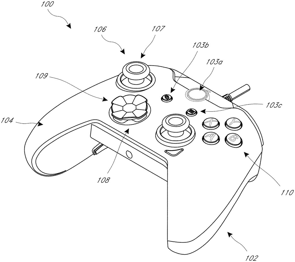
FIGS. 1-8show one embodiment of a video game controller100(the “controller”). In the illustrated embodiment, the controller100can have a body102and a face plate104. Advantageously, the face plate104can readily be decoupled from the body102(e.g., without the use of tools) to expose one or more components in the body102, as further discussed below. The removable face plate104facilitates the customization of the controller100(e.g., by using face plates with different ornamental designs). The controller100can have a plurality of control inputs that a user can actuate to effect different functionalities while playing a video game, such as one or more of the following: thumbsticks106, directional pads108, and buttons110, paddles140, triggers101, and related circuitry and componentry. In the illustrated embodiment, the controller110has two triggers101, two thumbsticks106, one directional pad108, four buttons110(e.g., A, B, X, Y buttons), a guide button103aand back/start buttons103b,103c, and be adapted for use with an Xbox® video game console. Though the illustrated embodiment, shows one trigger101(left trigger inFIG. 1A) in an extended position and one trigger101(right trigger inFIG. 1A) in a depressed position, one of skill in the art will recognize that both triggers101can optionally be depressed at the same time, or be in the extended at the same time (e.g., when not actuated by a user).
The controller100can optionally be fixedly connected to a cable that can connect to a video game console (e.g., via a USB type connector, such as a USB type A connector). In other embodiments, the controller100can have one or more female USB connectors (e.g., one or more of USB type A, USB type B, or USB type C connectors) that can receive a cable to connect to a video game console. In some embodiments, the controller100can have multiple female USB connectors to receive different types of cables to connect to a video game console.
As best shown inFIGS. 1, 1A-1B, the directional pad control input108can optionally have a cover109that can removably couple to the underlying directional pad unit111(seeFIG. 1Cwhere the cover109has been removed). The cover109can mechanically couple to the directional pad unit111. The gamer can couple different types of covers109to the directional pad unit111to customize the feel of the directional pad control input108. Similarly, the contact pad107of the thumbstick control input106can optionally be interchangeable, allowing the gamer to customize the feel of the thumbstick control input106(e.g., changing the surface shape of the contact pad107, changing the surface material of the contact pad107, changing the height of the thumbstick control input106, etc.).
FIG. 2shows the controller100with the face plate104removed, exposing a top surface112of the body102through which the control inputs are mounted. The face plate104can be removably coupled to the body102and can be readily removable (e.g., with the user's fingers, without the use of tools), which advantageously facilitates access to the components (e.g., control inputs106,108,110) without having to disassemble the controller100. The face plate104can have openings through which the control inputs106,108,110extend for the user to contact. The face plate104can optionally be mechanically coupled to the body102. For example, the face plate104can clip onto the body102(e.g., the face plate104can have one or more resilient clips that extend into slots113in the surface112). In another embodiment, the face plate104can magnetically couple to the body102. For example, the underside of the face plate104can have one or more metal portions that engage magnets (not shown) disposed on the top surface112of the body102. Alternatively, the underside of the face plate104can have one or more magnets that engage one or more metal portions disposed on the top surface112of the body102.
With reference toFIGS. 2-4, the top surface112of the body can optionally include one or more removable covers114a,114bthat cover one or more optional compartments130a,130bin the body102(e.g., in handles102a,102bof the body102). As shown inFIG. 4, the one or more compartments130a,130bcan optionally removably house vibration motors132a,132b(e.g., rumble motors, eccentric rotating mass vibration motors) that can be selectively actuated by a signal communicated to the controller100from the video game console to provide vibration feedback to the body102(e.g., provide vibration feedback to one or both of the handles102a,102bof the body102). Advantageously, the removable face plate104and optional removable covers114a,114bfacilitate the easy removal and replacement of the one or more vibration rumble motors132a,132b, such as to service existing motors or replace malfunctioning motors. Moreover, since only the face plate104and the optional covers114a,114bneed to be removed to replace the motors132a,132b, the motors132a,132bcan be easily and quickly replaced, without having to disassemble the body102of the controller100(e.g., without removing the top surface112from the rest of the body102). Additionally, the removable face plate104and optional covers114a,114ballow the modification or customization of the controller110. For example, motors with different strengths or sizes can be installed. Alternatively, the motors132a,132bcan be removed if haptic feedback provided by the vibration motors is not desired or required by the video game system being used. Optionally, the one or more compartments130a,130bcan instead house one or more weights to increase the weight of the controller100in the user's hands, as preferred by the user. In another embodiment, the one or more compartments130a,130bcan optionally be empty (e.g., not have any component disposed in them), for example if the user prefers a lighter controller100. In another embodiment, the covers114a,114bare excluded, so that compartments130a,130bcan optionally house vibration motor132a,132b, one or more weights, etc. In another embodiment, the compartments are excluded (seeFIG. 18).
FIG. 3shows the controller100with the face plate104removed to expose the top surface112of the body102. In the illustrated embodiment, the directional pad unit111has been removed, exposing the compartment116in the body102that removably receives the directional pad unit111(also shown inFIG. 6). The directional pad unit111can removably couple to the body102with a coupling mechanism, optionally a mechanical coupling mechanism.
Optionally, the directional pad unit111can removably couple to the body102via one or more clips118in the compartment116that releasably engage corresponding members (e.g., tabs, ridges, etc.) on the directional pat unit111. The directional pad unit111can optionally be aligned with features in the compartment116(e.g., alignment slot116a), and advanced linearly into the compartment116until the directional pad unit111fixedly couples to the body102(e.g., clicks or snaps into place).
Alternative mechanisms for coupling the directional pad unit111in the compartment116, such as a slot and key mechanism, a twist-lock mechanism, a threaded mechanism, can be used. In still another embodiment, the coupling mechanism can be a magnetic coupling mechanism, where one or more magnets are disposed in the compartment116or the directional pad unit111to engage one or more metal components in the directional pad unit111of the compartment116. One or more contacts120(e.g., pins) can extend into the compartment116to effect an electrical contact between the directional pad unit111and the electronics (e.g., printed circuit board) housed in the body102under the top surface112when the directional pad unit111is installed in the compartment116.
Advantageously, the removable face plate104and coupling mechanism between the directional pad unit111and the compartment116(e.g., the clips118) facilitate the removal and replacement of the directional pad unit111, such as to service the directional pad unit111or replace a malfunctioning unit111. Moreover, since only the face plate104needs to be removed to replace the directional pad unit111, the directional pad unit111can be easily and quickly replaced, without having to disassemble the body102of the controller100(e.g., without removing the top surface112from the rest of the body102).
FIG. 5shows the controller100with the face plate104removed to expose the top surface112of the body102. In the illustrated embodiment, a mechanical cover105of the thumbstick control input106has been removed, exposing the underlying thumbstick unit122and post124. The mechanical cover105can have a channel or bore (not shown) that slides over and engages (e.g., frictionally engages) the post124. Advantageously, the removable face plate104and mechanical cover105facilitate the servicing and/or modification of the thumbstick control input106. For example, different covers105can be installed on the underlying thumbstick unit122(e.g., having different shapes or materials for the contact pads107, different heights for the thumbstick, etc.). Additionally, the underlying thumbstick unit122can be serviced. Moreover, since only the face plate104needs to be removed to replace the mechanical cover105for the thumbstick control unit106, the cover105can be easily and quickly replaced, without having to disassemble the body102of the controller100(e.g., without removing the top surface112from the rest of the body102).
FIG. 7shows a back side of the controller100with a paddle unit140that can be engaged by the user's fingers to generate one or more signals that can be communicated to the video game console to effect a command in the video game. The paddle unit140can optionally be a single piece. The paddle unit140can optionally have a pair of wings142,144, where the user can generate a command signal by pressing one or both of the pair of wings142,144. A locking switch150on the body102can removably engage (e.g., lock) a member (e.g., lever) on an underside of the paddle unit140. The switch150can be actuated (e.g., slid) to unlock the paddle unit140allowing it to be removed, thereby exposing a bottom surface117of the body102that is disposed under the paddle unit140. One or more levers115a,115bcan be disposed on the bottom surface117(e.g., extending at an angle relative to the central axis of the controller100). The paddle unit140can engage the levers115a,115bwhen pressed (e.g., when one of both of the wings142,144are pressed), which can actuate one or more switches disposed within the body102under the bottom surface117. The paddle unit140can advantageously be easily replaced (e.g., with paddle units having different ornamental designs, materials or shapes), thereby further allowing for the customization of the controller100. Moreover, the ease in removing the paddle unit140allows access to the bottom of the controller100to facilitate servicing of one or more components on the underside of the controller100, such as the switches that are engaged by the levers115a,115b.
FIGS. 9-15show another embodiment of a video game controller100′ (the “controller”). The controller100′ is constructed in a similar manner as the controller100shown inFIGS. 1-8, except as noted below. Therefore, the reference numerals used to designate the various components of the controller100′ are identical to those used for identifying the corresponding components of the controller100inFIGS. 1-8, except that a “′” has been added to the reference numerals.
The controller100′ can have a body102′ and a face plate104′. Advantageously, the face plate104′ can readily be decoupled from the body102′ (e.g., without the use of tools) to expose one or more components in the body102′, as further discussed below. The removable face plate104′ facilitates the customization of the controller100′ (e.g., by using face plates with different ornamental designs). The controller100′ can have a plurality of control inputs, such as one or more of the following: thumbsticks106′, directional pads108′, and buttons110′. In the illustrated embodiment, the controller110′ has two thumbsticks106′, one directional pad108′ and a plurality of buttons110′ and be adapted for use with an Nintendo® video game console.
FIGS. 13-14shows the controller100′ with the face plate104′ removed, exposing a top surface112′ of the body102′ through which the control inputs are mounted. The face plate104′ can be removably coupled to the body102′ and can be readily removable (e.g., with the user's fingers, without the use of tools), which advantageously facilitates access to the components (e.g., control inputs106′,108′,110′) without having to disassemble the controller100′. The face plate104′ can have openings (seeFIGS. 13, 15) through which the control inputs106′,108′,110′ extend for the user to contact. The face plate104′ can optionally be mechanically coupled to the body102′. For example, the face plate104′ can clip onto the body102′ (e.g., the face plate104′ can have one or more resilient clips that extend into slots113′ in the surface112′). In another embodiment, the face plate104′ can magnetically couple to the body102′. For example, the underside of the face plate104′ can have one or more metal portions that engage magnets (not shown) disposed on the top surface112′ of the body102′. Alternatively, the underside of the face plate104′ can have one or more magnets that engage one or more metal portions disposed on the top surface112′ of the body102′.
With reference toFIGS. 13-14, the top surface112′ of the body can optionally include one or more removable covers114a′,114b′ that cover one or more compartments in the body102′ (e.g., compartments similar to compartments130a,130bin handles102a′,102b′ of the body102′). Advantageously, the removable face plate104′ and optional removable covers114a′,114b′, where present, facilitate the quick and easy removal and replacement of the one or more components in said compartments, without having to disassemble the body102′ of the controller100′ (e.g., without removing the top surface112′ from the rest of the body102′). Additionally, the removable face plate104′ and optional covers114a′,114b′ allow the modification or customization of the controller110′. For example, the one or more compartments can optionally house vibration motors or one or more weights to increase the weight of the controller100′ in the user's hands, as preferred by the user. In another embodiment, the one or more compartments can optionally be empty (e.g., not have any component disposed in them), for example if the user prefers a lighter controller100′. In another embodiment, the covers114a′,114b′ are excluded, so that empty compartments are included that can optionally house vibration motors, one or more weights, etc. In another embodiment, the compartments are excluded (seeFIG. 18).
FIG. 14shows the controller100′ with the face plate104′ removed to expose the top surface112′ of the body102′. In the illustrated embodiment, the directional pad unit111′ that includes the directional pad control input108′ is removably coupled in a compartment116′ in the body102′. The directional pad unit111′ can removably couple to the body102′ with a coupling mechanism, optionally a mechanical coupling mechanism.
Optionally, the directional pad unit111′ can removably couple to the body102′ via one or more clips118′ in the compartment116′ that releasably engage corresponding members (e.g., tabs, ridges, etc.) on the directional pat unit111′. The directional pad unit111′ can optionally be aligned with one or more features in the compartment116′ (e.g., with one or more alignment slots), and advanced linearly into the compartment116′ until the directional pad unit111′ fixedly couples to the body102′ (e.g., clicks or snaps into place).
Alternative mechanisms for coupling the directional pad unit111′ in the compartment116′, such as a slot and key mechanism, a twist-lock mechanism, a threaded mechanism, can be used. In still another embodiment, the coupling mechanism can be a magnetic coupling mechanism, where one or more magnets are disposed in the compartment116′ or the directional pad unit111′ to engage one or more metal components in the directional pad unit111′ to the compartment116′. Though not shown, one or more contacts (e.g., pins), similar to contacts120, that can extend into the compartment116′ to effect an electrical contact between the directional pad unit111′ and the electronics (e.g., printed circuit board) housed in the body102′ under the top surface112′ when the directional pad unit111′ is installed in the compartment116′.
Advantageously, the removable face plate104′ and coupling mechanism between the directional pad unit111′ and the compartment116′ (e.g., the clips118′) facilitate the removal and replacement of the directional pad unit111′, such as to service the directional pad unit111′ or replace a malfunctioning unit111′. Moreover, since only the face plate104′ needs to be removed to replace the directional pad unit111′, the directional pad unit111′ can be easily and quickly replaced, without having to disassemble the body102′ of the controller100′ (e.g., without removing the top surface112′ from the rest of the body102′). Advantageously, the directional pad unit111′ is substantially similar to the directional pad unit111, so that the same directional pad unit can be used in the controller100and the controller100′, thereby simplifying the process of replacing control units in different controllers that are adapted for use with different video game console systems.
With continued reference toFIGS. 13-14, the thumbstick input control106′ can have a mechanical cover105′ that can be removed once the face plate104′ has been decoupled from the body102′ of the controller100′. Though not shown, the mechanical cover105′ can have substantially the same shape as the mechanical cover105of the controller100, and removal of the mechanical cover105′ can expose an underlying thumbstick unit (e.g., similar to the thumbstick unit122having post124). The mechanical cover105′ can slide over and frictionally engage a post of the thumbstick unit. Advantageously, the removable face plate104′ and mechanical cover105′ facilitate the servicing and/or modification of the thumbstick control input106′. For example, different covers105′ can be installed on the underlying thumbstick unit (e.g., having different shapes or materials for the contact pads107′, different heights for the thumbstick, etc.). Additionally, the underlying thumbstick unit can be serviced. Moreover, since only the face plate104′ needs to be removed to replace the mechanical cover105′ for the thumbstick control unit106′, the cover105′ can be easily and quickly replaced, without having to disassemble the body102′ of the controller100′ (e.g., without removing the top surface112′ from the rest of the body102′).
FIG. 11shows a back side of the controller100′ with a paddle unit140′ that can be engaged by the user's fingers to generate one or more signals that can be communicated to the video game console to effect a command in the video game. The paddle unit140′ can optionally be a single piece. The paddle unit140′ can optionally have a pair of wings142′,144′, where the user can generate a command signal by pressing one or both of the pair of wings142′,144′. The paddle unit140′ is optionally removable to expose a bottom surface of the body102′ and one or more switch mechanisms (e.g., levers, such as levers115a,115bin controller100) that are actuated when the paddle unit140′ is pressed (e.g., when one or both of the wings142′,144′ are pressed) by the user, which can actuate one or more switches disposed within the body102′ under the bottom surface of the body102′. The paddle unit140′ can advantageously be easily replaced (e.g., with paddle units having different ornamental designs, materials or shapes), thereby further allowing for the customization of the controller100′. Moreover, the ease in removing the paddle unit140′ allows access to the bottom of the controller100′ to facilitate servicing of one or more components on the underside of the controller100′, such as one or more switches that are engaged by the paddle unit140′.
FIGS. 16-20show another embodiment of a video game controller100″ (the “controller”). The controller100″ is constructed in a similar manner as the controller100′ shown inFIGS. 9-15, except as noted below. Therefore, the reference numerals and description used to designate the various components of the controller100″ are identical to those used for identifying the corresponding components of the controller100′ inFIGS. 9-15, except that a “″” has been added to the reference numerals. The controller100″ can be adapted for use with a Nintendo® video game console system.
FIG. 17shows the controller100″ with the face plate104″ removed from the body102″. In the illustrated embodiment, the body102″ does not have any covers in the handles102a″,102b″ like the covers114a′,114b′ in controller100′. Additionally, the compartment116″ that receives the directional pad unit111″ has an alignment slot116a″ to facilitate aligning of the directional pad unit111″ with the compartment116″ before advancing and installing the directional pad unit111″ in the compartment116″.
FIG. 18shows the controller100″ with the face plate104″ removed from the body102″ and the directional pad unit111″ removed from the compartment116″. The compartment116″ has one or more clips118″ that releasably engage corresponding members (e.g., surfaces, tabs, ridges, etc.) on the directional pad unit111″. One or more contacts120″ (e.g., pins) can extend into the compartment116″ to effect an electrical contact between the directional pad unit111″ and the electronics (e.g., printed circuit board) housed in the body102″ under the top surface112″ when the directional pad unit111″ is installed in the compartment116″. The directional pad unit111″ is substantially similar to the directional pad unit111′,111, allowing for the use of the same directional pad unit in any of the controllers100,100′,100″.
FIGS. 19-20shows a back side of the controller100″ with a paddle unit140″ that can be engaged by the user's fingers to generate one or more signals that can be communicated to the video game console to effect a command in the video game. The paddle unit140″ can optionally be a single piece. The paddle unit140″ can optionally have a pair of wings142″,144″, where the user can generate a command signal by pressing one or both of the pair of wings142″,144″. A locking switch150″ on the body102″ can removably engage (e.g., lock) a member (e.g., lever) on an underside of the paddle unit140″. The switch150″ can be actuated (e.g., slid) to unlock the paddle unit140″ allowing it to be removed, thereby exposing a bottom surface117″ of the body102″ that is disposed under the paddle unit140″. One or more levers115a″,115b″ can be disposed on the bottom surface117″ (e.g., extending substantially perpendicular to the central axis of the controller100″). The paddle unit140″ can engage the levers115a″,115b″ (e.g., with protrusions146a″,146b″) when pressed (e.g., when one of both of the wings142″,144″ are pressed), which can actuate one or more switches disposed within the body102″ under the bottom surface117″. The paddle unit140″ can advantageously be easily replaced (e.g., with paddle units having different ornamental designs, materials or shapes), thereby further allowing for the customization of the controller100″. Moreover, the ease in removing the paddle unit140″ allows access to the bottom of the controller100″ to facilitate servicing of one or more components on the underside of the controller100″, such as the switches that are engaged by the levers115a″,115b″. As best shown inFIG. 20, the paddle unit140″ can have protrusions147a″,147b″,147c″ that allow it to couple to the body102″ (e.g., couple to openings in the bottom surface117″).
Advantageously, the video game controller100,100′,100″ has various features that facilitate the serviceability of the controller100,100′,100″, thereby facilitating repairs to controllers (e.g., when one or more input controls are malfunctioning or have worn out) and inhibiting the need to buy a new controller which can be a significant expense. Additionally, the controller100,100′,100″ has a removable face plate104,104′,104″ that allows access to the control inputs (e.g., thumbsticks106,106′,106″; directional pads108,108′,108″; buttons110,110′,110″) to service or modify them (e.g., replace them with control inputs having different shapes, heights, materials, etc.). Further, the removable/replaceable control units (e.g., thumbstick mechanical covers105,105′,105″, directional pad units111,111′,111″, etc.) in the controllers100,100′,100″ are advantageously substantially similar in shape, allowing the same control input (e.g., thumbsticks106,106′,106″; directional pads108,108′,108″; buttons110,110′,110″) to be used in any controller100,100′,100″, thereby avoiding having to purchase or use different directional pad control inputs108,108′,108″ for the different controllers100,100′,100″, thereby simplifying the serviceability of the controllers100,100′,100″. Additionally, the removable paddle unit140,140′,140″ can advantageously facilitate the adjustment of the operability of one or more control inputs. In one embodiment, the travel of the triggers101,101′ can be mechanically adjusted, for example by moving (e.g., sliding) a switch or lever119a,119baccessible by removing the paddle unit140,140′, where the switch or lever119a,119bis mechanically coupled to the trigger mechanism, thereby allowing the user to adjust the travel motion of the trigger required to generate the signal (e.g., “shot” signal) to the video game console. Optionally, the removable cover or paddle unit140,140′,140″ (e.g., when decoupled from the body102,102′,102″) allows the trigger stops (actuated by the switch or lever119a,119b) to be engaged, disengaged or removed completely. Optionally, one or more of the switch or lever119a,119bcan be removed and/or replaced when the removable cover or paddle unit140,140′,140″ is decoupled from the body102,102′,102″.
While certain embodiments of the inventions have been described, these embodiments have been presented by way of example only, and are not intended to limit the scope of the disclosure. Indeed, the novel methods and systems described herein may be embodied in a variety of other forms. Furthermore, various omissions, substitutions and changes in the systems and methods described herein may be made without departing from the spirit of the disclosure. The accompanying claims and their equivalents are intended to cover such forms or modifications as would fall within the scope and spirit of the disclosure. Accordingly, the scope of the present inventions is defined only by reference to the appended claims.
Features, materials, characteristics, or groups described in conjunction with a particular aspect, embodiment, or example are to be understood to be applicable to any other aspect, embodiment or example described in this section or elsewhere in this specification unless incompatible therewith. All of the features disclosed in this specification (including any accompanying claims, abstract and drawings), and/or all of the steps of any method or process so disclosed, may be combined in any combination, except combinations where at least some of such features and/or steps are mutually exclusive. The protection is not restricted to the details of any foregoing embodiments. The protection extends to any novel one, or any novel combination, of the features disclosed in this specification (including any accompanying claims, abstract and drawings), or to any novel one, or any novel combination, of the steps of any method or process so disclosed.
Furthermore, certain features that are described in this disclosure in the context of separate implementations can also be implemented in combination in a single implementation. Conversely, various features that are described in the context of a single implementation can also be implemented in multiple implementations separately or in any suitable subcombination. Moreover, although features may be described above as acting in certain combinations, one or more features from a claimed combination can, in some cases, be excised from the combination, and the combination may be claimed as a subcombination or variation of a subcombination.
Moreover, while operations may be depicted in the drawings or described in the specification in a particular order, such operations need not be performed in the particular order shown or in sequential order, or that all operations be performed, to achieve desirable results. Other operations that are not depicted or described can be incorporated in the example methods and processes. For example, one or more additional operations can be performed before, after, simultaneously, or between any of the described operations. Further, the operations may be rearranged or reordered in other implementations. Those skilled in the art will appreciate that in some embodiments, the actual steps taken in the processes illustrated and/or disclosed may differ from those shown in the figures. Depending on the embodiment, certain of the steps described above may be removed, others may be added. Furthermore, the features and attributes of the specific embodiments disclosed above may be combined in different ways to form additional embodiments, all of which fall within the scope of the present disclosure. Also, the separation of various system components in the implementations described above should not be understood as requiring such separation in all implementations, and it should be understood that the described components and systems can generally be integrated together in a single product or packaged into multiple products.
For purposes of this disclosure, certain aspects, advantages, and novel features are described herein. Not necessarily all such advantages may be achieved in accordance with any particular embodiment. Thus, for example, those skilled in the art will recognize that the disclosure may be embodied or carried out in a manner that achieves one advantage or a group of advantages as taught herein without necessarily achieving other advantages as may be taught or suggested herein.
Conditional language, such as “can,” “could,” “might,” or “may,” unless specifically stated otherwise, or otherwise understood within the context as used, is generally intended to convey that certain embodiments include, while other embodiments do not include, certain features, elements, and/or steps. Thus, such conditional language is not generally intended to imply that features, elements, and/or steps are in any way required for one or more embodiments or that one or more embodiments necessarily include logic for deciding, with or without user input or prompting, whether these features, elements, and/or steps are included or are to be performed in any particular embodiment.
Conjunctive language such as the phrase “at least one of X, Y, and Z,” unless specifically stated otherwise, is otherwise understood with the context as used in general to convey that an item, term, etc. may be either X, Y, or Z. Thus, such conjunctive language is not generally intended to imply that certain embodiments require the presence of at least one of X, at least one of Y, and at least one of Z.
Language of degree used herein, such as the terms “approximately,” “about,” “generally,” and “substantially” as used herein represent a value, amount, or characteristic close to the stated value, amount, or characteristic that still performs a desired function or achieves a desired result. For example, the terms “approximately”, “about”, “generally,” and “substantially” may refer to an amount that is within less than 10% of, within less than 5% of, within less than 1% of, within less than 0.1% of, and within less than 0.01% of the stated amount. As another example, in certain embodiments, the terms “generally parallel” and “substantially parallel” refer to a value, amount, or characteristic that departs from exactly parallel by less than or equal to 15 degrees, 10 degrees, 5 degrees, 3 degrees, 1 degree, or 0.1 degree.
The scope of the present disclosure is not intended to be limited by the specific disclosures of preferred embodiments in this section or elsewhere in this specification, and may be defined by claims as presented in this section or elsewhere in this specification or as presented in the future. The language of the claims is to be interpreted broadly based on the language employed in the claims and not limited to the examples described in the present specification or during the prosecution of the application, which examples are to be construed as non-exclusive.
Of course, the foregoing description is that of certain features, aspects and advantages of the present invention, to which various changes and modifications can be made without departing from the spirit and scope of the present invention. Moreover, the invention need not feature all of the objects, advantages, features and aspects discussed above. Thus, for example, those of skill in the art will recognize that the invention can be embodied or carried out in a manner that achieves or optimizes one advantage or a group of advantages as taught herein without necessarily achieving other objects or advantages as may be taught or suggested herein. In addition, while a number of variations of the invention have been shown and described in detail, other modifications and methods of use, which are within the scope of this invention, will be readily apparent to those of skill in the art based upon this disclosure. It is contemplated that various combinations or subcombinations of these specific features and aspects of embodiments may be made and still fall within the scope of the invention. Accordingly, it should be understood that various features and aspects of the disclosed embodiments can be combined with or substituted for one another in order to form varying modes of the discussed controllers.
Claims
- A video game controller, comprising: a controller body having a top surface and a bottom surface and a pair of handles;a plurality of control inputs comprising one or more thumbsticks, one or more of the plurality of control inputs removably mounted on the controller body through the top surface to releasably connect with electronics disposed within the controller body below the top surface of the controller body, each of the plurality of control inputs operable to control one or more operations of the video game controller;a face plate having a plurality of openings and being removably coupleable to the controller body so that the plurality of control inputs extend through the plurality of openings in the face plate when the face plate is coupled to the controller body;and a detachable paddle unit removably coupled to an underside of the controller body, one or more portions of the paddle unit being movable relative to the bottom surface of the controller body, wherein one or more of the plurality of control inputs are removable and replaceable by decoupling the face plate from the controller body and decoupling said one or more of the plurality of control inputs from the controller body without disassembling the controller body.
- The video game controller of claim 1 , wherein the plurality of control inputs comprises one or more directional pads and one or more buttons.
- The video game controller of claim 1 , wherein the one or more thumbsticks are interchangeable thumbsticks having different heights or shapes.
- The video game controller of claim 1 , wherein said one or more of the plurality of control inputs are mechanically coupled to the controller body.
- The video game controller of claim 1 , wherein said one or more of the plurality of control inputs is installed by aligning the control input with a compartment in the controller body and linearly advancing the control input into the compartment.
- The video game controller of claim 1 , further comprising one or more depressible triggers coupled to a front surface of the controller body, the one or more depressible triggers having an adjustable travel distance.
- The video game controller of claim 6 , further comprising one or more movable levers actuatable to adjust the travel distance of the one or more depressible triggers.
- The video game controller of claim 7 , wherein the one or more movable levers are configured to slide relative to the bottom surface of the controller body to adjust the travel distance of the one or more depressible triggers.
- The video game controller of claim 1 , wherein a protrusion of the paddle unit selectively engages a portion of the controller body to couple the paddle unit to the controller body, the protrusion configured to selectively disengage from the controller body to allow the paddle unit to be detached from the controller body.
- The video game controller of claim 1 , wherein the face plate is magnetically coupled to the controller body.
- A video game controller kit, comprising: a video game controller comprising a controller body having a top surface and a bottom surface and a pair of handles, a plurality of control inputs comprising one or more thumbsticks, one or more of the plurality of control inputs removably mounted on the controller body through the top surface to releasably connect with electronics disposed within the controller body below the top surface of the controller body, each of the plurality of control inputs operable to control one or more operations of the video game controller, a face plate having a plurality of openings and being removably coupleable to the controller body so that the plurality of control inputs extend through the plurality of openings in the face plate when the face plate is coupled to the controller body, and a detachable paddle unit removably coupled to an underside of the controller body, one or more portions of the paddle unit being movable relative to the bottom surface of the controller body;and a plurality of replacement control inputs configured to replace one or more of the plurality of control inputs, wherein one or more of the plurality of control inputs are removable and replaceable by decoupling the face plate from the controller body and decoupling said one or more of the plurality of control inputs from the controller body without disassembling the controller body.
- The video game controller of claim 11 , wherein the plurality of control inputs comprises one or more directional pads and one or more buttons.
- The video game controller of claim 11 , wherein the one or more thumbsticks are interchangeable thumbsticks having different heights or shapes.
- The video game controller of claim 11 , wherein said one or more of the plurality of control inputs are mechanically coupled to the controller body.
- The video game controller of claim 11 , wherein said one or more of the plurality of control inputs is installed by aligning the control input with a compartment in the controller body and linearly advancing the control input into the compartment.
- The video game controller of claim 11 , further comprising one or more depressible triggers coupled to a front surface of the controller body, the one or more depressible triggers having an adjustable travel distance.
- The video game controller of claim 16 , further comprising one or more movable switches actuatable to adjust the travel distance of the one or more depressible triggers.
- The video game controller of claim 17 , wherein the one or more movable levers are configured to slide relative to the bottom surface of the controller body to adjust the travel distance of the one or more depressible triggers.
- The video game controller of claim 11 , wherein a protrusion of the paddle unit selectively engages a portion of the controller body to couple the paddle unit to the controller body, the protrusion configured to selectively disengage from the controller body to allow the paddle unit to be detached from the controller body.
- The video game controller of claim 11 , wherein the face plate is magnetically coupled to the controller body.
Disclaimer: Data collected from the USPTO and may be malformed, incomplete, and/or otherwise inaccurate.