U.S. Pat. No. 10,857,455
SPECTATOR MANAGEMENT AT VIEW LOCATIONS IN VIRTUAL REALITY ENVIRONMENTS
AssigneeSony Interactive Entertainment Inc
Issue DateApril 1, 2019
Illustrative Figure
Abstract
A method is provided, including: providing a first view of a virtual environment to a first HMD, the first view having a first view direction towards a virtual object, the first view being from a first-person perspective positioned at the first location; simultaneously, providing a second view to a second HMD, the second view being from a first-person perspective positioned at the first location, and rendering in the second view a virtual character associated to the first view, the rendering configured to present the virtual character as being positioned at a second location, and configured to present the virtual character having a second view direction adjusted relative to the first view direction so as to be from a first-person perspective of the virtual character as the virtual character is positioned at the second location, and so as to be towards the virtual object as shown in the second view.
Description
DETAILED DESCRIPTION The following implementations of the present disclosure provide methods, systems, computer readable media and cloud systems, for providing HMD spectators of a virtual environment (e.g. a gaming environment) with customized views that improve the experience of the spectators. More specifically, in accordance with implementations of the disclosure, spectators are able to view the virtual environment from the same, or substantially the same, viewing location, yet also be provided with rendering of other spectators, such as their friends, in their vicinity in the virtual environment. The viewing location can be a predefined viewing location that may be a preferred or optimal viewing location. Thus, each spectator is able to experience substantially the same vantage point in the virtual environment, while also being provided with the sensation that they are surrounded by other spectators, even as each of the other spectators is also provided with the same vantage point in the virtual environment and sensation of being surrounded by other spectators. A predefined viewing location within the virtual reality environment can draw the attention of spectators to view or focus on interesting content within the virtual environment, which for example may be a virtual reality scene of a video game, e.g. as navigated by an HMD player. It will be appreciated that there may be more than one viewing location which may be predefined at different areas of a game, content, multimedia, or generally content being navigated by the (e.g. HMD) player. In various implementations, the methods, systems, image capture objects, sensors and associated interface objects (e.g., gloves, controllers, etc.) are configured to process data that is configured to be rendered in substantial real time on a display screen. The display may be the display of a head mounted display (HMD), a display of a second screen, a display of ...
DETAILED DESCRIPTION
The following implementations of the present disclosure provide methods, systems, computer readable media and cloud systems, for providing HMD spectators of a virtual environment (e.g. a gaming environment) with customized views that improve the experience of the spectators. More specifically, in accordance with implementations of the disclosure, spectators are able to view the virtual environment from the same, or substantially the same, viewing location, yet also be provided with rendering of other spectators, such as their friends, in their vicinity in the virtual environment. The viewing location can be a predefined viewing location that may be a preferred or optimal viewing location. Thus, each spectator is able to experience substantially the same vantage point in the virtual environment, while also being provided with the sensation that they are surrounded by other spectators, even as each of the other spectators is also provided with the same vantage point in the virtual environment and sensation of being surrounded by other spectators. A predefined viewing location within the virtual reality environment can draw the attention of spectators to view or focus on interesting content within the virtual environment, which for example may be a virtual reality scene of a video game, e.g. as navigated by an HMD player. It will be appreciated that there may be more than one viewing location which may be predefined at different areas of a game, content, multimedia, or generally content being navigated by the (e.g. HMD) player.
In various implementations, the methods, systems, image capture objects, sensors and associated interface objects (e.g., gloves, controllers, etc.) are configured to process data that is configured to be rendered in substantial real time on a display screen. The display may be the display of a head mounted display (HMD), a display of a second screen, a display of a portable device, a computer display, a display panel, a display of one or more remotely connected users (e.g., whom may be viewing content or sharing in an interactive experience), or the like.
It will be obvious, however, to one skilled in the art, that the present disclosure may be practiced without some or all of these specific details. In other instances, well known process operations have not been described in detail in order not to unnecessarily obscure the present disclosure.
FIG. 1illustrates a system for interactive gameplay of a video game, in accordance with an embodiment of the disclosure. A user100is shown wearing a head-mounted display (HMD)102. The HMD102is worn in a manner similar to glasses, goggles, or a helmet, and is configured to display a video game or other content to the user100. The HMD102provides a very immersive experience to the user by virtue of its provision of display mechanisms in close proximity to the user's eyes. Thus, the HMD102can provide display regions to each of the user's eyes which occupy large portions or even the entirety of the field of view of the user.
In one embodiment, the HMD102can be connected to a computer106. The connection to computer106can be wired or wireless. The computer106can be any general or special purpose computer known in the art, including but not limited to, a gaming console, personal computer, laptop, tablet computer, mobile device, cellular phone, tablet, thin client, set-top box, media streaming device, etc. In one embodiment, the computer106can be configured to execute a video game, and output the video and audio from the video game for rendering by the HMD102.
The user100may operate a glove interface object104ato provide input for the video game. Additionally, a camera108can be configured to capture images of the interactive environment in which the user100is located. These captured images can be analyzed to determine the location and movements of the user100, the HMD102, and the glove interface object104a. In one embodiment, the glove interface object104aincludes a light which can be tracked to determine its location and orientation.
As described below, the way the user interfaces with the virtual reality scene displayed in the HMD102can vary, and other interface devices in addition to glove interface objects104a, can be used. For instance, single-handed controllers can also be used, as well as two-handed controllers. In some embodiments, the controllers can be tracked themselves by tracking lights associated with the controllers, or tracking of shapes, sensors, and inertial data associated with the controllers. Using these various types of controllers, or even simply hand gestures that are made and captured by one or more cameras, it is possible to interface, control, maneuver, interact with, and participate in the virtual reality environment presented on the HMD102.
Additionally, the HMD102may include one or more lights which can be tracked to determine the location and orientation of the HMD102. The camera108can include one or more microphones to capture sound from the interactive environment. Sound captured by a microphone array may be processed to identify the location of a sound source. Sound from an identified location can be selectively utilized or processed to the exclusion of other sounds not from the identified location. Furthermore, the camera108can be defined to include multiple image capture devices (e.g. stereoscopic pair of cameras), an IR camera, a depth camera, and combinations thereof.
In another embodiment, the computer106functions as a thin client in communication over a network with a cloud gaming provider112. The cloud gaming provider112maintains and executes the video game being played by the user102. The computer106transmits inputs from the HMD102, the glove interface object104aand the camera108, to the cloud gaming provider, which processes the inputs to affect the game state of the executing video game. The output from the executing video game, such as video data, audio data, and haptic feedback data, is transmitted to the computer106. The computer106may further process the data before transmission or may directly transmit the data to the relevant devices. For example, video and audio streams are provided to the HMD102, whereas a vibration feedback command is provided to the glove interface object104a.
In one embodiment, the HMD102, glove interface object104a, and camera108, may themselves be networked devices that connect to the network110to communicate with the cloud gaming provider112. For example, the computer106may be a local network device, such as a router, that does not otherwise perform video game processing, but which facilitates passage of network traffic. The connections to the network by the HMD102, glove interface object104a, and camera108may be wired or wireless.
Additionally, though embodiments in the present disclosure may be described with reference to a head-mounted display, it will be appreciated that in other embodiments, non-head mounted displays may be substituted, including without limitation, a television, projector, LCD display screen, portable device screen (e.g. tablet, smartphone, laptop, etc.) or any other type of display that can be configured to render video and/or provide for display of an interactive scene or virtual environment in accordance with the present embodiments.
FIGS. 2A-1 and 2A-2illustrate a head-mounted display (HMD), in accordance with an embodiment of the disclosure.FIG. 2A-1in particular illustrates the Playstation® VR headset, which is one example of a HMD in accordance with implementations of the disclosure. As shown, the HMD102includes a plurality of lights200A-H. Each of these lights may be configured to have specific shapes, and can be configured to have the same or different colors. The lights200A,200B,200C, and200D are arranged on the front surface of the HMD102. The lights200E and200F are arranged on a side surface of the HMD102. And the lights200G and200H are arranged at corners of the HMD102, so as to span the front surface and a side surface of the HMD102. It will be appreciated that the lights can be identified in captured images of an interactive environment in which a user uses the HMD102. Based on identification and tracking of the lights, the location and orientation of the HMD102in the interactive environment can be determined. It will further be appreciated that some of the lights may or may not be visible depending upon the particular orientation of the HMD102relative to an image capture device. Also, different portions of lights (e.g. lights200G and200H) may be exposed for image capture depending upon the orientation of the HMD102relative to the image capture device.
In one embodiment, the lights can be configured to indicate a current status of the HMD to others in the vicinity. For example, some or all of the lights may be configured to have a certain color arrangement, intensity arrangement, be configured to blink, have a certain on/off configuration, or other arrangement indicating a current status of the HMD102. By way of example, the lights can be configured to display different configurations during active gameplay of a video game (generally gameplay occurring during an active timeline or within a scene of the game) versus other non-active gameplay aspects of a video game, such as navigating menu interfaces or configuring game settings (during which the game timeline or scene may be inactive or paused). The lights might also be configured to indicate relative intensity levels of gameplay. For example, the intensity of lights, or a rate of blinking, may increase when the intensity of gameplay increases. In this manner, a person external to the user may view the lights on the HMD102and understand that the user is actively engaged in intense gameplay, and may not wish to be disturbed at that moment.
The HMD102may additionally include one or more microphones. In the illustrated embodiment, the HMD102includes microphones204A and204B defined on the front surface of the HMD102, and microphone204C defined on a side surface of the HMD102. By utilizing an array of microphones, sound from each of the microphones can be processed to determine the location of the sound's source. This information can be utilized in various ways, including exclusion of unwanted sound sources, association of a sound source with a visual identification, etc.
The HMD102may also include one or more image capture devices. In the illustrated embodiment, the HMD102is shown to include image capture devices202A and202B. By utilizing a stereoscopic pair of image capture devices, three-dimensional (3D) images and video of the environment can be captured from the perspective of the HMD102. Such video can be presented to the user to provide the user with a “video see-through” ability while wearing the HMD102. That is, though the user cannot see through the HMD102in a strict sense, the video captured by the image capture devices202A and202B (e.g., or one or more front facing cameras108′ disposed on the outside body of the HMD102, as shown inFIG. 3below) can nonetheless provide a functional equivalent of being able to see the environment external to the HMD102as if looking through the HMD102. Such video can be augmented with virtual elements to provide an augmented reality experience, or may be combined or blended with virtual elements in other ways. Though in the illustrated embodiment, two cameras are shown on the front surface of the HMD102, it will be appreciated that there may be any number of externally facing cameras installed on the HMD102, oriented in any direction. For example, in another embodiment, there may be cameras mounted on the sides of the HMD102to provide additional panoramic image capture of the environment.
FIG. 2Billustrates one example of an HMD102user100interfacing with a client system106, and the client system106providing content to a second screen display, which is referred to as a second screen107. The client system106may include integrated electronics for processing the sharing of content from the HMD102to the second screen107. Other embodiments may include a separate device, module, connector, that will interface between the client system and each of the HMD102and the second screen107. In this general example, user100is wearing HMD102and is playing a video game using controller104. The interactive play by user100will produce video game content (VGC), which is displayed interactively to the HMD102.
In one embodiment, the content being displayed in the HMD102is shared to the second screen107. In one example, a person viewing the second screen107can view the content being played interactively in the HMD102by user100. In another embodiment, another user (e.g. player2) can interact with the client system106to produce second screen content (SSC). The second screen content produced by a player also interacting with the controller104(or any type of user interface, gesture, voice, or input), may be produced as SSC to the client system106, which can be displayed on second screen107along with the VGC received from the HMD102.
Accordingly, the interactivity by other users who may be co-located or remote from an HMD user can be social, interactive, and more immersive to both the HMD user and users that may be viewing the content played by the HMD user on a second screen107. As illustrated, the client system106can be connected to the Internet110. The Internet can also provide access to the client system106to content from various content sources120. The content sources120can include any type of content that is accessible over the Internet.
Such content, without limitation, can include video content, movie content, streaming content, social media content, news content, friend content, advertisement content, etc. In one embodiment, the client system106can be used to simultaneously process content for an HMD user, such that the HMD is provided with multimedia content associated with the interactivity during gameplay. The client system106can then also provide other content, which may be unrelated to the video game content to the second screen. The client system106can, in one embodiment receive the second screen content from one of the content sources120, or from a local user, or a remote user.
FIG. 3conceptually illustrates the function of the HMD102in conjunction with an executing video game, in accordance with an embodiment of the disclosure. The executing video game is defined by a game engine320which receives inputs to update a game state of the video game. The game state of the video game can be defined, at least in part, by values of various parameters of the video game which define various aspects of the current gameplay, such as the presence and location of objects, the conditions of a virtual environment, the triggering of events, user profiles, view perspectives, etc.
In the illustrated embodiment, the game engine receives, by way of example, controller input314, audio input316and motion input318. The controller input314may be defined from the operation of a gaming controller separate from the HMD102, such as a handheld gaming controller (e.g. Sony DUALSHOCK®4 wireless controller, Sony PlayStation® Move motion controller) or glove interface object104a. By way of example, controller input314may include directional inputs, button presses, trigger activation, movements, gestures, or other kinds of inputs processed from the operation of a gaming controller. The audio input316can be processed from a microphone302of the HMD102, or from a microphone included in the image capture device108or elsewhere in the local environment. The motion input318can be processed from a motion sensor300included in the HMD102, or from image capture device108as it captures images of the HMD102. The game engine320receives inputs which are processed according to the configuration of the game engine to update the game state of the video game. The game engine320outputs game state data to various rendering modules which process the game state data to define content which will be presented to the user.
In the illustrated embodiment, a video rendering module322is defined to render a video stream for presentation on the HMD102. The video stream may be presented by a display/projector mechanism310, and viewed through optics308by the eye306of the user. An audio rendering module304is configured to render an audio stream for listening by the user. In one embodiment, the audio stream is output through a speaker304associated with the HMD102. It should be appreciated that speaker304may take the form of an open air speaker, headphones, or any other kind of speaker capable of presenting audio.
In one embodiment, a gaze tracking camera312is included in the HMD102to enable tracking of the gaze of the user. The gaze tracking camera captures images of the user's eyes, which are analyzed to determine the gaze direction of the user. In one embodiment, information about the gaze direction of the user can be utilized to affect the video rendering. For example, if a user's eyes are determined to be looking in a specific direction, then the video rendering for that direction can be prioritized or emphasized, such as by providing greater detail or faster updates in the region where the user is looking. It should be appreciated that the gaze direction of the user can be defined relative to the head mounted display, relative to a real environment in which the user is situated, and/or relative to a virtual environment that is being rendered on the head mounted display.
Broadly speaking, analysis of images captured by the gaze tracking camera312, when considered alone, provides for a gaze direction of the user relative to the HMD102. However, when considered in combination with the tracked location and orientation of the HMD102, a real-world gaze direction of the user can be determined, as the location and orientation of the HMD102is synonymous with the location and orientation of the user's head. That is, the real-world gaze direction of the user can be determined from tracking the positional movements of the user's eyes and tracking the location and orientation of the HMD102. When a view of a virtual environment is rendered on the HMD102, the real-world gaze direction of the user can be applied to determine a virtual world gaze direction of the user in the virtual environment.
Additionally, a tactile feedback module326is configured to provide signals to tactile feedback hardware included in either the HMD102or another device operated by the user, such as a controller104. The tactile feedback may take the form of various kinds of tactile sensations, such as vibration feedback, temperature feedback, pressure feedback, etc.
At present, streaming services for sharing gameplay are very popular. The DualShock®4 wireless controller includes a “share button” directly on the controller to enable such sharing. As described above, there is a need to provide users the ability to spectate, e.g., watch the interactive activity being experienced by users (who may be wearing HMDs102). For example, one HMD virtual reality player may be immersed in the activity presented in the HMD, while other persons/spectators (who may be co-located with the player, or remotely situated) may find enjoyment in watching the interactivity experienced or virtual reality scene being viewed by the HMD player. As used herein, an HMD player is one that is viewing content presented on the HMD, or can be one that is interacting with some content presented on the HMD, or can be playing a game presented on the HMD. The spectators may be wearing HMDs and so may experience an immersive effect of being in the same virtual environment as the player, thus heightening the spectator experience.
In still other embodiments, a website may be provided to present users with the ability to search for different types of content or media being played by remote players, and/or select from different players, so as to watch and spectate while the player performs his or her activities. The remote players may, in some embodiments, be playing games using an HMD102. In other embodiments, the remote players may be playing games or watching content using a display screen of a device or a television display screen. Broadly speaking, users wishing to watch the activity of another player that is remote, e.g., over a website, can then select specific players or types of games, or thumbnails of the games, or thumbnails of the content, to view the activity being directed by the player. Thus, a website can be provided that enables users to view and select specific interactive content that may be actively played by a remote player. The spectator wishing to view the activity by the player, can simply click on that content and begin watching. It will be appreciated that the one or both of the player and spectator may be using an HMD to view the virtual environment.
The person watching and viewing the actions by the HMD player is generally referred to as a spectator. Spectators are those persons who are given access to view the activities, interactivities, actions, movements, etc., but are not necessarily controlling the game action. For this reason, these viewers are referred to as spectators. In the context of an HMD player, the content being presented in the HMD display is dynamic and is controlled by the movements of the HMD player. For example, when the HMD player moves his or her head around, that player is presented with different content that is viewable, similar to the way real world viewing of a person's surroundings can occur.
By way of example, some of the embodiments described herein teach ways of providing different viewing locations/spots within the virtual reality environment being viewed by the player. In some embodiments, as the HMD player moves and traverses through different virtual reality environments scenes, locations, areas, levels, chapters, etc., the spectating user can be provided with different viewing spots, which are customized to the viewing spectator. For instance, various viewing spots can be pre-authored for different types of content.
In further embodiments, spectators can be provided with visual clues to enable the spectator to identify where the player is looking within a virtual reality environment. One configuration can allow for tracking of the gaze of the player, to determine what exactly the player is looking at within the VR scene. For the spectator, who may be viewing the VR scene from a different perspective, it would be useful to determine what is the focus in the particular scene. In this manner, the spectator can also focus upon what the virtual reality player feels is important in the scene. In some examples, such as a first-person shooter game, the spectator may want to know where the player is looking, so as to identify enemies or obstacles. In one embodiment, by tracking the gaze of the player (e.g. using an HMD), it is possible to identify what the player is looking at, by highlighting content, changing the contrast of certain objects or locations, encircle content, add a marker, grey-out in area, add flashing beacons, add text, add floating objects, etc. In this manner, the spectator can then know for sure where the HMD player is looking, so the spectator himself can also view that same area and experience the content with more enjoyment.
For instance, the player may be more experienced in a particular game, or has watched a particular type of content, and providing this indicator of where the HMD player is looking in the virtual reality scene will provide guidance, visual cues, and help to the spectator. In some embodiments, these identifying features can be turned on and off, so as to remove distraction. The identifiers can be activated by the HMD player or can be activated by the spectator. In some embodiments, where multiple spectators are viewing the same content provided by the HMD player, e.g. in a Twitch presentation, each of the spectators can be provided with different controls that provide to them the ability to provide the visual indicators or not. From the perspective of the HMD player, the indicators may not be shown at all in the HMD of the HMD player. However, these indicators will be useful to the spectator or spectators that may be viewing the content being interacted with by the HMD player.
In some embodiments, spectators can be provided with controls that allow the spectator to identify specific listening zones within the virtual reality environment. The listening zones allow spectators to select where in the virtual reality environment they wish to listen from. What this means is that the spectator is essentially provided with listening audio and acoustics that mimic a situation where the spectator would actually be present in the scene from that specific location. By way of example, if a spectator is viewing HMD content that includes a building across the street, relative to the viewing location, the spectator can identify some location in the building, e.g. the second-story where a person is standing, and select to listen at that location.
This functionality provides a listening teleportation for the spectator, which allows the spectator to listen to the content of audio, and acoustics as if the spectator were sitting or standing in the second-story building. The audio and acoustics, in one example, would essentially magnify the audio sounds that would be present at the second-story location of the building, and reduce the sounds that are further away from that virtual location. In some embodiments, the spectator can from time to time, select different locations within the environment for being the primary listening zone. In still other embodiments, the listening zone can also be adjusted to be the same listening zone of the HMD player. A spectator can be provided with switchable selection capabilities, so as to identify where in the virtual environment the spectator wishes to listen.
Again, it is noted that the spectator can be local or remote to an HMD player, and can be viewing the HMD content on a second screen as described with reference toFIG. 2B. Alternatively, the spectatorcan also be wearing an HMD, which provides spectator viewing into the HMD player content. In some embodiments, the spectators can be watching live or substantially live content by the HMD player. In other embodiments, the spectators can be watching a recorded version of the content that was viewed by the HMD player. Still further, websites can be provided that allow for multiple or even many multiples of spectators to watch the same content of the HMD player, whether live or recorded.
FIG. 4illustrates an example of an HMD VR player100, who may be interacting with a virtual environment450via computing device106, in accordance with one embodiment. The HMD VR player100is therefore driving the interactivity within the VR environment450, which will move the scenes presented in the HMD102, as well as the replicated view shown in the display107. The spectator can therefore be one that is viewing the display107, such as spectator140. As mentioned above, the spectator140is a social screen spectator, as that spectator is able to interact with the HMD player100in a co-located space. In other embodiments, or in addition to the co-located spectator140, an HMD spectator150can also be provided access to the content being navigated by the HMD player100. The HMD spectator150can be co-located with the HMD player100. In other embodiments, the HMD spectator150can be remotely located from the HMD player and can view the content from a website, such as a Twitch-type viewing website. Therefore, the example shown inFIG. 4is only one example, and it is possible to have multiple spectators or even thousands of spectators viewing the HMD players content from remote locations. The spectators, whether they be viewing a display107or viewing the content via an HMD, will be provided with functionality for improving the spectating experience.
When multiple spectators are spectating an event in a virtual reality (VR) environment/space, it is possible to provide each spectator with the same optimal viewing location, or the “best seat in the house.” That is, because the environment is a virtual space, there is no physical limit on how many users may occupy the same location in the virtual space. However, part of the experience of spectating an event in the real world is the sense of being part of a crowd, and being able to interact with those members of the crowd that are proximately located to oneself. If all spectators of a VR environment are situated at the same spot in order to give each spectator the best possible viewing experience, then there is no longer the sense of being part of a crowd. And rendering of multiple spectator avatars in the same location can make for a poor user experience.
One possible solution is to provide artificial intelligence (AI) avatars in the virtual environment surrounding a given spectator avatar. However, AI avatars will not truly replicate the experience provided by avatars that are driven by human operators. Furthermore, users may desire to spectate an event with their friends and interact with them while spectating, as is common in the real world, and inserting AI-controlled avatars as described would not provide for this type of shared experience.
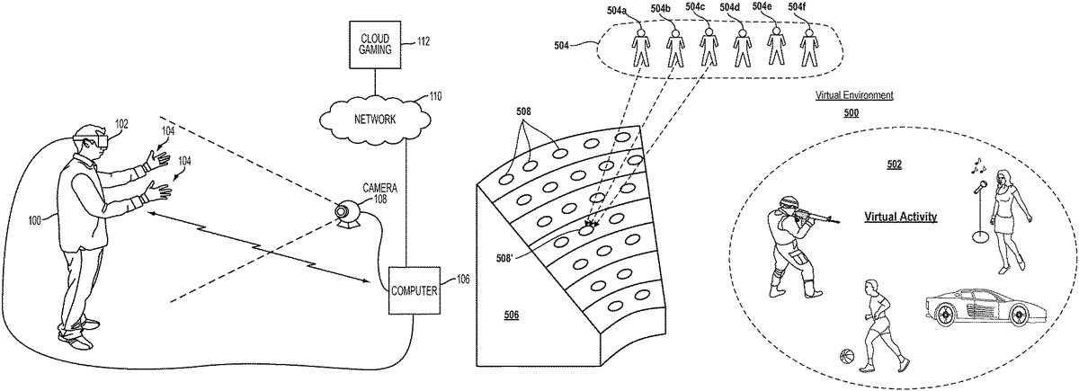
FIG. 5illustrates a virtual environment with locations for spectators, in accordance with implementations of the disclosure. In the illustrated implementation, a VR environment500is shown, in which some activity502or event of interest takes place which users may wish to spectate. For example, the VR environment500may be a three-dimensional (3D) gaming environment in which gameplay of a video game occurs. It will be appreciated that the activity taking place in the VR environment can be any type of virtual activity, including, without limitation, combat (e.g. a first-person shooter game), real-time strategy, racing, sports, dance, theater, musical performance, game show, etc.
To accommodate a number of spectators in the VR environment, there can be a designated viewing area, where a plurality of spectator avatars can be positioned. Strictly speaking, a spectator is a user (human) that spectates the VR environment (e.g. using an HMD). However, the spectator can be represented in the VR environment by an avatar (also referred to as the spectator's avatar), which may be controlled by the spectator. As the spectator's avatar in the VR environment is representative of the spectator and controlled by the spectator, for ease of description in the present disclosure, the spectator and his/her avatar may in some instances be used interchangeably. It will be apparent to those skilled in the art that the (human) spectator is distinct from the spectator's avatar, but the two may nonetheless be referenced in a synonymous manner to simplify the description of the present implementations.
In the illustrated implementation, the designated viewing area is conceptualized as a stadium seating structure506. However, it will be appreciated that in various implementations of the disclosure the designated viewing area can take any form having a plurality of predefined locations at which spectator avatars can be positioned. Merely by way of example, without limitation, the designated viewing area could be one of (or a part of) a hill, field, bleachers, seats, arena, stadium, theater, club, sidewalk, roadside, steps, patio, deck, platform, rooftop, skybox, vehicle (e.g. automobile, train, boat, airplane, helicopter, spacecraft, etc.), or any other type of virtual object which may serve as an area in the VR environment from which spectators may spectate the virtual activity502.
With continued reference toFIG. 5, the stadium seating structure506includes a plurality of locations508(which may be seats in the stadium seating structure) which are predefined for placement of spectator avatars. The spectators504are conceptually shown including spectators504a-f, etc. As the virtual environment500is not subject to real-world physical constraints, it is possible to provide each of the spectators504with the “best seat in the house.” That is, each spectator can spectate from the same preferred location, which in the present instance is the location508′. It will be appreciated that the “best” location for spectating, from among a plurality of possible locations, is predefined and may be determined based on various factors, such as proximity to the activity of interest, height, scope of the view, obstruction of the view (or lack thereof), centeredness relative to the activity of interest, etc.
As noted, each spectator504a-f, etc. spectates from the same location/seat508′, which is the preferred location in the illustrated implementation. Thus, every spectator will experience the same, or substantially the same, viewing perspective in the VR environment500. However, to achieve a sense of being in a crowd, when providing the view to a given spectator from the location508′, then the remaining spectators can be positioned at other locations508around the given spectator in the structure506. For example, for purposes of providing a spectator view of the VR environment to spectator504a, then spectator504a's avatar (and viewpoint) is positioned at location508′, and the other spectators504b-f, etc. are positioned at the other locations508in the structure506. Whereas when providing the spectator view for spectator504b, then spectator504bis positioned at location508′, and the other spectators504a,504c-f, etc. are positioned at the other locations508in the structure506. Thus, the spectator504amay look around from the standpoint of location508′ and see the other spectator avatars surrounding him/her. Likewise, the spectator504bmay also look around from the standpoint of location508′ and see the other spectator avatars surrounding him/her. Thus, all the spectators can be provided with the “best” viewing position, yet also experience the sensation of being in a crowd of spectators. As will be discussed further below, the orientations of the spectators can be adjusted depending on the spectator for whom the view is being provided.
FIG. 6illustrates placement of spectators in a viewing area/region of a VR environment, in accordance with implementations of the disclosure. In the illustrated implementation, a viewing region/area600is provided having nine locations/seats S1-S9. A plurality of spectators U1to U9(conceptually shown at ref.602) are positioned in the locations S1-S9, depending upon which spectator is being provided with the view of the VR environment in which the viewing region600is disposed. In the viewing region600, the location S5is the best location/seat for spectating, and therefore each user will spectate from the location S5. For a given spectator that is placed at the location S5when spectating, then the remaining spectators are placed in the other remaining locations/seats around him/her in the viewing region600.
One way of managing the placement of spectators in the locations of the viewing region600is to define an order of the locations of the viewing region, and an order of the spectators, and shift the order of spectators relative to the order of the locations. Such a setup is illustrated by the seating matrix604, in which each row indicates for a given viewing user (spectator for whom the view of the VR environment is being provided) the assignment of spectators to locations in the viewing region600. Thus, in each row, the viewing user is assigned to location S5, as S5is the best or preferred seat/location. In other words, each spectator will spectate the VR environment from the same location S5.
By way of example, in the illustrated implementation, the arrangement of spectators that is provided when spectator U3is viewing the VR environment is shown. Spectator U3is positioned at location S5, while spectators U4to U7are positioned at locations S6to S9, respectively. Spectators U8and U9are positioned at locations S1and S2, respectively, and spectators U1and U2are positioned at locations S3and S4, respectively. Thus, when spectator U3spectates the VR environment, he/she will be able to see the corresponding avatars of the other spectators positioned as thus indicated. When another spectator spectates the VR environment, he/she will see the other spectators positioned in a different manner in the viewing region600.
FIGS. 7A and 7Billustrate adjustment of spectator avatars in a VR environment based on their controlling spectator's perceived object of interest, in accordance with implementations of the disclosure. As has been discussed above, when multiple spectators are viewing the VR environment, each one can be provided a view from a preferred location, while avatars of other spectators are positioned at other locations in the VR environment. Thus, the locations of the spectator avatars in the VR environment is dependent upon which spectator for whom the view is being provided. Each spectator will see the VR environment from the same location, but will experience other spectators at other locations surrounding him/her.
However, if for a given spectator's view, the other spectators are simply relocated, they may not appear to be looking at the correct object in the VR environment which they are really looking towards. For example,FIG. 7Aillustrates a VR environment700as seen from the perspective of a user U1. In the illustrated implementation, the VR environment as experienced by the user U1is configured such that the user U1is positioned at a preferred location702in front of an object or scene of interest. By way of example only without limitation, in the illustrated implementation, the object of interest is a performer701. The user U1is looking towards the performer701and thus exhibits a view direction indicated by the dashed arrow706.
FIG. 7Billustrates the VR environment700as seen from the perspective of a user U2. In the illustrated implementation, the VR environment as experienced by the user U2is configured such that the user U2is positioned at the preferred location702in front of the object/scene of interest, which is performer701as noted. Additionally, in user U2's view of the VR environment, the user U1has been repositioned at the location704. By repositioning user U1's avatar without adjusting the view direction706that user U1exhibited in his view as described above, then the view direction of user U1's avatar will not appear, in user U2's view, to be looking towards the performer701. Therefore, it is useful to adjust the view direction of the user U1avatar in user U2's view of the VR environment, to view direction712, so that user U1's avatar is looking towards the performer701. It will be appreciated that adjusting the view direction of the avatar may entail adjustment, such as turning or other pose adjustment, of the avatar's head, eyes, torso, legs, entire body, etc.
Likewise, with reference toFIG. 7Aagain, in a similar manner as described above, when providing the view of the VR environment to user U1, the view direction of the user U2's avatar can be adjusted from view direction708to view direction710, so as to be towards the performer701that is the object of interest.
In order to provide proper adjustment of the avatars of other spectators in the VR environment, the system can be configured to determine what object in the VR environment that a given spectator is looking towards. This can be determined based on extrapolating the view direction of the given spectator to an object in the virtual environment, and will be based on the real-world pose of the HMD that the spectator is wearing, as well as the spectator's location in the VR environment. Thus, when a spectator is viewing the VR environment, logic can be configured to determine the spectator's view direction, and based on the spectator's view direction determine an object of interest towards which the view direction is pointing or directed. Then when the spectator's avatar is rendered in another spectator's view of the VR environment, it can be adjusted so as to have a view direction that is towards the object of interest.
FIGS. 8A, 8B, and 8Cillustrate a VR scene in a VR environment as viewed from the perspectives of three different spectators, in accordance with implementations of the disclosure. With reference toFIG. 8A, the VR scene is shown as viewed from the perspective of user/spectator U1, who is positioned at a predefined spectator location802. In the VR scene are a character806and a monster808. Also, avatars of other users/spectators U2and U3are shown, positioned at predefined spectator locations804and800, respectively. The spectator U1has a view direction810that is directed towards the spectator U2's avatar. The spectator U2's avatar has a view direction812towards the monster808. And the spectator U3's avatar has a view direction814towards the character806. It will be appreciated that in some implementations, the spectators are wearing HMDs, and the view directions of the spectators in the VR environment have been determined based on detected real-world poses of the HMDs.
FIG. 8Billustrates the VR scene as viewed from the perspective of spectator U2. As shown, the spectator U2occupies location802, while spectators U1and U3occupy locations800and804, respective. The spectator U2has a view direction818that is towards the monster808; the spectator U1avatar has a view direction816towards spectator U2's location; the spectator U3avatar has a view direction820towards the character806.
FIG. 8Cillustrates the VR scene as viewed from the perspective of spectator U3. As shown, the spectator U3occupies location802, while spectators U2and U3occupy locations800and804, respective. The spectator U3has a view direction824that is towards the character806; the spectator U1avatar has a view direction826towards spectator U2's location; the spectator U2avatar has a view direction822towards the monster808.
As can be seen from the above, by adjusting the view directions of other spectators' avatars when presenting the VR scene to a particular spectator, then the rendering of the other spectators' avatars can be faithful in indicating what objects in the VR environment are currently being viewed by the other spectators.
Though the concepts described herein are described with reference to specific numbers of spectators, it should be appreciated that they may be applied to any number of spectators. Additionally, in some implementations, some spectators can be positioned in proximity to each other based on various factors, such as membership in a social graph (connection or being “friends” on a social network), geographic location, common language, age, gender, interests, gaming history, etc.
FIG. 9conceptually illustrates a plurality of spectators organized into various viewing groups, in accordance with implementations of the disclosure. In the illustrated implementation, a plurality of spectators can be organized into various viewing groups, such as viewing groups902a-e. It will be appreciated that in some implementations, the number of spectators to be included in a given viewing group can vary. For example, viewing group902ais defined to include three spectators; viewing group902bis defined to include four spectators; viewing group902cis configured to include nine spectators; etc. Whereas, in other implementations, a single group size is specified. For purposes of viewing the VR environment, when providing a view of the VR environment for a given spectator, the viewing group to which that spectator is assigned is positioned in the VR environment at a preferred viewing location, such as location906in the viewing region structure904.
A given viewing group defines a spatial arrangement of the spectators that are in the viewing group. That is, when rendered in the VR environment, the spectator avatars of the viewing group will have a particular spatial arrangement that is fixed, in the sense that (unlike some previously described implementations) the spectators' locations relative to each other do not change depending on which spectator's view is being provided. By way of example, viewing group902C as shown defines an arrangement of nine spectator positions within the group as shown; and each spectator of the group would be assigned to one of the nine positions. Thus, spectators of a given viewing group do not spectate from the exact same location in the VR environment, but rather from different locations that are proximate to each other. And within the particular viewing group, the location of one of the spectators is consistent when rendering views of the VR environment for each of the spectators of the group.
However, it will be appreciated that each of the various groups can be positioned at the same, or substantially the same (e.g. if group sizes vary), location in the VR environment (so as to provide every spectator with a view from a preferred viewing location). Thus, spectators from different groups may indeed be positioned at the same location in the VR environment. However, such spectators from different groups would not simultaneously be rendered at the same location when providing a view of the VR environment. For when providing a view of the VR environment to a given spectator, then only the members of the given spectator's viewing group would occupy their particular locations in the VR environment (as defined by the viewing group's arrangement of spectators).
As the spatial location of spectators within a viewing group is fixed (i.e. does not change depending on which spectator of the group is being provided with a view of the VR environment), then the view directions of the spectators in the viewing group do not need to be adjusted when rendering views of the VR environment for the group's spectators. Furthermore, potentially unnatural or odd adjustments in view direction are avoided, and more natural interaction between spectators via their VR avatars is obtained.
When providing a view for a given spectator, beyond the spectator's viewing group, other viewing groups or other spectator avatars can be rendered at other proximate locations that are not occupied my members of the spectator's viewing group. The view directions of such other spectator avatars may be adjusted based on objects of interest towards which their corresponding spectators are looking.
It will be appreciated that spectators900can be organized into viewing groups based on relationships in a social graph. For example, it can be useful to group a given spectator with his/her friends on a social network, or based on any other factor, such as the factors enumerated above regarding positioning of spectators in proximity to each other.
In some implementations, spectators of a given viewing group are permitted to interact with one another. Whereas such spectators are not permitted to interact with other spectators that are not in the given viewing group.
FIG. 10Aillustrates a viewing group1000in a VR environment surrounded by additional viewing groups1002a-h, in accordance with implementations of the disclosure. The viewing group1000is positioned at a preferred viewing location in the VR environment. In some implementations, the additional viewing groups are selected dynamically from a pool of viewing groups. However, in other implementations, the viewing groups are logically arranged in a layout, and the layout of viewing groups is conceptually “shifted” so as to present a specific viewing group at the preferred viewing location in the VR environment (when presenting a view for a spectator in the specific viewing group). The viewing region in the VR environment may accommodate a limited number of spectators or viewing groups, and so a portion of the layout of viewing groups can be fitted so that the specific viewing group is positioned at the preferred viewing location in the VR environment. In some implementations, the layout can be logically configured in a continuous manner, so that every viewing group is bordered on all sides by another viewing group.
FIG. 10Billustrates a viewing group1000in a VR environment surrounded by additional viewing groups of various sizes, in accordance with implementations of the disclosure. As with the configuration ofFIG. 10A, the additional viewing groups can be dynamically selected and positioned in some implementations. Whereas in another implementation, a layout of the viewing groups is determined, and a portion thereof is fitted to the viewing region of the VR environment so as to position a particular viewing group at the preferred position (e.g. when rendering a view for one of the spectators in the particular viewing group).
FIG. 11illustrates an array1100of spectators, in accordance with implementations of the disclosure. The array1100defines a spatial arrangement of the spectators, defining the relative positioning of the spectators when they are rendered (more specifically, when their avatars are rendered) in the VR environment. In accordance with implementations of the disclosure, each of the spectators can spectate from the same preferred location within the VR environment, while also experiencing a sense of being in a crowd. To accomplish this, when providing the view of the VR environment for a particular spectator1102, by way of example, then a portion1104of the array1100that includes spectator1102is selected so that when the spectators included in the portion1104are fitted to a viewing region in the VR environment, maintaining their spatial relationship to each other as defined by the array, then the spectator1102will be positioned at the preferred location.
For example, in the illustrated implementation, the viewing region1114in the VR environment may have viewing locations to accommodate three rows of spectators, with three spectators in a top row, five in a middle row, and three in a bottom row, with a preferred viewing location being the centermost viewing location1116. Thus, portion1104is selected so as to provide for corresponding three spectators in the row above that of spectator1102, five spectators from spectator1102's row (including two each from the left and right of spectator1102), and three spectators from the row below that of spectator1102. Thus, when the spectators from portion1104are respectively positioned in the corresponding viewing locations of the viewing region1114, then the spectator1102will be positioned in the preferred viewing location, with the other spectators surrounding him in accordance with their spatial relationship defined by the array1100. As shown in the array1100, for example, spectators1106,1108,1110, and1112are positioned immediately below, above, to the left, and to the right, respectively, of spectator1102. Accordingly, when the spectator1102is viewing the VR environment, he will experience spectators1106,1108,1110, and1112positioned immediately below, above, to his left, and to his right, respectively.
It will be appreciated that this spatial relationship amongst spectators of the array1100is maintained regardless of which spectator is viewing the VR environment. So for example, in a view of the VR environment provided to spectator1108, then a different portion of the array would be selected (in order to position spectator1108in the preferred viewing location1116), yet the spatial relationship with other spectators would be maintained as it is according to that defined by the array. Thus, in the view provided to spectator1108, spectator1102would be immediately below spectator1108, spectator1110would be below and to the left of spectator1108, and spectator1112would be below and to the right of spectator1108.
The foregoing configuration can be conceptually described in other ways. For example, the viewing region1114defines an arrangement of viewing locations and can be thought of as a selector that can be shifted to different parts of the array1100depending on which spectator for whom a view of the VR environment is being provided; the viewing locations of the viewing region1114will be populated by the spectators falling within the selector according to their predefined positions in the array. Or the array can be shifted relative to the viewing region1114to similar effect.
Additionally, it will be appreciated that the assignment of spectators to specific positions in the array1100can be based on various factors, such as relationship in a social network, or other factors as described above.
Though implementations have generally been described with reference to a single viewing region in a VR environment, it will be appreciated that there can be multiple viewing regions in a VR environment. Furthermore, there may be multiple pools of spectators which may be defined based on factors such as geographic location, language, experience level, etc. The concepts described herein can be applied to multiple viewing regions and multiple pools of spectator.
In some implementations, the spectator viewing regions may be configured to move within the VR environment, for example, to enable spectating of moving action in the VR environment, such as when a player character moves through a video game environment. The effect can be similar to viewing from a moving vehicle. The principles described above can be applied to enable spectators to have the preferred viewing location within the moving viewing region.
With reference toFIG. 12, a diagram illustrating components of a head-mounted display102is shown, in accordance with an embodiment of the disclosure. The head-mounted display102includes a processor1300for executing program instructions. A memory1302is provided for storage purposes, and may include both volatile and non-volatile memory. A display1304is included which provides a visual interface that a user may view. A battery1306is provided as a power source for the head-mounted display102. A motion detection module1308may include any of various kinds of motion sensitive hardware, such as a magnetometer1310, an accelerometer1312, and a gyroscope1314.
An accelerometer is a device for measuring acceleration and gravity induced reaction forces. Single and multiple axis models are available to detect magnitude and direction of the acceleration in different directions. The accelerometer is used to sense inclination, vibration, and shock. In one embodiment, three accelerometers1312are used to provide the direction of gravity, which gives an absolute reference for two angles (world-space pitch and world-space roll).
A magnetometer measures the strength and direction of the magnetic field in the vicinity of the head-mounted display. In one embodiment, three magnetometers1310are used within the head-mounted display, ensuring an absolute reference for the world-space yaw angle. In one embodiment, the magnetometer is designed to span the earth magnetic field, which is ±80 microtesla. Magnetometers are affected by metal, and provide a yaw measurement that is monotonic with actual yaw. The magnetic field may be warped due to metal in the environment, which causes a warp in the yaw measurement. If necessary, this warp can be calibrated using information from other sensors such as the gyroscope or the camera. In one embodiment, accelerometer1312is used together with magnetometer1310to obtain the inclination and azimuth of the head-mounted display102.
In some implementations, the magnetometers of the head-mounted display are configured so as to be read during times when electromagnets in other nearby devices are inactive.
A gyroscope is a device for measuring or maintaining orientation, based on the principles of angular momentum. In one embodiment, three gyroscopes1314provide information about movement across the respective axis (x, y and z) based on inertial sensing. The gyroscopes help in detecting fast rotations. However, the gyroscopes can drift overtime without the existence of an absolute reference. This requires resetting the gyroscopes periodically, which can be done using other available information, such as positional/orientation determination based on visual tracking of an object, accelerometer, magnetometer, etc.
A camera1316is provided for capturing images and image streams of a real environment. More than one camera may be included in the head-mounted display102, including a camera that is rear-facing (directed away from a user when the user is viewing the display of the head-mounted display102), and a camera that is front-facing (directed towards the user when the user is viewing the display of the head-mounted display102). Additionally, a depth camera1318may be included in the head-mounted display102for sensing depth information of objects in a real environment.
The head-mounted display102includes speakers1320for providing audio output. Also, a microphone1322may be included for capturing audio from the real environment, including sounds from the ambient environment, speech made by the user, etc. The head-mounted display102includes tactile feedback module1324for providing tactile feedback to the user. In one embodiment, the tactile feedback module1324is capable of causing movement and/or vibration of the head-mounted display102so as to provide tactile feedback to the user.
LEDs1326are provided as visual indicators of statuses of the head-mounted display102. For example, an LED may indicate battery level, power on, etc. A card reader1328is provided to enable the head-mounted display102to read and write information to and from a memory card. A USB interface1330is included as one example of an interface for enabling connection of peripheral devices, or connection to other devices, such as other portable devices, computers, etc. In various embodiments of the head-mounted display102, any of various kinds of interfaces may be included to enable greater connectivity of the head-mounted display102.
A WiFi module1332is included for enabling connection to the Internet or a local area network via wireless networking technologies. Also, the head-mounted display102includes a Bluetooth module1334for enabling wireless connection to other devices. A communications link1336may also be included for connection to other devices. In one embodiment, the communications link1336utilizes infrared transmission for wireless communication. In other embodiments, the communications link1336may utilize any of various wireless or wired transmission protocols for communication with other devices.
Input buttons/sensors1338are included to provide an input interface for the user. Any of various kinds of input interfaces may be included, such as buttons, touchpad, joystick, trackball, etc. An ultra-sonic communication module1340may be included in head-mounted display102for facilitating communication with other devices via ultra-sonic technologies.
Bio-sensors1342are included to enable detection of physiological data from a user. In one embodiment, the bio-sensors1342include one or more dry electrodes for detecting bio-electric signals of the user through the user's skin.
A video input1344is configured to receive a video signal from a primary processing computer (e.g. main game console) for rendering on the HMD. In some implementations, the video input is an HDMI input.
The foregoing components of head-mounted display102have been described as merely exemplary components that may be included in head-mounted display102. In various embodiments of the disclosure, the head-mounted display102may or may not include some of the various aforementioned components. Embodiments of the head-mounted display102may additionally include other components not presently described, but known in the art, for purposes of facilitating aspects of the present disclosure as herein described.
FIG. 13is a block diagram of a Game System1400, according to various embodiments of the disclosure. Game System1400is configured to provide a video stream to one or more Clients1410via a Network1415. Game System1400typically includes a Video Server System1420and an optional game server1425. Video Server System1420is configured to provide the video stream to the one or more Clients1410with a minimal quality of service. For example, Video Server System1420may receive a game command that changes the state of or a point of view within a video game, and provide Clients1410with an updated video stream reflecting this change in state with minimal lag time. The Video Server System1420may be configured to provide the video stream in a wide variety of alternative video formats, including formats yet to be defined. Further, the video stream may include video frames configured for presentation to a user at a wide variety of frame rates. Typical frame rates are 30 frames per second, 60 frames per second, and 120 frames per second. Although higher or lower frame rates are included in alternative embodiments of the disclosure.
Clients1410, referred to herein individually as1410A,1410B, etc., may include head mounted displays, terminals, personal computers, game consoles, tablet computers, telephones, set top boxes, kiosks, wireless devices, digital pads, stand-alone devices, handheld game playing devices, and/or the like. Typically, Clients1410are configured to receive encoded video streams, decode the video streams, and present the resulting video to a user, e.g., a player of a game. The processes of receiving encoded video streams and/or decoding the video streams typically includes storing individual video frames in a receive buffer of the Client. The video streams may be presented to the user on a display integral to Client1410or on a separate device such as a monitor or television. Clients1410are optionally configured to support more than one game player. For example, a game console may be configured to support two, three, four or more simultaneous players. Each of these players may receive a separate video stream, or a single video stream may include regions of a frame generated specifically for each player, e.g., generated based on each player's point of view. Clients1410are optionally geographically dispersed. The number of clients included in Game System1400may vary widely from one or two to thousands, tens of thousands, or more. As used herein, the term “game player” is used to refer to a person that plays a game and the term “game playing device” is used to refer to a device used to play a game. In some embodiments, the game playing device may refer to a plurality of computing devices that cooperate to deliver a game experience to the user. For example, a game console and an HMD may cooperate with the video server system1420to deliver a game viewed through the HMD. In one embodiment, the game console receives the video stream from the video server system1420, and the game console forwards the video stream, or updates to the video stream, to the HMD for rendering.
Clients1410are configured to receive video streams via Network1415. Network1415may be any type of communication network including, a telephone network, the Internet, wireless networks, powerline networks, local area networks, wide area networks, private networks, and/or the like. In typical embodiments, the video streams are communicated via standard protocols, such as TCP/IP or UDP/IP. Alternatively, the video streams are communicated via proprietary standards.
A typical example of Clients1410is a personal computer comprising a processor, non-volatile memory, a display, decoding logic, network communication capabilities, and input devices. The decoding logic may include hardware, firmware, and/or software stored on a computer readable medium. Systems for decoding (and encoding) video streams are well known in the art and vary depending on the particular encoding scheme used.
Clients1410may, but are not required to, further include systems configured for modifying received video. For example, a Client may be configured to perform further rendering, to overlay one video image on another video image, to crop a video image, and/or the like. For example, Clients1410may be configured to receive various types of video frames, such as I-frames, P-frames and B-frames, and to process these frames into images for display to a user. In some embodiments, a member of Clients1410is configured to perform further rendering, shading, conversion to 3-D, or like operations on the video stream. A member of Clients1410is optionally configured to receive more than one audio or video stream. Input devices of Clients1410may include, for example, a one-hand game controller, a two-hand game controller, a gesture recognition system, a gaze recognition system, a voice recognition system, a keyboard, a joystick, a pointing device, a force feedback device, a motion and/or location sensing device, a mouse, a touch screen, a neural interface, a camera, input devices yet to be developed, and/or the like.
The video stream (and optionally audio stream) received by Clients1410is generated and provided by Video Server System1420. As is described further elsewhere herein, this video stream includes video frames (and the audio stream includes audio frames). The video frames are configured (e.g., they include pixel information in an appropriate data structure) to contribute meaningfully to the images displayed to the user. As used herein, the term “video frames” is used to refer to frames including predominantly information that is configured to contribute to, e.g. to effect, the images shown to the user. Most of the teachings herein with regard to “video frames” can also be applied to “audio frames.”
Clients1410are typically configured to receive inputs from a user. These inputs may include game commands configured to change the state of the video game or otherwise affect game play. The game commands can be received using input devices and/or may be automatically generated by computing instructions executing on Clients1410. The received game commands are communicated from Clients1410via Network1415to Video Server System1420and/or Game Server1425. For example, in some embodiments, the game commands are communicated to Game Server1425via Video Server System1420. In some embodiments, separate copies of the game commands are communicated from Clients1410to Game Server1425and Video Server System1420. The communication of game commands is optionally dependent on the identity of the command. Game commands are optionally communicated from Client1410A through a different route or communication channel that that used to provide audio or video streams to Client1410A.
Game Server1425is optionally operated by a different entity than Video Server System1420. For example, Game Server1425may be operated by the publisher of a multiplayer game. In this example, Video Server System1420is optionally viewed as a client by Game Server1425and optionally configured to appear from the point of view of Game Server1425to be a prior art client executing a prior art game engine. Communication between Video Server System1420and Game Server1425optionally occurs via Network1415. As such, Game Server1425can be a prior art multiplayer game server that sends game state information to multiple clients, one of which is game server system1420. Video Server System1420may be configured to communicate with multiple instances of Game Server1425at the same time. For example, Video Server System1420can be configured to provide a plurality of different video games to different users. Each of these different video games may be supported by a different Game Server1425and/or published by different entities. In some embodiments, several geographically distributed instances of Video Server System1420are configured to provide game video to a plurality of different users. Each of these instances of Video Server System1420may be in communication with the same instance of Game Server1425. Communication between Video Server System1420and one or more Game Server1425optionally occurs via a dedicated communication channel. For example, Video Server System1420may be connected to Game Server1425via a high bandwidth channel that is dedicated to communication between these two systems.
Video Server System1420comprises at least a Video Source1430, an I/O Device1445, a Processor1450, and non-transitory Storage1455. Video Server System1420may include one computing device or be distributed among a plurality of computing devices. These computing devices are optionally connected via a communications system such as a local area network.
Video Source1430is configured to provide a video stream, e.g., streaming video or a series of video frames that form a moving picture. In some embodiments, Video Source1430includes a video game engine and rendering logic. The video game engine is configured to receive game commands from a player and to maintain a copy of the state of the video game based on the received commands. This game state includes the position of objects in a game environment, as well as typically a point of view. The game state may also include properties, images, colors and/or textures of objects. The game state is typically maintained based on game rules, as well as game commands such as move, turn, attack, set focus to, interact, use, and/or the like. Part of the game engine is optionally disposed within Game Server1425. Game Server1425may maintain a copy of the state of the game based on game commands received from multiple players using geographically disperse clients. In these cases, the game state is provided by Game Server1425to Video Source1430, wherein a copy of the game state is stored and rendering is performed. Game Server1425may receive game commands directly from Clients1410via Network1415, and/or may receive game commands via Video Server System1420.
Video Source1430typically includes rendering logic, e.g., hardware, firmware, and/or software stored on a computer readable medium such as Storage1455. This rendering logic is configured to create video frames of the video stream based on the game state. All or part of the rendering logic is optionally disposed within a graphics processing unit (GPU). Rendering logic typically includes processing stages configured for determining the three-dimensional spatial relationships between objects and/or for applying appropriate textures, etc., based on the game state and viewpoint. The rendering logic produces raw video that is then usually encoded prior to communication to Clients1410. For example, the raw video may be encoded according to an Adobe Flash® standard, .wav, H.264, H.263, On2, VP6, VC-1, WMA, Huffyuv, Lagarith, MPG-x. Xvid. FFmpeg, x264, VP6-8, realvideo, mp3, or the like. The encoding process produces a video stream that is optionally packaged for delivery to a decoder on a remote device. The video stream is characterized by a frame size and a frame rate. Typical frame sizes include 800×600, 1280×720 (e.g., 720p), 1024×768, although any other frame sizes may be used. The frame rate is the number of video frames per second. A video stream may include different types of video frames. For example, the H.264 standard includes a “P” frame and a “I” frame. I-frames include information to refresh all macro blocks/pixels on a display device, while P-frames include information to refresh a subset thereof. P-frames are typically smaller in data size than are I-frames. As used herein the term “frame size” is meant to refer to a number of pixels within a frame. The term “frame data size” is used to refer to a number of bytes required to store the frame.
In alternative embodiments Video Source1430includes a video recording device such as a camera. This camera may be used to generate delayed or live video that can be included in the video stream of a computer game. The resulting video stream, optionally includes both rendered images and images recorded using a still or video camera. Video Source1430may also include storage devices configured to store previously recorded video to be included in a video stream. Video Source1430may also include motion or positioning sensing devices configured to detect motion or position of an object, e.g., person, and logic configured to determine a game state or produce video-based on the detected motion and/or position.
Video Source1430is optionally configured to provide overlays configured to be placed on other video. For example, these overlays may include a command interface, log in instructions, messages to a game player, images of other game players, video feeds of other game players (e.g., webcam video). In embodiments of Client1410A including a touch screen interface or a gaze detection interface, the overlay may include a virtual keyboard, joystick, touch pad, and/or the like. In one example of an overlay a player's voice is overlaid on an audio stream. Video Source1430optionally further includes one or more audio sources.
In embodiments wherein Video Server System1420is configured to maintain the game state based on input from more than one player, each player may have a different point of view comprising a position and direction of view. Video Source1430is optionally configured to provide a separate video stream for each player based on their point of view. Further, Video Source1430may be configured to provide a different frame size, frame data size, and/or encoding to each of Client1410. Video Source1430is optionally configured to provide 3-D video.
I/O Device1445is configured for Video Server System1420to send and/or receive information such as video, commands, requests for information, a game state, gaze information, device motion, device location, user motion, client identities, player identities, game commands, security information, audio, and/or the like. I/O Device1445typically includes communication hardware such as a network card or modem. I/O Device1445is configured to communicate with Game Server1425, Network1415, and/or Clients1410.
Processor1450is configured to execute logic, e.g. software, included within the various components of Video Server System1420discussed herein. For example, Processor1450may be programmed with software instructions in order to perform the functions of Video Source1430, Game Server1425, and/or a Client Qualifier1460. Video Server System1420optionally includes more than one instance of Processor1450. Processor1450may also be programmed with software instructions in order to execute commands received by Video Server System1420, or to coordinate the operation of the various elements of Game System1400discussed herein. Processor1450may include one or more hardware device. Processor1450is an electronic processor.
Storage1455includes non-transitory analog and/or digital storage devices. For example, Storage1455may include an analog storage device configured to store video frames. Storage1455may include a computer readable digital storage, e.g. a hard drive, an optical drive, or solid state storage. Storage1415is configured (e.g. by way of an appropriate data structure or file system) to store video frames, artificial frames, a video stream including both video frames and artificial frames, audio frame, an audio stream, and/or the like. Storage1455is optionally distributed among a plurality of devices. In some embodiments, Storage1455is configured to store the software components of Video Source1430discussed elsewhere herein. These components may be stored in a format ready to be provisioned when needed.
Video Server System1420optionally further comprises Client Qualifier1460. Client Qualifier1460is configured for remotely determining the capabilities of a client, such as Clients1410A or1410B. These capabilities can include both the capabilities of Client1410A itself as well as the capabilities of one or more communication channels between Client1410A and Video Server System1420. For example, Client Qualifier1460may be configured to test a communication channel through Network1415.
Client Qualifier1460can determine (e.g., discover) the capabilities of Client1410A manually or automatically. Manual determination includes communicating with a user of Client1410A and asking the user to provide capabilities. For example, in some embodiments, Client Qualifier1460is configured to display images, text, and/or the like within a browser of Client1410A. In one embodiment, Client1410A is an HMD that includes a browser. In another embodiment, client1410A is a game console having a browser, which may be displayed on the HMD. The displayed objects request that the user enter information such as operating system, processor, video decoder type, type of network connection, display resolution, etc. of Client1410A. The information entered by the user is communicated back to Client Qualifier1460.
Automatic determination may occur, for example, by execution of an agent on Client1410A and/or by sending test video to Client1410A. The agent may comprise computing instructions, such as java script, embedded in a web page or installed as an add-on. The agent is optionally provided by Client Qualifier1460. In various embodiments, the agent can find out processing power of Client1410A, decoding and display capabilities of Client1410A, lag time reliability and bandwidth of communication channels between Client1410A and Video Server System1420, a display type of Client1410A, firewalls present on Client1410A, hardware of Client1410A, software executing on Client1410A, registry entries within Client1410A, and/or the like.
Client Qualifier1460includes hardware, firmware, and/or software stored on a computer readable medium. Client Qualifier1460is optionally disposed on a computing device separate from one or more other elements of Video Server System1420. For example, in some embodiments, Client Qualifier1460is configured to determine the characteristics of communication channels between Clients1410and more than one instance of Video Server System1420. In these embodiments the information discovered by Client Qualifier can be used to determine which instance of Video Server System1420is best suited for delivery of streaming video to one of Clients1410.
Embodiments of the present disclosure may be practiced with various computer system configurations including hand-held devices, microprocessor systems, microprocessor-based or programmable consumer electronics, minicomputers, mainframe computers and the like. The disclosure can also be practiced in distributed computing environments where tasks are performed by remote processing devices that are linked through a wire-based or wireless network.
With the above embodiments in mind, it should be understood that the disclosure can employ various computer-implemented operations involving data stored in computer systems. These operations are those requiring physical manipulation of physical quantities. Any of the operations described herein that form part of the disclosure are useful machine operations. The disclosure also relates to a device or an apparatus for performing these operations. The apparatus can be specially constructed for the required purpose, or the apparatus can be a general-purpose computer selectively activated or configured by a computer program stored in the computer. In particular, various general-purpose machines can be used with computer programs written in accordance with the teachings herein, or it may be more convenient to construct a more specialized apparatus to perform the required operations.
The disclosure can also be embodied as computer readable code on a computer readable medium. The computer readable medium is any data storage device that can store data, which can thereafter be read by a computer system. Examples of the computer readable medium include hard drives, network attached storage (NAS), read-only memory, random-access memory, CD-ROMs, CD-Rs, CD-RWs, magnetic tapes and other optical and non-optical data storage devices. The computer readable medium can include computer readable tangible medium distributed over a network-coupled computer system so that the computer readable code is stored and executed in a distributed fashion.
Although the method operations were described in a specific order, it should be understood that other housekeeping operations may be performed in between operations, or operations may be adjusted so that they occur at slightly different times, or may be distributed in a system which allows the occurrence of the processing operations at various intervals associated with the processing, as long as the processing of the overlay operations are performed in the desired way.
Although the foregoing disclosure has been described in some detail for purposes of clarity of understanding, it will be apparent that certain changes and modifications can be practiced within the scope of the appended claims. Accordingly, the present embodiments are to be considered as illustrative and not restrictive, and the disclosure is not to be limited to the details given herein, but may be modified within the scope and equivalents of the present disclosure.
Claims
- A method, comprising: providing a first view of a virtual environment to a first head-mounted display (HMD), the first view having a first view direction towards a virtual object in the virtual environment, the first view being from a first perspective positioned at a first location;simultaneous with the providing the first view, providing a second view of the virtual environment to a second HMD, the second view being from the first perspective positioned at the first location;wherein providing the second view includes rendering in the second view a virtual character associated to the first view, the rendering of the virtual character in the second view being configured to present the virtual character as being positioned at a second location in the virtual environment, the rendering of the virtual character in the second view being further configured to present the virtual character as having a second view direction that is adjusted relative to the first view direction so as to be from a first-person perspective of the virtual character as the virtual character is positioned at the second location, and so as to be towards the virtual object as shown in the second view.
- The method of claim 1 , wherein the second view direction is adjusted relative to the first view direction by turning a head or body of the virtual character towards the virtual object.
- The method of claim 1 , wherein providing the first view of the virtual environment to the first HMD includes processing data identifying an orientation of the first HMD in a first interactive environment in which the first HMD is disposed;wherein the first view direction is substantially determined by the orientation of the first HMD in the first interactive environment.
- The method of claim 3 , wherein providing the second view of the virtual environment to the second HMD includes processing data identifying an orientation of the second HMD in a second interactive environment in which the second HMD is disposed.
- The method of claim 1 , wherein the virtual object towards which the first view direction is directed is identified based on extrapolation of the first view direction from the first location in the virtual environment.
- The method of claim 1 , wherein the second view direction is determined based on relative positioning of the first location, the second location, and the virtual object in the virtual environment.
- The method of claim 1 , wherein the virtual environment is defined for gameplay of a video game, and wherein the first view and second view are spectator views of the gameplay of the video game.
- A method, comprising: providing a first view of a virtual environment to a first display device, the first view having a first view direction towards a virtual object in the virtual environment, the first view being from a first perspective positioned at a first location;simultaneous with the providing the first view, providing a second view of the virtual environment to a second display device, the second view being from the first perspective positioned at the first location;wherein providing the second view includes rendering in the second view a virtual character associated to the first view, the rendering of the virtual character in the second view being configured to present the virtual character as being positioned at a second location in the virtual environment, the rendering of the virtual character in the second view being further configured to present the virtual character as having a second view direction that is adjusted relative to the first view direction so as to be from a first-person perspective of the virtual character as the virtual character is positioned at the second location, and so as to be towards the virtual object as shown in the second view.
- The method of claim 8 , wherein the second view direction is adjusted relative to the first view direction by turning a head or body of the virtual character towards the virtual object.
- The method of claim 8 , wherein providing the first view of the virtual environment to the first display device includes processing data identifying an orientation of the first display device in a first interactive environment in which the first display device is disposed;wherein the first view direction is substantially determined by the orientation of the first display device in the first interactive environment.
- The method of claim 10 , wherein providing the second view of the virtual environment to the second display device includes processing data identifying an orientation of the second display device in a second interactive environment in which the second display device is disposed.
- The method of claim 8 , wherein the virtual object towards which the first view direction is directed is identified based on extrapolation of the first view direction from the first location in the virtual environment.
- The method of claim 8 , wherein the second view direction is determined based on relative positioning of the first location, the second location, and the virtual object in the virtual environment.
- The method of claim 8 , wherein the virtual environment is defined for gameplay of a video game, and wherein the first view and second view are spectator views of the gameplay of the video game.
- A non-transitory computer readable medium having program instructions embodied thereon that, when executed by a computing device, cause said computing device to perform a method comprising the following operations: providing a first view of a virtual environment to a first head-mounted display (HMD), the first view having a first view direction towards a virtual object in the virtual environment, the first view being from a first perspective positioned at a first location;simultaneous with the providing the first view, providing a second view of the virtual environment to a second HMD, the second view being from the first perspective positioned at the first location;wherein providing the second view includes rendering in the second view a virtual character associated to the first view, the rendering of the virtual character in the second view being configured to present the virtual character as being positioned at a second location in the virtual environment, the rendering of the virtual character in the second view being further configured to present the virtual character as having a second view direction that is adjusted relative to the first view direction so as to be from a first-person perspective of the virtual character as the virtual character is positioned at the second location, and so as to be towards the virtual object as shown in the second view.
- The non-transitory computer readable medium of claim 15 , wherein the second view direction is adjusted relative to the first view direction by turning a head or body of the virtual character towards the virtual object.
- The non-transitory computer readable medium of claim 15 , wherein providing the first view of the virtual environment to the first HMD includes processing data identifying an orientation of the first HMD in a first interactive environment in which the first HMD is disposed;wherein the first view direction is substantially determined by the orientation of the first HMD in the first interactive environment.
- The non-transitory computer readable medium of claim 17 , wherein providing the second view of the virtual environment to the second HMD includes processing data identifying an orientation of the second HMD in a second interactive environment in which the second HMD is disposed.
- The non-transitory computer readable medium of claim 15 , wherein the virtual object towards which the first view direction is directed is identified based on extrapolation of the first view direction from the first location in the virtual environment.
- The non-transitory computer readable medium of claim 15 , wherein the second view direction is determined based on relative positioning of the first location, the second location, and the virtual object in the virtual environment.
Disclaimer: Data collected from the USPTO and may be malformed, incomplete, and/or otherwise inaccurate.