U.S. Pat. No. 10,843,068
6DoF Inside-Out Tracking Game Controller
AssigneeXVisio Technology Corp.
Issue DateJanuary 18, 2018
Illustrative Figure
Abstract
Methods and apparatus are provided for 6DoF inside-out tracking game control. In one novel aspect, a multi-processor architecture is used for VI-SLAM. In one embodiment, the apparatus obtains overlapping image frames and sensor inputs of an apparatus, wherein the sensor inputs comprise gyrometer data, accelerometer data and magnetometer data, splits computation work onto a plurality of vector processors to obtain six degree of freedom (6DoF) outputs of the apparatus based on a splitting algorithm, and performs a localization process to generate 6DoF estimations, and a mapping process to generate a cloud of three-dimensional points associated to the descriptors of the map. In one embodiment, the localization process and mapping process are configured to run sequentially. In another embodiment, the localization process and mapping process are configured to run in parallel.
Description
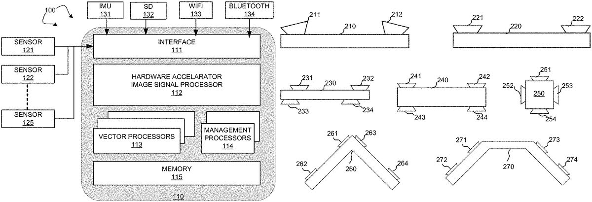
DETAILED DESCRIPTION Reference will now be made in detail to some embodiments of the invention, examples of which are illustrated in the accompanying drawings. FIG. 1illustrates an exemplary block diagram of a 6DoF inside-out tracking game controller100in accordance with embodiments of the current invention. Game controller100is not limited to function as a game controller only. It can be an apparatus used in other scenarios and in combination with other apparatus. In one novel aspect, the 6DoF is produced in real time by game controller100. In one embodiment, game controller100includes a plurality of sensors, such as sensor121,122, and125. In one embodiment, the sensors are cameras. A plurality of cameras for game controller100generate overlapping images. Game controller100also includes an inertial measurement unit (IMU)131, an optional external memory card (SD Card)132Other embodiments and advantages are described in the detailed description below. This summary does not purport to define the invention. The invention is defined by the claims, and one or more wireless interface133, such as a WiFi interface, a Bluetooth interface. An interface module111communicates and controls the sensors, IMU131, SD132, and the wireless interface, such WiFi133and Bluetooth134. A hardware accelerator and image signal processing unit112helps image processing of the sensor inputs. IMU131detects of movements and rotations and magnetic heading of game controller100. In one embodiment, IMU131is an integrated 9-axis sensor for the detection of movements and rotations and magnetic heading. It comprises a triaxial, low-g acceleration sensor, a triaxial angular rate sensor and a triaxial geomagnetic sensor. IMU131senses orientation, angular velocity, and linear acceleration of game controller100. In one embodiment, game controller100processes data of an IMU frame rate of at least 500 Hz. In one embodiment, a plurality of cameras are mounted on the outer case of the game controller to generate overlapping views for the game controller. Using multiple cameras with overlapping ...
DETAILED DESCRIPTION
Reference will now be made in detail to some embodiments of the invention, examples of which are illustrated in the accompanying drawings.
FIG. 1illustrates an exemplary block diagram of a 6DoF inside-out tracking game controller100in accordance with embodiments of the current invention. Game controller100is not limited to function as a game controller only. It can be an apparatus used in other scenarios and in combination with other apparatus. In one novel aspect, the 6DoF is produced in real time by game controller100. In one embodiment, game controller100includes a plurality of sensors, such as sensor121,122, and125. In one embodiment, the sensors are cameras. A plurality of cameras for game controller100generate overlapping images.
Game controller100also includes an inertial measurement unit (IMU)131, an optional external memory card (SD Card)132Other embodiments and advantages are described in the detailed description below. This summary does not purport to define the invention. The invention is defined by the claims, and one or more wireless interface133, such as a WiFi interface, a Bluetooth interface. An interface module111communicates and controls the sensors, IMU131, SD132, and the wireless interface, such WiFi133and Bluetooth134. A hardware accelerator and image signal processing unit112helps image processing of the sensor inputs. IMU131detects of movements and rotations and magnetic heading of game controller100. In one embodiment, IMU131is an integrated 9-axis sensor for the detection of movements and rotations and magnetic heading. It comprises a triaxial, low-g acceleration sensor, a triaxial angular rate sensor and a triaxial geomagnetic sensor. IMU131senses orientation, angular velocity, and linear acceleration of game controller100. In one embodiment, game controller100processes data of an IMU frame rate of at least 500 Hz.
In one embodiment, a plurality of cameras are mounted on the outer case of the game controller to generate overlapping views for the game controller. Using multiple cameras with overlapping view has many advantages compared to monocular solution, such as the scale factor of the 3D motion does not drift, the 3D points seen on the overlapping area can be triangulated without a motion of the device, the matching on the overlapping area is faster and more accurate using the epipolar geometry, the global field of view is wider which increase the accuracy and reduce the jittering.
FIG. 2illustrates exemplary multi-camera configurations in accordance with embodiments of the current invention. The multi-camera configurations are not limited by the examples shown. In general, a plurality of cameras can be used to capture stereo images such that overlapping images are obtained. A game controller210has a straight outer case. Two cameras211and211are mounted at close to the two-ends of the outer case and the lens of the cameras are parallel with the surface of the outer case. A game controller220is similarly configured as game controller210with two cameras mounted at close to the edge of the straight line outer case. In other scenarios, four cameras are used. A game controller230has a straight outer case. Four cameras231,232,233, and234are mounted at close to the edge of the outer case. The cameras that are on the same side but opposite to each other are not inline. Similarly, to game controller230, game controller240also has a straight outer case with four cameras241,242,243, and244mounted at close to the edge of the outer case. The cameras that are on the same side but opposite to each other are inline. A game controller250has a square outer case with four cameras251,252,253, and254. Each of the cameras is mounted on one side of the outer case. A game controller260is a “V” shaped outer case. Four cameras261,262,263, and264are mounted on the outer case of game controller260, with two of each the cameras on each leg of the outer case. In another example, a game controller270has an outer case in the shape of a half hexagon. Game controller270has four cameras with two of each mounted on the two outer legs of the outer case. Other configurations and/or different number of cameras can be configured.
FIG. 3illustrates an exemplary data flow for the real time stereo tracking for the game controller in accordance with embodiments of the current invention. Two processes are used, one localization process312for the real-time tracking, and one mapping process311for the map update. One or more stereo cameras341are used. The obtained images are gather in one frame331, which through interface A is passed to the localization process312. Similarly, IMU unit342talks to accelerometer, gyrometer and magnetometer332, which through interface B is passed to localization process312. The localization procedure generates 6DoF pose, IMU, and feature points322and passes through interface G of mapping and loop closure process311. Mapping and loop closure311receives 6DoF pose and IMU and feature points through interface G. Mapping and loop closure311generates descriptors and 3D points321and sends it to localization312via its own interface F and the localization interface C. In one embodiment, mapping and loop closure311also generates 6DoF pose for the game controller through its interface H.
FIG. 4illustrates an exemplary location system data flow for the real time stereo tracking for the game controller in accordance with embodiments of the current invention. The interfaces A, B, C, D, and E each corresponds to the same interfaces as marked in ourFIG. 3. A feature detection procedure411receives stereo images from interface A and descriptors base451. Features detection411detects features452and passes to match with local map procedure412. Procedure412also receives descriptors and 3D points462from local map461. Procedure461generates data462based on input from interface C, which are the outputs from the mapping procedure. Procedure412generates 2D and 3D points453of the matching result and passes to a compute pose procedure413. The localization procedure also receives IMU inputs from interface B and passes a pose prediction procedure414. Procedure414further receives 6DoF pose465. 6DoF pose465is generated by current pose464based on inputs from interface E. Compute pose procedure454based on input453and454compares the result with a threshold at step421. If step421determines that the number of inliers are greater than the threshold, current pose463is passed to current pose procedure464. If step421determines that the number of inliers are not greater than the threshold, the 6DoF pose and IMU and feature points are passed to the mapping process through interface D.
In one novel aspect, the VI-SLAM algorithm is split to run on a plurality of processors based on a splitting algorithm and the sensor inputs.
FIG. 5Aillustrates exemplary flow diagram of splitting the VI-SLAM onto N vector processors for the localization process based on a splitting algorithm in accordance with embodiments of the current invention. In one embodiment, the localization process is a pipeline implemented as a state machine including a feature extraction procedure510, a matching procedure520, and a 6DoF estimation procedure530.
In one embodiment, the feature detection and extraction procedure510is split to be run on N vector processors following the splitting rule. Step511divides the current frame to be processes into N equals part. Step512assign each frame part to a corresponding vector processor. Each processor processes one part of the frame following a predefine algorithm. First, a corner is determined. For each pixel pidescribed by a 2D coordinate in the image, and an adjustable threshold t, piis determined to be a corner if there exist a set of K contiguous pixels in the neighbor circle, which are all brighter than (pi+t) or all darker than (pi−t). In some embodiment, threshold t is in the range of 5<t<200. In another embodiment, the K is in the range of 5<K<13. In yet another embodiment, the neighbor circle has a radius of three pixels. Subsequently, at the second step, each corner pixel piis classified, using a n×n sub-image centered on pi, to a compressed descriptor. This is done using a base matrix to convert each sub-image to a 16 floats descriptor. The base matrix is computed with a singular value decomposition on a large set of selected features. In one embodiment, the n×n sub-image is 11×11. Let P=(p1, . . . , pn) the list of features points (2D coordinate in the image) detected from the current frame. Let D=(d1, . . . , dn) the list of descriptors associated pair with each feature point with its associated descriptor.
In another embodiment, the matching procedure520is split onto N vector processors. Step521splits the descriptor list into N parts. In one embodiment, the descriptor list is equally split into N part. Step522performs descriptor matching for each descriptor Diby matching Diwith a subset of the map descriptors. The descriptors are split in N equal range. For each vector process i, a matching algorithm applies for Di. The processor i (0<i<N+1) run the matching algorithm on the range Di, The descriptors Diare matched with a subset of the descriptors of the map LocalMap (subset of the map), using the cross-matching method: each match is a pair of descriptor (da, db) such as dais the best candidate for dbamong the descriptors Diof the current frame and dbis the best candidate for daamong the descriptors of the map LocalMap. Some of the descriptors of the map are associated to some 3D points geo-referenced in world (this 3D estimation is performed by the mapping algorithm). So the matching associates each descriptor dide D to a 3D point p3d of the LocalMap. The output of the matching is a list of descriptor pairs associating the features points P to the 3D points of the map: Mi=((p1,p3d1), . . . , (pn,p3dn)).
In yet another embodiment, estimation 6DoF procedure530is split onto N processors. The input of this step is the N lists Mi(from the matching). The 6DoF estimation minimizes, for each pair (pi,p3di) in M, the difference in 2D between the projected of p3diin the current frame and pi. This minimization is performed with the non-linear least square algorithm Levenberg-Marquardt combined with the M-Estimator (robust method) of Geman-McClure. The robust method of Levenberg-Marquard is used on N processors. Once split, each processor i computes the reprojection error of all the elements of Mi:Ei, computes the Jacobian error function of all elements of Mi:Ji. Subsequently, the total number of N Ei in E and the total number of N Ji in J are merged with concatenation. The median of the absolute different of E (MAD) is computed. The estimation of 6DoF is obtained by solving the linear system of (JTJ) X=JTE·MAD, where X is the update of the 6DoF.
FIG. 5Billustrates exemplary flow diagram of splitting the VI-SLAM onto N vector processors for the mapping process based on a splitting algorithm in accordance with embodiments of the current invention. The mapping process takes inputs of features points, descriptors and current pose and generates a cloud of 3D points associated to the descriptors. The mapping process includes a matching procedure560and an optimization procedure570. Matching procedure560is split onto multiple processors. The features points coming from the localization are matched with a subset of features points of the map using the cross matching method. The splitting algorithm involves: splitting the range of features to match in M equal ranges. Each range is processed using a different processor. Each match performed with a descriptor which is not already associated to a 3D point of the map allows the triangulate on of a new 3D point. Optimization procedure570optimizes the pose and 3D points of the map to minimize the reprojection error with the Levenberg-Marquardt algorithm. The optimization may further involve: 3D point culling wherein the 3D points seen only in 2 images are removed because they are not relevant; a key frame culling that removes the key frames (poses of the map) which contain a lot of 3D points in common because they are redundant; the loop-closure procedure detects the multiple instances of the same 3D points in the map and merge them in order to save some memory and to reduce the drift of the 3D reconstruction.
In one novel aspect, using the multi-processor processors architect, the efficiencies of the localization process and the mapping process are greatly improved.
FIG. 6illustrates an exemplary parallel and an exemplary sequential process in the multi-processor configuration in accordance with embodiments of the current invention. Multiple processors, Processor601, Processor602, Processor603, and Processor612. In one embodiment, the localization process, such localization611and localization612are configured to run in serial on all the vector processors. Each localization process is split on all the vector processors. The mapping process, such as mapping process612and mapping process619. The mapping process, such mapping612and mapping619are configured to run on all the vector processors. Each mapping process is split on all the vector processors. In another embodiment, the localization process and the mapping process are run in parallel. A localization process621is configured to occupy processor601to process608all the time. Each localization process uses a subset of the vector processors. The mapping process uses the rest of the vector processors, such as processor609to processor12.
FIG. 7illustrates exemplary diagram of a calibration process in accordance with embodiments of the current invention. The calibration is divided in three consecutive steps. Step701is the intrinsic calibration. The intrinsic calibration estimates the intrinsic parameters using a known pattern, such as a planar checkerboard pattern or a 3D pattern composed of multiple checkerboards with different position and orientation. The intrinsic calibration does not require overlapping area. This can be done before the cameras are mounted. Step702is the extrinsic calibration. The extrinsic calibration estimates of the rotation and translation between each camera; this require to have the intrinsic calibration and to see a known pattern in the overlapping area. This step must be done once all the cameras are mounted. The triangulation of the checkerboard seen at the same time with the cameras give the baseline between the cameras using. Step703is the intrinsic and extrinsic refinement using a motion. Moving the device on the 6DoF following a known and pre-determined motion (on all the translation and orientation axis) recording the frames. Then we use a structure from motion algorithm to estimate the motion and the 3D points frame the recorded frame. During this step, we optimize the intrinsic and extrinsic parameters to refine their values using a motion constraint based on the known and pre-determined motion: the optimization algorithm estimates the set of intrinsic and extrinsic parameters which are required to explain the known and pre-determined motion.
FIG. 8illustrates an exemplary flow chart for the 6DoF inside-out tracking process in accordance with embodiments of the current invention. At step801, the apparatus obtains overlapping image frames and sensor inputs of an apparatus, wherein the sensor inputs comprise gyrometer data, accelerometer data and magnetometer data. At step802, the apparatus splits computation work onto a plurality of vector processors to obtain six degree of freedom (6DoF) outputs of the apparatus based on a splitting algorithm. At step803, the apparatus performs a localization process to generate 6DoF estimations, and a mapping process to generate a cloud of three-dimensional points associated to the descriptors of the map.
Although the present invention has been described in connection with certain specific embodiments for instructional purposes, the present invention is not limited thereto. Accordingly, various modifications, adaptations, and combinations of various features of the described embodiments can be practiced without departing from the scope of the invention as set forth in the claims.
Claims
- An apparatus, comprising: a plurality of cameras mounted on an outer case of the apparatus, wherein the plurality of cameras generates overlapping views to be processed by the apparatus;an inertial measurement unit (IMU) that detects movements, rotations, and magnetic headings of the apparatus;and a multi-processor controller that generates series of six degree of freedom (6DoF) outputs of the apparatus based on sensor inputs of the plurality of the cameras and the IMU, wherein each 6DoF output comprising six dimensions of the apparatus including three dimensions of an orientation in a rotation space and three dimensions translated in a 3D space, wherein the multi-processor controller comprising one or more management processors and a plurality of vector processors, and wherein the one or more management processors splits computation work of the 6DoF outputs onto the plurality of vector processors based on a splitting algorithm and the sensor inputs.
- The apparatus of claim 1 , wherein the IMU comprising one or more triaxial sensors, one or more low-g acceleration sensors, one or more triaxial angular rate sensors and one or more triaxial geomagnetic sensors.
- The apparatus of claim 1 , wherein the IMU is an integrated nine-axis sensor.
- The apparatus of claim 1 , wherein the plurality of vector processors are configured to perform a localization process and a mapping process, and wherein the localization process generates 6DoF estimations, and wherein the mapping process generates a cloud of three-dimensional points associated to the descriptors of the map.
- The apparatus of claim 4 , wherein the localization process involves: detecting and extracting feature points of a current frame;matching feature points to associating 3D points of a map and generating a list of descriptor pairs associating feature points with its associating 3D points of the map;and estimating the 6DoF output of the current apparatus.
- The apparatus of claim 5 , wherein the detecting and extracting involves: dividing a current frame in N equal part;and each of a set of selected vector processors processes a portion of the current frame based on a split-by-corner rule, and wherein the split-by-corner rule determining whether each pixel of is a corner and classifying each pixel determined to a corner to a compressed descriptor by converting each sub-image centered by the pixel to a 16-float descriptor using a base matrix.
- The apparatus of claim 4 , wherein the mapping process involves: matching feature points from the localization process with a subset of feature points map using a cross matching algorithm;and optimizing poses and 3D points of a map.
- The apparatus of claim 4 , wherein the localization process and mapping process are configured to run sequentially, wherein the localization process is split over all of the vector processors and the mapping process is split over all the vector processors.
- The apparatus of claim 4 , wherein the localization process and mapping process are configured to run in parallel, wherein the localization process is split over a first subset of the vector processors and the mapping process is split over the rest subset of the vector processors.
- The apparatus of claim 1 , wherein the 6DoF outputs is in one format selecting from an output format group comprising: six floating point values with three for the translated 3D space and three for the rotation space, twelve floating point values with three for the translated 3D space and nine for the rotation space, six fix point values with three for the translated 3D space and three for the rotation space, and twelve fix point values with three for the translated 3D space and nine for the rotation space.
- A method, comprising: obtaining overlapping image frames and sensor inputs of an apparatus, wherein the sensor inputs comprise gyrometer data, accelerometer data and magnetometer data;splitting computation work onto a plurality of vector processors to obtain six degree of freedom (6DoF) outputs of the apparatus based on a splitting algorithm;and performing a localization process to generate 6DoF estimations, and a mapping process to generate a cloud of three-dimensional points associated to the descriptors of the map.
- The method of claim 11 , wherein the splitting algorithm involves: dividing a current frame in N equal part;and each of a set of selected vector processors processes a portion of the current frame based on a split-by-corner rule, and wherein the split-by-corner rule determining whether each pixel of is a corner and classifying each pixel determined to a corner to a compressed descriptor by converting each sub-image centered by the pixel to a 16-float descriptor using a base matrix.
- The method of claim 11 , wherein the localization process and mapping process are configured to run sequentially, wherein the localization process is split over all of the vector processors and the mapping process is split over all the vector processors.
- The method of claim 11 , wherein the localization process and mapping process are configured to run in parallel, wherein the localization process is split over a first subset of the vector processors and the mapping process is split over the rest subset of the vector processors.
- The method of claim 11 , wherein the 6DoF outputs is in one format selecting from an output format group comprising: six floating point values with three for the translated 3D space and three for the rotation space, twelve floating point values with three for the translated 3D space and nine for the rotation space, six fix point values with three for the translated 3D space and three for the rotation space, and twelve fix point values with three for the translated 3D space and nine for the rotation space.
Disclaimer: Data collected from the USPTO and may be malformed, incomplete, and/or otherwise inaccurate.