U.S. Pat. No. 10,821,354
DEVICE FOR CONTROLLING A VIDEO GAME
AssigneeF.SMIT HOLDING B.V.
Issue DateOctober 27, 2016
Illustrative Figure
Abstract
The invention relates to a device for controlling a video game, comprising a seat, at least one operating member connected to the video game, means for displacing the seat and the at least one operating member relative to each other and means for fixing the seat and the at least one operating member in a number of different positions relative to each other. According to an aspect of the invention, the fixation means are form-fitting. The fixatin means can here comprise a gear rack and a toothed block for placing into engagement therewith. The toothed block and the gear rack can be movable toward and away from each other in the direction of their toothing or be pivotable relative to each other parrallel to the toothing. According to another aspect of the invention, the displacing means comprise a pair of mutually parallel rails and a pair of bearing blocks slidable therealong. Each rail can have a substantially round, optionally solid cross-section and each bearing block can have a substantially round opening through which the corresponding rail protrudes.
Description
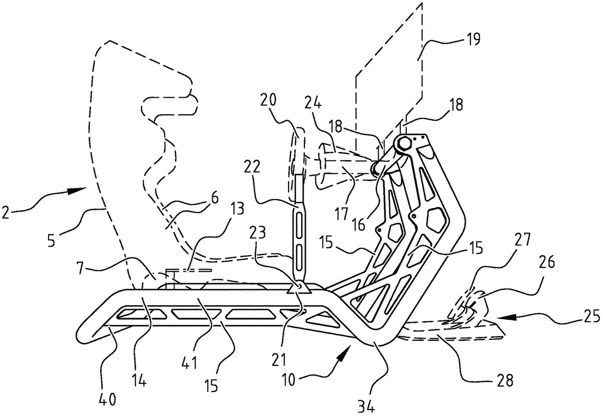
A device1for controlling a video game comprises a seat2and a number of control members3connected thereto. Control device1further has means33for displacing seat2and operating members3relative to each other and means32for fixing seat2and operating members3in a number of different positions relative to each other. Seat2has a seat part4, a backrest5and wings6and is shaped in the manner of a seat in a rally car. Attached to the underside of wings6are shells7which support a part of displacing means33. Displacing means33comprise according to the invention a pair of mutually parallel rails8and a number of bearing blocks11slidable therealong. In the shown embodiment rails8take a solid form and have a round section, while the bearing blocks each have a round opening with which they are arranged close-fittingly round the rail. In the shown embodiment seat2is placed between rails8, thereby achieving a maximum track width and optimum stability. In this embodiment rails are connected to control members3via a frame10to be discussed below, while bearing blocks11are connected via the shells to seat2. Seat2is thus displaceable here relative to operating members3. Each rail8is attached by means of two ears9to a longitudinal girder of frame10. In the shown embodiment frame10is substantially rectangular in top view and has two longitudinal girders41extending on either side of seat2, a transverse girder40behind backrest5of the seat and an elevated transverse girder16at a distance in front of seat2. Frame10takes a very robust form so as to impart thereto an appearance suited to rally racing. Frame10is constructed from tubes which are bent or folded locally in order to obtain the desired shape of frame10. Lattices15are incorporated in the bent or folded parts for strengthening purposes. The rear transverse girder40forms one of the lowest points of frame10and supports on a ground surface. From here the longitudinal girders41are in the first instance bent upward so that they extend roughly at the ...
A device1for controlling a video game comprises a seat2and a number of control members3connected thereto. Control device1further has means33for displacing seat2and operating members3relative to each other and means32for fixing seat2and operating members3in a number of different positions relative to each other. Seat2has a seat part4, a backrest5and wings6and is shaped in the manner of a seat in a rally car. Attached to the underside of wings6are shells7which support a part of displacing means33.
Displacing means33comprise according to the invention a pair of mutually parallel rails8and a number of bearing blocks11slidable therealong. In the shown embodiment rails8take a solid form and have a round section, while the bearing blocks each have a round opening with which they are arranged close-fittingly round the rail. In the shown embodiment seat2is placed between rails8, thereby achieving a maximum track width and optimum stability. In this embodiment rails are connected to control members3via a frame10to be discussed below, while bearing blocks11are connected via the shells to seat2. Seat2is thus displaceable here relative to operating members3.
Each rail8is attached by means of two ears9to a longitudinal girder of frame10. In the shown embodiment frame10is substantially rectangular in top view and has two longitudinal girders41extending on either side of seat2, a transverse girder40behind backrest5of the seat and an elevated transverse girder16at a distance in front of seat2. Frame10takes a very robust form so as to impart thereto an appearance suited to rally racing. Frame10is constructed from tubes which are bent or folded locally in order to obtain the desired shape of frame10. Lattices15are incorporated in the bent or folded parts for strengthening purposes. The rear transverse girder40forms one of the lowest points of frame10and supports on a ground surface. From here the longitudinal girders41are in the first instance bent upward so that they extend roughly at the height of seat surface4of seat2. On the front side the longitudinal girders41are bent downward again whereby they define a front support point34which rests on the ground surface. From this point34the longitudinal girders41are bent upward again so that their outer ends are situated at a height where some of operating members3, in this example steering wheel20, are optimally placed. Longitudinal girders41and rear transverse girder40are formed as one whole14in the shown embodiment. This integral tubular construction14can otherwise be constructed from a number of tube segments welded to each other, or can be formed by a single tube with multiple bends. The front elevated transverse girder16is connected by means of bolts to the U-shaped remainder of frame10.
The elevated transverse girder16carries one of the control members3, in the shown embodiment as stated steering wheel20. Mounted for this purpose on transverse girder16are two arms17which are directed toward seat2and between which a housing24carrying steering wheel20is suspended. In the shown embodiment a screen19, which forms part of the video game, is also mounted by means of two spacers18on the elevated transverse girder16. Steering wheel20and screen19are pivotable as one unit in the shown embodiment. The elevated transverse girder16can for this purpose itself be mounted pivotally between the ends of longitudinal girders41, or it can function as shaft on which a sleeve with spacers17,18thereon is pivotable. Because of the combined pivoting of screen19and steering wheel20the position of screen19will automatically follow the position of steering wheel20, which will be set to the desired height by a user. In order to fix steering wheel20and screen19in the desired position there is arranged on the pivotable part a gear rim30into which engages a cam31arranged on the fixed frame. This cam31can for instance be held in engagement with gear rim30under spring tension and be released by means of a handle (not shown here). Spacers18which carry screen19can, just as arms17, otherwise take a somewhat curved form, whereby screen19is situated in front of transverse girder16and thereby holds steering wheel unit20,24in balance.
In addition to steering wheel20and screen19, frame10also carries a gear lever22which is mounted pivotally on a shaft23between two flanges21welded to the frame tube. Just as steering wheel20, this gear lever22is connected in controlling manner to the video game. Finally, the operating members can further also comprise a set of pedals25consisting of an accelerator pedal26and a brake pedal27, which are each mounted movably in a mounting plate28. The set of pedals25can be attached to frame10or can be attached to the ground surface in fixed position relative to the frame. Frame10and pedal set25can for instance be mounted together on a base plate.
According to another aspect of the invention, fixation means32are form-fitting. In the shown embodiment these fixation means32comprise a gear rack12and a toothed block engaging therein (not shown in this embodiment). Gear rack12is attached by means of ear9, to which rail8is also attached, and a second ear29to a longitudinal girder of frame10. Gear rack12is thus in this way connected via frame10to operating members3. The toothed block is connected in this embodiment to seat2. It is held in engagement with gear rack12by means of a spring (not shown) and can be released from gear rack12by means of a lever13mounted pivotally on the seat frame. When the toothed block is released from gear rack12, seat2can be shifted over rails8, whereby an optimal position of seat2can be set relative to operating members3.
In another embodiment of control device101according to the invention, which is particularly suitable for simulating a racing car, for instance a Formula One car, it is not the seat102which is adjustable relative to operating members103but it is the seat102which forms the reference, and it is the operating members103which are adjustable. In this embodiment seat102, which once again consists of a seat surface104, a backrest105and wings106, is mounted on a frame110of folded plate. Attached to this frame are two rails108which extend forward from seat102. These rails108have a substantially Ω-shaped section with a constriction and a substantially round part thereabove. Slidable over this round part of rails108are bearing blocks111which are attached to sub-frames133and134. Arranged on sub-frame133are legs117which carry a module124on which steering wheel120is mounted. Screen119is also mounted on module124. Sub-frame134has an elevated part130on which pedal set125is mounted. This pedal set in turn comprises a footplate128and accelerator and brake pedals126,127mounted movably thereon. Because pedal set125is mounted on an elevated part135and because the seat102is tilted quite far backwards, this embodiment of control device101makes possible a reclining driving position typical for Formula One cars. Fixation means132in this embodiment once again comprise a gear rack112which in this case is connected to seat102. Fixation means132further comprise two toothed blocks136which are attached to sub-frames133,134. Sub-frames133,134, and thereby steering wheel120and pedal set125, can in this way be adjusted independently of each other relative to seat102. In contrast to the first embodiment, where the toothed block and gear rack12are movable toward and away from each other in the direction of the toothing, in this embodiment the toothed block136and gear rack112are pivotable parallel to the toothing relative to each other. Gear rack112is thus in practice mounted pivotally in pivot bearings129on the two ends thereof. One of these pivot bearings129is mounted on frame110while the other pivot bearing129is mounted on a ground surface. Frame110, rails108and the front pivot bearing129will in practice all be mounted on a shared base plate. Gear rack112has a chamfered side138adjacently of toothing137. By pivoting the gear rack through 45 degrees the toothing137is thus moved out of reach of toothed blocks136and the chamfered side138faces toward toothed blocks136instead. Because this chamfered side protrudes less far outside the pivot axis139of gear rack112, toothed blocks136run clear of this chamfered side138. In this position of the gear rack the sub-frames133,134can thus be slid along rails108until steering wheel120and pedal set125take up an optimal position relative to seat102. A handle (not shown here) is attached to gear rack112for the purpose of pivoting gear rack112. Gear rack112is biased by a spring (not shown here) to the position in which toothing137is in engagement with toothed blocks136, and operating members103are thus fixed relative to seat102.
The invention thus provides a control device for use with a video game with which the operating members and the seat are displaceable in stable and properly guided manner relative to each other so as to thus set an optimal relative position. The seat and the operating members are moreover locked in highly reliable manner relative to each other in the set position by the form-fitting fixation means.
Although the invention has been elucidated above on the basis of two embodiments, it will be apparent that it is not limited thereto but can be varied in many ways. More than two rails could for instance be used for the displacement, while the rails could also have a different cross-sectional form. Bearings other than shown here could also be used. Other form-fitting fixation mechanisms could also be used instead of a toothing, such as for instance holes and a movable pin. Finally, operating members other than the shown steering wheel and the pedal set could also be used. If the video game were to involve for instance the control of an aircraft, the control members could comprise a control column or joystick and a throttle.
The scope of the invention is therefore defined solely by the following claims.
Claims
- A device for controlling a video game, comprising: a seat, at least one operating member connected to the video game, a mechanism for displacing the seat and the at least one operating member relative to each other, and a manually operable mechanism for fixing the seat and the at least one operating member in a number of different positions relative to each other, wherein the displacing mechanism comprises first and second rails and first and second bearing blocks slidable therealong, said first bearing block being slidable along said first rail and the second bearing block being slidable along said second rail, wherein the first and second rails are connected to the at least one operating member and the first and second bearing blocks are connected to the seat, wherein the first and second rails are mounted in a rigid frame which carries the at least one operating member, said rigid frame being rectangular with two longitudinal girders extending on either side adjacently of the seat, a rear transverse girder behind a backrest of the seat and an elevated transverse girder at a fixed distance in front of the rear transverse girder, and wherein each rail has a round section and each bearing block has a round opening through which the corresponding rail protrudes.
- The control device as claimed in claim 1 , wherein each rail has a solid cross-section.
- The control device as claimed in claim 1 , wherein the first and second rails have a spacing therebetween corresponding to a width of the seat.
- The control device as claimed in claim 1 , wherein the longitudinal girders and the transverse girders are each tubular.
- The control device as claimed in claim 4 , wherein the longitudinal girders are bent locally and a lattice is incorporated in the, or each, bent part.
- The control device as claimed in claim 1 , wherein the longitudinal girders and the rear transverse girder are formed integrally.
- The control device as claimed in claim 1 , wherein the elevated transverse girder carries a screen which shows the video game.
- The control device as claimed in claim 1 , wherein the at least one operating member comprises a gear lever connected pivotally to the frame.
- The control device as claimed in claim 1 , wherein the at least one operating member comprises a set of pedals.
- The control device as claimed in claim 1 , wherein the at least one operating member comprises a steering wheel.
- The control device as claimed in claim 1 , wherein the screen and the steering wheel are connected for combined pivoting to the elevated transverse girder.
- The control device as claimed in claim 11 , wherein the screen and the steering wheel are fixable in a plurality of pivoted positions relative to the frame by means of a gear rim and cam engaging therein.
- The control device as claimed in claim 1 , wherein the first and second rails are parallel.
- A device for controlling a video game, comprising: a seat, at least one operating member connected to the video game, a mechanism for displacing the seat and the at least one operating member relative to each other, and a manually operable mechanism for fixing the seat and the at least one operating member in a number of different positions relative to each other, wherein the displacing mechanism comprises first and second rails and first and second bearing blocks slidable therealong, said first bearing block being slidable along said first rail and the second bearing block being slidable along said second rail, wherein the first and second rails are attached to a frame on which the seat is fixedly mounted and the first and second bearing blocks are connected to the at least one operating member.
- The control device as claimed in claim 14 , wherein each rail has a solid cross-section.
- The control device as claimed in claim 14 , wherein the at least one operating member comprises a set of pedals.
- The control device as claimed in claim 14 , wherein the at least one operating member comprises a steering wheel.
- The control device as claimed in claim 14 , wherein the first and second rails are parallel.
- The control device as claimed in claim 14 , wherein the at least one operating member comprises a set of pedals and a steering wheel, wherein the set of pedals is arranged on a first subframe to which a first set of said first and second bearing blocks is attached, and wherein the steering wheel is arranged on a second subframe to which a second set of said first and second bearing blocks is attached.
Disclaimer: Data collected from the USPTO and may be malformed, incomplete, and/or otherwise inaccurate.