U.S. Pat. No. 10,802,279
DISPLAY SYSTEM, DISPLAY METHOD, AND COMPUTER APPARATUS FOR DISPLAYING ADDITIONAL INFORMATION OF A GAME CHARACTER BASED ON LINE OF SIGHT
AssigneeSQUARE ENIX CO., LTD.; GREE, INC.
Issue DateSeptember 7, 2017
Illustrative Figure
Abstract
A display system including a display device which is used by being mounted on the head of a player, comprising: a virtual camera specifier that specifies a visual axis and/or a position of a virtual camera in a virtual space, according to a direction and/or a position of the display device; and a displayer that displays an object present in the virtual space, on the display device, according to the visual axis and/or the position of the virtual camera, wherein in a case where there is an object on the visual axis specified by the virtual camera specifier, the displayer additionally displays information associated with the object.
Description
DESCRIPTION OF EMBODIMENTS Hereinafter, embodiments of the invention will be described with reference to the accompanying drawings. Hereinafter, description relating to effects shows an aspect of the effects of the embodiments of the invention, and does not limit the effects. Further, the order of respective processes that form a flowchart described below may be changed in a range without contradicting or creating discord with the processing contents thereof. An overview of embodiments of the present invention will be described.FIGS. 1A and 1Bare block diagrams showing a configuration of a system corresponding to at least one of the embodiments of the present invention. FIG. 1Ais a diagram showing one example relating to the configuration of the system. The system includes a display device1equipped with a sensor, an irradiation device2that irradiates a light beam, a computer device3that generates or processes an image to be displayed on the display device1, and a controller4equipped with a sensor. The display device1is preferably a goggle-type display device to be mounted on the head so as to cover the field of view. The display may be a transmissive display having a high transmittance or a non-transmissive display having a low transmittance. In addition, the display device1can specify the user's posture by using a plurality of mounted sensors. The configuration of the display device1will be described later. The irradiation device2is a device that irradiates a laser beam in a wide range. If the periphery of the irradiation device2is irradiated with a laser beam, the laser beam is sensed by optical sensors, which are mounted on the display device1and the controller4, and the positions of the display device1and the controller4are specified. This position specifying method is called “Lighthouse method”. In order to specify the position more accurately, it is preferable that at least two irradiation devices2are provided with a ...
DESCRIPTION OF EMBODIMENTS
Hereinafter, embodiments of the invention will be described with reference to the accompanying drawings. Hereinafter, description relating to effects shows an aspect of the effects of the embodiments of the invention, and does not limit the effects. Further, the order of respective processes that form a flowchart described below may be changed in a range without contradicting or creating discord with the processing contents thereof.
An overview of embodiments of the present invention will be described.FIGS. 1A and 1Bare block diagrams showing a configuration of a system corresponding to at least one of the embodiments of the present invention.
FIG. 1Ais a diagram showing one example relating to the configuration of the system. The system includes a display device1equipped with a sensor, an irradiation device2that irradiates a light beam, a computer device3that generates or processes an image to be displayed on the display device1, and a controller4equipped with a sensor.
The display device1is preferably a goggle-type display device to be mounted on the head so as to cover the field of view. The display may be a transmissive display having a high transmittance or a non-transmissive display having a low transmittance. In addition, the display device1can specify the user's posture by using a plurality of mounted sensors. The configuration of the display device1will be described later.
The irradiation device2is a device that irradiates a laser beam in a wide range. If the periphery of the irradiation device2is irradiated with a laser beam, the laser beam is sensed by optical sensors, which are mounted on the display device1and the controller4, and the positions of the display device1and the controller4are specified. This position specifying method is called “Lighthouse method”. In order to specify the position more accurately, it is preferable that at least two irradiation devices2are provided with a predetermined interval.
The computer device3can be connected to the display device1and the controller4by communication. Communication may be performed in a wired or wireless manner. The computer device3may be a device independent from the display device1, or may be an integrated device incorporated in the display device1.
The controller4is an input device that includes a button and a trigger, and receives an input by a user's operation. In addition, the controller4is equipped with an optical sensor which is able to sense the laser beam irradiated from the irradiation device2. Furthermore, the controller4is equipped with a touch sensor which is able to receive an input by a user's touch. The controller4is used in pairs by being held with the left and right hands, but only one of them may be used.
FIG. 1Bis a diagram showing one example relating to the configuration of a system different from the system shown inFIG. 1A. The system shown inFIG. 1Bincludes a display device51having a light emitting unit as a light source, an imaging device52that captures an image of light emitted from the light emitting units which are light sources of the display device51and a controller54, a computer device53that generates or processes an image to be displayed on the display device51, and the controller54having a light emitting unit as a light source.
The display device51is preferably a goggle-type display device to be mounted on the head so as to cover the field of view, similar to the display device1. The display may be a transmissive display having a high transmittance or a non-transmissive display having a low transmittance.
The imaging device52is a device that specifies the positions of the display device51and the controller54by capturing an image of light emitted from the light emitting units which are light sources of the display device51and the controller54.
The computer device53can be connected to the display device51and the controller54by communication. Communication may be performed in a wired or wireless manner.
The controller54is an input device that has a button and receives an input by a user's operation. The controller54also has a light emitting unit which is a light source, and the imaging device52captures an image of light emitted from the controller54to specify the position of the controller54. The controller is to be held with the hand, and it is preferable to use the controller as a pair, but one controller may be used.
In the following description, in the embodiment of the present invention, it is assumed that the positions of the display device1and the controller4are specified by the system shown inFIG. 1A. However, the present invention is not limited to the system. For example, it may be the system shown inFIG. 1Bor a system in which the display device is mounted on a body part other than the head, and the positions of the display device1and the controller4are specified.
The image displayed on the display device1is an image generated or processed by the computer device3, based on a value measured by the sensor mounted on the display device1and a user's input operation to the controller4.
Here, the configuration of the display device1will be described.FIG. 2is a block diagram showing a configuration of a display device corresponding to at least one of the embodiments of the present invention. The display device1includes a control unit11, a Random Access Memory (RAM)12, a storage13, an imaging unit14, a graphics processor15, a display unit16, a sensor unit18, a communication interface19, an interface unit20, and a lens21, and these components are connected to each other by an internal bus.
The control unit11is configured to include a Central Processing Unit (CPU) and a Read Only Memory (ROM). The control unit11executes a program stored in the storage13so as to control the display device1. The RAM12is a work area of the control unit11. The storage13is a storage area for storing programs and data.
The control unit11performs processing by reading programs and data from the RAM12and the storage13. The control unit11processes the program and data which are loaded in the RAM12, thereby output a drawing command to the graphics processor15. Further, the control unit11performs processes based on various values measured by the sensor unit18, or transmits data to the computer device3through the interface unit20.
The imaging unit14outputs an image captured through the lens21to the graphics processor15. In a case where the display device1is mounted on the head and the field of view is covered, information on the outside of the device cannot be checked. Therefore, by displaying information captured by the imaging unit14on a display screen17of the display unit16, which will be described later, the user can recognize the real space and thus the safety can be secured.
The graphics processor15executes drawing of one image in the unit of frames. One frame time for the image is, for example, 1/30 seconds. The graphics processor15has a function of receiving a part of a calculation process relating to the drawing performed only by the controller to disperse a load of the entire system.
The display unit16has the display screen17, and is provided inside the goggle of the display device1covering the user's field of view. For example, an organic EL or an inorganic EL is used as the display screen17, but the present invention is not limited to these.
The sensor unit18includes at least a proximity sensor18a, an infrared sensor18b, a gyrosensor18c, and an acceleration sensor18d. The proximity sensor18ais provided in the goggle portion of the display device1, and is used for determining the presence or absence of contact with the user's face. A plurality of infrared sensors18bare provided in the display device1, and are used to specify the position of the display device1by detecting light beams irradiated from the irradiation device2. The gyrosensor18cand the acceleration sensor18dare used for specifying the user's posture.
Here, a method of specifying a user's posture will be described with reference to the drawings.FIG. 3is a diagram showing a Cartesian coordinate system for specifying the user's posture in a case where the display device is mounted on the head, corresponding to at least one of the embodiments of the present invention.
As shown inFIG. 3, the XYZ-coordinates are defined around the head of the user wearing the display device1. A vertical direction in which the user stands upright is defined as a Y-axis (yaw angle), a direction which is orthogonal to the Y-axis and connects the center of the display screen17of the display device1and the head of the user is defined as a Z-axis (roll angle), and a direction orthogonal to the Y axis and the Z-axis is defined as an X-axis (pitch angle). The gyrosensor18cdetects the angle (inclination) around each axis, and the acceleration sensor18ddetects the movement of the display device1. The image to be displayed on the display screen17is changed according to the detected angle and the detected movement. The display device1can specify the user's posture, using values measured by a plurality of sensors (hereinafter referred to as posture information).
Subsequently, the communication interface19can be connected to a communication network5in a wireless or wired manner, and may receive data via the communication network5. The data received via the communication interface19is loaded into the RAM12, and is subjected to calculation processing by the control unit11.
The interface unit20is mainly connected to the computer device3, and can receive data such as images processed or generated by the computer device3. Further, it is also possible to transmit measured values of various sensors acquired by the sensor unit18to the computer device3.
Subsequently, the computer device3will be described.FIG. 4is a block diagram showing a configuration of a computer device corresponding to at least one of the embodiments of the present invention. The computer device3includes a control unit31, a RAM32, a storage33, a sound processor34, a graphics processor35, a DVD/CD-ROM drive36, a communication interface37, an interface unit38, and a frame memory39, and these components are connected to each other by an internal bus.
The control unit31is configured to include a CPU and a ROM. The control unit31executes a program stored in the storage33so as to control the computer device3. The RAM32is a work area of the control unit31. The storage33is a storage area for storing programs and data.
The control unit31performs processing by reading programs and data from the RAM32. The control unit31processes the program and data loaded in the RAM32to output a drawing command to the graphics processor35.
The sound processor34is connected to a sound output device40. When the control unit31outputs a sound output instruction to the sound processor34, the sound processor34outputs a sound signal to the sound output device40. The sound output device40is, for example, a headphone, and the user may mount it on the head together with the display device1, or the speaker may be incorporated in the display device1.
The graphics processor35executes drawing of one image in the unit of frames. One frame time for the image is, for example, 1/90th second. The graphics processor35has a function of receiving a part of a calculation process relating to the drawing performed only by the controller to disperse a load of the entire system. Since the graphics processor35of the computer device3generates an image to be displayed on the display screen17, based on the position information and the posture information of the display device1and the position information of the controller4, it requires higher performance than the graphics processor15included in the display device1.
The DVD/CD-ROM drive36reads data from a disc41, loads the data into the RAM32, and the control unit31performs a calculation process. The type of the disc41is not limited to the DVD or the CD, but may be a Blu-ray (registered trademark) disc or other standards.
The communication interface37can be connected to the communication network5in a wireless or wired manner, and may receive data via the communication network5. The data received via the communication interface37is loaded into the RAM32in the same manner as the data read from the disc41, and is subjected to calculation processing by the control unit31.
The interface unit38is mainly connected to the display device1, and can transmit data such as images processed or generated by the computer device3.
In the above description, the display device1and the computer device3are described as separate devices, but all of the processes of the computer device3may be performed by the display device1. In that case, the computer device3is not required, and the controller4is connected to the display device1by communication.
Subsequently, the program execution process according to the embodiment of the present invention will be described. An example of the embodiment of the present invention is a game in which a player performs virtual battle with an enemy character in a virtual world, and if cards to be owned by a player is selected, the action of a player character is determined, and the virtual battle progresses. The player may operate a single player character, or a team composed of a plurality of player characters. The card owned by the player is stored in the player account directly or in association with the player character.
FIG. 5is an example of a game execution screen, corresponding to at least one of the embodiments of the present invention. On the display screen17, the status of the virtual battle is displayed, and at least an enemy character101, system instruction information102, a card group103usable by a player character and imitating a plurality of characters, which is an option to be selected by the player, and a hand portion104of the player in the virtual world are displayed. Although not shown, the player character has a value representing the physical strength of the player character (hereinafter referred to as a physical strength value), and when the physical strength value disappears, the player character becomes a battle impossible state and the game ends. In addition, when the life force (not shown) of the enemy character101disappears, the enemy character becomes a battle impossible state, it is determined that the player has won, and the game ends.
By operating the controller4, the player instructs the player character in the virtual world to take action. The operation of the controller4is, for example, an operation of changing the position and inclination of the controller4, or a pressing or touching operation with respect to a button or the like of the controller4. By using change information on the position and inclination of the controller4as input information, the player can perform an intuitive operation and can concentrate more on the game.
As a premise of the embodiment of the present invention, when the program is executed, the control unit31of the computer device3causes the graphics processor35to output the virtual space defined by the program. Further, the position of the player wearing the display device1on the head, and the position of the controller4are specified based on the position and direction where the light beam irradiated from the irradiation device2is received. Furthermore, the posture of the display device1is specified, based on the measured values of various sensors of the sensor unit18of the display device1.
FIG. 6is a diagram showing a concept of a virtual space, corresponding to at least one of the embodiments of the present invention. In a case where a virtual space70defined by the program is represented by a hemispherical space as shown, the field of view of a player80wearing the display device1on the head corresponds to a visible region81. That is, an image corresponding to the visible region81is displayed on the display screen17of the display device1. For example, when the player80turns to the left, the visible region81moves to the left side according to the movement of the player80. Similarly, in the vertical direction, for example, when the player80turns upward, the visible region81moves upward according to the movement of the player80.
Next, a process of displaying information will be described.FIG. 7is a flowchart of a program execution process, corresponding to at least one of the embodiments of the present invention. First, posture information of the display device1is measured (step S1). The posture information is measured by various sensors included in the sensor unit18of the display device1.
Next, the optical sensor mounted on the display device1senses the laser beam irradiated from the irradiation device2, and specifies the position and direction of the display device1(step S2). The process of steps S1and S2may be performed at predetermined intervals and the results may be transmitted to the computer device3for every measurement or specification and a display image to be displayed on the display screen17of the display device1may be generated.
The posture information measured in step S1and the information on the direction and position specified in step S2are transmitted to the computer device3(step S3). The computer device3receives the information (step S4) and specifies the line of sight of the player in the virtual space, based on the posture information measured in step S1and the position information specified in step S2(step S5).
The line of sight of the player in the virtual space is a direction which is assumed to be viewed by the player in the virtual space, in the visible region81, which is specified based on the posture information (information on the inclination with respect to the horizontal plane) of the display device1, the information on the position, and the information on the direction (information on which direction on the plane parallel to the horizontal plane the line of sight is directed). For example, the viewpoint of the virtual camera is set at the position of the display device1, and based on the direction of the display device1, it is possible to specify which direction the line of sight is directed on a plane parallel to the horizontal plane in the virtual world, with the viewpoint as the start point, and the inclination of the line of sight with respect to the horizontal plane, based on the posture information of the display device1. By doing as described above, it is possible to display an object present in a direction presumed to be viewed by the player in the virtual world on the display device1, without making the player aware of it, thereby improving the convenience of the player, and the player can be more immersed in a virtual world.
Meanwhile, the display device1may have a function capable of tracking the line of sight of the user wearing the display device1. In this case, the line of sight can be calculated from the motion of the eyeball.
Next, it is determined whether or not the line of sight of the player specified in step S5intersects the object present in the virtual space (step S6). An object is a character, an enemy character, an item, an object displayed in a virtual space, or the like.
In a case where it is determined that the line of sight of the player intersects the object present in the virtual space (YES in step S6), the information set to be displayed is extracted from among the information related to the character (step S7), based on the information stored in the storage33of the computer device3, the information read from the disc41, the information read from the communication interface37, or the information read from the interface unit38, and an image to be displayed by including the extracted information is generated (step S8). In a case where it is determined that the line of sight of the player does not intersect the object present in the virtual space (NO in step S6), an image to be displayed is generated without extracting information (step S8).
Subsequently, the computer device3transmits the generated image to the display device1(step S9). The display device1receives the image (step S10), displays the received image on the display screen17(step S11), and ends the process.
After it is determined in step S6that there is an intersection with the object, and the image including the added information is generated in step S8, in a case where it is determined in step S6that the line of sight of the player does not intersect the object by the player changing the position and direction of the display device1, the information added and displayed is deleted, and an image is generated in step S8. That is, if the player diverts the line of sight from the object, the information on the object is hidden.
Here, the intersection between the line of sight of the player and the object will be described.FIGS. 8A and 8Bare diagrams for describing the concept of the line of sight of a player in a virtual space and an object, corresponding to at least one of the embodiments of the present invention. Intersection means that the line of sight and the boundary surface forming an object intersect each other, and it is a concept including a contact between a line and a surface.
FIG. 8Ais an example of a situation in which the line of sight of the player and the character do not intersect in the virtual battle. On the display screen17, a character111other than the player character, an enemy character112, and a point113showing the line-of-sight direction of the player are displayed. Since the displayed point113prevents immersion in the virtual world, the point113may be hidden on the display screen.
FIG. 8Bis a bird's eye view showing a schematic positional relationship between the character111and the point113in the situation ofFIG. 8A. The point113indicating the line-of-sight direction is displayed at a predetermined distance from the player in the front direction of the player wearing the display device1. Further, a determination area114for performing intersection determination as to whether or not to display information in a case where the line of sight of the player intersects an object is set for the character111in advance. A line115connecting the display device1and the point113is a line indicating a direction assumed to be viewed by the player in the virtual space. The intersection determination in step S6is performed, depending on whether or not the determination area114set in the character111and the line115intersect.
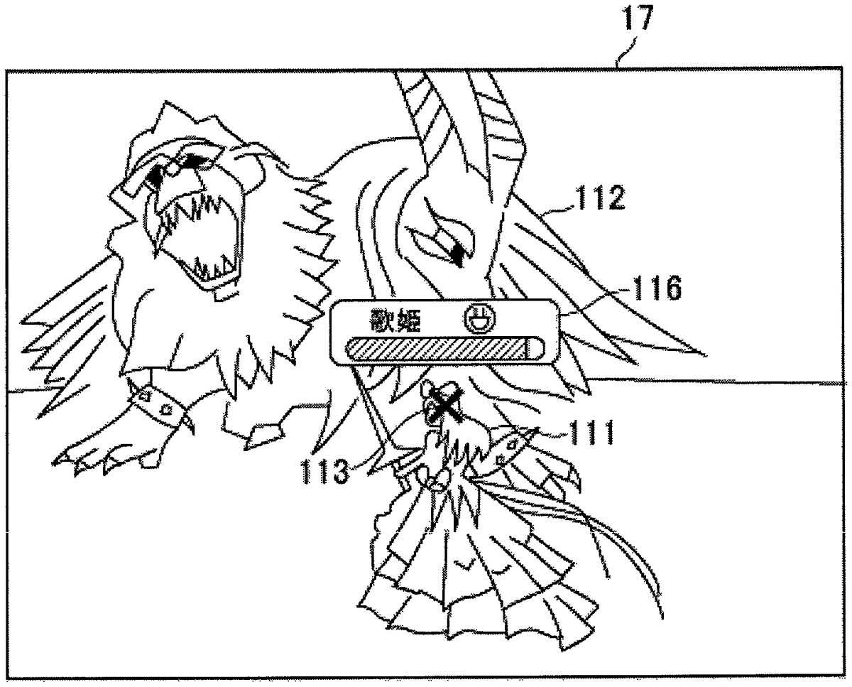
FIGS. 9A and 9Bare diagrams for describing the concept of the intersection of the line of sight of the player and the object in the virtual space, corresponding to at least one of the embodiments of the present invention.FIG. 9Ais an example of a situation where the line of sight of the player and the character intersect in a virtual battle. The character111other than the player character, the enemy character112, the point113indicating the line-of-sight direction of the player, and information116on the character111, which is displayed from the result of intersection between the line of sight and the character111are displayed on the display screen17.
FIG. 9Bis a bird's eye view showing a schematic positional relationship between the character111and the point113in the situation ofFIG. 9A. The point113indicating the line-of-sight direction is displayed at a predetermined distance from the player in the front direction of the player wearing the display device1. Furthermore, the determination area114is set for the character111in advance. The line115connecting the display device1and the point113is a line indicating a direction assumed to be viewed by the player in the virtual space.
The point113is illustrated at a position further than the distance from the player to the character111inFIG. 9B, but the point113is shown before the character111inFIG. 9A. When it is determined that the line of sight of the player intersects the character111, the information116on the character111is displayed on the display screen17. The information116includes, for example, a name and an attribute of the character, an icon representing the condition of the character, a physical fitness value representing the physical strength of the character, a psychological value indicating the energy of the character, or the like.
The information116is not visible in the real world, but is necessary information for causing the game to progress, it is preferable that the information116is displayed only in a case where the line of sight is directed toward the object. By doing as described above, it is possible to perform screen display control with higher preference without impairing the sense of immersion of the player.
Further, the setting of the determination area114for determining the intersection for displaying the information in a case of intersection with the line of sight of the player will be described.FIGS. 10A and 10Bare diagrams for describing a method of setting an area for determining intersection with the line of sight of the player in the virtual world, corresponding to at least one of the embodiments of the present invention.
FIG. 10Ashows the determination area114set for a humanoid character. It is preferable to set the determination area114corresponding to the shape of the character. However, it has difficulties in terms of an increase of the load of the determination process due to the complicated shape, and the human cost of setting the determination area.
Therefore, as shown inFIG. 10A, a sphere including the humanoid character can be defined to be the determination area114. The center point of the sphere may be calculated from the coordinate position indicating the size of the humanoid character, or in the case where the humanoid character is displayed by a polygon, the vertex of the specific bone may be the center point. By doing as described above, it is possible to determine the line of sight to the character, without causing the player to feel uncomfortable, and to reduce the load of the determination process.
On the other hand, if the determination area is set as a sphere in an extremely long character or the like in one direction, the determination area is expanded to a space far away from the character, and information related to the character is additionally displayed even in the space where the character clearly is not present, which can cause the player to feel uncomfortable. Therefore, as shown inFIG. 10B, a plurality of determination areas114can be set for each part of the body. More specifically, determination areas114ato114fare set in the head portion, the body portion, the left and right arm portions, and the left and right leg portions, respectively. By doing as described above, it is possible to set the determination area114while suppressing the load of the determination process and the development cost, and it is possible to display the information without causing the player to feel uncomfortable.
For determining the intersection of a line segment and an object in a three-dimensional space, for example, a method for obtaining an intersection point of an object and a ray (light ray) can be used in a ray tracing method. Other methods can be used, and the present invention is not limited by an intersection determination method.
As a game to which the embodiment of the present invention can be applied, for example, a role playing game (RPG) in which a plurality of characters appear, or a game that the player proceeds by knowing information on an object present in the virtual world like a treasure hunting is preferred, but it is not limited thereto. The present invention can be applied to massively multiplayer online (MMO) type games in which an unspecified number of players participate through the Internet.
In the embodiment of the present invention, the light beam for specifying the positions of the display device1and the controller4is a laser beam, for example, infrared ray, but the light beam is not limited to this, and the light beam may be visible light rays or invisible light rays.
In the embodiment of the present invention, an aspect is described in which an image is generated in a manner that can be viewed in a case where the line of sight intersects the object, but the present invention is not limited thereto. In other words, any aspect may be used as long as it can be recognized by human perception. For example, in a case where the line of sight intersects the object, sound may be generated in an aspect that can be recognizable by auditory sense.
As an aspect of the embodiment of the present invention, in a case where the line of sight of the player intersects the object, it is possible to suppress a decrease in the sense of immersion in the game of the player, by displaying information.
As an aspect of the embodiment of the present invention, by setting the intersection determination area as a sphere, the load of the determination process can be reduced, and the cost for setting the determination area can be reduced.
In the embodiment of the present invention, examples of the “display device” includes a device called a head mount display (HMD). “Being mounted on the head” refers to covering the head like a hat, attaching to the face like eyeglasses, or attaching to other parts of the head, and it is a concept including a case extending from a part of the body to cover the head as well. “Direction” is a concept including not only the direction and angle of an object, but also the direction relating to a change amount per unit time such as acceleration. “Virtual space” is, for example, a space defined by programs and data, and is a virtual space generated by a computer.
In the embodiment of the present invention, “irradiation device” is, for example, a device that irradiates light within a predetermined range, and it does not matter whether the range is narrow or wide. “Virtual camera” refers to, for example, a viewpoint or an angle of view when drawing computer graphics which are analogous to a camera. “Visual axis” refers to, for example, the axis of the line of sight of the virtual camera. “Object” refers to, for example, a tangible object present in the virtual space.
“Information associated with an object” refers to, for example, information on physical strength, state, attribute, and the like of another character, information on an item, and other types of information related to object data. “Adding information associated with an object” refers to, for example, adding added information in an aspect that can be recognized by human perception. “Reference point” refers to, for example, the center point of a sphere including an object.
APPENDIX
The above embodiments have been described such that the following invention can be carried out by those having ordinary knowledge in the field to which the present invention belongs.
(1) A display system including a display device which is used by being mounted on the head of a player, comprising: a virtual camera specifier that specifies a visual axis and/or a position of a virtual camera in a virtual space, according to a direction and/or a position of the display device; and a displayer that displays an object present in the virtual space, on the display device, according to the visual axis and/or the position of the virtual camera, wherein in a case where there is an object on the visual axis specified by the virtual camera specifier, the displayer additionally displays information associated with the object.
(2) The display system according to (1), wherein a predetermined area is set for the object, wherein the system further includes a game determiner that determines whether or not the predetermined area which is set for the object and the visual axis of the virtual camera intersect each other, and wherein in a case where the game determiner determines that the predetermined area and the visual axis intersect each other, it is determined that there is an object on the visual axis, and the displayer additionally displays information associated with the object.
(3) The display system according to (1) or (2), wherein in a case where the game determiner determines that the predetermined area and the visual axis do not intersect each other, because the visual axis and/or the position of the virtual camera change after the game determiner determines that the predetermined area and the visual axis intersect each other, the displayer hides the information associated with the displayed object.
(4) The display system according to any one of (1) to (3), wherein the predetermined area which is set for the object is a sphere centered on a reference point set in the object.
(5) A display method executed in a display system comprising a display device which is used by being mounted on the head of a player, and a computer device, comprising: a virtual camera specifying step of specifying a visual axis and/or a position of a virtual camera in a virtual space, according to a direction and/or a position of the display device; and a display step of displaying an object present in the virtual space, on the display device, according to the visual axis and/or the position of the virtual camera, wherein in the display step, in a case where there is an object on the visual axis specified in the virtual camera specifying step, information associated with the object is additionally displayed.
(6) A computer device capable of being connected to a display device which is used by being mounted on the head of a player, by communication, comprising: a virtual camera specifier that specifies a visual axis and/or a position of a virtual camera in a virtual space, according to a direction and/or a position of the display device; and a displayer that displays an object present in the virtual space, on the display device, according to the visual axis and/or the position of the virtual camera, wherein in a case where there is an object on the visual axis specified by the virtual camera specifier, the displayer additionally displays information associated with the object.
REFERENCE SIGNS LIST
1DISPLAY DEVICE11CONTROL UNIT12RAM13STORAGE14IMAGING UNIT15GRAPHICS PROCESSOR16DISPLAY UNIT17DISPLAY SCREEN18SENSOR UNIT18aPROXIMITY SENSOR18bINFRARED SENSOR18cGYROSENSOR18dACCELERATION SENSOR19COMMUNICATION INTERFACE2IRRADIATION DEVICE20INTERFACE UNIT21LENS3COMPUTER DEVICE4CONTROLLER5COMMUNICATION NETWORK31CONTROL UNIT32RAM33STORAGE34SOUND PROCESSOR35GRAPHICS PROCESSOR36DVD/CD-ROM37COMMUNICATION INTERFACE38INTERFACE UNIT39FRAME MEMORY40SOUND OUTPUT DEVICE41DISC51DISPLAY DEVICE52IMAGING DEVICE53COMPUTER DEVICE54CONTROLLER
Claims
- A display system including a display device configured to be mounted on a head of a player, the display system comprising: a virtual camera processor that specifies a visual axis of a virtual camera in a virtual space according to a direction of the display device, and that determines a line of sight of the player based on posture information of the display device;a game processor;and the display device, when a virtual game character is determined to intersect with the line of sight of the player, extracts game character status information of the virtual game character and displays the extracted game character status information of the virtual game character, the virtual game character being present in the virtual space according to the visual axis of the virtual camera, wherein the game character status information associated with the virtual game character includes information on a state or attribute of the player's virtual game character, wherein the game character status information is displayed near the virtual game character, wherein an image is generated for display on the display device based on an input received on a controller device, the controller device being separate from the display device, wherein a plurality of predetermined areas is set for the virtual game character, wherein the game processor determines that the virtual game character intersects with the line of sight of the player when at least one of the plurality of predetermined areas set for the virtual game character intersects with the line of sight of the player, wherein each of the predetermined areas set for the virtual game character is a sphere, and wherein a plurality of spheres representing the plurality of the predetermined areas is set for a plurality of body parts of the virtual game character.
- The display system according to claim 1 , wherein, in a case where the game processor determines that the at least one of the plurality of predetermined areas set for the virtual game character and the line of sight of the player do not intersect each other, the display device hides from display the game character status information associated with the displayed virtual game character.
- The display system according to claim 1 , wherein each of the plurality of spheres is centered on a reference point set in the virtual game character.
- The display system according to claim 1 , wherein the game character status information and the virtual game character are separated such that they do not overlap one another.
- The display system according to claim 1 , wherein the game character status information is displayed to the player having mounted the display device on the player's head.
- The display system according to claim 1 , wherein the display device displays the game character status information only when the at least one of the plurality of predetermined areas set for the virtual game character intersects with the line of sight of the player, such that the game character status information is not displayed when the at least one of the plurality of predetermined areas set for the virtual game character does not intersect with the line of sight of the player.
- The display system according to claim 1 , wherein the display device displays the game character status information only during a time when the at least one of the plurality of predetermined areas set for the virtual game character intersects with the line of sight of the player, such that the game character status information is removed from display when the at least one of the plurality of predetermined areas set for the virtual game character no longer intersects with the line of sight of the player.
- The display system according to claim 1 , wherein an action performed by the virtual game character is controlled by the controller device, while the game character status information is extracted by the display device.
- The display system according to claim 1 , wherein the game character status information is displayed adjacent to the virtual game character when the at least one of the plurality of predetermined areas set for the virtual game character intersects with the line of sight of the player, and the game character status information is hidden from display when the at least one of the plurality of predetermined areas set for the virtual game character does not intersect with the line of sight of the player.
- The display system according to claim 1 , wherein the plurality of the spheres is set for the virtual game character not to overlap each other.
- The display system according to claim 1 , wherein the plurality of the spheres includes spheres of different sizes.
- The display system according to claim 1 , wherein at least one of the plurality of the spheres is larger than a corresponding body part of the virtual game character to include entirety of the corresponding body part.
- The display system according to claim 1 , wherein at least one of the plurality of spheres includes a portion of the body part but not an entirety of the corresponding body part.
- A display method executed in a display system including a display device configured to be mounted on a head of a player, and a computer device, the method comprising: specifying, by a virtual camera processor, a visual axis of a virtual camera in a virtual space according to a direction of the display device;determining, by the virtual camera processor, a line of sight of the player based on posture information of the display device;when a virtual game character is determined to intersect with the line of sight of the player, extracting, by the display device, game character status information of the virtual game character, the virtual game character being present in the virtual space according to the visual axis of the virtual camera;and displaying, on the display device, the extracted game character status information of the virtual game character, wherein the game character status information associated with the virtual game character includes information on a state or attribute of the player's virtual game character, wherein the game character status information is displayed near the virtual game character, wherein an image is generated for display on the display device based on an input received on a controller device, the controller device being separate from the display device, wherein a plurality of predetermined areas is set for the virtual game character, wherein the virtual game character is determined to intersect with the line of sight of the player when at least one of the plurality of predetermined areas set for the virtual game character intersects with the line of sight of the player, wherein each of the predetermined areas set for the virtual game character is a sphere, and wherein a plurality of spheres representing the plurality of the predetermined areas is set for a plurality of body parts of the virtual game character.
- A computer device configured to connect, by communication, to a display device configured to be mounted on a head of a player, the computer device comprising: a virtual camera processor that specifies a visual axis of a virtual camera in a virtual space according to a direction of the display device, and that determines a line of sight of the player based on posture information of the display device;a game processor;and the display device, when a virtual game character is determined to intersect with the line of sight of the player, extracts game character status information of the virtual game character and displays the extracted game character status information of the virtual game character, the virtual game character being present in the virtual space according to the visual axis of the virtual camera, wherein the game character status information associated with the virtual game character includes information on a state or attribute of the player's virtual game character, wherein the game character status information is displayed near the virtual game character, wherein an image is generated for display on the display device based on an input received on a controller device, the controller device being separate from the display device, wherein a plurality of predetermined areas is set for the virtual game character, wherein the game processor determines that the virtual game character intersects with the line of sight of the player when at least one of the plurality of predetermined areas set for the virtual game character intersects with the line of sight of the player, wherein each of the predetermined areas set for the virtual game character is a sphere, and wherein a plurality of spheres representing the plurality of the predetermined areas is set for a plurality of body parts of the virtual game character.
Disclaimer: Data collected from the USPTO and may be malformed, incomplete, and/or otherwise inaccurate.