U.S. Pat. No. 10,799,790
PADDLE ACCESSORY FOR A GAME CONTROLLER
AssigneeMicrosoft Technology Licensing, LLC
Issue DateFebruary 14, 2019
Illustrative Figure
Abstract
A paddle accessory includes a blade, a sensor-activation feature extending from the blade, and a mounting interface spaced apart from the sensor-activation feature. The blade is sized and shaped for manual manipulation by a finger. The mounting interface is configured to selectively mate with a pivot of a game controller to removably affix the paddle accessory to the game controller. The paddle accessory is configured to rotate relative to the pivot to translate a touch force applied to the blade into an actuation force applied by the sensor-activation feature to a paddle-actuatable sensor interior an aperture of the game controller.
Description
DETAILED DESCRIPTION Some game controllers include a plurality of controls (e.g., joystick, directional pad, action buttons) located on a thumb-side of the game controller. These controls may be configured to be manually manipulated by thumbs of a user gripping the game controller with two hands. In such a configuration, during the course of gameplay, a scenario may occur where a user desires to manipulate multiple controls with the same thumb. For example, a user may want to press an action button while at the same time manipulating a joystick. In this scenario, the user may be forced to take his thumb off the joystick in order to press the action button, and the joystick may move away from a desired manipulation posture, thus reducing control accuracy. Furthermore, some game controllers may include a plurality of controls located on a finger-side of the game controller that opposes the thumb-side of the game controller. The plurality of controls located on the finger-side may be configured to be manipulated by fingers other than thumbs (e.g., middle fingers, ring fingers, pinky fingers) of a user gripping the game controller with two hands. In some cases, the plurality of controls located on the finger-side and some of the action buttons located on the thumb-side may be actuated to generate control signals that are mapped to the same game operations. Such a configuration can alleviate the scenario where the user has to remove their thumb from the joystick to press an action button, for example. Instead, the user can press a corresponding control on the finger-side of the game controller using a finger other than the thumb, so that the thumb can remain on the joystick. Typically, such game controllers are shaped/sized to fit an average hand size of a population of users. Likewise, the controls ...
DETAILED DESCRIPTION
Some game controllers include a plurality of controls (e.g., joystick, directional pad, action buttons) located on a thumb-side of the game controller. These controls may be configured to be manually manipulated by thumbs of a user gripping the game controller with two hands. In such a configuration, during the course of gameplay, a scenario may occur where a user desires to manipulate multiple controls with the same thumb. For example, a user may want to press an action button while at the same time manipulating a joystick. In this scenario, the user may be forced to take his thumb off the joystick in order to press the action button, and the joystick may move away from a desired manipulation posture, thus reducing control accuracy.
Furthermore, some game controllers may include a plurality of controls located on a finger-side of the game controller that opposes the thumb-side of the game controller. The plurality of controls located on the finger-side may be configured to be manipulated by fingers other than thumbs (e.g., middle fingers, ring fingers, pinky fingers) of a user gripping the game controller with two hands. In some cases, the plurality of controls located on the finger-side and some of the action buttons located on the thumb-side may be actuated to generate control signals that are mapped to the same game operations. Such a configuration can alleviate the scenario where the user has to remove their thumb from the joystick to press an action button, for example. Instead, the user can press a corresponding control on the finger-side of the game controller using a finger other than the thumb, so that the thumb can remain on the joystick.
Typically, such game controllers are shaped/sized to fit an average hand size of a population of users. Likewise, the controls located on the finger-side that are integral to the game controller may be designed according to a “one size fits all” approach. However, users may have preferences on the shape, size, position and texture of such controls that differ from the standard controls that are integral to the game controller. Moreover, some users may prefer to manipulate controls on just the thumb-side of the game controller without having controls located on the finger-side of the game controller.
Accordingly, the present disclosure relates to paddle accessories configured to be removably affixable to a game controller without the use of tools. Furthermore, the present disclosure relates to a game controller including a plurality of pivots configured to removably affix a selected number of paddle accessories to the game controller. Each pivot may be configured to translate a touch applied to a corresponding paddle accessory to an actuation of a paddle-actuatable sensor.
Such a game controller may enable a different number (e.g., 0, 2, 4) of paddle accessories to be removably affixed to the game controller. Moreover, the game controller may enable differently configured paddle accessories to be quickly and easily swapped on the game controller without the use of tools. For example, such a configuration may facilitate the use of differently configured paddle accessories (e.g., having a different size or different orientation) by different users.
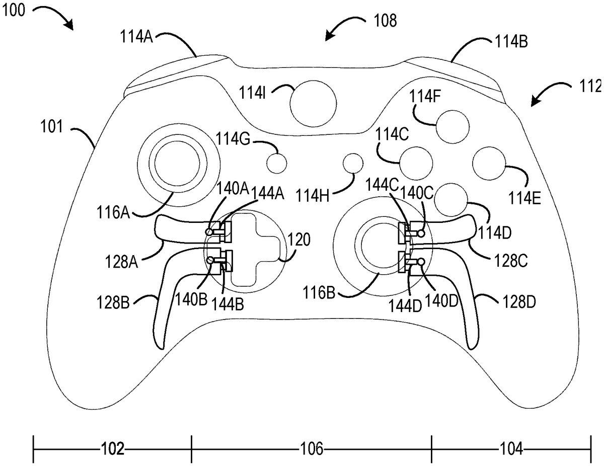
FIGS. 1-4show an example user input control device in the form of a game controller100. The game controller100may be configured to translate user input into control signals that are provided to a computing device, such as a gaming console. The control signals may be mapped to commands to control a video game or perform other operations. For example, the game controller100may be configured to send control signals via a wired or wireless connection with a computing device.
The game controller100includes a grip101configured to be held with two hands. As such, the grip101includes a left-hand portion102configured to be gripped by a left hand and a right-hand portion104configured to be gripped by a right hand. The right-hand portion104may oppose the left-hand portion102. Further, a central portion106may be positioned intermediate the left-hand portion102and the right-hand portion104.
When a user holds the controller with two hands such that the left hand grips the left-hand portion102and the right hand grips the right-hand portion104, the user's thumbs may naturally interface with a thumb-side108of the grip101. Further, the user's fingers other than the thumb (e.g., at least a ring finger and a pinky finger) may interface with a finger-side110of the grip101.
The game controller100includes a plurality of controls112configured to generate different control signals responsive to finger manipulation. The plurality of controls112may be integral to the game controller100such that the controls cannot be removed without dismantling the game controller100. Although in some implementations, one or more of the plurality of controls112may be removably affixable to the game controller100.
In the depicted implementation, the plurality of controls112includes a plurality of action buttons114(e.g.,114A,114B,114C,114D,114E,114F,114G,114H, and114I), a plurality of joysticks116(e.g., a left joystick116A and a right joystick116B), a plurality of triggers118(e.g., a left trigger118A and a right trigger118B), and a directional pad120. A majority of the controls are positioned on the thumb-side108of the game controller100(e.g., the plurality of triggers118are positioned intermediate the thumb-side108and the finger-side110). As such, the plurality of controls112typically may be manipulated by a user's thumbs. Although, in some cases, a user may manipulate one or more of the plurality of controls112with an index finger. The game controller100may include any suitable number of controls. The game controller100may include any suitable type of controls.
A printed circuit board122may be located in an interior cavity200(shown inFIG. 5) of the grip101. The printed circuit board122may include a plurality of electronic input sensors124. The plurality of electronic input sensors124may correspond to the plurality of controls112. In particular, each electronic input sensor may be configured to generate a control signal responsive to interaction with a corresponding control.
For example, each of the plurality of action buttons114may be configured to activate a corresponding electronic input sensor to generate a control signal responsive to being depressed (e.g., via finger manipulation). In another example, each of the plurality of joysticks116may interact with electronic input sensors in the form of potentiometers that use continuous electrical activity to provide an analog input control signal based on a position of the joystick in relation to a default “center” position. In another example, each of the triggers118may be configured to interact with an electronic input sensor to provide a variable control signal based on a position of the trigger relative to a default position. For example, as a trigger is pulled farther away from the default position, a characteristic of the generated control signal may increase in magnitude. In another example, the directional pad120may be configured to activate different electronic input sensors corresponding to different directions (e.g., up, down, left, right) responsive to the directional pad being depressed in the different directions.
Non-limiting examples of electronic input sensors may include dome switches, tactile switches, potentiometers, Hall Effect sensors, and other electronic sensing components. The game controller100may include any suitable number of electronic input sensors. The game controller100may include any suitable type of electronic input sensors.
The game controller100includes a plurality of pivots126(e.g.,126A,126B,126C,126D ofFIG. 3) accessible on the finger-side110of the grip101. The plurality of pivots126may be configured to removably affix a plurality of paddle accessories128(e.g.,128A,128B,128C,128D) to the game controller100. In particular, each pivot126may be configured to selectively mate with a mounting interface202(shown inFIG. 5) of a selected paddle accessory128to removably affix the selected paddle accessory128to the game controller100.
In the depicted implementation, the plurality of pivots126are located in the interior cavity200of the grip101. A plurality of pivot rims130(e.g.,130A,130B,130C,130D ofFIG. 3) located on the grip101form a plurality of pivot apertures132(e.g.,132A,132B,132C,132D) through which the plurality of pivots126are accessible to interface with selected paddle accessories. In particular, a selected paddle accessory128may be inserted into a selected pivot aperture132to interface with a selected pivot126to removably affix the selected paddle accessory128to the game controller100.
The plurality of pivots126may be recessed from the plurality of pivot apertures133. Moreover, each pivot aperture132may be sized to prevent admittance of a finger through the pivot aperture132. In other words, the pivot aperture132can be sized such that a finger cannot pass through the aperture into the interior cavity200of the grip101. Accordingly, when a paddle accessory is not removably affixed to a selected pivot, the selected pivot126does not interfere with fingers of a user holding the game controller100.
The game controller100includes a plurality of paddle-actuatable sensors134(e.g.,134A,134B,134C,134D ofFIG. 3) located on the printed circuit board122. A plurality of sensor rims136(e.g.,136A,136D,136D ofFIG. 3) may be located on the grip101and spaced apart from the plurality of pivot rims130. The plurality of sensor rims136may form a plurality of sensor apertures138(e.g.,138A,138B,138C,138D ofFIG. 3) through which the plurality of paddle-actuatable sensors134are accessible to interface with selected paddle accessories. In particular, when a selected paddle accessory128is removably affixed to a selected pivot126, a touch force applied to the selected paddle accessory128outside the apertures of the game controller100(e.g., the plurality of pivot apertures132and the plurality of sensor apertures138) may be translated to an actuation force applied by the selected paddle accessory128to a corresponding paddle-actuatable sensor134. The plurality of paddle accessories128each may include a sensor activation feature140(e.g.,140A,140B,140C,140D ofFIG. 2) configured to interface with a corresponding paddle-actuatable sensor134to apply the actuation force when the selected paddle accessory128rotates responsive to the touch force.
The plurality of paddle-actuatable sensors134may be recessed from the plurality of sensor apertures138. Moreover, each sensor aperture138may be sized to prevent admittance of a finger through the sensor aperture138. In other words, the sensor aperture138can be sized such that a finger cannot pass through the sensor aperture138into the interior cavity200of the grip101. Accordingly, paddle-actuatable sensors134within the interior cavity200of the grip101are less likely to be accidentally activated by user fingers, because the small aperture size blocks the user fingers from engaging the paddle-actuatable sensors134.
In the depicted implementation, the plurality of pivots126and the plurality of paddle-actuatable sensors134are arranged such that each paddle-actuatable sensor134is positioned closer to a hand portion than a corresponding pivot126. For example, the paddle-actuatable sensors134A and134B may be positioned closer to the left-hand portion102than the pivots126A and126B. Likewise, the paddle-actuatable sensors134C and134D may be positioned closer to the right-hand portion104than the pivots126C and126D. Such an arrangement may cause a paddle accessory128that is removably affixed to a pivot126to extend laterally from the pivot126toward a hand portion (e.g., the left-hand portion102or the right-hand portion104).
By positioning the paddle accessories128laterally along the finger-side110of the game controller100, the paddle accessories128may extend towards the fingers of a user that is gripping the game controller100. Accordingly, different paddle accessories128having different lengths may be swapped out to accommodate different hand sizes of different users. For example, longer paddle accessories may be removably affixed to the game controller100for a user having smaller hands and fingers that cannot reach as far. In another example, shorter paddle accessories may be removably affixed to the game controller100for a user having larger hands and fingers that can reach farther.
In the depicted implementation, anywhere from 0-4 paddle accessories may be removably affixed to the game controller100. The game controller100may include any suitable number of pivot and paddle-actuatable sensor pairs in order to accommodate any suitable number of paddle accessories. Moreover, a pivot and paddle-actuatable sensor pair may be located on any suitable portion of the game controller100. For example, in some implementations, a pivot and paddle-actuatable sensor pair may be positioned on the thumb-side108of the game controller100to removably affix a selected paddle accessory128.
In some implementations, each of the plurality of pivots126may be identically configured. Moreover, each pivot and paddle-actuatable sensor pair may be identically configured. Such a configuration may allow for a same paddle accessory128to be removably affixable to any of the plurality of pivots126. In this way, the same paddle accessory can be used at two or more different locations. Furthermore, the location of the paddle accessory can be easily changed without the use of tools.
In some implementations, the paddle-actuatable sensors134may include Hall Effect sensors that need not be physically contacted by a paddle accessory128in order to be activated. Rather, in such implementations, the selected paddle accessory128inside of the sensor aperture138moves into an actuation range of the Hall Effect sensor responsive to a touch applied to the selected paddle accessory128outside of the sensor aperture138. For example, the sensor activation feature140may include a magnet (or another material that affects a magnetic field produced by the Hall Effect sensor). Further, the pivot126may be configured to allow the paddle accessory128to rotate responsive to a touch being applied to the selected paddle accessory128to move the sensor-activation feature140towards the Hall Effect sensor in order to influence the magnetic field produced by the Hall Effect sensor such that an output signal produced by the Hall Effect sensor is affected. In other words, the sensor activation feature140may cause the Hall Effect sensor to produce an activation signal without physically contacting the sensor. In another example, the sensor-activation feature of the selected paddle accessory128moves away from the Hall Effect sensor responsive to a touch being applied to the selected paddle accessory outside of the sensor aperture138to influence the magnetic field produced by the Hall Effect sensor such that the Hall Effect sensor produces an activation signal.
In some implementations, the plurality of pivot rims130may define a plurality of mating slots142(e.g.,142A,142B,142C,142D ofFIG. 2). Each mating slot may be configured to receive a stabilization fin144(e.g.,144A,144B,144C,144D) of a selected paddle accessory128that is removably affixed to a corresponding pivot126. In particular, the selected paddle accessory128may rotate relative to the corresponding pivot126along a first axis responsive to a touch force being applied to the selected paddle accessory128. The mating slot142may be sized to prevent the stabilization fin144from rotating about an axis different than the first axis during rotation of the selected paddle accessory128. For example, the mating slot142may have a width that is slightly greater than a width of the stabilization fin144. In this way, the interaction of the stabilization fin144with the mating slot142may effectively prevent the selected paddle accessory128from twisting when being depressed.
Furthermore, the stabilization fin144of the selected paddle accessory128may be sized to extend into the corresponding mating slot142even when the selected paddle accessory128is in a default posture where no touch force is applied to rotate the selected paddle accessory128. Further, when the selected paddle accessory128rotates responsive to a touch force, the stabilization fin144may move further into the mating slot142relative to when the selected paddle accessory128is in the default posture. In other words, the stabilization fin144may move from a first depth in the mating slot142to a second depth in the mating slot142that is greater than the first depth responsive to the touch force being applied to the selected paddle accessory128.
The pivot126may include any suitable structure configured to removably affix a selected paddle accessory128to the game controller100.FIG. 5shows an example pivot126A including a magnet125configured to magnetically affix the paddle accessory128A to the game controller100. Such an implementation may be referred to herein as a magnetic pivot. In particular, the paddle accessory128A may include a mounting interface202made at least partially of ferromagnetic material to magnetically affix the paddle accessory128A to the pivot126A of the game controller100. In some implementations, the paddle accessory128may be a single metal ferromagnetic part. For example, the ferromagnetic part may be injection-molded metal. In another example, the ferromagnetic part may be machined from a single piece of metal. In other implementations, the paddle accessory128may be an assembly of different pieces (e.g., mounting interface and blade).
The magnet125may be located in the interior cavity200of the game controller100as defined by the grip101. For example, the magnet125may be coupled to the grip101via pressure-sensitive adhesive. To affix the paddle accessory128A to the magnet125, the paddle accessory128A may be inserted through the pivot aperture132A defined by the pivot rim130A. Moreover, the stabilization fin144A may be inserted into the mating slot142A. An example approach for manipulating the paddle accessory128A to affix the paddle accessory128A to the magnet125is shown inFIGS. 7-9and is discussed in more detail below.
When the mounting interface202is magnetically affixed to the magnet125, the paddle accessory128A may be positioned such that the sensor-activation feature140A extends into the sensor aperture138A to interface with the paddle-actuatable sensor134A. In the illustrated example, the sensor-activation feature140A includes a projection, and the paddle-actuatable sensor134A includes a tactile switch. In particular, the sensor-activation feature140A may extend from a blade204of the paddle accessory128such that the sensor-activation feature140A is spaced apart from the mounting interface202. Such a configuration enables the paddle accessory128A to translate a touch force applied to the blade204at an exterior206of the game controller100into an actuation force applied by the sensor-activation feature140A to the paddle-actuatable sensor134A in the interior cavity200. In this way, a touch force applied outside of the pivot aperture132A and the sensor aperture138A actuates the paddle-actuatable sensor134A. For example, the paddle accessory128A may rotate relative to the pivot126A responsive to the touch force being applied to the blade204, such that the sensor-activation feature140A moves towards the paddle-actuatable sensor134A and applies a suitable amount of pressure to actuate the paddle-actuatable sensor134A.
In some implementations, the game controller100may include one or more electrostatic discharge shields210(e.g.,210A,210B ofFIG. 6) to electrically insulate internal electronic components (e.g., electronic components located on the printed circuit board122of the game controller100) from the magnets126and other sources of electrical interference.FIG. 6shows a top view of the printed circuit board122with the electrostatic discharge shields210A and210B drawn in dashed lines to reveal the plurality of paddle accessories128magnetically affixed to the plurality of pivots126. The plurality of paddle-actuatable sensors134are positioned on an underside of the printed circuit board122so that the plurality of paddle-actuatable sensors134may be accessible to the plurality of paddle accessories128.
FIG. 7-9show an example approach for removably affixing the paddle accessory128A to the pivot126A that includes the magnet. InFIG. 7, the paddle accessory128A is oriented in a first position to allow the mounting interface202to be inserted into the pivot aperture132A. In the first position, the blade204is askew relative to the grip such that the blade204is almost perpendicular to the grip101.
InFIG. 8, the paddle accessory128A has been inserted through the pivot aperture132A far enough into the interior cavity200for the mounting interface202to clear the pivot130A rim. Once the mounting interface202has cleared the aperture rim130A, the paddle accessory128A may be rotated (e.g., approximately ninety degrees) from the first position to a second position where the mounting interface202mates with the pivot126A to magnetically affix the paddle accessory128A to the game controller100.
InFIG. 9, the paddle accessory128A is oriented in the second position with the blade204being aligned to follow the contour of the grip101(e.g., extending substantially parallel with the grip101). In the second position, the stabilization fin144A is inserted in the mating slot142A defined by the pivot rim130A and extends into the interior cavity200. Further, the sensor-activation feature140A extends into the sensor aperture138A to interface with the paddle-actuatable sensor134A (not shown inFIGS. 7-9for purposes of visual clarity). Note that the same approach may be performed in reverse order to remove the paddle accessory128A from the game controller100.
FIGS. 10-11show the paddle accessory128A rotating to apply an actuation force to the paddle-actuatable sensor134A responsive to a touch force being applied to the paddle accessory128A. InFIG. 10, the paddle accessory128A is in a default posture in which no touch force is applied to the blade204. In the default posture, the mounting interface202aligns vertically with the pivot126A such that the mounting interface202is flush with the pivot126A. Further, in the default posture, the sensor-activation feature140A extends into the interior cavity200, but the sensor-activation feature140A is spaced apart from the paddle-actuatable sensor134A. In some implementations, the sensor-activation feature140A may touch the paddle-actuatable sensor134A, but without applying enough force to cause the paddle-actuatable sensor134A to actuate. The magnetic attraction between the pivot126A and the mounting interface202may maintain the paddle accessory in the default posture when no touch force is applied to the paddle accessory128A.
InFIG. 11, the paddle accessory128A is rotated to an actuation posture responsive to a touch input force being applied to the blade204. In the actuation posture, the mounting interface202rotates relative to the pivot126A such that the mounting interface202is not flush with the pivot126A. In one configuration, in the actuation posture, the sensor-activation feature140A extends further into the interior cavity200relative to the default posture. In the actuation posture, the sensor-activation feature140A presses the paddle-actuatable sensor134A with an actuation force sufficient to actuate the paddle-actuatable sensor134A. When the touch input force is no longer applied to the blade204, the magnetic attraction between the pivot126A and the mounting interface202may return the paddle accessory128A from the actuation posture to the default posture. In some implementations, auxiliary springs and/or other biasing devices may be used to increase a return force applied to the paddle accessory128A.
FIG. 12shows another example pivot1200configured to magnetically affix a paddle accessory1202to a game controller1204. The paddle accessory1202may include a mounting interface1206that is made of ferromagnetic material magnetically attracted to the pivot1200. The pivot1200may be oriented in the game controller1204such that a retention interface1208of the pivot1200is oriented at approximately a forty-five degree angle. Likewise, the mounting interface1206may be shaped to have an angle that cooperates with the angle of the retention interface1208to affix the paddle accessory1202flush with the pivot1200. Such a configuration differs from the pivot126A and the mounting interface202which has a vertical retention interface. The slanted orientation of the retention interface1208may adjust a range of angular rotation of the paddle accessory1202towards the game controller1204. A pivot may be oriented at any suitable angle relative to the game controller to removably affix a paddle accessory to the game controller.
FIGS. 13-15show another example pivot1300configured to removably affix a paddle accessory1302to a game controller1304. The pivot1300comprises a spring-biased hook that includes a spring1306and a hook1308(shown inFIGS. 14-15). The spring1306may be positioned and biased to span a pivot aperture1312defined by a pivot rim1318located on a grip1316when no paddle accessory is affixed to the spring-biased hook1300. InFIG. 14, the paddle accessory1302is oriented in a first position to allow a mounting interface1310to be inserted into the pivot aperture1312. The mounting interface1310may be pushed into an interior cavity1314of the game controller1304suitably far enough to interact with the spring1306. In particular, the mounting interface1310may be inserted with enough force to overcome a spring force of the spring1306and bend the spring1306away from the pivot aperture1312far enough to allow the mounting interface1310to clear the hook1308. Once the mounting interface1310has cleared the hook1308, the paddle accessory1302may be rotated (e.g., approximately ninety degrees) from the first position to a second position where the hook1308mates with the mounting interface1310.
InFIG. 15, the paddle accessory1302is oriented in the second position where the mounting interface1310mates with the hook1308. Moreover, the spring1306is biased to apply the spring force to the paddle accessory1302to pinch the paddle accessory1302against the grip1316and removably affix the paddle accessory1302to the game controller1304.
The pivot1300may have a low profile within the interior cavity. The pivot1300may be installed on the grip1316without adhesive. Since the pivot1300does not affix the paddle accessory1302via a magnetic attraction, the paddle accessory1302need not include ferromagnetic material.
FIGS. 16-17show another example pivot1600including a magnet1603configured to removably affix a paddle accessory1601to a game controller1602. In particular, the paddle accessory1601has a mounting interface1604that includes a magnet1606that is magnetically attracted to the magnet1603. The magnet1606may be coupled to a blade1608of the paddle accessory1601. By employing the magnet1606in the paddle accessory1601, the blade1608need not be made of ferromagnetic material. For example, the blade1608instead may be injected-molded plastic.
InFIG. 16, the paddle accessory1601is oriented in a first position to allow the mounting interface1604to be inserted into a pivot aperture1610defined by a pivot rim1611located on a grip1612of the game controller1602. In the first position, the blade1608may be askew relative to the grip1612. The paddle accessory1601may be inserted through the pivot aperture1610far enough for the mounting interface1604to clear the pivot1600. Once the mounting interface1604has cleared the pivot1600, the paddle accessory1601may be rotated (e.g., approximately ninety degrees) from the first position to a second position where the magnet1606mates with the magnet1603to magnetically affix the paddle accessory1601to the game controller1602.
InFIG. 17, the paddle accessory1601is oriented in the second position with the magnet1606mated flush with the magnet1603, and the blade1608is aligned to follow the contour of the grip1612. Further, a sensor-actuation feature1614extends into a sensor aperture1616defined by a sensor rim1617located on the grip1612to interface with a paddle-actuatable sensor1618. Note that the same approach may be performed in reverse order to remove the paddle accessory128A from the game controller100.
FIG. 18shows another example pivot1800configured to removably affix a paddle accessory1802to a game controller1804. The pivot1800includes a socket1806and a spring1808. The socket1806may be accessible through a pivot aperture1812defined by a pivot rim1814located on a grip1816of the game controller1804. In particular, the paddle accessory1802includes a mounting interface1810having a rounded head configured to mate with the socket1806. In one example, the rounded head may be cylindrical and the socket1806may be a C-clamp. The mounting interface1810may be initially inserted into the socket1806with enough force to overcome a spring force of the spring1808. In other words, the spring1808may be pushed aside to allow the mounting interface1810to enter the socket1806. Further, when the mounting interface1810is fully inserted into the socket1806, the spring1808may apply a spring force to the mounting interface1810to affix the paddle accessory1802to the game controller1804. The rounded mounting interface1810and the socket1806may collectively form a hinge about which the paddle accessory1802may rotate.
In other such implementations, the spring1808may be replaced by another fastener. For example, such fastener may include a snap, an elastic member, temporarily deformable resilient material (e.g., foam or rubber), or another type of fastener.
FIG. 19shows another example pivot1900configured to removably affix a paddle accessory1902to a game controller1904. The pivot1900includes a socket1906, a first magnet1908, and a second magnet1910. The first magnet1908may be positioned to generate a magnetic field in the X direction, and the second magnet1910may be positioned to generate a magnetic field in the Y direction. The socket1906may be accessible through a pivot aperture1912defined by a pivot rim1914located on a grip1916of the game controller1904. The socket1906may be sized or otherwise configured to accommodate a mounting interface1918of the paddle accessory1902. The mounting interface1918may have a rounded head configured to mate with the socket1906. In one example, the rounded head may be cylindrical and the socket1906may be a C-clamp. In one example, the socket1906may be configured to be temporarily deformable responsive to insertion of the mounting interface1918with an insertion force great enough to temporarily deform the socket1906.
Further, the mounting interface1918may be made at least partially of ferromagnetic material that is magnetically attracted to the first magnet1908and the second magnet1910. In particular, when the mounting interface1918is inserted into the socket1906, the first and second magnets1908and1910generate a collective magnetic field that affixes the paddle accessory1902to the game controller1904. The rounded mounting interface1918and the socket1906may collectively form a hinge about which the paddle accessory1902may rotate.
In other such implementations, the first magnet1908and the second magnet1910may be placed in other orientations. For example, one or more of the magnets may be orientated such that the pole of the one or more magnets may be substantially perpendicular to a central axis of a cylinder of the mounting interface1918.
In other such implementations, the magnets and the ferromagnetic material may be swapped. For example, the first magnet1908and the second magnet1910alternatively may be made of ferromagnetic material, and the mounting interface1918may include a magnet that is magnetically attracted to the ferromagnetic material.
In the implementation illustrated inFIG. 19, the mounting interface1918of the paddle accessory1912may be inserted into the pivot aperture1912a selected distance in the Y direction in order to interface with the socket1906to affix the paddle accessory1902to the game controller1904. In other such implementations, the pivot1900may be configured such that once the paddle accessory1902is inserted in the pivot aperture1912, the paddle accessory1902may be shifted in the X direction (e.g., at a diagonal angle) in order to insert the mounting interface1918into the socket1906. Once the mounting interface1918is secured in the socket1906, the paddle accessory1902may be rotated ninety degrees to align the activation feature with the paddle actuatable sensor.
FIGS. 20-21show another example pivot2000configured to removably affix a paddle accessory2002to a game controller2004. The pivot2000includes a socket2006and a magnet2008. In particular, the socket2006may be positioned at an exterior2010of a grip2012. Further, the grip2012includes a hand portion2016(e.g., corresponding to the left-hand portion102or the right-hand portion104of the game controller100) configured to be gripped by a hand. A rim2018located on the grip2012defines a sensor aperture2020. A paddle-actuatable sensor2022may be positioned in an interior cavity2024of the grip2012such that the paddle-actuatable sensor2022is accessible through the sensor aperture2020. In particular, the paddle-actuatable sensor2022may be located on a printed circuit board2026that is coupled to an interior side2028of the grip2012. The sensor aperture2020may be spaced apart from the pivot2000such that the pivot2000is positioned closer to the hand portion2016than the paddle-actuatable sensor.
The paddle accessory2002includes a blade2032. A rounded mounting interface2014and a sensor-activation feature2030extend from the blade2032. To removably affix the paddle accessory2002to the game controller2004, the sensor-activation feature2030may be inserted through the sensor aperture2020, and the paddle accessory2002may be inserted far enough into the interior cavity2024for the sensor-activation feature2030to clear the paddle-actuatable sensor2022. Once the sensor-activation feature2030has cleared the paddle-actuatable sensor2022, the paddle accessory2002may be rotated such that the rounded mounting interface2014mates with the socket2006. The rounded mounting interface2014may be made at least partially of ferromagnetic material that is magnetically attracted to the magnet2008. Such a magnetic attraction may affix the rounded mounting interface2014to the socket2006. The rounded mounting interface2014and the socket2006may collectively form a hinge about which the paddle accessory2002may rotate.
InFIG. 20, the paddle accessory2002is in a default posture in which no touch force is applied to the blade2032. In the default posture, the sensor-activation feature2030is spaced apart from the paddle-actuatable sensor2022. In some implementations, the sensor-activation feature2030may touch the paddle-actuatable sensor2022, but without applying enough force to cause the paddle-actuatable sensor2022to actuate. The magnetic attraction between the magnet2008and the rounded mounting interface2014may maintain the paddle accessory2002in the default pressure when no touch force is applied to the paddle accessory2002.
InFIG. 21, the paddle accessory2002is rotated to an actuation posture responsive to a touch input force2034being applied to the blade2032. In the actuation posture, the mounting interface2014rotates relative to the socket2006. Further, in the actuation posture, the sensor-activation feature2030rotates to apply an actuation force2036to the paddle-actuatable sensor2022. The actuation force2036may be sufficient to actuate the paddle-actuatable sensor2022. When the touch input force2034is no longer applied to the blade204, the magnetic attraction between the magnet2008and the rounded mounting interface2014may return the paddle accessory2002from the actuation posture to the default posture.
In some implementations, a rim of the pivot aperture and/or other surfaces of the game controller configured to interact with the paddle accessory may include a low-friction material that allows the paddle accessory to slide into the pivot aperture and/or allows the paddle accessory to affix to the pivot. For example, the rim around the pivot aperture may include a polished surface that differs from a texture of an exterior surface of the game controller that may have a higher-friction surface configured to be gripped by a hand.
In other implementations, the game controller may include a mounting platform configured to rigidly, removably affix a paddle accessory to the game controller. In other words, the mounting platform may not allow the paddle accessory to pivot responsive to a touch force being applied to the paddle accessory. Rather, the paddle accessory may be configured to flex or deform responsive to a touch force being applied to the paddle accessory to interact with a paddle-actuatable sensor.
FIG. 22shows an example paddle accessory2200configured to be removably affixed to a game controller having a paddle-actuatable sensor that is positioned closer to a hand portion than a pivot, such as the game controller100shown inFIG. 1. The paddle accessory2200includes a blade2202sized and shaped for manual manipulation by a finger. The blade2202may be curved to follow a contour of a hand portion of the game controller.
A sensor-activation feature2204, herein depicted as a projection, extends from the blade2202and may be configured to selectively interact with a paddle-actuatable sensor recessed within a sensor aperture of the game controller. In particular, the projection may be configured to extend into the sensor aperture of the game controller to interface with the paddle-actuatable sensor when the paddle accessory2200rotates responsive to user input.
A mounting interface2206may be spaced apart from the sensor-activation feature2204along the blade2202. In particular, when the paddle accessory2200is removably affixed to a game controller, the sensor-activation feature2204may be positioned closer to a hand portion of the game controller than the mounting interface2206. The mounting interface2206may be configured to selectively mate with a pivot of the game controller to removably affix the paddle accessory2200to the game controller. In particular, the mounting interface2206may be made at least partially of ferromagnetic material configured to magnetically affix the paddle accessory2200to a pivot of the game controller. The paddle accessory2200may be configured to rotate relative to the pivot to translate a touch force applied to the blade2202into an actuation force applied by the sensor-activation feature2204to the paddle-actuatable sensor interior the aperture of the game controller.
A stabilization fin2208may be positioned between the sensor-activation feature2204and the mounting interface2206. The stabilization fin2208may be configured to extend into a mating slot of the game controller. The mating slot may be sized to prevent the stabilization fin2208from rotating about an axis different than an axis of rotation of the mounting interface2206relative to the pivot of the game controller. In other words, interaction of the stabilization fin2208with the mating slot of the game controller may prevent the paddle accessory2200from twisting when being depressed by a finger of a user.
FIG. 23shows an example paddle accessory2300configured to be removably affixed to a game controller having a pivot that is positioned closer to a hand portion than a paddle-actuatable sensor, such as the game controller2004shown inFIG. 20. The paddle accessory2300includes a blade2302sized and shaped for manual manipulation by a finger. The blade2302may be curved to follow a contour of a hand portion of the game controller.
A sensor-activation feature2304, herein depicted as a ledge, extends from the blade2302and may be configured to selectively interact with a paddle-actuatable sensor of the game controller. In particular, the ledge may be configured to be inserted into a sensor aperture and rotated to be position over the paddle-actuatable sensor.
A mounting interface2306may be spaced apart from the sensor-activation feature2304along the blade2302. In particular, when the paddle accessory2300is removably affixed to a game controller, the mounting interface2306may be positioned closer to a hand portion of the game controller than the sensor-activation feature2304. The mounting interface2306may be configured to selectively mate with a pivot of the game controller to removably affix the paddle accessory2300to the game controller. In particular, the mounting interface2306may be made at least partially of ferromagnetic material configured to magnetically affix the paddle accessory2300to a pivot of the game controller. Further, the mounting interface2306may be rounded to selectively mate with a socket formed by the pivot. In such a configuration, the rounded mounting interface2306and the socket may collectively form a hinge about which the paddle accessory2300rotates relative to the pivot to translate a touch force applied to the blade2302into an actuation force applied by the sensor-activation feature2304to the paddle-actuatable sensor interior the aperture of the game controller.
A stabilization fin2308may be positioned between the sensor-activation feature2304and the mounting interface2306. The stabilization fin2308may be configured to extend into a mating slot of the game controller. The mating slot may be sized to prevent the stabilization fin2308from rotating about an axis different than an axis of rotation of the mounting interface2306relative to the pivot of the game controller. In other words, interaction of the stabilization fin2308with the mating slot of the game controller may prevent the paddle accessory2300from twisting when being depressed by a finger of a user.
Different paddle accessories may be configured differently to provide different gameplay experiences. For example, different paddle accessories may have blades of different dimensions including different lengths, widths, and curvatures. In some implementations, a blade may include one or more bends and/or one or more twists relative to the portion of the paddle accessory on which the mounting interface and/or the sensor-activation feature are located. For example, a blade may bend at 25°, 45°, 60°, 90°, 120°, or at another angle. In another example, a blade may be twisted upwards toward the triggers or downwards toward the directional pad. For example, a blade may be twisted at 25°, 45°, 60°, 90°, 120°, or at another angle. In another example, a blade may include a combination of one or more bends and one or more twists.
As another example, different paddle accessories may have blades having different cross-sectional shapes including circular or elliptical shapes, angular shapes including shapes having squared-off corners, and other suitable shapes. As another example, different paddles may have blades having different degrees of convexity or concavity. As another example, different paddle accessories may have different textures including smooth textures, rough textures, or other suitable textures. Some textures may be formed from different material coatings applied to the blade. Other textures may be formed by a structure of the blade itself.
In another example implementation, a paddle accessory for a game controller comprises a blade sized and shaped for manual manipulation by a finger, a sensor-activation feature extending from the blade, and a mounting interface spaced apart from the sensor-activation feature. The mounting interface may be configured to selectively mate with a pivot of the game controller to removably affix the paddle accessory to the game controller. The paddle accessory may be configured to rotate relative to the pivot to translate a touch force applied to the blade into an actuation force applied by the sensor-activation feature to a paddle-actuatable sensor interior an aperture of the game controller. In one example implementation that optionally may be combined with any of the features described herein, the mounting interface is positioned between the sensor-activation feature and the blade. In one example implementation that optionally may be combined with any of the features described herein, the sensor-activation feature is positioned between the mounting interface and the blade. In one example implementation that optionally may be combined with any of the features described herein, the blade is curved to follow a contour of a hand portion of the game controller that is configured to be gripped by a hand. In one example implementation that optionally may be combined with any of the features described herein, the mounting interface includes a magnet configured to magnetically affix the paddle accessory to a magnet of the pivot. In one example implementation that optionally may be combined with any of the features described herein, the mounting interface is made at least partially of ferromagnetic material to magnetically affix the paddle accessory to a magnet of the pivot. In one example implementation that optionally may be combined with any of the features described herein, the mounting interface includes a rounded head configured to mate with a socket of the pivot to collectively form a hinge. In one example implementation that optionally may be combined with any of the features described herein, the sensor-activation feature includes a projection configured to extend into an aperture of the game controller to apply the actuation force to the paddle-actuatable sensor responsive to the touch force being applied to the blade. In one example implementation that optionally may be combined with any of the features described herein, the paddle accessory comprises a stabilization fin positioned between the sensor-activation feature and the mounting interface. The stabilization fin may be configured to extend into a mating slot of the game controller. In one example implementation that optionally may be combined with any of the features described herein, the stabilization fin extends a first depth into the mating slot when no touch force is applied to the blade. The stabilization fin extends a second depth into the mating slot responsive to the touch force being applied to the blade. The second depth may be greater than the first depth.
In another example implementation, a paddle accessory for a game controller comprises a blade sized and shaped for manual manipulation by a finger, a sensor-activation feature extending from the blade, and a mounting interface spaced apart from the sensor-activation feature. The mounting interface may be made at least partially of ferromagnetic material to magnetically affix the paddle accessory to a magnetic pivot of the game controller. The paddle accessory may be configured to rotate relative to the magnetic pivot to translate a touch force applied to the blade into an actuation force applied by the sensor-activation feature to a paddle-actuatable sensor interior an aperture of the game controller. In one example implementation that optionally may be combined with any of the features described herein, the mounting interface is positioned between the sensor-activation feature and the blade. In one example implementation that optionally may be combined with any of the features described herein, the sensor-activation feature is positioned between the mounting interface and the blade. In one example implementation that optionally may be combined with any of the features described herein, the blade is curved to follow a contour of a hand portion of the game controller that is configured to be gripped by a hand. In one example implementation that optionally may be combined with any of the features described herein, the mounting interface includes a rounded head configured to mate with a socket of the pivot to collectively form a hinge. In one example implementation that optionally may be combined with any of the features described herein, the sensor-activation feature includes a projection configured to extend into an aperture of the game controller to apply the actuation force to the paddle-actuatable sensor responsive to the touch force being applied to the blade. In one example implementation that optionally may be combined with any of the features described herein, the paddle accessory comprises a stabilization fin positioned between the sensor-activation feature and the mounting interface, the stabilization fin configured to extend into a mating slot of the game controller.
In another example implementation, a paddle accessory for a game controller comprises a blade curved to follow a contour of a hand portion of the game controller that is configured to be gripped by a hand, the blade being sized and shaped for manual manipulation by a finger, a sensor-activation feature extending from the blade, a mounting interface spaced apart from the sensor-activation feature, and a stabilization fin positioned between the sensor-activation feature and the mounting interface. The mounting interface may be configured to selectively mate with a pivot of the game controller to removably affix the paddle accessory to the game controller. The paddle accessory may be configured to rotate relative to the pivot to translate a touch force applied into the blade to an actuation force applied by the sensor-activation feature to the paddle-actuatable sensor. The stabilization fin may be configured to extend into a mating slot of the game controller. In one example implementation that optionally may be combined with any of the features described herein, the stabilization fin extends a first depth into the mating slot when no touch force is applied to the blade. The stabilization fin extends a second depth into the mating slot responsive to the touch force being applied to the blade, the second depth being greater than the first depth. In one example implementation that optionally may be combined with any of the features described herein, the mounting interface is made at least partially of ferromagnetic material to magnetically affix the paddle accessory to a magnet of the pivot.
It will be understood that the configurations and/or approaches described herein are exemplary in nature, and that these specific embodiments or examples are not to be considered in a limiting sense, because numerous variations are possible. The specific routines or methods described herein may represent one or more of any number of processing strategies. As such, various acts illustrated and/or described may be performed in the sequence illustrated and/or described, in other sequences, in parallel, or omitted. Likewise, the order of the above-described processes may be changed.
The subject matter of the present disclosure includes all novel and nonobvious combinations and subcombinations of the various processes, systems and configurations, and other features, functions, acts, and/or properties disclosed herein, as well as any and all equivalents thereof.
Claims
- A paddle accessory for a game controller, the paddle accessory comprising: a blade sized and shaped for manual manipulation by a finger and including a bend angled to follow a contour of a surface of the game controller;a sensor-activation feature extending from the blade;and a mounting interface connected to the blade and spaced apart from the sensor-activation feature, the mounting interface being configured to rigidly, removably affix the paddle accessory to the game controller such that the paddle accessory flexes in response to a touch force to translate the touch force applied to the blade into an actuation force applied by the sensor-activation feature to a paddle-actuatable sensor of the game controller.
- The paddle accessory of claim 1 , wherein the paddle-actuatable sensor is positioned interior an aperture of the game controller, and wherein the sensor-activation features is sized to extend into the aperture to interface with the paddle-actuatable sensor when the paddle accessory flexes in response to the touch force.
- The paddle accessory of claim 1 , wherein the mounting interface is configured to be inserted into an aperture of the game controller to rigidly, removably affix the paddle accessory to the game controller.
- The paddle accessory of claim 1 , wherein the blade is concave.
- The paddle accessory of claim 1 , wherein the blade is flat.
- The paddle accessory of claim 1 , further comprising: a stabilization fin configured to extend from the blade into a mating slot of the game controller.
- A paddle accessory for a game controller, the paddle accessory comprising: a blade sized and shaped for manual manipulation by a finger and including a bend angled to follow a contour of a surface of the game controller;a sensor-activation feature extending from the blade;and a mounting interface connected to the blade and spaced apart from the sensor-activation feature, the mounting interface being configured to rigidly, removably affix the paddle accessory to the game controller such that the paddle accessory flexes in response to a touch force to translate the touch force applied to the blade into an actuation force applied by the sensor-activation feature to a paddle-actuatable sensor interior an aperture of the game controller, wherein the sensor-activation feature is sized to extend into the aperture to interface with the paddle-actuatable sensor when the paddle accessory flexes in response to the touch force.
- The paddle accessory of claim 7 , wherein the mounting interface is configured to be inserted into an aperture of the game controller to rigidly, removably affix the paddle accessory to the game controller.
- The paddle accessory of claim 7 , wherein the blade is concave.
- The paddle accessory of claim 7 , wherein the blade is flat.
- The paddle accessory of claim 7 , further comprising: a stabilization fin configured to extend from the blade into a mating slot of the game controller.
- A game controller, comprising: a grip including a left-hand portion configured to be gripped by a left hand, a right-hand portion configured to be gripped by a right hand, and a central portion intermediate the left-hand portion and the right-hand portion;a rim located on the grip, the rim defining an aperture;a paddle-actuatable sensor positioned interior the aperture;and a paddle including a blade and a sensor-activation feature extending from the blade, wherein the paddle is rigidly affixed to the central portion of the gripgamc controller such that the paddle extends laterally from the central portion towards the left-hand portion or the right-hand portion and flexes in response to a touch force to translate the touch force applied to the blade into an actuation force applied by the sensor-activation feature to the paddle-actuatable sensor, and wherein the sensor-activation feature is sized to extend into the aperture to interface with the paddle-actuatable sensor when the paddle flexes in response to the touch force.
- The game controller of claim 12 , further comprising: a plurality of paddle-actuatable sensors;and a plurality of paddles, each paddle including a blade and a sensor-activation feature extending from the blade, wherein each paddle is rigidly affixed to the game controller such that the paddle flexes in response to a touch force to translate the touch force applied to the blade into an actuation force applied by the sensor-activation feature to a corresponding paddle-actuatable sensor of the plurality of paddle-actuatable sensors.
- The game controller of claim 12 , wherein the grip includes a thumb-side and a finger-side opposite the thumb-side, and wherein the paddle is affixed to the finger-side.
- The game controller of claim 12 , wherein the paddle-actuatable sensor includes a tactile switch.
- The game controller of claim 12 , wherein the paddle-actuatable sensor includes a Hall Effect sensor.
Disclaimer: Data collected from the USPTO and may be malformed, incomplete, and/or otherwise inaccurate.