U.S. Pat. No. 10,758,817
Game Controller
Issue DateJuly 9, 2018
Illustrative Figure
Abstract
The inventive game controller has a base portion and an upper portion. The base portion and the upper portion are constructed and arranged so that the base portion is stationary relative to the upper portion; and when the upper portion is moved parallel to the base portion, the game controller translates the relative motion of the upper portion to the base portion into programmable keystrokes or analog movements, which in turn correspond to movements with the game; the upper portion moving forward relative to the base portion translates to forward movement in the game; the upper portion moving backwards relative to the base portion translates to backwards movement in the game; the upper portion moving left or twisting left relative to the base portion translates to spinning; left or strafing left in the game; the upper portion moving right or twisting right relative to the base portion translates to right spinning or right strafing in the game. The upper portion has a palm portion, a raised portion over which the fingers extend, and a plurality of user defined function keys arranged in at least one row. The upper portion having a palm portion, a raised portion over which the fingers extend, and a plurality of user defined function keys arranged in three rows, with the row closest to the palm portion raised higher than the other two rows, so that arching a finger allows striking the front two rows of keys, while flattening the finger allows striking the back raised key. An electronic device is electrically connected to the plurality of user defined function keys, and there is a connector for connecting the game controller to a computer (or a part of a computer, like the keyboard).
Description
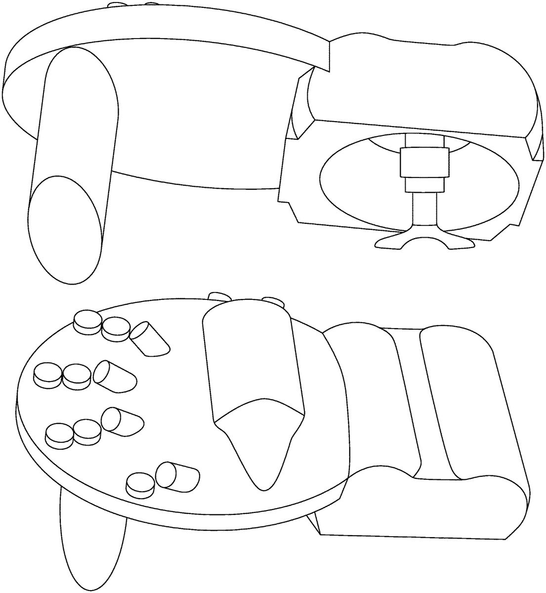
DETAILED DESCRIPTION OF THE INVENTION While this invention may be embodied in many forms, there are described in detail herein specific embodiments of the invention. This description is an exemplification of the principles of the invention and is not intended to limit the invention to the particular embodiments illustrated. For the purposes of this disclosure, like reference numerals in the figures shall refer to like features unless otherwise indicated. Referring now toFIG. 1, a view of a working 3D printed game controller prototype, with the base portion on the left and the upper portion on the right, showing the bottom side of the upper portion is shown generally at10. The base portion12is designed to be stationary while the upper portion14is designed to move two dimensionally parallel to the bottom portion12, when assembled together as shown best inFIG. 2. The bottom portion12has projections16and20which cooperate with key pairs18and22respectively to record forward, backwards, left, right and combinations of these movements. The key pairs are electrically connected to a controller24via wires26and the controller24has a connector, which can be any commercially available connector such as a mini-USB connector, to connect the game controller to a computer or keyboard (not shown). One or more thumb switches or keys could also be provided, as shown at30. FIG. 2shows the working 3D printed game controller prototype assembled, with the upper portion14resting on the projections of the base portion, and constructed and arranged so the upper portion can move relative to the base portion, with the projections depressing the keys to translate the relative motion of the upper portion14to the lower portion12into keyboard commands which move an object or game character in a game forward, backward, left, right, or left spinning or strafing, or right spinning or strafing, or any other allowable motion permitted by a game. The upper ...
DETAILED DESCRIPTION OF THE INVENTION
While this invention may be embodied in many forms, there are described in detail herein specific embodiments of the invention. This description is an exemplification of the principles of the invention and is not intended to limit the invention to the particular embodiments illustrated.
For the purposes of this disclosure, like reference numerals in the figures shall refer to like features unless otherwise indicated.
Referring now toFIG. 1, a view of a working 3D printed game controller prototype, with the base portion on the left and the upper portion on the right, showing the bottom side of the upper portion is shown generally at10. The base portion12is designed to be stationary while the upper portion14is designed to move two dimensionally parallel to the bottom portion12, when assembled together as shown best inFIG. 2. The bottom portion12has projections16and20which cooperate with key pairs18and22respectively to record forward, backwards, left, right and combinations of these movements. The key pairs are electrically connected to a controller24via wires26and the controller24has a connector, which can be any commercially available connector such as a mini-USB connector, to connect the game controller to a computer or keyboard (not shown). One or more thumb switches or keys could also be provided, as shown at30.
FIG. 2shows the working 3D printed game controller prototype assembled, with the upper portion14resting on the projections of the base portion, and constructed and arranged so the upper portion can move relative to the base portion, with the projections depressing the keys to translate the relative motion of the upper portion14to the lower portion12into keyboard commands which move an object or game character in a game forward, backward, left, right, or left spinning or strafing, or right spinning or strafing, or any other allowable motion permitted by a game. The upper portion also has three rows of keys, which are schematically shown in the 3D printed prototype, with the front row being commercially available mechanical keyswitches from Cherry Americas, shown at28. In the working version, the three rows of keys would preferably be configured and tilted at an angle to make it easy and comfortable to depress with fingers of a left hand (in this version). A right handed game controller is also contemplated. The keys can be any commercially available key, or could be
FIG. 3shows a dome switch membrane.
FIG. 4shows an alternative embodiment in which the palm portion of the upper portion is adjustable. In the prototype, it is shown as pegs which slot into holes, to move the palm portion32towards or away from the rows of keys. In this embodiment, there is also a support34to hold four keys which are actuated with the top (or back) of the fingers, by lifting the finger up to depress the key. Once again, the keys can be any commercially available type of key and are electrically connected to the controller to communicate programmable key strokes to the game. The programming for the keys are either stored in the gaming device keyboard or they can be stored on the individual computer they are connected to.
FIGS. 5 and 6shows the alternative embodiment in the assembled state. In addition to the palm portion32, there is also a raised portion36, which provides a finger rest, for comfort.
FIG. 7shows a side view of the embodiment ofFIGS. 4-6, and the 3D printed schematic for the keys or switches is shown at38. In the working version, keys or switches38would be positioned so they can be activated by the back of the four fingers, one button or key per finger.
FIG. 8shows a closer view of the finger rest raised portion36, with the schematic view of the three rows of keys in front of the finger rest raised portion36.
FIG. 9-13shows an alternative embodiment for a 3D joystick type control. The joystick control sits on four keys and the upper portion is moved, which causes the control to depress on or more of the keys, to control movement of an object or game character in a game forward, backward, left, right, or left spinning or strafing, or right spinning or strafing, or any other allowable motion permitted by a game.
FIG. 14shows an alternate embodiment which includes three rows of keys with the row50closest to the palm raised above the other two rows, and two rows51and53furthest from the palm. There is also a finger separator plate52.
FIG. 15shows an exemplary hand placement with the finger separator between the ring finger and the middle finger.
FIG. 16shows the index finger arched forward to reach the forward most row of keys.
FIG. 17shows the index finger straightened or flattened out so enable striking the raised rearmost key, shown at53. In use, the users fingers arch over to reach the front and second rows of keys51and53and the user presses the row50keys be straightening out a finger and pressing down with the portion of the finger between the middle knuckle and the palm knuckle. The row50keys are raised above the row51and53keys to enable the pressing of the row50keys as described above.
FIG. 18shows slightly smaller projections from the base portion which operate the same as described above.
FIG. 19shows a side view showing the thumb key, the circuit board and the wired connector which is attached to the circuit board and which connects the controller to the game platform or computer.
FIG. 20shows another alternate embodiment with two rails54onto which a an adjustable palm portion slides using slots56(upside down in this picture to show the slots).
FIG. 21shows the slots partially slid onto the rails.
FIG. 22shows the palm portion prior to being slid onto the rails.
It should be understood that the features of the various embodiments can be incorporated together, as desired. For example, the riser34and back finger keys38ofFIGS. 4-7could be combined with the finger separator52ofFIG. 14and/or the raised keys of row50ofFIGS. 14 and 17.
Claims
- A game controller comprising: a base portion;an upper portion;the base portion and the upper portion constructed and arranged so that the base portion is stationary relative to the upper portion;and when the upper portion is moved parallel to the base portion, the game controller translates the relative motion of the upper portion to the base portion into programmable keystrokes or analog movements, which in turn correspond to movements with the game;the upper portion moving forward relative to the base portion translates to forward movement in the game;the upper portion moving backwards relative to the base portion translates to backwards movement in the game;the upper portion moving left or twisting left relative to the base portion translates to spinning left or strafing left in the game;the upper portion moving right or twisting right relative to the base portion translates to right spinning or right strafing in the game;the upper portion having a palm portion, a raised portion over which the fingers extend, and a plurality of user defined function keys arranged in at least one row;an electronic device electrically connected to the plurality of user defined function keys, and a connector for connecting the game controller to a computer.
- The game controller of claim 1 wherein there are three rows of four user defined function keys.
- The game controller of claim 2 wherein there is a thumb switch on the side of the raised portion.
- A game controller controller comprising: a base portion;an upper portion;the base portion and the upper portion constructed and arranged so that, the base portion is stationary relative to the upper portion;and when the upper portion is moved parallel to the base portion, the game controller translates the relative motion of the upper portion to the base portion into programmable keystrokes or analog movements, which in turn correspond to movements with the game;the upper portion moving forward relative to the base portion translates to forward movement in the game;the upper portion moving backwards relative to the base portion translates to backwards movement in the game;the upper portion moving left or twisting left relative to the base portion translates to spinning left or strafing left in the game;the upper portion moving right or twisting right relative to the base portion translates to right spinning or right strafing in the game;the upper portion having a palm portion, a raised portion over which the fingers extend, and a plurality of user defined function keys arranged in at least one row;an electronic device electrically connected to the plurality of user defined function keys, a connector for connecting the game controller to a computer, and further including a plurality of user defined back finger actuated function keys carried above the plurality of user defined function keys.
- The game controller of claim 4 further including a position sensor for controlling the position of an object or player-character in a game, the position sensor being electrically connected to the computer or electronic device.
- The game controller of claim 5 wherein the upper portion repositions itself back to a center position when the user releases tension from the device.
- The game controller of claim 6 wherein the position sensor is comprised of a projection from the base portion and a pair of buttons under the upper portion which interact with the projection and control the forward and backwards position of the object in the game, by movement of the upper portion forward and backward relative to the base portion.
- The game controller of claim 7 further including a second projection from the base portion and a second pair of buttons under the upper portion which interact with the second projection and control the side to side position of the object in the game, by movement of the upper portion side to side relative to the base portion.
- The game controller of claim 4 further including a joystick sensor for controlling the position of an object in a game, the joystick sensor being electrically connected to the electronic device.
- The game controller of claim 9 wherein the joystick sensor is comprised of a joystick portion connected to the base portion which is comprised of four keyboard keys and which fits into am opening on the bottom of the upper portion.
- The game controller of claim 4 wherein the palm portion can be adjustably connecting to the base portion to accommodate different hand sizes.
- The game controller of claim 1 wherein an upper palm portion can be adjustably connecting to the base portion to accommodate different hand sizes.
- The game controller of claim 4 wherein the thumb portion can be adjustably connecting to the base portion to accommodate different hand sizes.
- A game controller comprising: a base portion;an upper portion;the base portion and the upper portion constructed and arranged so that the base portion is stationary relative to the upper portion;and when the upper portion is moved parallel to the base portion, the game controller translates the relative motion of the upper portion to the base portion into programmable keystrokes or analog movements, which in turn correspond to movements with the game;the upper portion moving forward relative to the base portion translates to forward movement in the game;the upper portion moving backwards relative to the base portion translates to backwards movement in the game;the upper portion moving left or twisting left relative to the base portion translates to spinning left or strafing left in the game;the upper portion moving right or twisting right relative to the base portion translates to right spinning or right strafing in the game;the upper portion having a palm portion, a raised portion over which the fingers extend, and a plurality of user defined function keys arranged in three rows, with the row closest to the palm portion raised higher than the other rows;so that arching a finger allows striking the front two rows of keys, while flattening the finger allows striking the back raised key;an electronic device electrically connected to the plurality of user defined function keys, a connector for connecting the game controller to a computer, and further wherein the rows of keys are arranged into a plurality of columns and further including a finger separator plate arranged between two of the plurality of columns.
- The game controller of claim 14 further including a support connected to the controller to hold a plurality of user defined back finger actuated function keys carried above the three rows of user defined function keys, which are actuated by raising a finger to depress one of the user defined back finger actuated function keys by pushing upwards on the key.
Disclaimer: Data collected from the USPTO and may be malformed, incomplete, and/or otherwise inaccurate.