U.S. Pat. No. 10,751,621
METHOD AND SYSTEM FOR RENDERING VIDEO GAME IMAGES
AssigneeSquare Enix Limited
Issue DateSeptember 1, 2017
Illustrative Figure
Abstract
A method comprises producing image frames representing evolution of a scene in a field of view of a virtual camera in a virtual environment; and rendering in the image frames an appearance of movement of an environment element in the scene in correspondence with movement of the virtual camera within the virtual environment. In another method the virtual environment may include a virtual camera, an object of interest and an environment element of which at least a portion is located between the virtual camera and the object of interest. The method may comprise producing a sequence of image frames representing evolution of a scene, and over the course of multiple image frames, rendering an appearance of movement of the portion of the environment element to expose more of the object of interest in at least part of the scene previously occupied by the portion of the environment element that was moved.
Description
DETAILED DESCRIPTION FIG. 1is a block diagram illustrating a configuration of a game apparatus1implementing an example non-limiting embodiment of the present invention. In some cases, the game apparatus1is a dedicated gaming console similar to an Xbox™, Playstation™, or Nintendo™ gaming console. In other cases, the game apparatus1is a multi-purpose workstation or laptop computer. In still other cases, the game apparatus1is a mobile device such as a smartphone. In yet other cases, the game apparatus1is a handheld game console. The game apparatus1includes at least one processor10, at least one computer readable memory11, at least one input/output module15and at least one power supply unit27, and may include any other suitable components typically found in a game apparatus used for playing video games. The various components of the game apparatus1may communicate with each other over one or more buses, which can be data buses, control buses, power buses and the like. As shown inFIG. 1, a player7is playing a game by viewing game images displayed on a screen of a display device5and controlling aspects of the game via a game controller3. Accordingly, the game apparatus1receives inputs from the game controller3via the input/output module15. The game apparatus1also supplies outputs to the display device5and/or an auditory device (e.g., a speaker, not shown) via the input/output module15. In other implementations, there may be more than one game controller3and/or more than one display device5connected to the input/output module15. The processor10may include one or more central processing units (CPUs) having one or more cores. The processor10may also include at least one graphics processing unit (GPU) in communication with a video encoder/video codec (coder/decoder, not shown) for causing output data to be supplied to the input/output module15for display on the display device5. The processor10may also include at least one audio processing unit in communication with an audio encoder/audio codec ...
DETAILED DESCRIPTION
FIG. 1is a block diagram illustrating a configuration of a game apparatus1implementing an example non-limiting embodiment of the present invention. In some cases, the game apparatus1is a dedicated gaming console similar to an Xbox™, Playstation™, or Nintendo™ gaming console. In other cases, the game apparatus1is a multi-purpose workstation or laptop computer. In still other cases, the game apparatus1is a mobile device such as a smartphone. In yet other cases, the game apparatus1is a handheld game console.
The game apparatus1includes at least one processor10, at least one computer readable memory11, at least one input/output module15and at least one power supply unit27, and may include any other suitable components typically found in a game apparatus used for playing video games. The various components of the game apparatus1may communicate with each other over one or more buses, which can be data buses, control buses, power buses and the like.
As shown inFIG. 1, a player7is playing a game by viewing game images displayed on a screen of a display device5and controlling aspects of the game via a game controller3. Accordingly, the game apparatus1receives inputs from the game controller3via the input/output module15. The game apparatus1also supplies outputs to the display device5and/or an auditory device (e.g., a speaker, not shown) via the input/output module15. In other implementations, there may be more than one game controller3and/or more than one display device5connected to the input/output module15.
The processor10may include one or more central processing units (CPUs) having one or more cores. The processor10may also include at least one graphics processing unit (GPU) in communication with a video encoder/video codec (coder/decoder, not shown) for causing output data to be supplied to the input/output module15for display on the display device5. The processor10may also include at least one audio processing unit in communication with an audio encoder/audio codec (coder/decoder, not shown) for causing output data to be supplied to the input/output module15to the auditory device.
The computer readable memory11may include RAM (random access memory), ROM (read only memory), flash memory, hard disk drive(s), DVD/CD/Blu ray™ drive and/or any other suitable memory device, technology or configuration. The computer readable memory11stores a variety of information including a game program33, game data34and an operating system35.
When the game apparatus1is powered on, the processor10is configured to run a booting process which includes causing the processor10to communicate with the computer readable memory11. In particular, the booting process causes execution of the operating system35. The operating system35may be any commercial or proprietary operating system suitable for a game apparatus. Execution of the operating system35causes the processor10to generate images displayed on the display device5, including various options that are selectable by the player7via the game controller3, including the option for the player7to start and/or select a video game to be played. The video game selected/started by the player7is encoded by the game program33.
The processor10is configured to execute the game program33such that the processor10is able to perform various kinds of information processing functions related to the video game that it encodes. In particular, and with reference toFIG. 2, execution of the game program33causes the processor to execute a game data processing function22and game rendering processing function24, which are now described.
The game rendering processing function24includes generation of a game image to be displayed on the display device5. For its part, the game data processing function22includes processing of information representing progress of the game or a current state of the game (e.g., processing of information relating to the game that is not necessarily displayed on the display device5). The game data processing function22and the game rendering processing function24are illustrated inFIG. 2as forming part of a single game program33. However, in other embodiments, the game data processing function22and the game rendering processing function24may be separate programs stored in separate memories and executed by separate, possibly distant, processors. For example, the game data processing function22may be performed on a CPU and the game rendering processing function24may be performed on a GPU.
In the course of executing the game program33, the processor10manipulates constructs such as objects, characters and/or levels according to certain game rules and applying certain artificial intelligence algorithms. In the course of executing the game program33, the processor10creates, loads, stores, reads and generally accesses the game data34, which includes data related to the object(s), character(s) and/or level(s).FIG. 3shows an example illustrating examples of game data34according to a present example embodiment. The game data34may include data related to the aforementioned constructs and therefore may include object data42, level data44and/or character data46.
An object may refer to any element or portion of an element in the game environment that can be displayed graphically in a game image frame. An object may include 3-dimensional representations of buildings, vehicles, furniture, plants, sky, ground, ocean, sun, and/or any other suitable elements. The object may have other non-graphical representations such numeric, geometric or mathematical representations. The object data42stores data relating to the current representation of the object such as the graphical representation in a game image frame or a numeric, geometric or mathematical representation. The object data42may also store attributes such as imaging data, position data, material/texture data, physical state data, visibility data, lighting data (e.g., direction, position, color and/or intensity), sound data, motion data, collision data, environment data, timer data and/or other data associated with the object. Certain attributes of an object may be controlled by the game program33.
A character is similar to an object except that the attributes are more dynamic in nature and it has additional attributes that objects typically do not have. Certain attributes of a playing character may be controlled by the player7. Certain attributes of a character, be it a playing character or a non-playing character, may be controlled by the game program33. Examples of characters include a person, an avatar or an animal, to name a few non-limiting possibilities. The character may have other non-visual representations such as numeric, geometric or mathematical representations. A character may be associated with one or more objects such as a weapons held by a character or clothes donned by the character. The character data46stores data relating to the current representation of the character such as the graphical representation in a game image frame or a numeric, geometric or mathematical representation. The character data46may also store attributes such as imaging data, position data, material/texture data, physical state data, visibility data, lighting data (e.g., direction, position, color and/or intensity), sound data, motion data, collision data, environment data, timer data and/or other data associated with the character.
The game data34may also include data relating to the current view or camera angle of the game (e.g., first-person view, third-person view, etc.) as displayed on the display device5which may be part of the representations and/or attributes of the object data42, level data44and/or character data46.
In executing the game program33, the processor10may cause an initialization phase to occur after the player7has selected/started the game, causing initialization of the game. The initialization phase is used to carry out any necessary game setup and prepare the game data34for the start of the game. The game data34changes during the processing of the game program33(i.e., during the playing of the game) and the terminology “game state” is used herein to define the current state or properties of the game data34and hence the various object data42, level data44and/or character data46and their corresponding representations and/or attributes.
After the initialization phase, the processor10in execution of the game program33may implement one or more game loops. The one or more game loops run continuously during gameplay causing the game data processing function22and the game rendering processing function24to be routinely performed.
A game loop may be implemented, whereby (i) the game data processing function22is performed to process the player's input via the game controller3and to update the game state and afterwards (ii) the game rendering processing function24is performed to cause the game image to be rendered based on the updated game state for display on the display device5. The game loop may also track the passage of time to control the rate of gameplay. It should be appreciated that parameters other than player inputs can influence the game state. For example, various timers (e.g., elapsed time, time since a particular event, virtual time of day, etc.) can have an effect on the game state. In other words, the game keeps moving even when the player7isn't providing input and as such, the game state may be updated in the absence of the player's input.
In general, the number of times the game data processing function22is performed per second specifies the updates to the game state per second (hereinafter “updates per second”) and the number of times the game rendering processing function24is performed per second specifies game image rendering per second (hereinafter “frames per second”). In theory the game data processing function22and the game rendering processing function24would be called the same number of times per second. By way of a specific and non-limiting example, if the target is 25 frames per second, it would be desirable to have the game data processing function22and the game rendering processing function24both being performed every 40 ms (i.e., 1 s/25 FPS). In the case where the game data processing function22is performed and afterwards the game rendering processing function24is performed, it should be appreciated that both the game data processing function22and the game rendering processing function24would need to be performed in the 40 ms time window. Depending on the current game state, it should be appreciated that the time of performing the game data processing function22and/or the game rendering processing function24may vary. If both the game data processing function22and the game rendering processing function24take less than 40 ms to perform, a sleep timer may be used before performing the next cycle of the game data processing function22and the game rendering processing function24. However, if the game data processing function22and the game rendering processing function24take more than 40 ms to perform for a given cycle, one technique is to skip displaying of a game image to achieve a constant game speed.
It should be appreciated that the target frames per second may be more or less than 25 frames per second (e.g., 60 frames per second); however, it may be desired that the game data processing function22and the game rendering processing function24be performed not less than 20 to 25 times per second so that the human eye won't notice any lag in the rendering of the game image frames. Naturally, the higher the frame rate, the less time between images and the more powerful the processor(s) require to execute the game loop, hence the reliance on specialized processor such as GPUs.
In other embodiments, the game data processing function22and the game rendering processing function24may be separate game loops and hence independent processes. In such cases, the game data processing function22may be routinely performed at a specific rate (i.e., a specific number of updates per second) regardless of when the game rendering processing function24is performed and the game rendering processing function24may be routinely performed at a specific rate (i.e., a specific number of frames per second) regardless of when the game data processing function22.
It should be appreciated that the process of routinely performing, the game data processing function22and the game rendering processing function24may be implemented according to various techniques within the purview of the person skilled in the art and the techniques described in this document are non-limiting examples of how the game data processing function22and the game rendering processing function24may be performed.
When the game data processing function22is performed, the player input via the game controller3(if any) and the game data34is processed. More specifically, as the player7plays the video game, the player7inputs various commands via the game controller3such as move left, move right, jump, shoot, to name a few examples. In response to the player input, the game data processing function22may update the game data34. In other words, the object data42, level data44and/or character data46may be updated in response to player input via the game controller3. It should be appreciated that every time the game data processing function22is performed, there may not be any player input via the game controller3. Regardless of whether player input is received, the game data34is processed and may be updated. Such updating of the game data34may be in response to representations and/or attributes of the object data42, level data44and/or character data46as the representations and/or attributes may specify updates to the game data34. For example, timer data may specify one or more timers (e.g., elapsed time, time since a particular event, virtual time of day, etc.), which may cause the game data34(e.g., the object data42, level data44and/or character data46) to be updated. By way of another example, objects not controlled by the player7may collide (bounce off, merge, shatter, etc.), which may cause the game data34e.g., the object data42, level data44and/or character data46to be updated in response to a collision.
In general the game data34(e.g., the representations and/or attributes of the objects, levels, and/or characters) represents data that specifies a three-dimensional (3D) graphics scene of the game. The process of converting a three-dimensional (3D) graphics scene, which may include one or more 3D graphics objects, into two-dimensional (2D) rasterized game image for display on the display device5is generally referred to as rendering.FIG. 4illustrates an example of a process of converting a 3D graphics scene to a game image for display on the display device5via the screen. At step52, the game data processing function22processes the data that represents the three-dimensional (3D) graphics scene of the game and converts this data into a plurality of vertex data. The vertex data is suitable for processing by a rendering pipeline55(also known as a graphics pipeline). At step55, the game rendering processing function24processes the vertex data according to the rendering pipeline. The output of the rendering pipeline is typically pixels for display on the display device5via the screen (step60).
More specifically, at step52, the 3D graphics objects in the graphics scene may be subdivided into one or more 3D graphics primitives. A primitive may refer to a group of one or more vertices that are grouped together and/or connected to define a geometric entity (e.g., point, line, polygon, surface, object, patch, etc.) for rendering. For each of the 3D graphics primitives, vertex data is generated at this step. The vertex data of each primitive may include one or more attributes (e.g., position, the color, normal or texture coordinate information, etc.). In deriving the vertex data, a camera transformation (e.g., rotational transformations) may occur to transform the 3D graphics objects in the 3D graphics scene to the current view or camera angle. Also, in deriving the vertex data, light source data (e.g., direction, position, color and/or intensity) may be taken into consideration. The vertex data derived at this step is typically an ordered list of vertices to be sent to the rendering pipeline. The format of the ordered list typically depends on the specific implementation of the rendering pipeline.
At step55, the game rendering processing function24processes the vertex data according to the rendering pipeline. Rendering pipelines are known in the art (e.g., OpenGL, DirectX, etc.); regardless of the specific rendering pipeline used to implement the rendering pipeline, the general process of the rendering pipeline is to create a 2D raster representation (e.g., pixels) of a 3D scene. The rendering pipeline in general calculates the projected position of the vertex data in to two-dimensional (2D) screen space and performs various processing which may take into consideration lighting, colour, position information, texture coordinates and/or any other suitable process to derive the game image (e.g., pixels) for output on the display device5(step60).
In some cases, the game apparatus1is distributed between a server on the internet and one or more internet appliances. Plural players may therefore participate in the same online game, and the functionality of the game program (the game rendering processing function and/or the game data processing function) may be executed at least in part by the server.
The game environment of a video game may be a virtual environment that includes various objects such as a virtual camera, a playing character and several environment elements and other objects. A position and an angle of the camera within the virtual environment define a field of view, which would include objects in a region of the virtual environment that expands from the virtual camera generally outwards. Only a subset of the objects in the field of view of the virtual camera would be “visible” from the virtual camera and rendered on-screen for a player of the game in control of the playing character. Which objects are visible is a function of the transparency of the objects in the field of view as well as their interposition relative to the virtual camera (also referred to as their Z-buffer position).
Regarding the environment elements, some may be flexible. Examples of suitable environment elements that are flexible include objects such as a plant (including reeds, branches, leaves, vines, algae, . . . ), an inanimate object (e.g., flags, bead curtains, vertical blinds, . . . ), a corpse, etc.FIG. 5shows a corpse502and a plant504as non-limiting examples of environment elements that are flexible. As illustrated, each environment element is associated with one or more “bones” (segments) and corresponding “collision primitives” that are not rendered on-screen but are used in collision calculations, as will be described later on. For example, the plant504includes a plurality of branches, and each branch is represented by one or more bones514,516,518with a corresponding surrounding collision primitive524,526,528having a simple shape, such as a capsule (e.g., a cylinder capped at either end by a hemisphere). Similarly, the corpse502is represented by an arrangement of bones532,534,536, surrounded by corresponding capsule-like collision primitives542,544,546. When an environment element is associated with multiple bones and corresponding capsule-like collision primitives, the capsules may be of different dimensions. The radius of the hemisphere at either end of a given capsule can be a variable that is definable at runtime. In other embodiments, the collision primitives need not be capsules, and they may instead be prisms or other three-dimensional shapes.
The environment elements502,504have the property of being flexible. Moreover, there exists a natural position in the virtual environment towards which each of the environment elements may be biased, either by resilience or by gravity. For example, in the case of a resilient reed represented by a single bone, a base point is provided, around which the bone pivots. The bone has a natural position in the virtual environment and its resilience may be defined by a biasing force towards the natural position while continuously attached to the base point, which remains immobile in the virtual environment. If the biasing force is overcome by another object colliding with the bone's collision primitive, the resilient reed is rendered as swinging about the base point and, due to its resilience, the resilient reed will be caused to return to its natural position if/when the object is removed.
In more complex examples with multiple interconnected bones, such as the plant504or the corpse502ofFIG. 5, a base point is provided for each bone, around which the corresponding bone pivots, but the base point is also movable within the virtual environment. As such, during a collision, there is a transfer of forces between bones. For example, consider that the bones have a natural position and that their resilience may be defined by a biasing force towards the natural position while continuously attached to the corresponding base point. If the biasing force is overcome by another object colliding with a particular bone's collision primitive (e.g.,524,526,528,542,544,546), the associated branch, limb, etc. is rendered as swinging about the base point, but a certain fraction of the force of impact will be transmitted to other bones connected to the impacted bone. The connected bones will therefore experience motion which could further be transferred to other connected bones, and so on. If and when the object is removed, the bones may, due to their resilience, be rendered as returning to their natural positions.
In accordance with certain embodiments, a collision primitive associated with the virtual camera may collide with an environment element (or, more specifically, with its collision primitive as discussed above). Specifically, and with reference toFIG. 6, a virtual camera602is associated with its own collision primitive604(hereinafter referred to as a “camera collision primitive”) which, although not rendered on-screen, is used in collision calculations, as will be described later on. Additional details regarding the camera collision primitive604are now described with continued reference toFIG. 6. Specifically, in some embodiments, the virtual camera602is located within the camera collision primitive604(e.g., at an end thereof). In other embodiments the camera collision primitive604is located in front of the virtual camera602, between the virtual camera602and an object of interest. In one embodiment, the game is a third-person game and the object of interest is the playing character606. The virtual camera602and the playing character606may move relative to one another but the virtual camera602will continually be oriented to include the playing character606and thus the camera collision primitive604is located between the virtual camera602and the playing character606. Movement of the virtual camera602may include any of a translation of the virtual camera602within the virtual environment and a change in orientation of the virtual camera602relative to a fixed location within the virtual environment.
The camera collision primitive604may have many possible shapes, one of which is a capsuloid. A capsuloid is a 3D shape of a certain length with two ends, capped by hemispheres of potentially different radii at either end. The radius of the hemisphere at the end of the camera collision primitive604that is closer to the virtual camera602may be smaller than the radius of the hemisphere at the end of the camera collision primitive604that is closer to the playing character606. The radii of the hemispheres at the ends of the capsuloid can be variables that are definable at runtime. Also, the camera collision primitive604need not extend the length of the distance between the virtual camera602and the playing character606. Rather, the camera collision primitive604may extend only part of the length, e.g., it may end at a point that is 90%, 75%, 50%, or less than half of the distance between the virtual camera602and the playing character606. This length of the capsuloid, in either absolute terms or in terms relative to the distance between the virtual camera602and the playing character606, can be a variable that is definable at runtime.
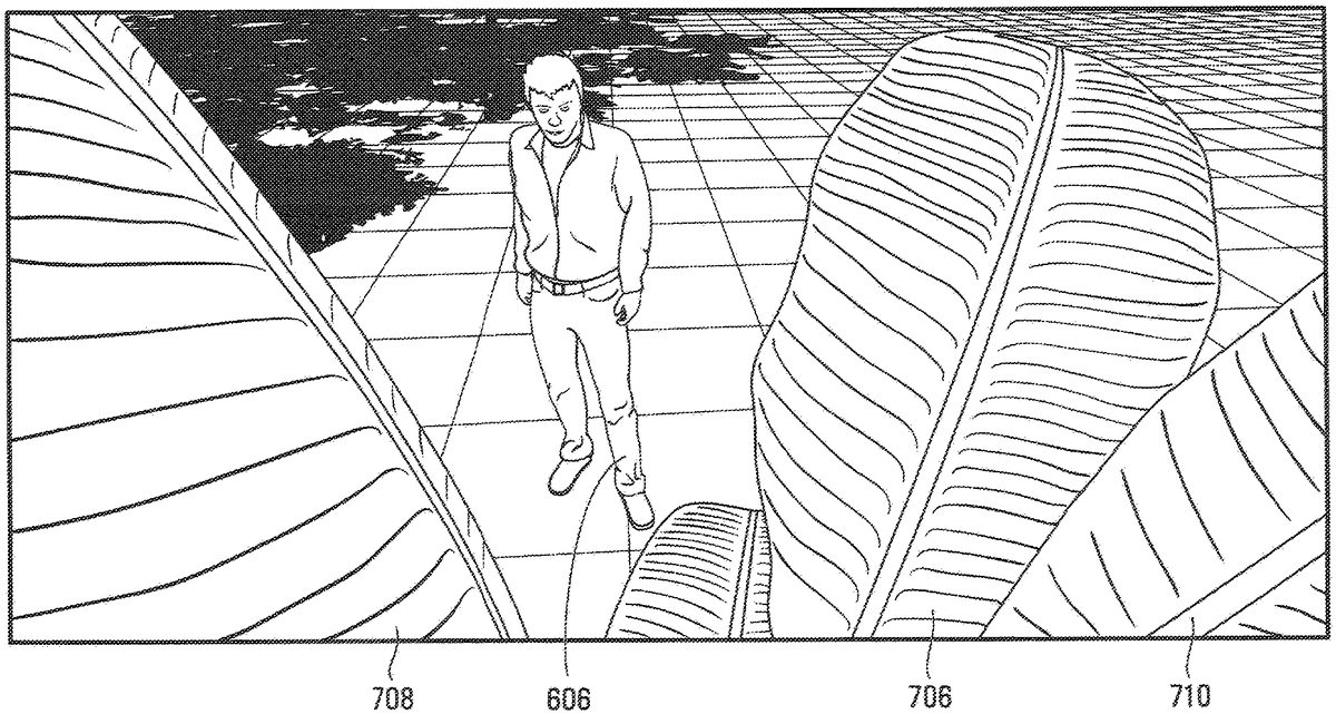
Turning now toFIG. 7, there is shown an example third-person view from the virtual camera602(the virtual camera is not shown inFIG. 7), which includes objects that are visible in the field of view of the virtual camera. In the present example, the visible objects include a floor702, a shadow704and leaves706,708,710. The leaves706,708and710are flexible and resilient, and their natural position is illustrated inFIG. 7. The leaves706,708and710are part of a common plant and thus may be associated with bones that are interconnected to one another, such that movement of each leaf has an impact on the others. The view ofFIG. 7represents the view that would be rendered on-screen without any effect of the camera collision primitive604(not shown inFIG. 7) and does not show the playing character606, which is in a position “behind” leaf706where it is obstructed from view. It is seen that visibility of the playing character606is significantly obstructed by at least one object, including an environment element (in this case leaf706).
According to an embodiment, one or more environment elements (in this case leaves706,708,710) can be bent out of the way as a consequence of a collision between the camera collision primitive604and the collision primitives (not shown inFIG. 7) associated with the leaves706,708,710, as will now be described.
An overview of a rendering process that may be executed by the processing entity (e.g., the processor10) is now presented with reference toFIG. 11. At step1110, the processing entity maintains the virtual environment for the video game. It is recalled that the virtual environment may include the virtual camera602, an object of interest (such as the playing character) and an environment element of which at least a portion is located between the virtual camera and the object of interest (such as leaf706). At step1120, the processing entity produces a sequence of image frames representing evolution of a scene within the video game, e.g., as part of the game rendering processing function24. The scene includes objects from the virtual environment within the field of view of the virtual camera. At step1130, over the course of multiple ones of the image frames, the processing entity renders an appearance of movement (e.g., flexion) of the portion of the environment element in correspondence with movement of the virtual camera602within the virtual environment. Part of the scene that was previously occupied by a portion of the environment element that was moved is replaced with a previously unexposed part of the object of interest. In this way, more of the object of interest is exposed in at least part of the scene that was previously occupied by the portion of the environment element that was moved.
To this end, reference is made toFIG. 8, which shows steps in a process to cause the appearance of movement of an environment element that would otherwise obstruct the view of the playing character from the virtual camera. The process may be encoded in computer readable instructions executed by the processing entity. The process may apply to some or all segments of some or all environment elements in the scene that have associated collision primitives. The process may be executed at each frame, although this is not a requirement and the process may be executed less frequently to save computational resources. It is assumed that the camera collision primitive604has been defined; this may be done in an initialization phase.
At step810, the processing entity detects whether there is a new or ongoing collision between the collision primitive of a particular segment of the environment element and the camera collision primitive. A collision may be considered “new” when the camera collision primitive associated with a moving virtual camera is found to enter into contact with the collision primitive of the particular segment. In some cases, a collision may last a single frame. In other cases, a collision lasts at least several frames and therefore in subsequent frames what was first considered a “new” collision is then considered an “ongoing” collision. It should be appreciated that a collision can be detected as “ongoing” at step810even when the virtual camera has come to a standstill, as there is still contact between the camera collision primitive and the collision primitive of the particular segment.
If a new or ongoing collision is indeed detected at step810, then the process leads to step820where the “contact torque” is determined, namely the computes the force on the collision primitive of the particular segment (and/or the torque about its base point) generated by the collision. A non-limiting technique for performing a computation of the “contact torque” is described later on.
It should be appreciated that when a collision is detected between the camera collision primitive and at least one collision primitive of the environment element, the virtual camera is not itself colliding with that environment element or even with its collision primitive. The environment element may be close enough to the virtual camera so as to obstruct its view, without actually being in contact therewith.
After computation at step820of the contact torque generated by the collision, the process proceeds to step830, where the next position and velocity of the particular segment are calculated according to a set of mathematical equations that depend on, among other things, the contact torque computed at step820. A non-limiting technique for performing this computation is described later on. Basically, the contact torque computed at step820competes with other torques that may be applied about the base point of the segment, resulting in a sum of torques, which then causes movement of the particular segment (unless the sum is zero). An example of a competing torque may come from the inherent resiliency of the environment element, or from gravity.
If no new or ongoing collision was detected at step810, then the process leads to step840, where the processing entity determines whether the particular segment was in motion.
If at step840the processing entity determines that the particular segment is in motion, the processing entity proceeds to step830where, as previously described, the next position and velocity of the particular segment are calculated according to a set of mathematical equations. It should be appreciated that since there is no longer a new or ongoing collision, movement will no longer be due to a contact torque, but rather based on the other factors in the game, including but not limited to exertion of a biasing force to return the particular environment element to its natural position, or a force arising from movement of another segment of the environment element that is connected to the particular segment for which the process is being executed.
If at step840the processing entity determines that the particular segment was not in motion, then the next step is step850, where the position and velocity of the particular segment remain unchanged by this process.
It will be appreciated that equilibrium may ultimately be reached between the camera collision primitive and the collision primitive associated with a particular environment element. At such equilibrium, the sum of the torques is zero. In this regard, consider nowFIG. 9, which illustrates the equilibrium state having been reached between a capsule-like collision primitive904of a corn stalk902and a camera collision primitive906(viewed transversely, from the vantage point of the large end of the capsuloid). It is noted that the collision primitive904is slightly pivoted relative to the bottom part of the illustration, as a result of the collision with the camera collision primitive906. As such, the corn902is rendered as moved/bent. The zero-sum torque arises from the contact torque being counterbalanced by the resiliency of the corn902.
It is also seen inFIG. 9that there is some interpenetration950of the collision primitive904and the camera collision primitive906at equilibrium in this embodiment. In other embodiments, the collision primitive904of the corn902and the camera collision primitive906may be constrained to reach equilibrium without any interpenetration. This would result in the corn902being rendered as even more bent, since its collision primitive904would be pushed away even more by the camera collision primitive906, whose position is closely tied to the position of the virtual camera602as determined by the game program depending on the controls exerted by the user.
Returning now to the example of the leaves706,708,710inFIG. 7, and assuming that each leaf is represented by an individual collision primitive and that the leaves are connected to a common stem or stalk (that is beyond the bottom of the Figure), reference is now made toFIG. 10, which visually demonstrates the effect of the process ofFIG. 8after equilibrium has been reached. In particular, it is seen that leaf706, which had been obstructing the view of the playing character from the virtual camera, is now moved and out of the way, and the previously hidden playing character606is now visible. In particular, the processing entity has caused clearing of the field of view of the virtual camera by rendering an appearance of movement of leaf706.
It will also be observed from comparingFIG. 7toFIG. 10that leaf708has also slightly moved, although in a direction towards the center of the image, i.e., towards the camera collision primitive (though not shown inFIG. 10). This is due to the fact that significant movement of leaf706towards the right provoked slight movement of leaf708towards the right since leaves706and708are connected to the same stalk. The degree to which transfer of motion takes place is dependent on the level of sophistication of the game program. In any event, should there be a significant rightwards force on leaf708due to the game program, the process ofFIG. 8, when executed for the collision primitive of leaf708, would detect a collision with the camera collision primitive and thus would also ensure that leaf708does not, for its own part, end up obstructing the line of sight between the virtual camera and the playing character.
The aforementioned clearing of the field of view of the virtual camera is dynamically ongoing as the virtual camera moves within the virtual environment and new environment elements are moved due to newly detected collisions between their respective collision primitives and the camera collision primitive.
Non-Limiting Algorithm for Computing the Contact Torque
A non-limiting algorithm for executing step830in order to compute the next position and velocity of an environment element further to detection of a collision (between the camera collision primitive and the collision primitive of environment element) is now described. Here, the next position and velocity are considered to be angular measurements, as the collision primitive of the environment element pivots about a base point, although this need not be the case in every embodiment. Generally speaking, the environment element may be modeled as a damped spring with an initial natural position and a resilience defined by a spring constant, but again, this need not be the case in every embodiment.
With reference toFIG. 8, a first step is to find the two closest points in 3D on the segments in the colliding primitives, shown as P1for the collision primitive of the flexible element (in this case, a branch) and P2for the camera collision primitive. Once the two closest points are found, one proceeds to find the point Pb, which is the base point around which the branch revolves. In the present non-limiting model, the branch only rotates, and does not translate or stretch, although this more complex behaviour may be accounted for in other embodiments. Parent and child branches will also affect each other in a complex way, which is taken care of by the game program.
The collision of the camera collision primitive with the collision primitive of a particular branch will generate a rotation or pivoting of that branch, as now described. First, the vector d is defined as the vector going from P2to P1:
{right arrow over (d)}=P1−P2
And its direction (unit vector) is described as follows:
d^=d|d→|
One may use a formula for the force generated by the collision between the camera collision primitive and the collision primitive associated with the branch, such as:
Fc→=d^·(1-|d→|r)·m(eq.1)
where r=r1+r2, in which r2is the radius of the camera collision primitive colliding with the branch (for a capsuloid with 2-radii capsule, r2it is the radius at the collision point) and r1is the radius of the capsule of the branch. These parameters may be inputs to the user. The fact that the term in parentheses is unity minus a ratio ensures that there is a maximum force when the capsule/capsuloid are the most interlaced and the length of d (the minimum distance between the colliding primitives) is 0.
The factor m may be tweaked with multiple values:
m=(f+fv)·μ·p
where f is the main factor and is entered by a user for each environment element that has flexible segments. Also, p is a multiplier entered by the user, and depends on the camera collision primitive. The factor μ is another multiplier so that branches react differently when its collision primitive collides with characters or with the camera collision primitive. Finally, the factor fv is a velocity effect multiplier, so if a character runs into the branch, the plants will move more than if a character moves slowly into it:
fv=v·f·s
where v is the norm of the velocity of the virtual camera (or character running into the branch) and s is a speed effect multiplier (which may be user definable).
As such, Eq. 1 above computes the force that the branch receives, each frame, from colliding geometries between its collision primitive and (in this case) the camera collision primitive. This force is applied continuously, and lasts for as long as the primitives are interpenetrating. When they are barely in contact, the force will be very small, and it will increase with the interpenetration, leading to smooth movements. Note that the geometries might still be interpenetrating at the rest/equilibrium position.
The force computed above is used to generate the contact torque, since the branch rotates about its base point. The lever used for the contact torque is:
{right arrow over (L)}=P1−Pb
Thus, the contact torque generated on the branch is:
{right arrow over (Tc)}={right arrow over (L)}×{right arrow over (Fc)} (eq. 2)
Non-Limiting Algorithm for Computing the Next Position and Velocity
Branches and certain other flexible environment elements may be simulated as damped springs. During the same frame where the contact torque is calculated, the spring force model is simulated and resulting torques are added to the contact torque. It is noted that the branch uses torques, thus the quantities are angular in nature.
In the simulation, the damping force opposes the velocity of the branch and is calculated as:
{right arrow over (Td)}=−ω·k·{right arrow over (V)}(eq. 3)
where k is a constant that the user can enter, and it is referred to as the “damping factor”. ω is the natural frequency of the system and it also may be user-definable. V denotes the angular velocity.
Added to the damping force, a spring force opposes the displacement of the branch and is calculated as:
{right arrow over (Ts)}=−ω2·{right arrow over (X)}(eq. 4)
in which ω (also used in Eq. 3) is the natural frequency of the system. Note that X is the angular position of the branch.
The next angular position can be found knowing the current position. The following equations of motion can be used:
Xt+Δt→=Xt→+dX→dt·Δt+12·d2X→dt2·(Δt)2
where Δt is one frame duration, and, by definition velocity is the derivative of position
V→=dX→dt
and acceleration is the second order derivative of the position
a→=d2X→dt2,
leading to the following equation:
Xt+Δt→=Xt→+Vt→·Δt+a→2·(Δt)2(eq.5)
To be able to use Eq. 5, one still needs V, the velocity, which changes every frame and a, the acceleration. For the velocity, one can use a first degree approximation, still using an equation of motion:
Vt+Δt→=Vt→+dV→dt·Δt
It is known that acceleration is the derivative of velocity:
a→=dV→dt.
This leads to Eq. 6:
{right arrow over (Vt+Δt)}={right arrow over (Vt)}+{right arrow over (α)}·Δt(eq. 6)
In both Eq. 5 and Eq. 6, one needs to determine the value of the acceleration. It is known from Newton that {right arrow over (F)}=m·{right arrow over (α)}. For convenience, since there are many parameters, m=1 is used. Since torques are being used, the acceleration is the sum of all torques:
{right arrow over (α)}={right arrow over (Tc)}+{right arrow over (Td)}+{right arrow over (Ts)}={right arrow over (Ttot)}
Thus, the final equations to calculate the next angular position and velocity for the frame are the following:
Xt+Δt→=Xt→+Vt→·Δt+12·Ttot→·(Δt)2(eq.7)Vt+Δt→=Vt→-Ttot→·Δt(eq.8)
It should further be appreciated that under the damped spring model, the environment element has a tendency (defined by the spring constant) to want to return to its natural position. The natural position may be reassumed when the virtual camera moves away such that there is no more contact between the collision primitive of the environment element and the camera collision primitive.
In an alternative embodiment, the environment element may be allowed to return to its natural position even when there is still contact between the collision primitive of the environment element and the camera collision primitive. This can be arranged to happen when the virtual camera is immobile or has a velocity less than a certain threshold. That is to say, the camera collision primitive ceases to have a field-of-view clearing effect at low speeds. Thus, as a result of the return of the environment element to its natural position, it may re-obstruct visibility of the playing character from the virtual camera (as inFIG. 7). While this may detrimentally prevent the player from fully seeing the playing character, it may be perceived as added realism for certain flexible environment elements. For example, consider a bead curtain with strings of beads hanging vertically from a horizontal beam at a certain distance between the virtual camera and the playing character. The strings of beads have a tendency to want to return to a straight vertical position under gravity. Although the player may appreciate that the bead curtain will be moved away from the field of view of the virtual camera during an active scene so that the playing character can be more clearly seen (i.e., rendered), the player may equally appreciate the realism that arises from the bead curtain reverting to a vertical orientation when the scene becomes static. This may be perceived as more realistic compared to the bead curtain espousing a phantom shape corresponding to the camera collision primitive.
In still other embodiments, the environment element may be allowed to return to its natural position as soon as the playing character is removed from the theoretical field of view of the virtual camera (i.e., the playing character is no longer visible irrespective of any obstruction in front of the virtual camera).
As such, and with reference toFIG. 12, there has been provided a process that includes a step1210of maintaining a virtual environment for a video game. The virtual environment includes a virtual camera, an object of interest and an environment element of which at least a portion is located between the virtual camera and the object of interest. The method includes a step1220, at which a sequence of image frames is produced, representing evolution of a scene within the video game. The scene includes objects from the virtual environment within a field of view of the virtual camera. The process further includes a step1230, which includes rendering an appearance of movement of the portion of the environment element to expose more of the object of interest in at least part of the scene previously occupied by the portion of the environment element that was moved, as illustrated, for example, in the change visible between the on-screen renderings ofFIGS. 7 and 10. This may be done over the course of multiple ones of the image frames. It is noted that although the virtual camera itself is not visible, effects are felt through movements of, and collisions involving, its camera collision primitive.
Those skilled in the art should appreciate that further realizations and variants are possible, and that certain embodiments may omit certain elements described above, all within the scope of the invention, which is defined by the claims appended hereto.
Claims
- A non-transitory computer-readable medium storing instructions for execution by a processing entity, wherein execution of the instructions by a processing entity implements a method that comprises: producing image frames representing evolution of a scene in a field of view of a virtual camera in a virtual environment, the scene including an environment element and a playing character controlled by a player of a video game;rendering in the image frames an appearance of movement of the environment element in correspondence with movement of the virtual camera within the virtual environment;over the course of multiple ones of the image frames, replacing at least part of the scene previously occupied by a portion of the environment element that was moved with a previously unexposed part of the playing character;detecting an occurrence of a collision between a camera collision primitive and at least one collision primitive of the environment element, wherein said rendering an appearance of movement of the environment element is carried out responsive to said detecting, wherein after the collision, the movement of the environment element reaches an equilibrium at which the camera collision primitive and the at least one collision primitive of the environment element interpenetrate;wherein the camera collision primitive is a virtual 3D shape extending at least partly between the virtual camera and the playing character, and wherein the at least one collision primitive of the environment element at least partly surrounds the environment element.
- The non-transitory computer-readable medium defined in claim 1 , wherein neither the camera collision primitive nor the collision primitive of the environment element are rendered in the image frames.
- The non-transitory computer-readable medium defined in claim 1 , wherein the 3D shape is a capsuloid with identical or different radii of curvature.
- The non-transitory computer-readable medium defined in claim 1 , wherein the 3D shape has an elongate shape with a first end and a second end, the first end being proximate the virtual camera, the second end being located between the virtual camera and the playing character.
- The non-transitory computer-readable medium defined in claim 4 , wherein 3D shape tapers towards the first end.
- The non-transitory computer-readable medium defined in claim 4 , wherein 3D shape has a length dimension between the first end and the second end, and has a cross-section transverse to the length dimension that is smaller, on average, within the half of the 3D shape nearer the virtual camera than within the half of the 3D shape nearer the playing character.
- The non-transitory computer-readable medium defined in claim 6 , wherein the length of the camera collision primitive is a variable defined at runtime.
- The non-transitory computer-readable medium defined in claim 4 , wherein 3D shape expands in size outwards from the virtual camera towards the playing character.
- The non-transitory computer-readable medium defined in claim 4 , wherein the second end is located approximately half way between the virtual camera and the playing character.
- The non-transitory computer-readable medium defined in claim 4 , wherein the second end is located no more than three quarters of the way between the virtual camera and the playing character.
- The non-transitory computer-readable medium defined in claim 1 , wherein the at least one collision primitive of the environment element includes a virtual 3D shape surrounding the environment element.
- The non-transitory computer-readable medium defined in claim 11 , wherein at least one of the at least one collision primitive of the environment element includes a capsule.
- The non-transitory computer-readable medium defined in claim 12 , wherein movement of the environment element comprises flexion of the capsule about a base point.
- The non-transitory computer-readable medium defined in claim 13 , wherein the base point is not within the field of view of the virtual camera.
- The non-transitory computer-readable medium defined in claim 1 , wherein when the environment element is modeled as a bone, the at least one collision primitive of the environment element includes a virtual 3D shape surrounding the bone.
- The non-transitory computer-readable medium defined in claim 1 , wherein when the environment element is modeled as a plurality of interconnected bones, the at least one collision primitive of the environment element includes an arrangement of virtual 3D shapes surrounding respective ones of the bones.
- The non-transitory computer-readable medium defined in claim 1 , wherein a degree of movement of the environment element corresponds to a torque applied to the collision primitive of the environment element.
- The non-transitory computer-readable medium defined in claim 17 , wherein the method further comprises computing the applied torque.
- The non-transitory computer-readable medium defined in claim 18 , wherein computing the applied torque comprises computing a function of a collision torque produced by the collision and a resilience associated with the environment element.
- The non-transitory computer-readable medium defined in claim 1 , wherein before movement of the environment element, the environment element occupied a natural position, and wherein the method further comprises rendering the environment element as returning to its natural position after additional movement of the virtual camera.
- The non-transitory computer-readable medium defined in claim 1 , wherein before movement of the environment element, the portion of the environment element that was moved occupied a natural position, and wherein the method further comprises rendering the portion of the environment element as returning to its natural position after detecting that there is no longer a collision between the camera collision primitive and the collision primitive of the portion of the environment element.
- The non-transitory computer-readable medium defined in claim 1 , wherein when a collision is detected between the camera collision primitive and at least one collision primitive of the environment element, the virtual camera is not in a collision with the environment element.
- The non-transitory computer-readable medium defined in claim 1 , wherein movement of the virtual camera within the virtual environment includes any of a translation of the virtual camera within the virtual environment and a change in orientation of the virtual camera relative to a fixed location within the virtual environment.
- The non-transitory computer-readable medium defined in claim 1 , wherein movement of the virtual camera is a result of input received from a player of the video game and processed by the processing entity.
- The non-transitory computer-readable medium defined in claim 1 , wherein the environment element is any of a plant, a reed, a branch, a leaf, a vine, algae, a flag, a bead curtain, a vertical blind and a corpse.
- The non-transitory computer-readable medium defined in claim 1 , wherein the camera collision primitive ends at a point that is 50% to 90% of the distance between the virtual camera and the playing character.
- A method comprising: producing image frames representing evolution of a scene in a field of view of a virtual camera in a virtual environment, the scene including an environment element and a playing character controlled by a player of a video game;rendering in the image frames an appearance of movement of the environment element in correspondence with movement of the virtual camera within the virtual environment;over the course of multiple ones of the image frames, replacing at least part of the scene previously occupied by a portion of the environment element that was moved with a previously unexposed part of the playing character;detecting an occurrence of a collision between a camera collision primitive and at least one collision primitive of the environment element, wherein said rendering an appearance of movement of the environment element is carried out responsive to said detecting, wherein after the collision, the movement of the environment element reaches an equilibrium at which the camera collision primitive and the at least one collision primitive of the environment element interpenetrate;wherein the camera collision primitive is a virtual 3D shape extending at least partly between the virtual camera and the playing character, and wherein the at least one collision primitive of the environment element at least partly surrounds the environment element.
- A non-transitory computer-readable medium storing instructions for execution by a processing entity, wherein execution of the instructions by a processing entity implements a method that comprises: maintaining a virtual environment for a video game, the virtual environment including a virtual camera, a playing character controlled by a player of a video game and an environment element of which at least a portion is located between the virtual camera and the playing character;producing a sequence of image frames representing evolution of a scene within the video game, the scene including objects from the virtual environment within a field of view between the virtual camera and the playing character;over the course of multiple ones of the image frames, rendering an appearance of movement of the portion of the environment element to expose more of the playing character in at least part of the scene previously occupied by the portion of the environment element that was moved;detecting an occurrence of a collision between a camera collision primitive and at least one collision primitive of the environment element, wherein said rendering an appearance of movement of the environment element is carried out responsive to said detecting, wherein after the collision, the movement of the environment element reaches an equilibrium at which the camera collision primitive and the at least one collision primitive of the environment element interpenetrate;wherein the camera collision primitive is a virtual 3D shape extending at least partly between the virtual camera and the playing character, and wherein the at least one collision primitive of the environment element at least partly surrounds the environment element.
- A method comprising: maintaining a virtual environment for a video game, the virtual environment including a virtual camera, a playing character controlled by a player of a video game and an environment element of which at least a portion is located between the virtual camera and the playing character;producing a sequence of image frames representing evolution of a scene within the video game, the scene including objects from the virtual environment within a field of view between the virtual camera and the playing character;over the course of multiple ones of the image frames, rendering an appearance of movement of the portion of the environment element to expose more of the playing character in at least part of the scene previously occupied by the portion of the environment element that was moved;detecting an occurrence of a collision between a camera collision primitive and at least one collision primitive of the environment element, wherein said rendering an appearance of movement of the environment element is carried out responsive to said detecting, wherein after the collision, the movement of the environment element reaches an equilibrium at which the camera collision primitive and the at least one collision primitive of the environment element interpenetrate;wherein the camera collision primitive is a virtual 3D shape extending at least partly between the virtual camera and the playing character, and wherein the at least one collision primitive of the environment element at least partly surrounds the environment element.
Disclaimer: Data collected from the USPTO and may be malformed, incomplete, and/or otherwise inaccurate.