U.S. Pat. No. 10,744,405
VIDEO GAME INCORPORATING SAFE LIVE-ACTION COMBAT
Issue DateSeptember 24, 2018
Illustrative Figure
Abstract
Video games can be improved upon by combining traditional gameplay mechanics (e.g., a player's use of a controller) and live-action combat elements that may be measured and scored. For example, a player may fire projectiles at a target when prompted by a game, may have to dodge projectiles fired at the player as part of the game, may have to traverse the room to touch or move an object, and/or may have to strike a dummy or other object as instructed by the game. Such live-action combat aspects may be incorporated into a video game having otherwise traditional gameplay mechanics.
Description
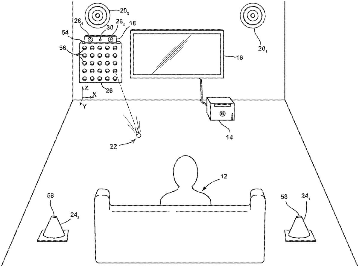
DETAILED DESCRIPTION Referring to the drawings, wherein like reference numerals refer to the same or similar features in the various views,FIG. 1is a diagrammatic perspective view of a portion of a system10for a video game incorporating safe live-action combat that may be played by a user12. The system10may include a video game system14, a display16, a camera18, one or more projectile targets20(with two such projectile targets201,202shown), one or more projectiles22, one or more movement targets24(with two such movement targets241,242shown), and an automated projectile apparatus26. The system10may be configured to operate a game including elements of display-centric gameplay and elements of live-action combat. An exemplary embodiment of the system10and its various components will first be described, followed by a description of exemplary gameplay elements that may be provided according to the present disclosure. System Overview. The system10(and other devices and apparatus discussed in this disclosure) may be used to provide one or more video games. Such video games may include, for example, elements of traditional video games (e.g., directing action on the display with a handheld controller or similar device) and elements of live-action combat. Such video games may be provided in a private environment (e.g., a home) and/or in a public environment (e.g., an arcade, a restaurant). This disclosure may generically refer to “a game” or “the game”; such references should be understood to refer to any game which includes devices or gameplay elements illustrated in, described in, referenced in, and/or enabled by this disclosure. Accordingly, references to “a game” or “the game” should be understood to be for ease of description only, and do not specify a particular game unless so explicitly stated. The video game system14may be or may include a suitable presently-available or hereafter-developed video game system configured for use with a wide variety of games, such ...
DETAILED DESCRIPTION
Referring to the drawings, wherein like reference numerals refer to the same or similar features in the various views,FIG. 1is a diagrammatic perspective view of a portion of a system10for a video game incorporating safe live-action combat that may be played by a user12. The system10may include a video game system14, a display16, a camera18, one or more projectile targets20(with two such projectile targets201,202shown), one or more projectiles22, one or more movement targets24(with two such movement targets241,242shown), and an automated projectile apparatus26. The system10may be configured to operate a game including elements of display-centric gameplay and elements of live-action combat. An exemplary embodiment of the system10and its various components will first be described, followed by a description of exemplary gameplay elements that may be provided according to the present disclosure.
System Overview.
The system10(and other devices and apparatus discussed in this disclosure) may be used to provide one or more video games. Such video games may include, for example, elements of traditional video games (e.g., directing action on the display with a handheld controller or similar device) and elements of live-action combat. Such video games may be provided in a private environment (e.g., a home) and/or in a public environment (e.g., an arcade, a restaurant). This disclosure may generically refer to “a game” or “the game”; such references should be understood to refer to any game which includes devices or gameplay elements illustrated in, described in, referenced in, and/or enabled by this disclosure. Accordingly, references to “a game” or “the game” should be understood to be for ease of description only, and do not specify a particular game unless so explicitly stated.
The video game system14may be or may include a suitable presently-available or hereafter-developed video game system configured for use with a wide variety of games, such as a MICROSOFT XBOX 360, MICROSOFT XBOX ONE, SONY PLAYSTATION 3, SONY PLAYSTATION 4, NINTENDO WII, or another video game system. Additionally or alternatively, the video game system14may be or may include a video game system designed for a more limited use (e.g., a single game or small set of games), including use with a video game incorporating live-action combat as illustrated and described herein. Additionally or alternatively, the video game system14may be or may include a suitable general purpose computer configured for video games and for other applications.
The display16may be or may include any type of suitable display, including a liquid-crystal display (LCD), light-emitting diode (LED) display, organic LED (OLED) display cathode-ray tube (CRT) display, and/or another type of display currently known or hereafter developed. A single display16may be used, in an embodiment, or multiple displays16may be used, in another embodiment.
The display16may incorporate touch capabilities, in an embodiment. Many different “touch screens” technologies may find use with this disclosure, including resistive touch screens, surface acoustic wave (SAW) touch screen, capacitive touch screens, projected capacitance-type (PCT) touch screens, strain gauge touch screens, optical imaging touch screens, dispersive signal technology (DST) touch screens, acoustic pulse recognition (APR) touch screens, and/or other touch screen types.
The camera18may be or may include one or more image detection devices configured to detect an image of or otherwise track one or more users and/or one or more additional objects. The camera18may be disposed on or integrated into the automated projectile apparatus54or the display16, or may be or may include devices and components physically separate from the other devices and components in the system10. The camera18may capture images according to light from any portion of the electromagnetic spectrum, in embodiments. For example, the camera18may be configured to image one or both of visible light and infrared light, in an embodiment. The camera18may comprise multiple lenses and/or imaging capture devices, in an embodiment. For example, the camera may comprise a first image capture device281, a second image capture device282, and a range device30. One or both of the first image capture device281and the second image capture device282may capture images in the visible light spectrum, and one or both of the first image capture device281and the second image capture device282may capture images in the infrared light spectrum. The range device30may determine the distance from one or more objects to the camera18. For example, the range device30may project and receive one or more lasers to determine distances between the camera18and one or more users and/or one or more other objects.
The camera18may be in electronic communication with the video game system14, in an embodiment. As a result, a video game or other application executing on the video game system14may have access to image data, distance data, and/or other data from the camera18. Accordingly, the video game system14may be able to determine the location of the user12, movements of the user12, and the location and movement of other objects, such as projectiles22and/or targets20,24, for example.
The system10may be configured to enable video game play that includes propelling of physical projectiles22as part of the game. For example, a game according to the present disclosure may include gameplay elements of a user12controlling action on the display16and more active gameplay elements of a user12propelling physical projectiles22at one or more targets (e.g., projectile targets20), manually striking one or more objects, and/or dodging one or more physical projectiles22propelled at the user. Accordingly, the system10may include devices and programming directed to such live-action combat gameplay elements, in an embodiment.
The system10may include one or more physical projectiles22. Projectiles22may be propelled by the user12, in an embodiment, and/or at the user12, in an embodiment, both of which are described in further detail below. Projectiles22may include physical projectiles such as darts, balls, disks, and the like. Physical projectiles22may have a tangible, consistent form, in an embodiment (i.e., distinguishing physical projectiles from water or a laser, for example). One or more of the projectiles22used in the system may comprise one or more materials including foam, rubber, plastic, and other materials including, but not limited to, materials that cause little or no damage when making contact with other objects.
One or more of the projectiles22may include features for tracking the projectile22. For example, a projectile22may include a visible tag, such as a visible light reflector, infrared reflector/tag, or other visible tag. Additionally or alternatively, a projectile22may include a radio frequency identification (RFID) chip, a global positioning system (GPS) antenna, a digital gyroscope, and/or another chip, antenna, or sensor that may be used to determine the position and/or movement of the projectile22. Additionally or alternatively, a projectile22may include a pressure sensor, gyroscope chip, optical sensor, capacitive surface or element, and/or another chip or sensor that may be used to determine an impact (e.g., force thereof) of the projectile22with an object. Such features for tracking the projectile22may be used, for example only and as described further below, for tracking a projectile22to, e.g., determine the accuracy and distance travelled of a projectile propelled by a user12or at a user12, the response time of a user12to fire a projectile following a prompt, etc.
In an embodiment, a projectile22may be in electronic communication with the video game system14, with a projectile target20, with a camera18, etc. The projectile22may transmit data from a sensor, antenna, chip, etc. that may be used for tracking the projectile22.
FIG. 2is an isometric view of an exemplary embodiment of a dart-style projectile22athat may be used in the system10. The projectile22amay include a foam body32, a rubber head34disposed on the anterior end36of the body32(i.e., where “anterior” refers to the direction in which the projectile22ais intended to be propelled), and a tag/sensor/antenna38on an anterior surface40of the head34. The tag/sensor/antenna38may be or may include, for example, a visible light reflector, an infrared light reflector, and/or another type of tag. The tag/sensor/antenna38may additionally or alternatively be or include another type of sensor or device to enable tracking the projectile22a. Furthermore, in addition to or instead of a tag/sensor/antenna38on a surface of the projectile22a, a tag/sensor/antenna38may be embedded in the projectile22a.
Referring again toFIG. 1, the projectile targets20may be provided as targets at which the user may propel projectiles22. A single projectile target20may be provided in the system10, in an embodiment. In another embodiment, two or more projectile targets20may be provided.
A projectile target20may comprise a shape, size, and materials suitable for a single strike by a projectile22, or for repeated strikes by one or more projectiles22. For example, but without limitation, a projectile target20may comprise plastic, rubber, foam, metal, and/or another material, and may have a size on the order of a few inches up to a few feet. In an embodiment, as illustrated inFIG. 1, a projectile target20may have a “bullseye” configuration of multiple concentric rings. Additionally or alternatively, a projectile target20may include a portion having some other shape and/or appearance.
A projectile target20may include features for tracking a projectile22fired at the projectile target20. For example, a projectile target20may include one or more pressure sensors, one or more optical sensors, one or more lasers, and/or one or more other sensors for detecting an impact or presence of a projectile22or other object, in an embodiment. Additionally or alternatively, a projectile target20may include a sensor configured to detect a feature of a projectile22. For example, a projectile target20may include an RFID reader, a capacitive touch surface, and/or one or more readers, sensors, or other devices configured to operate in conjunction with a tracking feature of a projectile22.
Each projectile target20may be in electronic communication with the video game system14, with the camera18, with the automated projectile apparatus26, and/or with another portion of the system10. As a result, a projectile target20may track one or more projectiles22and report tracking information to another device in the system10such as, but not limited to, the video game system14, the automated projectile apparatus26, etc.
In an embodiment, multiple devices in the system10may be involved in tracking projectiles22. For example, the camera18may be configured to capture images of projectiles22and/or one or more portions of projectiles22, such as a visible light reflector and/or infrared reflector. Additionally or alternatively, the video game system14, a projectile target20, and/or other device in the system10may receive other data related to tracking a projectile22. For example, a projectile22may transmit GPS data, gyroscope data, pressure sensor data, optical sensor data, and/or other data derived from a sensor or device on or in the projectile22, and the video game system14, projectile target20, and/or other device in the system10may receive and use such data (e.g., in conjunction with other data) to track the projectile22.
Projectile tracking information may be used, in an embodiment and for example only, to determine the accuracy of a projectile22with respect to a projectile target20, to determine the speed with which a user12propels a projectile22responsive to a prompt (i.e., the user's reaction time), to determine the distance travelled by a projectile22, and/or to determine if a projectile22impacts a user12. Additionally or alternatively, projectile tracking information may be used to assist a user12in finding projectiles22that have been propelled in the course of game play.
As noted above and below, a user12may propel one or more projectiles22at one or more projectile targets20, in an embodiment. In an embodiment, a user12may propel a projectile22under his or her own force (e.g., throw or kick a projectile). Additionally or alternatively, a user12may propel a projectile22from a “gun” or other projectile discharge apparatus. Portions of this disclosure will refer to an embodiment in which a user12discharges (i.e., “fires”) projectiles22from an apparatus (which may be referred to as a “projectile gun”), but it should be understood that such description is exemplary only and not limiting except as explicitly set forth in the claims.
FIG. 3is an isometric view of an exemplary embodiment of a first hand-worn projectile discharge apparatus42afor dart-style projectiles22a. The first hand-worn projectile discharge apparatus42amay be similar to that described in U.S. Pat. No. 5,359,985 (“the '985 patent”), which is hereby incorporated by reference in its entirety. Though a more thorough description of an embodiment of the projectile discharge apparatus42ais given in the '985 patent, a brief description is given below.
The hand-worn projectile discharge apparatus42amay have a generally ribbed and substantially planar first portion44and opposed and downwardly extending side portions46which cooperate with the planar portion44to form a generally cup-shaped recess48which is adapted to overlay the back side of a user's hand, opposite the user's palm. The apparatus42amay include one or more projectile reception chambers50; the embodiment illustrated inFIG. 3includes five projectile reception chambers501,502,503,504,505which may be configured to dischargedly receive projectiles22a. The projectile discharge apparatus42may enable the user to discharge a projectile22afrom one of the chambers501,502,503,504,505by pulling a trigger with a finger521,522,523,524,525that is associated with that chamber50. That is, the projectile discharge apparatus42amay include a first trigger for the user's thumb521that, when pulled, causes a projectile to be discharged from a first projectile reception chamber501, a second trigger for the user's index finger522that, when pulled, causes a projectile to be discharged from a second projectile reception chamber502, and so on.
The hand-worn projectile discharge apparatus42amay advantageously enable a user to wear the projectile discharge apparatus42awhile also holding and manipulating a handheld controller for a video game, in an embodiment. Such flexibility may aid in a video game incorporating a segment in which a user directs action on a display with the handheld controller and a segment in which the user propels projectiles at one or more targets, as described herein. Alternatively, in an embodiment, the projectile discharge apparatus42amay be configured to be held, rather than worn, by the user.
Referring toFIGS. 1-3, the projectile discharge apparatus42amay be used by the user12to fire one or more projectiles22(e.g., such as one or more of the projectiles22aofFIGS. 2 and 3) at, for example, the projectile targets20. Of course, additional or alternative projectile discharge apparatuses42amay be used, and additional or alternative projectiles22may be used. That is, the projectile22aofFIG. 2(and the features thereof) and the projectile discharge apparatus42aofFIG. 3(and the features thereof) are exemplary only, and are not limiting except as explicitly set forth in the claims.
Referring again toFIG. 1, the automated projectile apparatus26may be provided in the system10to fire projectiles22at the user12, in an embodiment. The automated projectile apparatus26may include a housing54having a plurality of projectile reception chambers56that are each configured to fire one or more projectiles22. The projectile(s)22discharged by the automatic projectile apparatus26may be the same type of projectiles22fired by the user12at the projectile targets20, in an embodiment, so that a user12may interchangeably use the same projectiles22in a projectile discharge apparatus42a(seeFIG. 3) operated by the user12as are fired by the automatic projectile apparatus26.
The automated projectile apparatus26may be configured to hang on a wall, in an embodiment. That is, the housing54may include one or more support structures, such as brackets, for coupling with the wall through one or more screws, nails, picture wires, etc. Additionally or alternatively, the automated projectile apparatus26may be configured to rest on the floor and/or another surface, and/or be supported by a stand.
The automated projectile apparatus26may be in electronic communication with one or more of the video game system14, the camera18, the projectile targets20, one or more devices intended to held by, worn by, or coupled to a user (e.g., a controller, helmet, etc.) and other devices in the system, in an embodiment. The automatic projectile apparatus26may operate under the control of the video game system14, in an embodiment. For example, the video game system14may analyze the output of the camera18to aim the automated projectile apparatus26at the user and may command the automatic projectile apparatus26to discharge one or more projectiles22at a user12.
The automated projectile apparatus26may additionally include one or more components to assist in aiming the automated projectile apparatus26, in an embodiment. For example, the housing54of the automated projectile apparatus may be mechanically coupled with one or more hydraulic actuators, linear encoder motors, rotary encoder motors, and the like to aim the entire housing54(and correspondingly aim the projectile reception chambers56) in the X-direction and the Z-direction (seeFIG. 1), where the X-direction is lateral, generally parallel to the floor, and the Z-direction is vertical, generally parallel to the wall. The automated projectile apparatus26may additionally or alternatively be configured for aiming in the Y-direction, in an embodiment. Additionally or alternatively, one or more of the projectile reception chambers56may be configured for aiming independent of one or more of the other projectile reception chambers56. For example, the housing54may comprise two, three, four, five, or more rows or columns, in which each row or column is configured to be aimed independent of the other rows or columns in at least one spatial dimension. For example, in an embodiment, the automated projectile apparatus26may include five rows of projectile reception chambers56. The rows may be configured for independent aiming in the X-direction (e.g., through separate hydraulic actuators, linear encoders, rotary encoders, and the like), but for common aiming in the Z-direction.
The automated projectile apparatus26, and gameplay associated with the automated projectile apparatus26, may include various features for varying gameplay, in embodiments. For example, the automated projectile apparatus may include a plurality of projectile propulsion speeds. In a further example, a user may be given a warning in advance of a projectile being fired from the automated projectile apparatus (e.g., on the display16), and the amount of time between the warning and the projectile being fired may vary.
With continued reference toFIG. 1, one or more movement targets24(with two such movement targets241,242shown) may be provided as objects to which a user must move, for example, when prompted by a video game. A movement target24may be or may include any appropriate shape, size, and physical configuration. In an embodiment, a movement target24may simply be an object that is proximate a user playing a video game according to the present disclosure.
The movement target24may include one or more buttons, switches, surfaces, etc. that a user may contact. Such buttons, switches, surfaces, etc. may be coupled to or may include pressure sensors, touch sensors, and/or other types of sensors for detecting a touch or impact from a user. For example, a button may be provided on the top58of a movement target24.
A movement target24may be in electronic communication with one or more of the video game system14, the camera18, the automated projectile apparatus26, and other devices in the system10. The movement target24may transmit a signal to indicate that a user12has made contact with the movement target24. For example, the movement target24may transmit a signal to the video game system14to indicate that a user12has touched the movement target24, responsive to which the video game system14may provide the user feedback regarding the contact (e.g., the speed with which the user12made contact, measured as the time from when a prompt was given to when the user contacts the movement target24, for example) and/or advance to another segment of the game.
In addition to the devices and systems illustrated inFIG. 1, the system10may include additional and/or alternative devices and systems for use in gameplay. For example, the system10may include one or more of a user-manipulated controller, a user-manipulated projectile propelling apparatus, a helmet, a push-up counter, a jump-rope counter, and/or other devices and components.
In an embodiment, the system10may include a handheld controller for use by the user.FIG. 4is a front view of an exemplary embodiment of a handheld controller60that may be used in the system. The handheld controller60may be used by a user, for example, to direct action of a game on the display. The controller60may function substantially similarly to known handheld controllers, in an embodiment, in terms of its capabilities for commanding action on a display.
The controller60may include one or more elements for directional control, in an embodiment. For example, as illustrated inFIG. 4, the controller may include one or more joysticks62(two such joysticks621,622are illustrated) and one or more directional pads64. The controller may further include one or more buttons66, switches, levers, and other elements allowing the user to provide input for a game. The controller60may be configured for handheld operation by a user, in an embodiment. Additionally or alternatively, the controller60may be configured to be supported by the floor, a table, a wall, a supporting structure, etc.
The controller60may include one or more tags/sensors/antennas (e.g., similar to or the same as the one or more tags/sensors/antennas that may be included on the projectile22aillustrated inFIG. 2). The one or more tags may be provided for the controller60to be more effectively tracked by the system10(e.g., imaged by the camera18) (seeFIG. 1). For example, referring toFIGS. 1 and 4, the camera18may be configured to capture images in the infrared spectrum (e.g., among other things and spectra), and the controller60may include one or more infrared reflectors. The video game system14may thus use the infrared images captured by the camera18to determine the location of the controller60and command the automated projectile apparatus26to discharge a projectile22towards the controller60(i.e., under the assumption that a user12is holding or otherwise manipulating or near the controller60).
The controller60may be in electronic communication with one or more of the video game system14, the camera18, the automated projectile apparatus26, and/or another device or component in the system10. The controller60may transmit, for example and without limitation, commands for, e.g., controlling display-centric gameplay and/or data for tracking the controller60.
The system10may further include a helmet configured to be worn by the user.FIG. 5is an isometric view of an exemplary first embodiment of such a helmet70a. In an embodiment, the helmet70amay include a crown portion72aconfigured to fit on or over the top of the user's head, a facial protection portion74aconfigured to partially or completely shield the user's face, and one or more tags/sensors/antennas38.
The crown portion72aof the helmet70amay comprise any size, shape, and materials appropriate for comfortably being worn on the user's head. The crown portion72amay be relatively solid, as illustrated inFIG. 5, or may have one or more vents, holes, or other discontinuities. In an embodiment, the crown portion72aof the helmet70amay comprise a simple wire frame or other relatively light structure suitable for supporting one or more tags/sensors/antennas38and/or the facial protection portion74a. In an embodiment, the crown portion72amay comprise a strap for supporting one or more tags/sensors/antennas38and/or the facial protection portion (i.e., the helmet70amay be or may resemble goggles or other eyewear).
The facial protection portion74aof the helmet70amay be provided to shield the user from projectiles discharged toward the user. Accordingly, the facial protection portion74amay comprise a visor, a cage, and/or any other appropriate structure. The facial protection portion74amay be entirely or mostly translucent or transparent, in an embodiment, so as to minimize the degree to which the facial protection portion74aimpedes user's vision.
Like the controller60ofFIG. 4and the projectile22aofFIG. 2, one or more tags/sensors/antennas38may be provided on the helmet70afor the helmet70ato be more effectively tracked by the system10(e.g., imaged by the camera18) (seeFIG. 1). For example, referring toFIGS. 1 and 5, the camera18may be configured to capture images in the infrared spectrum (e.g., among other things and spectra), and the helmet70amay include one or more infrared reflectors. The video game system14may thus use the infrared images captured by the camera18to determine the location of the helmet70aand command the automated projectile apparatus26to discharge a projectile22towards the helmet70a(i.e., under the assumption that a user12is wearing the helmet70a).
The helmet70amay be in electronic communication with one or more of the video game system14, the camera18, the automated projectile apparatus26, and/or another device or component in the system10. The helmet70amay transmit, for example and without limitation, data for tracking the helmet70a.
The system10may also include a dummy for punching, tackling, grappling, or other manual striking.FIG. 6is an isometric view of an exemplary embodiment of a dummy80. The dummy80may include a support portion82and a striking portion84. The striking portion84may include one or more surfaces configured in size, shape, and materials to be manually struck by, e.g., a user's body or a portion of a user's body, such as a fist, foot, elbow, etc., and/or by a projectile. The support portion82may be configured to support the striking portion84in a position to be struck by the user, and/or by a projectile. For example, the support portion82may include a base86configured to rest on the floor and to stand the striking portion upright. Additionally or alternatively, the support portion may include a rack or other structure configured to couple the striking portion to a wall or ceiling.
The dummy80(or a portion thereof) may resemble a human or other lifelike opponent, in an embodiment, as illustrated inFIG. 6. Accordingly, the striking portion of the dummy80may include a head88and a torso90, in an embodiment. Additionally or alternatively, a portion of the dummy80may simply be configured in a shape convenient for striking generally (e.g., cylindrical structure, such as a boxing heavy bag or a rectangular structure, such as a punching board) or for a particular type of strike (e.g., for punching, such as a boxing speed bag).
The striking portion84of the dummy80may include and/or may be coupled with one or more sensors for detecting a strike by a user. For example, the dummy may include one or more pressure sensors, one or more optical sensors, one or more lasers, and/or one or more other sensors for detecting an impact of a strike by a user's body or other object, in an embodiment.
In an embodiment, the dummy80may include and/or may be coupled with one or more sensors for detecting a strike by a projectile. Accordingly, the dummy80may include features for tracking a projectile fired at the dummy. For example, the dummy80may include one or more pressure sensors, one or more optical sensors, one or more lasers, and/or one or more other sensors for detecting an impact or presence of a projectile or other object, in an embodiment. Additionally or alternatively, the dummy80may include a sensor configured to detect a feature of a projectile. For example, the dummy80may include an RFID reader, a capacitive touch surface, and/or one or more readers, sensors, or other devices configured to operate in conjunction with a tracking feature of a projectile.
One or more portions of the dummy may be configured for movement, in an embodiment. For example, the dummy may be configured (e.g., disposed on a track) for movement in the X-direction and/or Y-direction, in an embodiment. Additionally or alternatively, one or more portions of the dummy may be configured for movement in the Z-direction. The dummy may include one or more hydraulic or other actuators, linear encoders, etc. to enable such movement. Furthermore, in an embodiment, dummy movement may be configured to strike at a user. Movement of the dummy may be under the control of the video game system14(seeFIG. 1), in an embodiment.
The dummy may include, may be associated with, and/or may be in electronic communication with a weight scale108. The scale may be used to measure a user's weight, in an embodiment, which weight may be used to assess the user's manual strikes of the dummy.
Numerous devices and systems in this disclosure are stated to be in electronic communication with one or more other devices or systems. Such description should be understood to assert that such devices and systems include or are electrically coupled with appropriate hardware, software, and components to achieve such communication. Electronic communication between devices and systems in this disclosure may be through either wired or wireless communications (or a combination of wired and wireless communications) according to any communications protocol or combination of communications protocols. For example, devices and systems according to the present disclosure according to, for example only and without limitation, Bluetooth, Bluetooth Low Energy, IPv4, IPv6, and/or any other appropriate communications protocol.
Referring toFIGS. 1 and 6, one or more of the devices and apparatus that are configured to be struck or otherwise contacted by the user and/or a projectile22(e.g., the projectile targets20, the dummy80, the movement targets24, and/or other devices and apparatus that may be provided) may include one or more indicators to draw a user's attention and/or to provide feedback to the user. For example, a visual, audible, or other indication may be provided to indicate that a projectile target20is to be fired upon, to indicate that the dummy80is to be struck, or to indicate that a movement target24is to be touched. Additionally or alternatively, the same or separate visual, audible, or other indicators may be provided to indicate a degree of success (e.g., successful, unsuccessful, or a score or other feedback) of an attempted strike or contact of a projectile target20, dummy80, movement target24, or other object. Accordingly, one or more of the projectile targets20, the dummy80, the movement targets24, and/or other device or component of the system may include one or more lights, speakers, or other devices appropriate for notifications and/or other purposes.
In an embodiment, a user may be provided with numerous wearable apparatus that may act as protection against projectiles, may be used to fire projectiles, and/or may act as targets for projectiles. For example,FIGS. 3 and 5illustrate embodiments of user-wearable apparatus.FIGS. 7A-12illustrate additional or alternative embodiments of user-wearable apparatus.
FIGS. 7A and 7Bare isometric views of a second embodiment of a helmet70b. In an embodiment, the helmet70bmay include a crown portion72bconfigured to fit on or over the top of the user's head, a facial protection portion74bconfigured to partially or completely shield the user's face, and one or more lights170.
The crown portion72bof the helmet70bmay comprise any size, shape, and materials appropriate for comfortably being worn on the user's head. The crown portion72bmay be relatively solid, as illustrated inFIGS. 7A and 7B, or may have one or more vents, holes, or other discontinuities. In an embodiment, the crown portion72bof the helmet70bmay comprise a simple wire frame or other relatively light structure suitable for supporting one or more tags/sensors/antennas and/or the facial protection portion. In an embodiment, the crown portion may consist only of a strap (e.g., the helmet70bmay resemble a pair of goggles).
The facial protection portion74bof the helmet70bmay be provided to shield the user from projectiles discharged toward the user. Accordingly, the facial protection portion74bmay comprise a visor, a cage, and/or any other appropriate structure. The facial protection portion74bmay be entirely or mostly translucent or transparent, in an embodiment, so as to minimize the degree to which the facial protection portion74bimpedes user's vision.
The lights170provided on the helmet70bmay act as targets, for example, for one or more projectiles fired from an automated projectile apparatus, or may be used to track the position and movement of the user. In an embodiment, instead of or in addition to lights170, the helmet70bmay be provided with one or more other types of tags/sensors/antennas. Such tags/sensors/antennas may be used for the same or similar purposes as other tags/sensors/antennas described herein such as, for example and without limitation, tracking the position and movement of the user, as targets for projectiles automatically fired by the system, for data transmission, etc.
The helmet70bmay also include, in an embodiment, a plurality of projectile reception chambers172that are each configured to fire one or more projectiles. The projectile reception chambers172may be configured to receive and fire the same projectiles as are fired by other components illustrated and/or described herein including, but not limited to, the automated projectile apparatus26(seeFIG. 1) and the first hand-worn projectile discharge apparatus42a(seeFIG. 3). For example, as shown inFIG. 7B, the helmet70bmay include four (4) projectile reception chambers1721,1722,1723,1724, in an embodiment. The projectile reception chambers may be associated with one or more covers174, in an embodiment. Each cover174may be operable to selectively cover or expose one or more projectile reception chambers172.FIG. 7Aillustrates a cover174in a closed position, andFIG. 7Billustrates the cover174in an open position. With the cover174in the open position, projectiles may be fired from the projectile reception chambers172. In an embodiment, the cover174may be mechanically coupled with a release button176, switch, or other device that may be actuated by the user to switch (i.e., open and/or close) the position of the cover174.
The helmet70bmay also include, in an embodiment, one or more triggers178for firing projectiles from the projectile reception chambers172. For example, the helmet70bmay include one trigger178for each projectile reception chamber172, each trigger178associated with a particular projectile reception chamber172. In the exemplary embodiment ofFIGS. 7A and 7B, the helmet70bincludes four (4) triggers178, two disposed on each lateral side of the helmet crown portion72b. Additionally or alternatively, the projectile reception chambers172may be configured to fire projectiles responsive to one or more triggers or other input from a device or system other than the helmet itself. For example, in an embodiment, the projectile reception chambers172may be responsive to one or more triggers on a projectile discharge apparatus worn on or configured for manipulation by the user's hand, responsive to a handheld controller, etc.
FIGS. 8A and 8Bare isometric views of an exemplary embodiment of a vest180that may be worn by a user during a game according to the present disclosure. The vest180may include, in an embodiment, one or more shoulder straps182and a chest portion184.
The vest180may also include, in an embodiment, a plurality of projectile reception chambers186that are each configured to fire one or more projectiles. The projectile reception chambers186may be configured to receive and fire the same projectiles as are fired by other components illustrated and/or described herein including, but not limited to, the automated projectile apparatus26(seeFIG. 1), the hand-worn projectile discharge apparatus42a(seeFIG. 3), or the helmet70b(seeFIGS. 7A, 7B). Alternatively, as shown inFIG. 8A, the projectile reception chambers186of the vest180may be configured to fire different projectiles than at least one other components illustrated and/or described herein. For example, the vest may include four (4) projectile reception chambers1861,1862,1863,1864, each configured to receive and fire a ball-style projectile. The projectile reception chambers186may be associated with one or more covers188, in an embodiment. Each cover188may be operable to selectively cover or expose one or more projectile reception chambers186.FIGS. 8A and 8Billustrate three covers188in a closed position, and one cover188in an open position. With a cover188in the open position, a projectile may be fired from the exposed projectile reception chamber186(the projectile reception chamber1862is exposed inFIGS. 8A and 8B). In an embodiment, each cover188may be mechanically coupled with a release button, switch, or other device that may be actuated by the user to switch (i.e., open and/or close) the position of the cover.
The vest180may be provided with one or more tags/sensors/antennas. Such tags/sensors/antennas may be used for the same or similar purposes as other tags/sensors/antennas described herein such as, for example and without limitation, tracking the position and movement of the user, as targets for projectiles automatically fired by the system, for data transmission, etc.
The vest180may also include, in an embodiment, one or more triggers190for firing projectiles from the projectile reception chambers186. For example, the vest may include one trigger190for each projectile reception chamber186, each trigger190associated with a particular projectile reception chamber186. In the exemplary embodiment ofFIGS. 8A and 8B, the vest includes four (4) triggers190, two disposed on each lateral side of the chest portion184. Additionally or alternatively, the projectile reception chambers186may be configured to fire projectiles responsive to one or more triggers or other input from a device or system other than the vest itself. For example, in an embodiment, the projectile reception chambers186may be responsive to one or more triggers on a projectile discharge apparatus worn on or configured for manipulation by the user's hand, responsive to a handheld controller, etc.
FIG. 9Ais an isometric view of an embodiment of a first (e.g., lower) right shoulder apparatus200R, andFIG. 9Bis an isometric view of an embodiment of a first (e.g., lower) left shoulder apparatus200L, that may be worn by a user for a game according to the present disclosure. The right and left first shoulder apparatus200R,200Lmay be mirror structures, in an embodiment. Accordingly, the right and left first shoulder apparatus200R,200Lmay be referred to generically herein as a first shoulder apparatus200or as the first shoulder apparatus200. Features described herein for one first shoulder apparatus200should be understood to apply to both first shoulder apparatus200. It should also be understood, however, that the right and left shoulder apparatus200R,200Lmay differ from each other, in embodiments.
Each first shoulder apparatus200may include a shoulder mounting portion202and one or more arm attachment portions204, in an embodiment. The shoulder mounting portion202may comprise a supporting structure for a plurality of projectile reception chambers206that are each configured to fire one or more projectiles, in an embodiment. The projectile reception chambers206may be configured to receive and fire the same projectiles as are fired by other components illustrated and/or described herein including, but not limited to, the automated projectile apparatus26(seeFIG. 1), the hand-worn projectile discharge apparatus42a(seeFIG. 3), the helmet70b(seeFIGS. 7A and 7B), or the vest180(seeFIGS. 8A and 8B). For example, as shown inFIG. 9B, the first shoulder apparatus may include three (3) projectile reception chambers206, each configured to receive and fire a dart-style projectile. The projectile reception chambers206may be associated with one or more covers208, in an embodiment. Each cover208may be operable to selectively cover or expose one or more projectile reception chambers206.FIG. 9Aillustrates a cover208in a closed position, andFIG. 9Billustrates the cover208in an open position. With the cover208in the open position, a projectile may be fired from one or more exposed projectile reception chambers206. In an embodiment, the cover208may be mechanically coupled with a release button, switch, or other device that may be actuated by the user to switch (i.e., open and/or close) the position of the cover.
The first shoulder apparatus200may also include, in an embodiment, one or more triggers for firing projectiles from the projectile reception chambers206. For example, the first shoulder apparatus may include a trigger for each projectile reception chamber206, each trigger associated with a particular projectile reception chamber206. Additionally or alternatively, the projectile reception chambers206may be configured to fire projectiles responsive to one or more triggers or other input from a device or system other than the first shoulder apparatus200itself. For example, in an embodiment, the projectile reception chambers206may be responsive to one or more triggers on a projectile discharge apparatus worn on or configured for manipulation by the user's hand, responsive to a handheld controller, etc.
The arm attachment portion204of the first shoulder apparatus200may include one or more fasteners212(two such fasteners212are included on the embodiments of the first shoulder apparatus200illustrated inFIGS. 9A and 9B). A fastener212may be or may include, for example and without limitation, a strap, a hook-and-loop fastener, a clip, a button, and the like. The arm attachment portion204may further include a release button214, switch, etc. configured to release the cover208, for example.
In an embodiment, the first shoulder apparatus may include one or more lights. Additionally or alternatively, the first shoulder apparatus may include one or more other tags/sensors/antennas, for substantially the same reasons as described with respect to other devices in this disclosure. That is, one or more lights and/or other tags/sensors/antennas may be included in the first shoulder apparatus to aid in tracking the position and movement of the user, to act as a target for projectiles automatically fired by the system, to transmit and/or receive data, etc.
FIGS. 10A and 10Bare isometric views of an embodiment of a second (e.g., upper) left shoulder apparatus220Lthat may be worn by a user for a game according to the present disclosure. The second left shoulder apparatus220Lmay be accompanied by a mirrored second right shoulder apparatus220R, in an embodiment (seeFIG. 11). The second right and left shoulder apparatus220R,220Lmay be referred to generically herein as a second shoulder apparatus220or as the second shoulder apparatus220. Features described herein for one of the second shoulder apparatus220should be understood to apply to both second shoulder apparatus220. It should also be understood, however, that the right and left second shoulder apparatus220R,220Lmay differ from each other, in embodiments.
Each second shoulder apparatus220may include a shoulder mounting portion222. The shoulder mounting portion222may comprise a supporting structure224for one or more projectile reception chambers226that are each configured to fire one or more projectiles, in an embodiment. The projectile reception chambers226may be configured to receive and fire the same projectiles as are fired by other components illustrated and/or described herein including, but not limited to, the automated projectile apparatus26(seeFIG. 1), the hand-worn projectile discharge apparatus42a(seeFIG. 3), the helmet70b(seeFIGS. 7A and 7B), the vest180(seeFIGS. 8A and 8B), or the first shoulder apparatus200(seeFIGS. 9A and 9B). Alternatively, the second shoulder apparatus220may be configured to receive and fire one or more projectiles that are different from those used by other apparatus and devices illustrated and/or described herein. For example, as shown inFIGS. 10A and 10B, the second shoulder apparatus220may include one (1) projectile reception chamber226, each configured to receive and fire a missile-style projectile. The projectile reception chamber226may be associated with one or more covers, in an embodiment. Each cover may be operable to selectively cover or expose a projectile reception chamber.
The projectile reception chamber226may be movably coupled with the shoulder mounting portion222of the second shoulder apparatus220, in an embodiment. For example, as illustrated inFIGS. 10A and 10B, the projectile reception chamber226may be coupled to the shoulder mounting portion222via a hinge228, enabling the projectile reception chamber226to pivot. Additionally or alternatively, in an embodiment, the projectile reception chamber226may be coupled to the shoulder mounting portion222so as to slide, rotate, and/or otherwise move relative to the shoulder mounting portion222.
The second shoulder apparatus220may also include, in an embodiment, one or more triggers230for firing projectiles from the projectile reception chambers226. For example, the first shoulder apparatus220may include one trigger230for each projectile reception chamber226, each trigger230associated with a particular projectile reception chamber226. Additionally or alternatively, the projectile reception chambers226may be configured to fire projectiles responsive to one or more triggers or other input from a device or system other than the second shoulder apparatus220itself. For example, in an embodiment, the projectile reception chambers226may be responsive to one or more triggers on a projectile discharge apparatus worn on or configured for manipulation by the user's hand, responsive to a handheld controller, etc.
The shoulder mounting portion222of the second shoulder apparatus may include one or more fasteners232(three such fasteners232are included on each of the second shoulder apparatus220ofFIGS. 10A and 10B), in an embodiment. A fastener232may be or may include, for example and without limitation, a strap, a hook-and-loop fastener, a clip, a button, and the like.
In an embodiment, the second shoulder apparatus220may include one or more lights. Additionally or alternatively, the second shoulder apparatus220may include one or more other tags/sensors/antennas, for substantially the same reasons as described with respect to other devices in this disclosure. That is, one or more lights and/or other tags/sensors/antennas may be included in the second shoulder apparatus220to aid in tracking the position and movement of the user, to act as a target for projectiles automatically fired by the system, to transmit and/or receive data, etc.
FIG. 11is an isometric view of the user12equipped with numerous user-wearable apparatus, including the second helmet70b(see alsoFIGS. 7A and 7B), the vest180(see alsoFIGS. 8A and 8B), the first right and left shoulder apparatus200L,200R(see alsoFIGS. 9A and 9B), the second right and left shoulder apparatus220R,220L(see alsoFIGS. 10A and 10B), and left-hand and right-hand versions of a second embodiment of a hand-worn projectile discharge apparatus42bL,42bR.
The second hand-worn projectile discharge apparatus42bmay be functionally similar to the first hand-worn projectile apparatus42a, except the second hand-worn projectile discharge apparatus42bmay include only four projectile reception chambers and four accompanying triggers. The second hand-worn projectile discharge apparatus42bmay further differ from the first hand-worn projectile discharge apparatus42a, in an embodiment, in that the second hand-worn projectile apparatus42bmay include one or more covers associated with the projectile reception chambers, and one or more lights. The one or more covers and one or more lights of the second hand-worn projectile discharge apparatus42bmay function substantially similarly to other covers and lights on user-wearable apparatus of this disclosure.
Though not shown inFIG. 11, the user12, while wearing one or more of the user-wearable apparatus shown inFIG. 11and/or otherwise shown or described in this disclosure, may additionally manipulate and/or interact with additional devices and components such as, without limitation, one or more handheld controllers (seeFIG. 4).
As noted above, a projectile22and various other components of the system may include features to enable tracking the projectile.FIG. 12is a block diagram illustrating various types of sensors, tags, and other technologies that may be included in a projectile22and various types of sensors and other technologies that may be included in the a system (e.g., the system10ofFIG. 1) that may be used for such tracking. Referring toFIG. 12, the projectile22may include an RFID chip92, and a RFID reader94may be provided for tracking. The projectile22may additionally or alternatively include a reflector96, and a camera18may be provided for tracking. Additionally or alternatively, the projectile22may include a capacitive element98, and a complementary capacitive element98may be provided for tracking (i.e., where one capacitive element98alters a capacitance of the other capacitive element98, as in capacitive touch-screen technology). Additionally or alternatively, the projectile22may include a GPS chip or antenna100, a gyroscope102, an optical sensor104, and/or a pressure sensor106, data from which may be transmitted for tracking the projectile22by, e.g., determining a position of the projectile22, determining movement of the projectile22, determining an impact between the projectile22and another object, etc. Additionally or alternatively, one or more targets may be provided with a pressure sensor106, an optical sensor104, and/or a GPS chip or antenna100, data from which may be transmitted for, e.g., determining a position of the target, determining an impact between the target and another object, etc.
Referring toFIGS. 1-11, a game according to the present disclosure may include elements of gameplay in which the user12directs action on the display16with, for example, the handheld controller60. Such gameplay elements may be referred to herein as “display-centric gameplay.” Display-centric gameplay may include a graphical display of one or more objects including, but not limited to, objects other than projectiles22and other live-action combat elements. In an embodiment, display-centric gameplay may additionally include a display of a graphical representation of one or more of the projectiles22and/or other live-action combat devices. For display-centric gameplay, the video game system14may provide the game on the display16according to applicable software and may operate the game according to the user's input. A game according to the present disclosure may also include elements of gameplay in which the user attacks, defends, or defends against physical objects in the user's proximity. Such gameplay elements may be referred to herein as “live-action combat.”
Live-Action Combat Elements.
As noted above, live-action combat elements may be combined in a game with display-centric gameplay elements. In an embodiment, an event in the display-centric gameplay may cause the user to be prompted to perform or participate in one or more elements of live-action combat. For example, referring toFIGS. 1 and 6, the video game system14may provide one or more prompts on the display16and/or with one or more of a projectile target20, a movement target24, the dummy80, or another object. The prompt may direct the user12to strike a target (e.g., with a projectile22and/or with the user's body), to strike a particular portion of a target, to move to a target or a particular portion of a room, to dodge a projectile22, or to perform some other physical activity. Examples of various live-action combat gameplay elements are described in further detail below.
Live-Action Combat: User-Fired Projectiles.
Referring toFIG. 1, in one example of live-action combat, the user12may be prompted to fire a projectile22at one or more designated projectile targets20. The system10may track one or more projectiles fired by the user, and may assess one or more of the speed with which the user12fired the projectile22following the prompt, the accuracy of the projectile22, and/or some other aspect of the fired projectile22. The system10may provide feedback to the user12regarding one or more assessed aspects of the projectile22.
A user12may be prompted to fire numerous projectiles22, in an embodiment, at one or more projectile targets20. Each of the projectiles22may be tracked by the system10, and the user12may be assessed a score according to the speed with which the user12fires the projectiles22, the accuracy of the fired projectiles, the distance travelled by the fired projectiles, and/or another aspect of the user's performance. In an embodiment, the user's score may affect subsequent display-centric elements of the game. For example, upon the user12successfully hitting the designated projectile target(s)20with a projectile22, the user12may resume directing action on the display16. Additionally or alternatively, the user's performance may be given a score, and the score may grant the user12an advantage or disadvantage in display-centric gameplay. Additionally or alternatively, the user's performance may be given separate scores for live-action combat and display-centric gameplay, and those scores may both be included in a cumulative score for the game.
In an embodiment, a user may be prompted to fire a specific projectile or projectiles at a target. For example, a user may be prompted to fire a projectile from a specific apparatus (e.g., hand-worn or handheld projectile discharge apparatus, helmet, shoulder apparatus, etc.) at a specific target. Continuing the example, the user may be prompted to fire a first projectile from a first (e.g., left-hand) hand-worn projectile discharge apparatus at a first target, and a second projectile from a second (e.g., right-hand) hand-worn projectile discharge apparatus at a second target. Alternatively, the user may be prompted to fire a projectile from a specific projectile reception chamber at any target or at a specific target.
In a further example, projectiles and targets may be commonly-coded (e.g., color-coded, number-coded, etc.), and a user may be prompted to fire a projectile at a target having a common coding (e.g., a blue projectile at a blue target, a red projectile at a red target, etc.). The coding of the projectile and/or target may be stored in a tag or sensor associated with the projectile or target, or may be otherwise determined by the system.
Live-Action Combat: User Manual Strikes.
In another example of live-action combat, the user12may be prompted to manually strike one or more objects, such as the dummy80(seeFIG. 6), for example only. Referring toFIGS. 1 and 6, the system10may prompt the user12to strike a specific portion of the dummy80such as, for example, the head88or a portion of the torso90of the striking portion84of the dummy80. In a further example, the system10may prompt the user to perform a particular series of strikes on the dummy.
The system10may assess the user's performance relative to prompted strikes and may provide feedback regarding the assessment. For example, in an embodiment, the system10may provide a score based on the speed with which the user12performs a strike or sequence of strikes (which may be measured by, for example, the amount of time between a prompt and one or more strikes, the amount of time between two or more strikes, the velocity of a user's body making one or more strikes, etc.), the accuracy of a strike or series of strikes, the force of a strike or series of strikes, etc. The score may also be affected by the weight, height, or other physical attribute of the user, in an embodiment. The score may affect subsequent on-display elements of the game, in an embodiment. For example, upon the user12successfully manually striking a designated target or portion of a target, performing a prompted series of manual strikes, etc., the user may resume directing action on the display16. Additionally or alternatively, the user's performance may be given a score, and the score may grant the user an advantage or disadvantage in display-centric gameplay. Additionally or alternatively, the user's performance may be given separate scores for live-action combat and display-centric gameplay, and those scores may both be included in a cumulative score for the game.
Live-Action Combat: User Movement.
In another example, the user12may be prompted to move to one or more movement targets24. With continued reference toFIG. 1, the system10may assess the user's performance (e.g., the speed with which the user12moves to and touches one or more movement targets24) and may provide feedback to the user12regarding the user's performance. Upon successfully arriving at, touching, striking, or returning from the movement target24, the user may resume directing action on the display16.
The system10may assess the user's performance relative to prompted movement and may provide feedback regarding the assessment. For example, in an embodiment, the system10may provide a score based on the speed with which the user12performs a movement or sequence of movements. The score may affect subsequent on-display elements of the game, in an embodiment. For example, upon the user successfully completing a prompted series of movements (e.g., touching a designated one or more movement targets24), the user12may resume directing action on the display. Additionally or alternatively, the user's performance may be given a score, and the score may grant the user12an advantage or disadvantage in display-centric gameplay. Additionally or alternatively, the user's performance may be given separate scores for live-action combat and display-centric gameplay, and those scores may both be included in a cumulative score for the game.
Live-Action Combat: Projectiles Fired at User.
With continued reference toFIG. 1, in another example of live-action combat, the user12may be prompted to perform one or more tasks while dodging one or more projectiles22fired by the automated projectile apparatus26. For example, the user12may be prompted to dodge or evade one or more projectiles22while continuing to direct action on the display16, while attempting to fire one or more projectiles22at a projectile target20, while moving to a movement target24, etc. The video game system14may direct the automated projectile apparatus26to aim and fire one or more projectiles22at the user12. The video game system14may use images and other data captured by the camera18, for example, to track the user12and thereby aim the automated projectile apparatus26. The video game system14may further use data from the camera18, from fired projectiles22, and/or from additional sensors to determine if a projectile22fired from the automated projectile apparatus26makes contact with the user12. In an embodiment, whether or not a projectile22makes contact with the user12(and/or the number of projectiles22that make contact with the user12) may be assessed a score and/or may affect subsequent on-display elements of the game. For example, the number of projectiles22fired at the user12that the user12successfully dodges or evades may grant the user an advantage or disadvantage in display-centric gameplay.
In addition to or instead of firing projectiles at the user, the automated projectile apparatus may fire projectiles at one or more targets associated with the user. The user may be scored based on the user's ability to prevent projectiles from hitting targets, on the user's ability to perform tasks before a certain number of projectiles hit targets, etc.
In an embodiment, the automated projectile apparatus may only fire projectiles at the user if it is confirmed (e.g., by the video game system14) that the user is wearing protective eyewear (e.g., a helmet) and/or other protective gear. Such confirmation may be based on, for example and without limitation, images captured by the camera, data transmitted from the helmet, user input, etc.
Display-centric and live-action combat elements may find use in a single-player game (i.e., with a single human user12), in embodiment. Thus, the user12may interact with pre-programmed logic routines and artificial intelligence elements in display-centric gameplay and may undertake live-action combat elements responsive to pre-programmed logic routines and artificial intelligence elements. Display-centric and live-action combat elements may also find use in multi-player games in which two or more users cooperate with each other and/or compete against each other. An exemplary system for multi-player gameplay is described below.
Multi-User Gameplay.
FIG. 13is a diagrammatic view of a system110for multi-player gameplay of a video game incorporating live-action combat. The system110may include a first user video game system141, a second user video game system142, and a game server112.
The multi-player system110will be described with reference to an embodiment in which a first set of one or more users (“user 1”) plays a game through a first video game system141and with a first display161and a second set of one or more users (“user 2”) plays the game through a second video game system142and with a second display162. It should be understood, however, that some or all of the elements of multi-player gameplay described herein may be performed with multiple users on a single video game system14and/or a single display16. Furthermore, two users or three or more users may be included in various embodiments of the system110. Thus, description below of separate video game systems14for two different users is exemplary only and is not limiting except as explicitly set forth in the claims.
Each video game system14may include some or all aspects of the functionality of the video game system14shown in and described with respect toFIG. 1and may be provided with and/or in electronic communication with one or more other devices or components that are not shown inFIG. 8, such as projectiles22(seeFIGS. 1-3), projectile targets20(seeFIG. 1), hand-worn projectile discharge apparatus42a,42b(seeFIGS. 3, 11), automated projectile apparatus26(seeFIG. 1), dummies80(seeFIG. 6), controllers60(seeFIG. 4), helmets70a,70b(seeFIGS. 5, 7A, 7B), other user-wearable apparatus180,200,220(seeFIGS. 8A-10B) cameras18(seeFIG. 1), and/or other devices and components.
The video game systems141,142may include respective processors1141,1142and respective computer-readable memories1161,1162and may be in electronic communication with a respective display161,162. Each video game system14may thus be configured to provide a game118for a respective user or users. The memory116of each video game system14may be configured to store instructions, and the processor114may be configured to execute those instructions. When executed, the instructions stored in the memory116may comprise one or more steps, tasks, or methods illustrated and/or described herein.
The game server112may include a processor1143and a computer-readable memory1163, in an embodiment. The memory1163may be configured to store instructions, and the processor1143may be configured to execute those instructions. When executed, the instructions stored in the memory1163may comprise one or more steps, tasks, or methods illustrated and/or described herein.
The memory116of one or more of the user 1 video game system141, the user 2 video game system142, and the game server112may be or may include any volatile or non-volatile computer-readable storage device. For example but without limitation, the memory116of one or more of the user 1 video game system141, the user 2 video game system142, and the game server112may be or may include a hard-disk drive (HDD), FLASH memory, read-only memory (ROM), random access memory (RAM), electrically-erasable programmable ROM (EEPROM), compact disk (CD), digital video disk (DVD), and/or another memory type. The processor114of one or more of the user 1 video game system141, the user 2 video game system142, and the game server112may be any type of processor.
One or more of the user 1 game system141, the user 2 game system142, and the game server112may include another type of processing apparatus in addition to or instead of a processor114and memory116. For example, but without limitation, one or more of the user 1 video game system141, the user 2 video game system142, and the game server112may include a field-programmable gate array (FPGA), application-specific integrated circuit (ASIC), programmable logic device (PLD), and/or another type of processing device.
One or more games118may be stored in the memory116of one or more of the user 1 video game system141, the user 2 video game system142, and the game server112. In an embodiment, a common game118(i.e., separate copies of a common software application). As a result, multiple users (e.g., user 1 and user 2) may play a common game118through electronic communication of multiple video game systems14with each other and/or through electronic communication of one or more of the video game systems14with the game server112.
The game server112may provide the game118in one or more forms for one or more video game systems14. For example, the game server112may provide a file that may be downloaded to a video game system14. Thus, in an embodiment, a video game system14may execute one or more portions of the game118independent of the game server112. Additionally or alternatively, the game server112may host game content that may be accessed by a video game system14during gameplay. In an embodiment, the game server112may provide one or more libraries for a game118that may be accessed by a video game system14, may provide authentication enabling a user to play the game118, etc. In a further embodiment, the game server112may supply most or all of the content of a game118, with a video game system14acting as a terminal through which a user may access content on the game server112.
Two or more of the user 1 video game system141, user 2 video game system142, and game server112may be in electronic communication with each other. For example, the user 1 video game system141, user 2 video game system142, and game server112may communicate over the Internet, or may be part of a single local area network (LAN) or wide area network (WAN). The user 1 video game system141, user 2 video game system142, and game server112may cooperatively provide a game118that may be played by multiple users (e.g., user 1 on the user 1 video game system141and user 2 on the user 2 video game system142) that incorporates gameplay elements as described herein.
Numerous different multiplayer gameplay aspects may be incorporated into a game according to the present disclosure. For example, user 1 and user 2 may both direct display-centric action, cooperatively or competitively, in a common game environment. Additionally or alternatively, one or both of user 1 and user 2 may be prompted to perform a live-action combat action, such as firing a projectile, moving to a movement target, manually striking a target, etc. The live-action combat activity of a user may be assessed and scored, in an embodiment, and that score may affect the display-centric and/or live-action combat elements of the game for user 1 and/or user 2. For example, both user 1 and user 2 may be prompted to fire a projectile at a target, and the user with the more accurate projectile may be given an advantage in the display-centric portion of the game and/or a subsequent live action combat portion of the game. Additionally or alternatively, user 1 and user 2 may partake in both display-centric and live-action combat gameplay elements and each user's performance in both display-centric and live-action combat gameplay elements may be scored or otherwise assessed to determine a winner.
In another example of multiplayer gameplay, one user may control an automated projectile apparatus26(seeFIG. 1) to fire projectiles at the other user. For example, referring toFIGS. 1 and 13, in the embodiment illustrated inFIG. 13in which user 1 plays a game through a first video game system141and user 2 plays the same game through a different video game system142(e.g., where user 1 and user 2 are in separate locations), user 2 may control the automated projectile apparatus26associated with the user 1 video game system141to fire projectiles22at user 1, and user 1 may control the automated projectile apparatus26associated with the user 2 video game system142to fire projectiles22at user 2. For example, images captured by the camera18associated with the user 1 video game system141may be provided to the user 2 video game system142for display for user 2, based on which images user 2 may aim the automated projectile apparatus26associated with the user 1 video game system141, and vice-versa. In an embodiment, user 2 may be awarded points in the game for each projectile22fired from the automated projectile apparatus26that hits user 1, and vice-versa. Numerous other multiplayer aspects may be provided in the system, including live-action combat gameplay elements.
The systems, devices, and apparatuses ofFIGS. 1-13may be used in numerous different games. Such games may be considered to comprise one or more methods having steps performed by one or more of a video game system14(e.g., wherein the steps of the method are embodied as instructions in a memory executed by a processor), a game server112(e.g., wherein the steps of the method are embodied as instructions in a memory executed by a processor), and a user. Such methods may be embodied in software (i.e., instructions on a computer-readable memory). Two exemplary methods will be described below. It should be understood, however, that the present disclosure is not limited to such methods and that a wide variety of games may be operated according to the present disclosure.
Method of Operating a Game: Incorporating Live-Action Projectile Firing by User.
FIG. 14is a flowchart illustrating an exemplary embodiment of a method120of operating a game incorporating live-action combat elements, including an element of user projectile firing and an element of system projectile firing. The method120may generally include two segments: a display-centric segment122and a live-action combat segment124. The segments122,124may be operated separately in time, in an embodiment, or one or more portions of the segments122,124may be operated simultaneously.
The display-centric segment122of the game may begin with a step126of providing a game on a display for a first user. The game may be of any appropriate type and may be played with any appropriate devices and components such as, for example only, the devices and components illustrated in and described with respect toFIGS. 1-13.
The display-centric segment122of the game may further include a step128of receiving instructions from the user for directing display-centric game activity and directing the display-centric action according to those instructions. Such instructions may be received, for example, from a handheld controller manipulated by the user, from voice commands by the user, from movement-based commands by the user, etc.
A transition from the display-centric segment122to the live-action combat segment124may be initiated by a step130of prompting the user to propel a first projectile. That is, the user may be prompted to fire a projectile at one or more projectile targets or other objects. Such a prompt may include, for example but without limitation, a visual prompt on the display or a projectile target and/or an audible prompt from the display or a projectile target. In an embodiment, the prompting step130may be considered a part of the display-centric segment122. In another embodiment, the prompting step130may be considered a part of the live-action combat segment124.
In an embodiment, the prompt may specify one or more targets at which the user is intended to fire one or more projectiles. For example, the prompt may specify that a user is intended to fire one or more projectiles at a specific projectile target, at a dummy, at the display, or at a specific portion of one or more of such targets. In another embodiment, the prompt may simply prompt the user to fire a projectile at one or more of the available targets known to the user to be capable of recording an impact or proximity of a projectile.
In response to the prompt, a user may propel (e.g., fire, throw, kick, etc.) one or more projectiles at a designated target. As noted above with respect toFIGS. 1, 2, and 12, one or more of the projectiles propelled by the user may include features enabling the projectile to be tracked.
Referring again toFIG. 14, the live-action combat segment124of the game may include a step132that includes receiving information regarding a first projectile propelled by the first user. The information may be regarding the speed with which the projectile was fired following the prompt, the accuracy of the projectile relative to a target, the distance travelled by the projectile, and/or other information.
In an embodiment, the step132that includes receiving information may include a sub-step134of receiving information regarding the first projectile from a target configured to receive the first projectile. For example, information regarding the first projectile may be received from a device having one or more sensors or other features configured to detect or track a projectile. For example, a projectile target20as illustrated in and described with respect toFIG. 1may sense or detect one or more projectiles22(e.g., a projectile as illustrated in and described with respect toFIGS. 1 and 2) and provide information regarding the one or more projectiles22. Additionally or alternatively, information for tracking a projectile22may be received from a camera18, from the projectile22, and/or from another device.
Referring again toFIG. 14, the live-action combat segment124may further include a step136that includes determining the accuracy of the first projectile relative to the target. The determination may be made according to information received in the receiving information step, in an embodiment. Instead of or in addition to determining the accuracy of the projectile, other determinations and assessments may be made, including the speed with which the projectile was fired following a prompt and/or the distance travelled by the projectile, for example only.
The live-action combat segment124may further include a step138that includes providing feedback to the first user on the display regarding the first projectile. Such feedback may include, for example only, a score, an image, a video, and/or some other feedback. Feedback may also be provided through one or more lights, speakers, etc. associated with the intended target of a projectile and/or through some other component integrated into or associated with the video game system used by the user (e.g., through a controller, helmet, etc.).
The steps of receiving information regarding a projectile132, determining the accuracy of the projectile136, and providing feedback regarding the projectile138may be considered portions of a live-action combat element involving user-fired projectiles. The steps132,136,138may be performed numerous times for numerous projectiles, in an embodiment. Furthermore, as noted above, the steps132,136,138may be performed as a temporally-separate game portion, or may be performed simultaneously with other game elements, including display-centric elements and other live-action combat elements.
The live-action combat segment124may further include a step140that includes operating a projectile-propelling apparatus (such as, for example only, the automated projectile apparatus26illustrated in and described with respect toFIG. 1) to propel a second projectile or projectiles at the user. For example, in an embodiment, the projectile-propelling apparatus may be operated by a video game system automatically (e.g., may be aimed according to a logic routine or artificial intelligence). The video game system may aim the projectile-propelling apparatus at a user according to images received from a camera, in an embodiment. The video game system may fire projectiles from the projectile-propelling apparatus in an effort to hit the user with one or more projectiles.
In an embodiment, the step140of operating a projectile-propelling apparatus may include substeps directed to providing a second user with control of the projectile-propelling apparatus (e.g., as described in conjunction withFIG. 13). Thus, a first substep142may include receiving input for operating the projectile-propelling apparatus from a second user. Such input may be received, in an embodiment, from a second user playing the game remotely with a second video game system, or from a second user playing the game on the same video game system as the first user, in another embodiment.
A further substep144may include operating the projectile-propelling apparatus according to the input of the second user. Thus, in an embodiment, a video game system may receive instructions for aiming a projectile-propelling apparatus from a user and firing projectiles and translate those instructions into commands for aiming the projectile-propelling apparatus and firing projectiles from the projectile-propelling apparatus.
The step140of operating a projectile-propelling apparatus (including substeps142,144) may be considered a portion of a live-action combat element involving system-fired projectiles. The step140and substeps142,144may be performed numerous times for numerous projectiles, in an embodiment. Furthermore, as noted above, the step140and substeps142,144may be performed as a temporally-separate game portion, or may be performed simultaneously with other game elements, including display-centric elements and live-action combat elements.
Method of Operating a Game: Incorporating Live-Action Manual Strikes by User.FIG. 15is a flowchart illustrating an exemplary embodiment of a method150of operating a game incorporating live-action combat elements, including an element of user target manual striking. The method150may generally include two segments: a display-centric segment122and a live-action combat segment152. The segments122,152may be operated separately in time, in an embodiment, or one or more portions of the segments122,152may be operated simultaneously.
The display-centric segment122of the game may begin with a step126of providing a game on a display for a first user. The game may be of any appropriate type and may be played with any appropriate devices and components such as, but not limited to, the devices and components illustrated in and described with respect toFIGS. 1-13.
The display-centric segment122of the game may further include a step128of receiving instructions from the user for directing game activity on the display and directing the action according to those instructions. Such instructions may be received, for example, from a handheld controller manipulated by the user, from voice commands by the user, from movement-based commands by the user, etc.
A transition between the display-centric segment122and the live-action combat segment152may be initiated by a step154of prompting the user to strike a physical target. In an embodiment, the prompt may be for the user to manually strike a target. In another embodiment, the prompt may be for the user to strike a target with a projectile, in which embodiment the live-action combat segment may proceed as set forth in the method120ofFIG. 14. A prompt may include, for example but without limitation, a visual prompt on the display or the target or an audible prompt from the display or the target. In an embodiment, the prompting step may be considered a part of the display-centric segment. In another embodiment, the prompting step may be considered a part of the live-action combat segment.
With continued reference toFIG. 15, in an embodiment, the prompt may prompt the user to manually strike a dummy, such as the dummy80illustrated in and described with respect toFIG. 6. The method150will hereinafter be described with reference to an embodiment in which the user is prompted to strike such a dummy80. It should be understood that such description is for ease of reference only, and is not limiting except as explicitly set forth in the claims. Thus, a user may be prompted to strike additional or alternative targets, and further steps in the method may be adapted to such additional or alternative targets.
In response to the prompt, a user may manually strike a designated target or a designated portion of a target. For example, in an embodiment, a user may be prompted to strike the head88of a dummy80, a torso90of the dummy80, a portion of the torso90of the dummy80, and/or some other portion of the dummy80. Still further, in an embodiment, the user may be prompted to perform a series of manual strikes on designated portions of a target. For example, the user may be prompted to punch a first portion of the target, to kick another portion of the target, and then to grapple the target.
Referring again toFIG. 15, the live-action combat segment152of the method150may include a step156that includes receiving information regarding a one or more strikes by the user from the target. Such information may include, for example, impact information, proximity information, contact information, and the like, from one or more sensors integrated into or associated with the target. Additionally or alternatively, information regarding one or more strikes may be received from sources other than the target such as, for example, from a camera.
The live-action combat segment of the method may further include a step158that includes assessing the accuracy, force, speed, or other aspect of one or more manual strikes from the user. Such assessments may be made based on accuracy information, force information, and/or speed information (e.g., reaction time, velocity) received in the receiving information step156. Physical attributes of the user, such as the user's weight or height, may also be received and may be factored into the assessment of the user's manual strikes. For example, a lighter-in-weight user may receive more points for a given manual strike force than would a heavier-in-weight user.
The live-action combat segment152of the method150may further include a step160that includes providing feedback to the first user on the display regarding the accuracy, force, speed, and/or other aspect of a user strike. Such feedback may include, for example only, a score, an image, a video, and/or some other feedback. Feedback may also be provided through the target and/or through some other component integrated into or associated with the video game system used by the user (e.g., through a controller, helmet, etc.).
The methods120,150advantageously enables a game having both display-centric and live-action combat segments. Such a game may improve on known games in numerous ways. First, traditional display-centric games may be improved upon by allowing and/or requiring the player to move to fire projectiles, to manually strike a target, to dodge projectiles, etc., providing additional excitement and encouraging exercise. Second, other games that may involve live-action elements may be improved upon because a game according to the method may incorporate elements of popular known display-centric games, thus providing a game that may include familiar display-centric elements. Third, a game according to the method may test both a user's abilities to direct on-display action with a controller, for example, and a user's physical abilities to perform live-action combat activities. Fourth, a user's display-centric gameplay skills and live-action combat skills may be assessed and scored, providing a more comprehensive test of a user's skills than known games.
The steps of the methods120,150may be adapted to additional or alternative live-action combat elements, in embodiments. For example, the live-action combat segments of user-fired projectiles, of system-fired projectiles, and of user manual strikes may be combined, replaced or supplemented with live-action combat segments of movements to targets (e.g., as described in conjunction withFIG. 1), users firing projectiles at each other in the same room (e.g., from user-manipulated apparatus, such as the apparatus ofFIG. 3, for example only), and/or other live-action combat elements.
The methods120,150have been described as comprising a certain set of steps in a particular sequence, but such steps and sequences are not limiting except as explicitly set forth in the claims or as logically dictated. Thus, steps of the methods may be removed, altered, or added, and may be performed in an order different from that described herein, in embodiments.
Various embodiments are described herein to various apparatuses, systems, and/or methods. Numerous specific details are set forth to provide a thorough understanding of the overall structure, function, manufacture, and use of the embodiments as described in the specification and illustrated in the accompanying drawings. It will be understood by those skilled in the art, however, that the embodiments may be practiced without such specific details. In other instances, well-known operations, components, and elements have not been described in detail so as not to obscure the embodiments described in the specification. Those of ordinary skill in the art will understand that the embodiments described and illustrated herein are non-limiting examples, and thus it can be appreciated that the specific structural and functional details disclosed herein may be representative and do not necessarily limit the scope of the embodiments, the scope of which is defined solely by the appended claims.
Reference throughout the specification to “various embodiments,” “some embodiments,” “one embodiment,” or “an embodiment”, or the like, means that a particular feature, structure, or characteristic described in connection with the embodiment is included in at least one embodiment. Thus, appearances of the phrases “in various embodiments,” “in some embodiments,” “in one embodiment,” or “in an embodiment”, or the like, in places throughout the specification are not necessarily all referring to the same embodiment. Furthermore, the particular features, structures, or characteristics may be combined in any suitable manner in one or more embodiments. Thus, the particular features, structures, or characteristics illustrated or described in connection with one embodiment may be combined, in whole or in part, with the features structures, or characteristics of one or more other embodiments without limitation given that such combination is not illogical or non-functional.
Although numerous embodiments of this invention have been described above with a certain degree of particularity, those skilled in the art could make numerous alterations to the disclosed embodiments without departing from the spirit or scope of this disclosure. All directional references (e.g., plus, minus, upper, lower, upward, downward, left, right, leftward, rightward, top, bottom, above, below, vertical, horizontal, clockwise, and counterclockwise) are only used for identification purposes to aid the reader's understanding of the present disclosure, and do not create limitations, particularly as to the position, orientation, or use of the any aspect of the disclosure. As used herein, the phrased “configured to,” “configured for,” and similar phrases indicate that the subject device, apparatus, or system is designed and/or constructed (e.g., through appropriate hardware, software, and/or components) to fulfill one or more specific object purposes, not that the subject device, apparatus, or system is merely capable of performing the object purpose. Joinder references (e.g., attached, coupled, connected, and the like) are to be construed broadly and may include intermediate members between a connection of elements and relative movement between elements. As such, joinder references do not necessarily infer that two elements are directly connected and in fixed relation to each other. It is intended that all matter contained in the above description or shown in the accompanying drawings shall be interpreted as illustrative only and not limiting. Changes in detail or structure may be made without departing from the spirit of the invention as defined in the appended claims.
Any patent, publication, or other disclosure material, in whole or in part, that is said to be incorporated by reference herein is incorporated herein only to the extent that the incorporated materials does not conflict with existing definitions, statements, or other disclosure material set forth in this disclosure. As such, and to the extent necessary, the disclosure as explicitly set forth herein supersedes any conflicting material incorporated herein by reference. Any material, or portion thereof, that is said to be incorporated by reference herein, but which conflicts with existing definitions, statements, or other disclosure material set forth herein will only be incorporated to the extent that no conflict arises between that incorporated material and the existing disclosure material.
Claims
- A system comprising: a physical projectile;and software configured to be executed by a video game computing system to: display a display-centric portion of a video game on a display for a user;receive user instructions from the user for directing activity in the display-centric portion of the video game;direct activity in the display-centric portion of the video game on the display according to the user instructions from the user;calculate a first score portion based on the user-directed activity in the display-centric portion of the video game;receive information regarding a strike of a target by the physical projectile;calculate a second score portion, different from the first score portion, according to the received information;and output the first and second score portions for the user.
- The system of claim 1 , wherein the physical projectile comprises a radio frequency identification (RFID) chip, global positioning system (GPS) antenna, or a digital gyroscope.
- The system of claim 1 , wherein the physical projectile comprises a pressure sensor, optical sensor, or capacitive surface.
- The system of claim 1 , wherein the physical projectile comprises a light-reflective tag.
- The system of claim 1 , wherein the physical projectile is configured for electronic communication with the video game computing system, wherein the information regarding a strike of the target by the physical projectile is received from the physical projectile.
- The system of claim 1 , wherein the information regarding a strike of the target by the physical projectile is received from the target.
- The system of claim 1 , wherein the information regarding a strike of the target is received from a device other than the projectile and the target.
- The system of claim 1 , wherein outputting the first and second score portions for the user comprises outputting a cumulative score comprising a combination of the first score and the second score.
- The system of claim 1 , wherein the software is configured to be executed by the video game computing system further to: prompt the user to strike the target with the projectile.
- The system of claim 1 , wherein the physical projectile is a first physical projectile, further comprising one or more additional physical projectiles that are identical to the first physical projectile.
- A system comprising: a physical projectile;and software configured to be executed by a video game computing system to: display a display-centric portion of a video game on a display for a first user;receive user instructions from the first user for directing activity in the display-centric portion of the video game;direct activity in the display-centric portion of the video game on the display according to the user instructions from the first user;receive information regarding a strike of a target by the physical projectile;and provide a gameplay advantage or disadvantage in the display-centric portion of the video game to the first user according to the received information.
- The system of claim 11 , wherein the physical projectile comprises a radio frequency identification (RFID) chip, global positioning system (GPS) antenna, or a digital gyroscope.
- The system of claim 11 , wherein the physical projectile comprises a pressure sensor, optical sensor, or capacitive surface.
- The system of claim 11 , wherein the physical projectile comprises a light-reflective tag.
- The system of claim 11 , wherein the physical projectile is configured for electronic communication with the video game computing system, wherein the information regarding a strike of the target by the physical projectile is received from the physical projectile.
- The system of claim 11 , wherein the information regarding a strike of the target by the physical projectile is received from the target.
- The system of claim 11 , wherein the information regarding a strike of the target is received from a device other than the projectile and the target.
- The system of claim 11 , wherein the software is configured to be executed by the video game computing system further to: prompt the user to strike the target with the projectile.
- The system of claim 11 , wherein the software is configured to be executed by the video game computing system further to: calculate a first score portion based on the user-directed activity in the display-centric portion of the video game;calculate a second score portion, different from the first score portion, for the user according to the received information;and output the first and second score portions for the user;wherein the gameplay advantage or disadvantage is different from the first and second score portions.
- The system of claim 11 , wherein the physical projectile is a first physical projectile, further comprising one or more additional physical projectiles that are identical to the first physical projectile.
Disclaimer: Data collected from the USPTO and may be malformed, incomplete, and/or otherwise inaccurate.