U.S. Pat. No. 10,688,392
REUSABLE VIDEO GAME CAMERA RIG FRAMEWORK
AssigneeAmazon Technologies, Inc.
Issue DateSeptember 23, 2016
Illustrative Figure
Abstract
A reusable video game camera rig framework is described herein. The framework may include instruction sets for controlling a virtual camera rig, which is used to set a position and orientation of a virtual camera within a virtual area of a video game. The instruction sets may be reusable in a variety of different camera contexts, such as a first person camera, a third person camera, a top-down camera, and many others. The instruction sets may also be reusable in a variety of different video game contexts, such as combat games, sports games, fantasy games, racing games, and many others. The instruction sets may be both modifiable and extendible to different camera and game contexts, for example allowing developers to easily generate new camera behaviors for their games and also to modify existing available camera behaviors to better match their particular camera and game contexts.
Description
DETAILED DESCRIPTION A reusable video game camera rig framework is described herein. The framework may include instruction sets for controlling a virtual camera rig, which is used to set a position and orientation of a virtual camera within a virtual area of a video game. In some examples, the framework may be reusable in a variety of different camera contexts, such as a first person camera, a third person camera, a top-down camera, and many others. Also, in some examples, the framework may be reusable in a variety of different video game contexts, such as combat games, sports games, fantasy games, racing games, and many others. In some cases, by allowing reuse of the framework in different camera and game contexts, game development efficiency may be improved, development times and costs may be reduced, and in-camera operation may be performed more reliably and effectively. The instruction sets may be both modifiable and extendible to different camera and game contexts, for example allowing developers to easily generate new camera behaviors for their games and also to modify existing available camera behaviors to better match their particular camera and game contexts. In some examples, the camera rig framework may include three instruction sets: a target identification instruction set, a target representation adjustment instruction set, and a camera representation adjustment instruction set. In particular, the target identification instruction set may include instructions for identifying one or more targets within a virtual area of a video game. A target may include, for example, one or more objects, portions of objects, or locations, within a virtual area, based, at least in part, upon which a camera may be positioned and/or oriented. In some examples, the target identification instruction set may include indications of a plurality of selected targets and a hierarchy that prioritizes the selected ...
DETAILED DESCRIPTION
A reusable video game camera rig framework is described herein. The framework may include instruction sets for controlling a virtual camera rig, which is used to set a position and orientation of a virtual camera within a virtual area of a video game. In some examples, the framework may be reusable in a variety of different camera contexts, such as a first person camera, a third person camera, a top-down camera, and many others. Also, in some examples, the framework may be reusable in a variety of different video game contexts, such as combat games, sports games, fantasy games, racing games, and many others. In some cases, by allowing reuse of the framework in different camera and game contexts, game development efficiency may be improved, development times and costs may be reduced, and in-camera operation may be performed more reliably and effectively. The instruction sets may be both modifiable and extendible to different camera and game contexts, for example allowing developers to easily generate new camera behaviors for their games and also to modify existing available camera behaviors to better match their particular camera and game contexts.
In some examples, the camera rig framework may include three instruction sets: a target identification instruction set, a target representation adjustment instruction set, and a camera representation adjustment instruction set. In particular, the target identification instruction set may include instructions for identifying one or more targets within a virtual area of a video game. A target may include, for example, one or more objects, portions of objects, or locations, within a virtual area, based, at least in part, upon which a camera may be positioned and/or oriented. In some examples, the target identification instruction set may include indications of a plurality of selected targets and a hierarchy that prioritizes the selected targets relative to one another. The target identification instruction set may also include instructions for determining an original target representation based, at least in part, on the one or more identified targets. A target representation may include a representation (e.g., point, location, orientation, etc.), which is associated with one or more targets, relative to which the camera may be rotated, extended, and/or otherwise manipulated. For example, for a car racing game, a target may sometimes be identified as a particular race car, and a target representation may sometimes be selected as a particular point, location, and/or orientation on the target race car.
The target representation adjustment instruction set may include instructions for adjusting the target representation, such as by rotating and/or moving the target representation. The target representation adjustment instruction set may include one or more selected target representation adjustment behaviors. As an example, in some cases, a selected target representation adjustment behavior may result in rotating a camera around a target race car while the target race car remains stationary. In some cases, such a behavior may be achieved by rotating the target representation, which may, in turn, cause the camera to rotate around the target race car. In some examples, each selected target representation adjustment behavior may include one or more respective conditions that trigger performance of the target representation adjustment behavior as well as respective instructions for implementing the target representation adjustment behavior.
The camera representation adjustment instruction set may include instructions for adjusting a camera representation, for example relative to the target representation. The camera representation adjustment instruction set may include one or more selected camera representation adjustment behaviors. As an example, in some cases, a selected camera representation adjustment behavior may result in the camera following a target race car from a particular distance and/or angle. In some cases, such a behavior may be achieved by providing instructions for the camera representation to extend from the target representation at the particular distance and/or angle. In some examples, each selected camera representation adjustment behavior may include one or more respective conditions that trigger performance of the camera representation adjustment behavior as well as respective instructions for implementing the camera representation adjustment behavior.
In some examples, the camera rig instruction sets may be generated using a video game development interface that exposes available targets and behaviors. Game developers may use such an interface to select available targets and to generate a hierarchy that prioritizes the selected targets relative to one another. Game developers may also use the interface to select available behaviors that are desired for their video games, such as target representation adjustment behaviors and camera representation adjustment behaviors. In some examples, upon selection of available behaviors via the development interface, pre-generated modifiable instructions for implementing the selected behaviors may be inserted into the resulting video game. Also, in some examples, the development interface may allow selected behaviors to be easily modified for particular camera and game contexts. The development interface may also allow new behaviors to be easily and efficiently generated by game developers to match particular camera and game contexts.
In some examples, an executing video game may implement the camera rig instruction sets using a repeatable implementation algorithm, such as may be repeatedly implemented on a frame-by-frame or other periodic basis. In particular, in some examples, the algorithm may include identifying, within the virtual area of the video game, one or more targets based, at least in part, on a traversal of at least part of a hierarchy of targets included in the target identification instruction set. An original target representation may then be determined based, at least in part, on the one or more targets. It may then be determined that one or more conditions associated with at least a first target representation adjustment behavior are satisfied. The original target representation may then be adjusted to a final target representation based, at least in part, on instructions associated with the first target representation adjustment behavior. It may then be determined that one or more conditions associated with a first camera representation adjustment behavior are satisfied. An original camera representation may then be adjusted to a final camera representation based, at least in part, on the final target representation and on instructions associated with the first camera representation adjustment behavior. A position and an orientation of a virtual camera may then be set based, at least in part, on the final camera representation.
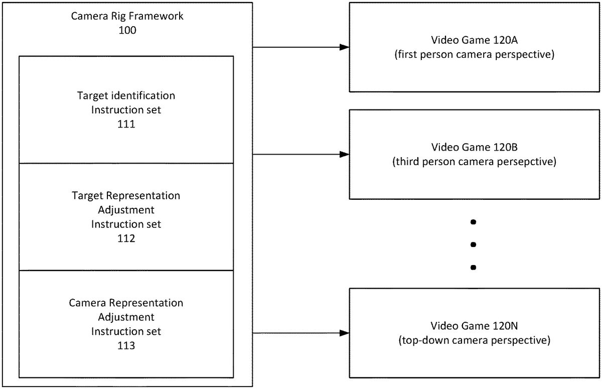
FIG. 1is a diagram illustrating an example camera rig framework that may be used in accordance with the present disclosure. In particular, in the example ofFIG. 1, camera rig framework100includes a target identification instruction set111, a target representation adjustment instruction set112, and a camera representation adjustment instruction set113. As will be described in greater detail below, target identification instruction set111may generally include instructions for identifying one or more targets within a virtual area of a video game. The target identification instruction set may also include instructions for determining an original target representation based, at least in part, on the one or more identified targets. Target representation adjustment instruction set112may generally include instructions for adjusting the target representation, for example based on various target representation adjustment behaviors as described in detail below. Camera representation adjustment instruction set113may generally include instructions for adjusting a camera representation, for example based on various camera representation adjustment behaviors as described in detail below.
As also shown inFIG. 1, camera rig framework100may be employed and reused for controlling a camera in video games120A-N. In the particular example ofFIG. 1, video game120A employs a first person camera perspective, video game120B employs a third person camera perspective, and video game120N employs a top-down camera perspective. It is noted, however, that camera rig framework100may be employed for any number of different video games employing any combination of these or other camera perspectives. It is further noted that camera rig framework100may be employed for a variety of different video game contexts, such as combat games, sports games, fantasy games, car and other racing games, and many others. As will be described in detail below, instruction sets111,112and113may be both modifiable and extendible to different camera and game contexts, for example allowing developers to easily generate new camera behaviors for their games and also to modify existing available camera behaviors to better match their particular camera and game contexts.
Some example features of target identification instruction set111will now be described in detail. In particular, in some examples, target identification instruction set111may include indications of a plurality of selected targets. A target may include, for example, one or more objects, portions of objects, or locations, within a virtual area, based, at least in part, upon which a camera may be positioned and/or oriented. For example, for a car racing game, targets may include one or more cars within the game, such as cars crossing the finish line, cars on fire, a car passing another car, a car in first place, a car operated by a particular player, and many others. For a combat game, a target may include one or more characters within the game, such as a character operated by a particular player, characters on a particular team, characters in combat, characters being killed, characters at a particular site or location, and many others. Many other types of targets may be selected for any number of the above or other types of different video game contexts.
The target identification instruction set111may include a hierarchy that prioritizes the selected targets relative to one another. Referring now toFIG. 2, an example target hierarchy200for a car racing game will now be described in detail. In the example ofFIG. 2, target hierarchy200includes a highest priority target node201(cars crossing the finish line), a second highest priority target node202(cars on fire), third highest priority target node203(car passing other car), and a fourth highest priority target node204(car in first place). In some examples, a video game may traverse a target hierarchy, starting by considering a highest priority target node and subsequently considering each next highest priority target node, until one or more targets associated with a target node have been identified within a virtual area of the video game. For example, a car racing video game may traverse target hierarchy200by first considering highest priority node201, which may include determining whether any car is currently crossing the finish line. If so, then that car may be selected as the identified target and traversal of the target hierarchy200may stop at node201. If not, then the video game may proceed to consider second highest priority target node202by determining whether any cars are currently on fire (e.g., involved in a crash). If so, then those cars may be selected as the identified targets and traversal of the target hierarchy200may stop at node202. If not, then the video game may proceed to consider third highest priority target node203by determining whether any car is currently passing another car. If so, then that car may be selected as the identified target and traversal of the target hierarchy200may stop at node203. If not, then the video game may proceed to consider fourth highest priority target node204by determining which car is currently in first place. The first place car may then be selected as the identified target and traversal of the target hierarchy200may stop at node204.
In some examples, target identification instruction set111may include instructions for identifying one or more targets for each frame generated during the course of the video game or on another periodic basis, such as a selected quantity of frames, in response to particular events, or based on other factors. It is noted however, that it may not be necessary to traverse a target hierarchy for each frame or for every time that a target is identified. For example, in some cases, for video game contexts in which identified targets are not expected to change frequently, it may only be necessary to traverse the target hierarchy a single time or on another less frequent basis (e.g., every one thousand frames, every twenty seconds, etc.). In some examples, for frames in which the target hierarchy is not re-traversed, it may only be necessary to update the position and/or orientation of a previously identified target (as opposed to identifying a new target).
In some examples, a target hierarchy may include tags or other identifiers for various targets included within the hierarchy, and these tags may match tags that are used by the video game to identify respective objects within the video game itself. For example, node202of target hierarchy200may include a FIRE tag that is used by a respective video game to identify cars that are on fire within the video game. When the video game is considering node202to identify whether there are currently any cars on fire, the video game may simply attempt to match the FIRE tag in node202to a corresponding tag attached to one or more objects that currently exist within the video game's virtual area. If there are one or more matching tags, then thee objects associated with those tags may be identified as targets.
The target identification instruction set111may also include instructions for determining an original target representation based, at least in part, on the one or more identified targets. A target representation may include a representation (e.g., point, location, orientation, etc.), which is associated with one or more targets, relative to which the camera may be rotated, extended, and/or otherwise manipulated. For example, for a car racing game, a target may sometimes be identified as a particular race car, and a target representation may sometimes be selected as a particular point, location, and/or orientation on the target race car (e.g., a center point or geometric origin of the race car).
In some examples, target identification instruction set111may also include instructions for determining the original target representation when multiple targets have been identified for a given frame. For example, in some cases, when multiple targets are identified, the original target representation may sometimes be selected as an average (e.g., center point or mid-point) location between the multiple targets. In other examples, the targets may be weighted relative to one another, and the original target representation may be selected as a weighted average location between the multiple targets. Any combination of these or many other additional factors may be employed to determine an original target representation for multiple identified targets.
Some example features of target representation adjustment instruction set112will now be described in detail. As set forth above, the target representation adjustment instruction set112may include instructions for adjusting the target representation, for example by rotating and/or moving (e.g., offsetting) the target representation. In particular, the target representation adjustment instruction set112may include one or more selected target representation adjustment behaviors. Referring now toFIG. 3, some example target representation adjustment behaviors351-353will now be described in detail. Example behaviors351-353relate to a third-person camera perspective in which a character311is identified as a target and a target representation312is then determined based on the character311. Additionally, a camera310follows the character311at a specified distance from the target representation312. As shown inFIG. 3, in example behavior351, character311remains stationary (i.e., does not move). However, target representation312is adjusted by performing a yaw rotation to the target representation312(e.g., in a clockwise or counterclockwise manner). The yaw rotation of the target representation312causes camera310to responsively rotate around the stationary character311. Behavior351may be advantageous, for example, by allowing a player to view character311from various different perspectives, such as to view injuries or damage sustained by the character311or for many other reasons.
In example behavior352, character311again remains stationary (i.e., does not move). However, in this example, target representation312is adjusted by pitching the target representation312(as indicated by the pitch directional arrow313). Pitching of the target representation312causes camera310to responsively rotate up or down. Behavior352may be advantageous, for example, by allowing a player to rotate the camera view up or down in scenarios when a character311does not (or cannot) pitch up or down.
In example behavior353, character311has a pitch rotation. The pitch rotation of character311, in turn, causes target representation312to responsively have a pitch rotation. Additionally, the pitch rotation of target representation312, in turn, causes camera310to responsively rotate up or down. However, in this example, target representation312is adjusted by sliding the target representation312forward to a location in front of character311. The forward movement of target representation312, in turn, causes camera310to responsively slide forward towards the front of character311. Behavior353may be advantageous, for example, because, in certain third-person camera scenarios, an up or down pitch of a target character may tend to cause the target character to substantially block or obstruct the camera view. By sliding the camera310forward towards the front of the character311, the camera310is able to rotate up or down while simultaneously reducing an extent to which the pitch of the character311blocks or obstructs the camera view.
It is noted that behaviors351-353are merely intended as non-limiting descriptive examples of certain target representation adjustment behaviors. It is noted that any combination of these or other target representation adjustment behaviors may be selected and employed in accordance with the camera rig framework described herein. It is also noted that, in addition to behaviors themselves, target representation adjustment instruction set112may also include respective instructions for implementing each behavior as well as one or more respective conditions for triggering each behavior. For example, in some cases, behavior351may be triggered by holding down a particular button (e.g., a X button) on a controller and moving a directional control left or right depending on the desired direction of rotation of the camera310. As another example, in some cases, behavior352may be triggered by holding down a particular button (e.g., a Y button) on a controller and moving a directional control up or down depending on the desired direction of rotation of the camera310. As yet another example, in some cases, behavior353may be triggered by pitch rotation of character311.
Some example features of camera representation adjustment instruction set113will now be described in detail. As set forth above, the camera representation adjustment instruction set113may include instructions for adjusting the camera representation, for example relative to the target representation. In particular, the camera representation adjustment instruction set113may include one or more selected camera representation adjustment behaviors. In some examples, a selected camera representation adjustment behavior may include following a target representation form a particular distance and/or angle, limiting a camera representation to particular amount of acceleration or movement, and/or many other different behaviors.
Referring now toFIG. 4A, some example camera representation adjustment behaviors431-434will now be described in detail. Example behaviors431-434relate to a car racing game in which a car414is identified as a target and a target representation312is then determined based on the car414. In particular, behaviors431-433illustrate different behaviors in which the camera representation410follows (e.g., is extended from) the target representation312by various different distances. Specifically, in behavior431, the camera representation410follows the target representation312by a shorter distance411. In behavior432, the camera representation410follows the target representation312by an intermediate distance412. In behavior433, the camera representation410follows the target representation312by a longer distance413. Behavior434illustrates an example in which camera representation410follows target representation312by a particular distance416and a particular angle415(e.g., between lines416and417).
In addition to behaviors themselves, camera representation adjustment instruction set113may also include may also include respective instructions for implementing each behavior as well as one or more respective conditions for triggering each behavior. For example, in some cases, behaviors431-434may be triggered by different states or conditions associated with the target car414. As an example, in some cases, when a car is driving straight, the camera representation may follow the target representation from a shorter distance and from a straight (i.e., zero degree) angle. By contrast, when a car is turning, the camera representation may follow the target representation from a longer distance and from a diagonal (i.e., non-zero degree) angle. In other examples, the distance and/or angle of the camera representation relative to the target representation may also vary based on other factors, such as the speed or of the car, a stage of game play, a performance (e.g., first place, last place) of the car, a setting (e.g., city, desert, forest, etc.), a location, a time of day, proximity of the car to other cars, a number of identified targets, and many other factors.
In some examples, camera representation adjustment instruction set113may also include various restrictions, rules, or other instructions for regulating adjustment of the camera representation. For example, in some cases, camera representation adjustment instruction set113may include rules related to how quickly the camera representation is permitted to accelerate. Such rules may be advantageous, for example, by allowing the camera view to effectively provide an indication to a viewer of how quickly a target is moving, accelerating and/or decelerating. For example, in some cases, increasing the distance between the camera and the target may create an appearance that a target is accelerating, while decreasing the distance between the camera and the target may create an appearance that a car is decelerating or stabilizing its speed. Referring now toFIG. 4B, an example camera representation adjustment rule will now be described in detail. In particular,FIG. 4Billustrates an example rule that limits acceleration of a camera. As shown inFIG. 4B, at frame441, car414is traveling at a lower speed, and camera representation410follows target representation312by a shorter follow behind distance421. Subsequently, at frame442, the car414accelerates more rapidly than the camera representation410is permitted to accelerate. As a result, camera representation410follows target representation312by an increased follow behind distance422. It is noted that the follow behind distance may be increased over time as car414accelerates and that frame442is not necessarily a frame that immediately follows frame441. Finally, at frame443, the car414decelerates and returns to a lower speed. As a result, camera representation410catches up and returns to following target representation312by a shorter follow behind distance423. It is noted that the follow behind distance may be decreased over time as car414decelerates and that frame443is not necessarily a frame that immediately follows frame442. As set forth above, in some examples, by limiting the acceleration of the camera representation in this manner, the video game may effectively provide an indication to a viewer of how quickly a target is moving, accelerating and/or decelerating.
It is noted thatFIGS. 4A and 4Bare merely intended as non-limiting descriptive examples of certain camera representation adjustment behaviors and rules. It is noted that any combination of these or other camera representation adjustment behaviors and rules may be selected and employed in accordance with the camera rig framework described herein. For example, in some cases, a security camera behavior may be employed in which the camera representation remains at the same location but may rotate (e.g., pitch, yaw, etc.) to be pointing towards a target as it moves throughout a virtual area. As another example, a fly-by camera behavior may be employed in which the camera travels along a determined path, such as to mimic a camera that travels along a cable, is suspended from a plane, etc. Any combination of these or other camera representation behaviors and/or rules may be selected and employed.
Referring now toFIG. 5, an example camera rig configuration system will now be described in detail. In particular, in the example ofFIG. 5, a video game development interface500is employed, for example by a video game developer, to configure operation of a camera rig for a video game120. In some examples, video game development interface500may be exposed by a computing service provider that hosts execution of video game120, such as via operation of one or more data centers or other computing services. Also, in some examples, any or all of the functionality described in relation to video game development interface500may be implemented via a software development kit (SDK), an application programming interface (API), or other interfaces or instructions, for example provided by the above described computing services provider or another party.
As shown inFIG. 5, video game development interface500includes a target identification section510, a target representation adjustment section520, and a camera representation adjustment section530. In particular, target identification section510includes objects511-514, which are objects that are made available by interface500and may be selected for inclusion in target hierarchy200. For example, for car racing games, objects511-514may include objects such as cars crossing the finish line, cars on fire, cars in first place, and many others. Selection of one or more of objects511-514via interface500may cause the selected objects to be included in the target hierarchy200and, in turn, in target identification instruction set111and video game120. In the example ofFIG. 5, a user has selected objects513and514as indicated by the X symbol in the checkboxes adjacent to objects513and514. In some examples, interface500may expose a tag or other identifier for each of objects511-514, which may be inserted into the target hierarchy200upon selection of the object. In some examples, the exposed tag may be modifiable via interface500, for example if the user wishes to modify the tag in order to match a respective tag used to identify a corresponding object in video game120. Create custom object control515may allow a user to create custom objects for inclusion in target hierarchy200and to provide respective custom tags for the custom objects. Prioritize selected objects control516may allow users to prioritize selected objects within the target hierarchy200. For example, with reference to nodes201-204ofFIG. 2, a user may use control516to assign a highest priority to cars crossing the finish line, a second highest priority to cars on fire, a third highest priority to a car passing another car, and a fourth highest priority to a car in first place.
Target representation adjustment section520includes target representation adjustment behaviors521-524, which are behaviors that are made available by interface500and may be selected for inclusion in target representation adjustment instruction set112and video game120. For example, target representation adjustment behaviors521-524may include any or all of the example target representation adjustment behaviors351-353described above with reference toFIG. 3or other target representation adjustment behaviors. Selection of one or more of behaviors521-524via interface500may cause instructions for implementing the selected behaviors to be included in the target representation adjustment instruction set112and video game120. In the example ofFIG. 5, a user has selected behaviors522and523, which, in turn causes behavior instructions542(for behavior522) and behavior instructions543(for behavior523) to be inserted into target representation adjustment instruction set112and video game120. In some examples, behavior instructions542and543may be pre-generated instructions that are exposed and provided by interface500. Also, in some examples, any or all portions of instructions542and543may be modifiable via interface500, for example to be better configured for particular camera and game contexts. Additionally, create custom behavior control525allows a user to generate custom target representation adjustment behaviors, for example for particular camera and game contexts. Selection of control525may also allow a user to generate, via interface500, behavior instructions545for implementing a custom target representation adjustment behavior, and these instructions545may also be inserted into target representation adjustment instruction set112and video game120.
Camera representation adjustment section530includes camera representation adjustment behaviors531-534, which are behaviors that are made available by interface500and may be selected for inclusion in camera representation adjustment instruction set113and video game120. For example, camera representation adjustment behaviors531-534may include any or all of the example camera representation adjustment behaviors431-434described above with reference toFIG. 4Aor other camera representation adjustment behaviors. Selection of one or more of behaviors531-534via interface500may cause instructions for implementing the selected behaviors to be included in the camera representation adjustment instruction set113and video game120. In the example ofFIG. 5, a user has selected behaviors531and534, which, in turn causes behavior instructions551(for behavior531) and behavior instructions554(for behavior534) to be inserted into camera representation adjustment instruction set113and video game120. In some examples, behavior instructions551and554may be pre-generated instructions that are exposed and provided by interface500. Also, in some examples, any or all portions of instructions551and554may be modifiable via interface500, for example to be better configured for particular camera and game contexts. Additionally, create custom behavior control535allows a user to generate custom camera representation adjustment behaviors, for example for particular camera and game contexts. Selection of control535may also allow a user to generate, via interface500, camera representation adjustment behavior instructions555for implementing a custom behavior, and these instructions555may also be inserted into camera representation adjustment instruction set113and video game120.
Referring now toFIG. 6, an example process for controlling a virtual camera will now be described in detail. In some examples, the process depicted inFIG. 6may be performed by an executing video game, for example on a frame-by-frame or other periodic basis. In particular, the process ofFIG. 6is initiated at operation610, at which one or more targets are identified within a virtual area of a video game. As set forth above, a target may include, for example, one or more objects, portions of objects, or locations, within a virtual area, based, at least in part, upon which a camera may be positioned and/or oriented. The one or more targets are identified at operation610based, at least in part, on a traversal of at least part of a hierarchy of targets, such as example target hierarchy200ofFIG. 2. For example, a hierarchy of targets may be traversed from a highest priority node to a lowest priority node until one or more targets associated with a node are identified within the virtual area of the video game. As also set forth above, the target hierarchy may be included in a target identification instruction set, for example that is generated using a video game development interface such as interface500ofFIG. 5.
At operation612, an original target representation is determined based, at least in part, on the one or more targets identified at operation610. As set forth above, a target representation may include a representation (e.g., point, location, orientation, etc.), which is associated with one or more targets, relative to which the camera may be rotated, extended, and/or otherwise manipulated. In some examples, the original target representation may be set to a particular point (e.g., a center point or geometric origin), location, and/or orientation of an identified target. In some examples, when multiple targets are identified, the original target representation may sometimes be selected as an average (e.g., center point or mid-point) or weighted average location between the multiple targets. Any combination of these or other techniques may be employed to determine an original target representation.
At operation614, it is determined whether one or more conditions associated with at least a first target representation adjustment behavior are satisfied. As set forth above, a target representation adjustment behavior may include, for example, a rotation and/or a movement of the target representation. Some example target representation adjustment behaviors, such as behaviors351-353ofFIG. 3, are described in detail above and are not repeated here. As also set forth above, a video game development interface, such as interface500ofFIG. 5, may expose various available target representation adjustment behaviors from which the first target representation adjustment behavior may be selected. Each of the available target representation adjustment behaviors may have a respective associated set of modifiable instructions for implementing the behavior, and selection of a behavior may cause its respective instructions to be provided by the video game development interface for inclusion in a video game. The video game development interface may also allow generation of custom target representation adjustment behaviors not included in the available behaviors exposed by the interface. The video game development interface may also allow a developer to indicate one or more conditions associated with each selected target representation adjustment behavior for triggering application of the associated behavior. These trigger conditions may also be included, for example via the interface, in the video game, and the video game may examine these associated conditions to determine whether one or more conditions are satisfied in order to trigger application of an associated behavior. Some example conditions may include, for example, various user inputs, selection of various controls, character movements, game states, object characteristics, locations, times, and other conditions. Some example conditions for triggering example behaviors351-353ofFIG. 3, are described in detail above and are not repeated here.
If one or more conditions associated with at least a first target representation adjustment behavior are not satisfied (or if such conditions and/or behaviors do not exist within the context of the video game), then the process may proceed to operation616, at which the original target representation is used as a final target representation. If, however, one or more conditions associated with at least a first target representation adjustment behavior are satisfied, then the process may proceed to operation618, at which the original target representation is adjusted to a final target representation based, at least in part, on instructions associated with the first target representation adjustment behavior. For example, if the first target adjustment behavior includes a rotation and/or movement of the target representation, then the associated instructions may include instructions for rotating and/or moving the target representation in a specified rotation (e.g., pitch, yaw, roll, etc.) and/or direction, by a specified amount (e.g., degree, distance, etc.), and/or other instructions.
In some examples, at operation614, conditions associated with triggering multiple target representation adjustment behaviors may be determined to be satisfied. In these examples, operation618may include iterating through each of the multiple target representation adjustment behaviors. For example, the original target representation may be adjusted to a first current target representation based instructions for the first target representation, and the first current target representation may then be adjusted to a second current target representation based on instructions for a second target representation adjustment behavior. The current target representation may continue to be adjusted for each successive target adjustment behavior until all triggered behaviors are applied and a final target representation is set.
At operation620, an original camera representation is set to a position and an orientation of the final target representation. At operation622, it is determined whether one or more conditions associated with at least a first camera representation adjustment behavior are satisfied. As set forth above, a camera representation adjustment behavior may include, for example, an adjustment to the original camera representation relative to the target representation by at least one of a distance or an angle. Some example camera representation adjustment behaviors, such as behaviors431-434ofFIG. 4A, are described in detail above and are not repeated here. As also set forth above, a video game development interface, such as interface500ofFIG. 5, may expose various available camera representation adjustment behaviors from which the first camera representation adjustment behavior may be selected. Each of the available camera representation adjustment behaviors may have a respective associated set of modifiable instructions for implementing the behavior, and selection of a behavior may cause its respective instructions to be provided by the video game development interface for inclusion in a video game. The video game development interface may also allow generation of custom camera representation adjustment behaviors not included in the available behaviors exposed by the interface. The video game development interface may also allow a developer to indicate one or more conditions associated with each selected camera representation adjustment behavior for triggering application of the associated behavior. These trigger conditions may also be included, for example via the interface, in the video game, and the video game may examine these associated conditions to determine whether one or more conditions are satisfied in order to trigger application of an associated behavior. Some example conditions may include, for example, various states or conditions (e.g., speed, orientation, direction, etc.) associated with one or more targets, a stage and/or state of game play, a performance (e.g., first place, last place) of a target, a setting (e.g., city, desert, forest, etc.), a location, a time of day, proximity of a target to other objects, a number of identified targets, and many other factors.
If one or more conditions associated with at least a first camera representation adjustment behavior are not satisfied (or if such conditions and/or behaviors do not exist within the context of the video game), then the process may proceed to operation624, at which the original camera representation is used as a final camera representation. If, however, one or more conditions associated with at least a first camera representation adjustment behavior are satisfied, then the process may proceed to operation626, at which the original camera representation is adjusted to a final camera representation based, at least in part, on the final target representation and on instructions associated with the first camera representation adjustment behavior. For example, if the first camera adjustment behavior includes an adjustment to the camera representation relative to the target representation, then the associated instructions may include instructions for extending the camera representation from the target representation by a specified distance and/or angle or otherwise manipulating the camera representation relative to the target representation.
Additionally, it is noted that, at least because the final target representation is used to set the position and the orientation of the original camera representation, the adjustment to the original target representation is also based, at least in part, on the final target representation. Moreover, in some cases, the final target representation may also be used to limit an amount (e.g., a distance or a degree of rotation) by which the final camera representation may be adjusted relative to the final target representation. For example, in some cases, target adjustment behavior instructions within the video game may include rules requiring that the final camera representation must remain within a specified distance, degree of rotation, or other orientation or position relative to the final target representation.
In some examples, at operation622, conditions associated with triggering multiple camera representation adjustment behaviors may be determined to be satisfied. In these examples, operation626may include iterating through each of the multiple camera representation adjustment behaviors. For example, the original camera representation may be adjusted to a first current camera representation based instructions for the first camera representation, and the first current camera representation may then be adjusted to a second current camera representation based on instructions for a second camera representation adjustment behavior. The current camera representation may continue to be adjusted for each successive camera adjustment behavior until all triggered behaviors are applied and a final camera representation is set.
At operation628, a position and an orientation of the virtual camera is set based, at least in part, on the final camera representation. Under typical circumstances, it is expected that operation628may include simply setting the virtual camera to have the same position and orientation as the final camera representation. In some cases, however, it may be potentially desirable to otherwise manipulate the position and orientation of the virtual camera, for example for certain game-specific reasons that are not described herein.
As also described above, in some examples, an interface may be provided that allows reception of information associated with a target identification instruction set, information associated with a target representation adjustment instruction set, and information associated with a camera representation adjustment instruction set. The target identification instruction set and/or information associated therewith may comprise a hierarchy of targets that is traversable to identify one or more targets within a virtual area of a video game. The target representation adjustment instruction set and/or information associated therewith may comprise at least a first target representation adjustment behavior for adjusting a target representation. The camera representation adjustment instruction set and/or information associated therewith may comprise at least a first camera representation adjustment behavior for adjusting a camera representation. The information associated with the target identification instruction set, the information associated with the target representation adjustment instruction set, and the information associated with the camera representation adjustment instruction set may be received via the interface. The target identification instruction set, the target representation adjustment instruction set, and the camera representation adjustment instruction set are insertable into, and may be inserted into, the video game to control a virtual camera in the virtual area of the video game.
An example system for transmitting and providing data will now be described in detail. In particular,FIG. 7illustrates an example computing environment in which the embodiments described herein may be implemented.FIG. 7is a diagram schematically illustrating an example of a data center85that can provide computing resources to users70aand70b(which may be referred herein singularly as user70or in the plural as users70) via user computers72aand72b(which may be referred herein singularly as computer72or in the plural as computers72) via a communications network73. Data center85may be configured to provide computing resources for executing applications on a permanent or an as-needed basis. The computing resources provided by data center85may include various types of resources, such as gateway resources, load balancing resources, routing resources, networking resources, computing resources, volatile and non-volatile memory resources, content delivery resources, data processing resources, data storage resources, data communication resources and the like. Each type of computing resource may be available in a number of specific configurations. For example, data processing resources may be available as virtual machine instances that may be configured to provide various web services. In addition, combinations of resources may be made available via a network and may be configured as one or more web services. The instances may be configured to execute applications, including web services, such as application services, media services, database services, processing services, gateway services, storage services, routing services, security services, encryption services, load balancing services, application services and the like. These services may be configurable with set or custom applications and may be configurable in size, execution, cost, latency, type, duration, accessibility and in any other dimension. These web services may be configured as available infrastructure for one or more clients and can include one or more applications configured as a platform or as software for one or more clients. These web services may be made available via one or more communications protocols. These communications protocols may include, for example, hypertext transfer protocol (HTTP) or non-HTTP protocols. These communications protocols may also include, for example, more reliable transport layer protocols, such as transmission control protocol (TCP), and less reliable transport layer protocols, such as user datagram protocol (UDP). Data storage resources may include file storage devices, block storage devices and the like.
Each type or configuration of computing resource may be available in different sizes, such as large resources—consisting of many processors, large amounts of memory and/or large storage capacity—and small resources—consisting of fewer processors, smaller amounts of memory and/or smaller storage capacity. Customers may choose to allocate a number of small processing resources as web servers and/or one large processing resource as a database server, for example.
Data center85may include servers76aand76b(which may be referred herein singularly as server76or in the plural as servers76) that provide computing resources. These resources may be available as bare metal resources or as virtual machine instances78a-d(which may be referred herein singularly as virtual machine instance78or in the plural as virtual machine instances78).
The availability of virtualization technologies for computing hardware has afforded benefits for providing large scale computing resources for customers and allowing computing resources to be efficiently and securely shared between multiple customers. For example, virtualization technologies may allow a physical computing device to be shared among multiple users by providing each user with one or more virtual machine instances hosted by the physical computing device. A virtual machine instance may be a software emulation of a particular physical computing system that acts as a distinct logical computing system. Such a virtual machine instance provides isolation among multiple operating systems sharing a given physical computing resource. Furthermore, some virtualization technologies may provide virtual resources that span one or more physical resources, such as a single virtual machine instance with multiple virtual processors that span multiple distinct physical computing systems.
Referring toFIG. 7, communications network73may, for example, be a publicly accessible network of linked networks and possibly operated by various distinct parties, such as the Internet. In other embodiments, communications network73may be a private network, such as a corporate or university network that is wholly or partially inaccessible to non-privileged users. In still other embodiments, communications network73may include one or more private networks with access to and/or from the Internet.
Communication network73may provide access to computers72. User computers72may be computers utilized by users70or other customers of data center85. For instance, user computer72aor72bmay be a server, a desktop or laptop personal computer, a tablet computer, a wireless telephone, a personal digital assistant (PDA), an e-book reader, a game console, a set-top box or any other computing device capable of accessing data center85. User computer72aor72bmay connect directly to the Internet (e.g., via a cable modem or a Digital Subscriber Line (DSL)). Although only two user computers72aand72bare depicted, it should be appreciated that there may be multiple user computers.
User computers72may also be utilized to configure aspects of the computing resources provided by data center85. In this regard, data center85might provide a gateway or web interface through which aspects of its operation may be configured through the use of a web browser application program executing on user computer72. Alternately, a stand-alone application program executing on user computer72might access an application programming interface (API) exposed by data center85for performing the configuration operations. Other mechanisms for configuring the operation of various web services available at data center85might also be utilized.
Servers76shown inFIG. 7may be servers configured appropriately for providing the computing resources described above and may provide computing resources for executing one or more web services and/or applications. In one embodiment, the computing resources may be virtual machine instances78. In the example of virtual machine instances, each of the servers76may be configured to execute an instance manager80aor80b(which may be referred herein singularly as instance manager80or in the plural as instance managers80) capable of executing the virtual machine instances78. The instance managers80may be a virtual machine monitor (VMM) or another type of program configured to enable the execution of virtual machine instances78on server76, for example. As discussed above, each of the virtual machine instances78may be configured to execute all or a portion of an application.
It should be appreciated that although the embodiments disclosed above discuss the context of virtual machine instances, other types of implementations can be utilized with the concepts and technologies disclosed herein. For example, the embodiments disclosed herein might also be utilized with computing systems that do not utilize virtual machine instances.
In the example data center85shown inFIG. 7, a router71may be utilized to interconnect the servers76aand76b. Router71may also be connected to gateway74, which is connected to communications network73. Router71may be connected to one or more load balancers, and alone or in combination may manage communications within networks in data center85, for example, by forwarding packets or other data communications as appropriate based on characteristics of such communications (e.g., header information including source and/or destination addresses, protocol identifiers, size, processing requirements, etc.) and/or the characteristics of the private network (e.g., routes based on network topology, etc.). It will be appreciated that, for the sake of simplicity, various aspects of the computing systems and other devices of this example are illustrated without showing certain conventional details. Additional computing systems and other devices may be interconnected in other embodiments and may be interconnected in different ways.
In the example data center85shown inFIG. 7, a server manager75is also employed to at least in part direct various communications to, from and/or between servers76aand76b. WhileFIG. 7depicts router71positioned between gateway74and server manager75, this is merely an exemplary configuration. In some cases, for example, server manager75may be positioned between gateway74and router71. Server manager75may, in some cases, examine portions of incoming communications from user computers72to determine one or more appropriate servers76to receive and/or process the incoming communications. Server manager75may determine appropriate servers to receive and/or process the incoming communications based on factors such as an identity, location or other attributes associated with user computers72, a nature of a task with which the communications are associated, a priority of a task with which the communications are associated, a duration of a task with which the communications are associated, a size and/or estimated resource usage of a task with which the communications are associated and many other factors. Server manager75may, for example, collect or otherwise have access to state information and other information associated with various tasks in order to, for example, assist in managing communications and other operations associated with such tasks.
It should be appreciated that the network topology illustrated inFIG. 7has been greatly simplified and that many more networks and networking devices may be utilized to interconnect the various computing systems disclosed herein. These network topologies and devices should be apparent to those skilled in the art.
It should also be appreciated that data center85described inFIG. 7is merely illustrative and that other implementations might be utilized. It should also be appreciated that a server, gateway or other computing device may comprise any combination of hardware or software that can interact and perform the described types of functionality, including without limitation: desktop or other computers, database servers, network storage devices and other network devices, PDAs, tablets, cellphones, wireless phones, pagers, electronic organizers, Internet appliances, television-based systems (e.g., using set top boxes and/or personal/digital video recorders) and various other consumer products that include appropriate communication capabilities.
In at least some embodiments, a server that implements a portion or all of one or more of the technologies described herein may include a computer system that includes or is configured to access one or more computer-accessible media.FIG. 8depicts a computer system that includes or is configured to access one or more computer-accessible media. In the illustrated embodiment, computing device15includes one or more processors10a,10band/or10n(which may be referred herein singularly as “a processor10” or in the plural as “the processors10”) coupled to a system memory20via an input/output (I/O) interface30. Computing device15further includes a network interface40coupled to I/O interface30.
In various embodiments, computing device15may be a uniprocessor system including one processor10or a multiprocessor system including several processors10(e.g., two, four, eight or another suitable number). Processors10may be any suitable processors capable of executing instructions. For example, in various embodiments, processors10may be embedded processors implementing any of a variety of instruction set architectures (ISAs), such as the x86, PowerPC, SPARC or MIPS ISAs or any other suitable ISA. In multiprocessor systems, each of processors10may commonly, but not necessarily, implement the same ISA.
System memory20may be configured to store instructions and data accessible by processor(s)10. In various embodiments, system memory20may be implemented using any suitable memory technology, such as static random access memory (SRAM), synchronous dynamic RAM (SDRAM), nonvolatile/Flash®-type memory or any other type of memory. In the illustrated embodiment, program instructions and data implementing one or more desired functions, such as those methods, techniques and data described above, are shown stored within system memory20as code25and data26.
In one embodiment, I/O interface30may be configured to coordinate I/O traffic between processor10, system memory20and any peripherals in the device, including network interface40or other peripheral interfaces. In some embodiments, I/O interface30may perform any necessary protocol, timing or other data transformations to convert data signals from one component (e.g., system memory20) into a format suitable for use by another component (e.g., processor10). In some embodiments, I/O interface30may include support for devices attached through various types of peripheral buses, such as a variant of the Peripheral Component Interconnect (PCI) bus standard or the Universal Serial Bus (USB) standard, for example. In some embodiments, the function of I/O interface30may be split into two or more separate components, such as a north bridge and a south bridge, for example. Also, in some embodiments some or all of the functionality of I/O interface30, such as an interface to system memory20, may be incorporated directly into processor10.
Network interface40may be configured to allow data to be exchanged between computing device15and other device or devices60attached to a network or networks50, such as other computer systems or devices, for example. In various embodiments, network interface40may support communication via any suitable wired or wireless general data networks, such as types of Ethernet networks, for example. Additionally, network interface40may support communication via telecommunications/telephony networks, such as analog voice networks or digital fiber communications networks, via storage area networks such as Fibre Channel SANs (storage area networks) or via any other suitable type of network and/or protocol.
In some embodiments, system memory20may be one embodiment of a computer-accessible medium configured to store program instructions and data as described above for implementing embodiments of the corresponding methods and apparatus.
However, in other embodiments, program instructions and/or data may be received, sent or stored upon different types of computer-accessible media. Generally speaking, a computer-accessible medium may include non-transitory storage media or memory media, such as magnetic or optical media—e.g., disk or DVD/CD coupled to computing device15via I/O interface30. A non-transitory computer-accessible storage medium may also include any volatile or non-volatile media, such as RAM (e.g., SDRAM, DDR SDRAM, RDRAM, SRAM, etc.), ROM (read only memory) etc., that may be included in some embodiments of computing device15as system memory20or another type of memory. Further, a computer-accessible medium may include transmission media or signals such as electrical, electromagnetic or digital signals conveyed via a communication medium, such as a network and/or a wireless link, such as those that may be implemented via network interface40.
A network set up by an entity, such as a company or a public sector organization, to provide one or more web services (such as various types of cloud-based computing or storage) accessible via the Internet and/or other networks to a distributed set of clients may be termed a provider network. Such a provider network may include numerous data centers hosting various resource pools, such as collections of physical and/or virtualized computer servers, storage devices, networking equipment and the like, needed to implement and distribute the infrastructure and web services offered by the provider network. The resources may in some embodiments be offered to clients in various units related to the web service, such as an amount of storage capacity for storage, processing capability for processing, as instances, as sets of related services and the like. A virtual computing instance may, for example, comprise one or more servers with a specified computational capacity (which may be specified by indicating the type and number of CPUs, the main memory size and so on) and a specified software stack (e.g., a particular version of an operating system, which may in turn run on top of a hypervisor).
A compute node, which may be referred to also as a computing node, may be implemented on a wide variety of computing environments, such as commodity-hardware computers, virtual machines, web services, computing clusters and computing appliances. Any of these computing devices or environments may, for convenience, be described as compute nodes.
A number of different types of computing devices may be used singly or in combination to implement the resources of the provider network in different embodiments, for example computer servers, storage devices, network devices and the like. In some embodiments a client or user may be provided direct access to a resource instance, e.g., by giving a user an administrator login and password. In other embodiments the provider network operator may allow clients to specify execution requirements for specified client applications and schedule execution of the applications on behalf of the client on execution platforms (such as application server instances, Java™ virtual machines (JVMs), general-purpose or special-purpose operating systems, platforms that support various interpreted or compiled programming languages such as Ruby, Perl, Python, C, C++ and the like or high-performance computing platforms) suitable for the applications, without, for example, requiring the client to access an instance or an execution platform directly. A given execution platform may utilize one or more resource instances in some implementations; in other implementations, multiple execution platforms may be mapped to a single resource instance.
In many environments, operators of provider networks that implement different types of virtualized computing, storage and/or other network-accessible functionality may allow customers to reserve or purchase access to resources in various resource acquisition modes. The computing resource provider may provide facilities for customers to select and launch the desired computing resources, deploy application components to the computing resources and maintain an application executing in the environment. In addition, the computing resource provider may provide further facilities for the customer to quickly and easily scale up or scale down the numbers and types of resources allocated to the application, either manually or through automatic scaling, as demand for or capacity requirements of the application change. The computing resources provided by the computing resource provider may be made available in discrete units, which may be referred to as instances. An instance may represent a physical server hardware platform, a virtual machine instance executing on a server or some combination of the two. Various types and configurations of instances may be made available, including different sizes of resources executing different operating systems (OS) and/or hypervisors, and with various installed software applications, runtimes and the like. Instances may further be available in specific availability zones, representing a logical region, a fault tolerant region, a data center or other geographic location of the underlying computing hardware, for example. Instances may be copied within an availability zone or across availability zones to improve the redundancy of the instance, and instances may be migrated within a particular availability zone or across availability zones. As one example, the latency for client communications with a particular server in an availability zone may be less than the latency for client communications with a different server. As such, an instance may be migrated from the higher latency server to the lower latency server to improve the overall client experience.
In some embodiments the provider network may be organized into a plurality of geographical regions, and each region may include one or more availability zones. An availability zone (which may also be referred to as an availability container) in turn may comprise one or more distinct locations or data centers, configured in such a way that the resources in a given availability zone may be isolated or insulated from failures in other availability zones. That is, a failure in one availability zone may not be expected to result in a failure in any other availability zone. Thus, the availability profile of a resource instance is intended to be independent of the availability profile of a resource instance in a different availability zone. Clients may be able to protect their applications from failures at a single location by launching multiple application instances in respective availability zones. At the same time, in some implementations inexpensive and low latency network connectivity may be provided between resource instances that reside within the same geographical region (and network transmissions between resources of the same availability zone may be even faster).
As set forth above, content may be provided by a content provider to one or more clients. The term content, as used herein, refers to any presentable information, and the term content item, as used herein, refers to any collection of any such presentable information. A content provider may, for example, provide one or more content providing services for providing content to clients. The content providing services may reside on one or more servers. The content providing services may be scalable to meet the demands of one or more customers and may increase or decrease in capability based on the number and type of incoming client requests. Portions of content providing services may also be migrated to be placed in positions of reduced latency with requesting clients. For example, the content provider may determine an “edge” of a system or network associated with content providing services that is physically and/or logically closest to a particular client. The content provider may then, for example, “spin-up,” migrate resources or otherwise employ components associated with the determined edge for interacting with the particular client. Such an edge determination process may, in some cases, provide an efficient technique for identifying and employing components that are well suited to interact with a particular client, and may, in some embodiments, reduce the latency for communications between a content provider and one or more clients.
In addition, certain methods or process blocks may be omitted in some implementations. The methods and processes described herein are also not limited to any particular sequence, and the blocks or states relating thereto can be performed in other sequences that are appropriate. For example, described blocks or states may be performed in an order other than that specifically disclosed, or multiple blocks or states may be combined in a single block or state. The example blocks or states may be performed in serial, in parallel or in some other manner. Blocks or states may be added to or removed from the disclosed example embodiments.
It will also be appreciated that various items are illustrated as being stored in memory or on storage while being used, and that these items or portions thereof may be transferred between memory and other storage devices for purposes of memory management and data integrity. Alternatively, in other embodiments some or all of the software modules and/or systems may execute in memory on another device and communicate with the illustrated computing systems via inter-computer communication. Furthermore, in some embodiments, some or all of the systems and/or modules may be implemented or provided in other ways, such as at least partially in firmware and/or hardware, including, but not limited to, one or more application-specific integrated circuits (ASICs), standard integrated circuits, controllers (e.g., by executing appropriate instructions, and including microcontrollers and/or embedded controllers), field-programmable gate arrays (FPGAs), complex programmable logic devices (CPLDs), etc. Some or all of the modules, systems and data structures may also be stored (e.g., as software instructions or structured data) on a computer-readable medium, such as a hard disk, a memory, a network or a portable media article to be read by an appropriate drive or via an appropriate connection. The systems, modules and data structures may also be transmitted as generated data signals (e.g., as part of a carrier wave or other analog or digital propagated signal) on a variety of computer-readable transmission media, including wireless-based and wired/cable-based media, and may take a variety of forms (e.g., as part of a single or multiplexed analog signal, or as multiple discrete digital packets or frames). Such computer program products may also take other forms in other embodiments. Accordingly, the present invention may be practiced with other computer system configurations.
Conditional language used herein, such as, among others, “can,” “could,” “might,” “may,” “e.g.” and the like, unless specifically stated otherwise, or otherwise understood within the context as used, is generally intended to convey that certain embodiments include, while other embodiments do not include, certain features, elements, and/or steps. Thus, such conditional language is not generally intended to imply that features, elements and/or steps are in any way required for one or more embodiments or that one or more embodiments necessarily include logic for deciding, with or without author input or prompting, whether these features, elements and/or steps are included or are to be performed in any particular embodiment. The terms “comprising,” “including,” “having” and the like are synonymous and are used inclusively, in an open-ended fashion, and do not exclude additional elements, features, acts, operations and so forth. Also, the term “or” is used in its inclusive sense (and not in its exclusive sense) so that when used, for example, to connect a list of elements, the term “or” means one, some or all of the elements in the list.
While certain example embodiments have been described, these embodiments have been presented by way of example only and are not intended to limit the scope of the inventions disclosed herein. Thus, nothing in the foregoing description is intended to imply that any particular feature, characteristic, step, module or block is necessary or indispensable. Indeed, the novel methods and systems described herein may be embodied in a variety of other forms; furthermore, various omissions, substitutions and changes in the form of the methods and systems described herein may be made without departing from the spirit of the inventions disclosed herein. The accompanying claims and their equivalents are intended to cover such forms or modifications as would fall within the scope and spirit of certain of the inventions disclosed herein.
Claims
- A computing system comprising: one or more processors;and memory having stored therein processor-executable instructions that, upon execution by the one or more processors, cause the computing system to perform operations comprising: providing an interface that displays a first set of selectable identifiers, wherein the first set of selectable identifiers identifies a plurality of video game objects;receiving a first selection of a first identifier from the first set of selectable identifiers corresponding to a selected video game object of the plurality of video game objects;inserting the selected video game object into a hierarchy of targets including a plurality of nodes each associated with a corresponding video game object;traversing, by a video game, the hierarchy of targets from a highest priority node of the plurality of nodes towards a lowest priority node of the plurality of nodes until an identified video game object associated with one of the plurality of nodes is identified by the video game within a virtual area of the video game;determining that the identified video game object is a target of a virtual camera of the video game;and positioning the virtual camera relative to the target.
- The computing system of claim 1 , wherein the interface displays a second set of selectable identifiers that identify a plurality of target representation adjustment behaviors.
- The computing system of claim 2 , wherein the operations further comprise: receiving a second selection of a second identifier from the second set of selectable identifiers corresponding to a selected target representation adjustment behavior of the plurality of target representation adjustment behaviors;and inserting instructions for performing the selected target representation adjustment behavior in the video game to adjust a representation of the target.
- The computing system of claim 3 , wherein the interface displays a third set of selectable identifiers that identify a plurality of camera representation adjustment behaviors.
- The computing system of claim 4 , wherein the operations further comprise: receiving a third selection of a third identifier from the third set of selectable identifiers corresponding to a selected camera representation adjustment behavior of the plurality of camera representation adjustment behaviors;and inserting instructions for performing the selected camera representation adjustment behavior in the video game to adjust a camera representation relative to the representation of the target.
- The computing system of claim 2 , wherein the plurality of target representation adjustment behaviors comprise rotations of a representation of the target.
- The computing system of claim 4 , wherein the plurality of camera representation adjustment behaviors comprise adjusting a camera representation by at least one of an angle or a distance relative to the representation of the target.
- A computer-implemented method comprising: providing an interface that displays a first set of selectable identifiers, wherein the first set of selectable identifiers identifies a plurality of video game objects;receiving a first selection of a first identifier from the first set of selectable identifiers corresponding to a selected video game object of the plurality of video game objects;inserting the selected video game object into a hierarchy of targets including a plurality of nodes each associated with a corresponding video game object;traversing, by a video game, the hierarchy of targets from a highest priority node of the plurality of nodes towards a lowest priority node of the plurality of nodes until an identified video game object associated with one of the plurality of nodes is identified by the video game within a virtual area of the video game;determining that the identified video game object is a target of a virtual camera of the video game;and positioning the virtual camera relative to the target.
- The computer-implemented method of claim 8 , wherein the interface displays a second set of selectable identifiers that identify a plurality of target representation adjustment behaviors.
- The computer-implemented method of claim 9 , further comprising: receiving a second selection of a second identifier from the second set of selectable identifiers corresponding to a selected target representation adjustment behavior of the plurality of target representation adjustment behaviors;and inserting instructions for performing the selected target representation adjustment behavior in the video game to adjust a representation of the target.
- The computer-implemented method of claim 10 , wherein the interface displays a third set of selectable identifiers that identify a plurality of camera representation adjustment behaviors.
- The computer-implemented method of claim 11 , further comprising: receiving a third selection of a third identifier from the third set of selectable identifiers corresponding to a selected camera representation adjustment behavior of the plurality of camera representation adjustment behaviors;and inserting instructions for performing the selected camera representation adjustment behavior in the video game to adjust a camera representation relative to the representation of the target.
- The computer-implemented method of claim 9 , wherein the plurality of target representation adjustment behaviors comprise rotations of a representation of the target.
- The computer-implemented method of claim 11 , wherein the plurality of camera representation adjustment behaviors comprise adjusting a camera representation by at least one of an angle or a distance relative to the representation of the target.
- One or more non-transitory computer-readable storage media having stored thereon instructions that, upon execution by one or more computing devices, cause the one or more computing devices to perform operations comprising: receiving a first selection of a first identifier from the first set of selectable identifiers corresponding to a selected video game object of the plurality of video game objects;inserting the selected video game object into a hierarchy of targets including a plurality of nodes each associated with a corresponding video game object;traversing, by a video game, the hierarchy of targets from a highest priority node of the plurality of nodes towards a lowest priority node of the plurality of nodes until an identified video game object associated with one of the plurality of nodes is identified by the video game within a virtual area of the video game;determining that the identified video game object is a target of a virtual camera of the video game;and positioning the virtual camera relative to the target.
- The one or more non-transitory computer-readable storage media of claim 15 , wherein the interface displays a second set of selectable identifiers that identify a plurality of target representation adjustment behaviors.
- The one or more non-transitory computer-readable storage media of claim 16 , wherein the operations further comprise: receiving a second selection of a second identifier from the second set of selectable identifiers corresponding to a selected target representation adjustment behavior of the plurality of target representation adjustment behaviors;and inserting instructions for performing the selected target representation adjustment behavior in the video game to adjust a representation of the target.
- The one or more non-transitory computer-readable storage media of claim 17 , wherein the interface displays a third set of selectable identifiers that identify a plurality of camera representation adjustment behaviors.
- The one or more non-transitory computer-readable storage media of claim 18 , wherein the operations further comprise: receiving a third selection of a third identifier from the third set of selectable identifiers corresponding to a selected camera representation adjustment behavior of the plurality of camera representation adjustment behaviors;and inserting instructions for performing the selected camera representation adjustment behavior in the video game to adjust a camera representation relative to the representation of the target.
- The one or more non-transitory computer-readable storage media of claim 16 , wherein the plurality of target representation adjustment behaviors comprise rotations of a representation of the target.
- The one or more non-transitory computer-readable storage media of claim 16 , wherein the plurality of target representation adjustment behaviors comprise rotations of a representation of the target.
Disclaimer: Data collected from the USPTO and may be malformed, incomplete, and/or otherwise inaccurate.