U.S. Pat. No. 10,668,371
GAME CONTROLLERS
AssigneeRAZER (ASIA-PACIFIC) PTE. LTD.
Issue DateJune 14, 2019
Illustrative Figure
Abstract
According to various embodiments, there is provided a game controller including: a trigger button rotatable between a first position and a second position by rotating about a rotation axis, the trigger button being depressible in a direction to activate a switch when the trigger button is in the first position, wherein the direction is at least substantially perpendicular to the rotation axis; and a locking mechanism configured to constrain rotation of the trigger button when the trigger button is in the first position, and further configured to constrain rotation of the trigger button when the trigger button is in the second position.
Description
DESCRIPTION Embodiments described below in context of the game controllers are analogously valid for the respective methods, and vice versa. Furthermore, it will be understood that the embodiments described below may be combined, for example, a part of one embodiment may be combined with a part of another embodiment. It will be understood that any property described herein for a specific game controller may also hold for any game controller described herein. It will be understood that any property described herein for a specific method may also hold for any method described herein. Furthermore, it will be understood that for any game controller or method described herein, not necessarily all the components or steps described must be enclosed in the device or method, but only some (but not all) components or steps may be enclosed. In the specification, the term “comprising” shall be understood to have a broad meaning similar to the term “including” and will be understood to imply the inclusion of a stated integer or step or group of integers or steps but not the exclusion of any other integer or step or group of integers or steps. This definition also applies to variations on the term “comprising” such as “comprise” and “comprises”. The term “coupled” (or “connected”) herein may be understood as electrically coupled or as mechanically coupled, for example attached or fixed, or just in contact without any fixation, and it will be understood that both direct coupling or indirect coupling (in other words: coupling without direct contact) may be provided. The reference to any prior art in this specification is not, and should not be taken as an acknowledgement or any form of suggestion that the referenced prior art forms part of the common general knowledge in Australia (or any other country). In order that ...
DESCRIPTION
Embodiments described below in context of the game controllers are analogously valid for the respective methods, and vice versa. Furthermore, it will be understood that the embodiments described below may be combined, for example, a part of one embodiment may be combined with a part of another embodiment.
It will be understood that any property described herein for a specific game controller may also hold for any game controller described herein. It will be understood that any property described herein for a specific method may also hold for any method described herein. Furthermore, it will be understood that for any game controller or method described herein, not necessarily all the components or steps described must be enclosed in the device or method, but only some (but not all) components or steps may be enclosed.
In the specification, the term “comprising” shall be understood to have a broad meaning similar to the term “including” and will be understood to imply the inclusion of a stated integer or step or group of integers or steps but not the exclusion of any other integer or step or group of integers or steps. This definition also applies to variations on the term “comprising” such as “comprise” and “comprises”.
The term “coupled” (or “connected”) herein may be understood as electrically coupled or as mechanically coupled, for example attached or fixed, or just in contact without any fixation, and it will be understood that both direct coupling or indirect coupling (in other words: coupling without direct contact) may be provided.
The reference to any prior art in this specification is not, and should not be taken as an acknowledgement or any form of suggestion that the referenced prior art forms part of the common general knowledge in Australia (or any other country).
In order that the invention may be readily understood and put into practical effect, particular embodiments will now be described by way of examples and not limitations, and with reference to the figures.
Game controllers are input devices that can be used to provide control inputs to a gaming application. A game controller may be a peripheral device that can be coupled to a computing device or a video gaming console such as the Microsoft Xbox, the Sony PlayStation or the Nintendo Switch. The coupling can be provided by a wired connection or a wireless connection such as WiFi. A game controller may also be integrated into a handheld gaming console. Examples of popular game controllers include the Razer WildCat and the Xbox Elite. Game controllers may include two trigger buttons at a rear surface of the game controller. The trigger buttons may be useful for providing rapid, repetitive inputs such as rapid firing or combat moves. The trigger buttons may also be used in combination with other controls or be customized to carry out special functions in the game. Garners may sometimes prefer to remove the trigger buttons from the game controller to prevent accidental activation of the trigger buttons or to prevent damage to the trigger buttons during storage. As the trigger buttons may extend out of the game controller on the rear surface, the trigger buttons may be subjected to pressure when the game controller rests on its rear surface. The Razer WildCat controller and the Xbox Elite controller have removable trigger buttons. However, having the trigger buttons as removable elements may pose the risk of misplacing the trigger buttons. Also, in some game controllers, the removal of the trigger button requires the use of tools, which may be inconvenient for the user. As such, there may be a need to have a new type of game controller where accidental activation of the trigger buttons or damage to the trigger buttons can be prevented without removing the trigger buttons from the game controller.
According to various embodiments, a game controller may include a trigger button. The trigger button may be arranged on a rear side of the housing of the game controller. The trigger button may be adjusted between two positions—a first position where the trigger button is extended outwards from the housing of the game controller and is operable to activate a function; and a second position where the trigger button is stowed away or concealed. The trigger button may be depressed in a first direction that is towards the housing of the game controller. The trigger button may be stowed away, by rotating the trigger button towards the housing of the game controller in a second direction. The second direction may be at least substantially perpendicular to the first direction. The rear side of the housing may include a depression or a cavity. The trigger button may be placed in the depression or cavity when the trigger button is rotated towards the housing in the second direction. The depression or cavity may be deep enough to accommodate the trigger button entirely, such that the trigger button does not protrude out of the rear side of the housing. The game controller may include a locking mechanism that can lock the trigger button to each of the first position and the second position. The locking mechanism may include a protrusion on a bracket that is coupled to the housing, and an opening in the trigger button. The bracket may be pivotably coupled to the housing. The locking mechanism may lock the trigger button by having the protrusion fitted through the opening. The trigger button may be biased towards the bracket such that the protrusion cannot slip out of the opening unless a force is applied to disengage the protrusion from the opening. In addition to being part of the locking mechanism, the bracket may also be configured to pivot the trigger button in a direction that is going into the housing. When the trigger button is locked to the first position, the trigger button may be pivotable by virtue of being locked to the bracket.
According to various embodiments, the game controller may further include a release mechanism. The release mechanism, when operated, may remove the biasing force that pushes the trigger button to abut the internal component, such that the protrusion may disengage from the opening. The game controller may further include a spring element to push the trigger button away from the housing, so that the trigger button rotates from the second position to the first position when the release mechanism is operated.
FIG. 1shows a conceptual diagram of a game controller100according to various embodiments. The game controller100may include a trigger button104and a locking mechanism106. The trigger button104may be rotatable between a first position and a second position by rotating about a rotation axis. The trigger button104may be depressible in a direction to activate a switch when the trigger button104is in the first position. The direction may be at least substantially perpendicular to the rotation axis. The locking mechanism106may be configured to constrain rotation of the trigger button104when the trigger button104is in the first position, and further configured to constrain rotation of the trigger button104when the trigger button104is in the second position. The trigger button104and the locking mechanism106may be coupled with each other, like indicated by line120, for example mechanically coupled.
In other words, according to various embodiments, a game controller100may include a trigger button104that may be rotated from a first position to a second position and vice versa. The first position may also be referred herein as an operable position. The second position may also be referred herein as the stowed away or the retracted position. The trigger button104may be rotated about a rotation axis. When the trigger button104is in the first position, the trigger button104may be depressed in a predetermined direction to activate a switch. The predetermined direction may be towards a housing of the game controller100. The rotation axis may be at least substantially orthogonal to the predetermined direction. The trigger button104may be restrained from rotation when it is at the first position. The trigger button104may further be restrained from rotation when it is at the second position. The game controller100may further include a locking mechanism106which locks the trigger button104such that it is prevented from rotating when it is at the first position and when it is at the second position.
FIG. 2shows a conceptual diagram of a game controller200according to various embodiments. The game controller200may be similar to the game controller100in that it also includes the trigger button104and the locking mechanism106. The game controller200may further include a housing202. The housing202may enclose internal components of the game controller200such as switches, springs and electrical wiring. The housing202may protect the internal components from environmental elements such as dust and humidity. The housing202may also include non-slip surfaces to prevent the game controller200from slipping out of a user's hands. The game controller200may further include a switch208. The switch208may be activated when the trigger button104is depressed towards the housing202. The trigger button104may either directly contact the switch208or activate the switch208through an actuator positioned between the trigger button104and the switch208. The switch208may be a hyper sensitive switch that can be activated with a small amount of force. The game controller200may further include a user interface210configured to receive user inputs for programming a function of the trigger button104. The user interface210may be a digital interface or an analogue interface. The trigger button104may be a multi-function button, in other words, the function that the trigger button104may activate when the trigger button104is operated, may be variable. The determination of the function that the trigger button104can activate, may be performed via the user interface210. The user interface210may also be provided on a computing device or a gaming console that the game controller200is coupled to. The trigger button104, the locking mechanism106, the housing202, the switch208and the user interface210may be coupled with each other, like indicated by lines220, for example mechanically coupled or electrically coupled, for example using a line or a cable.
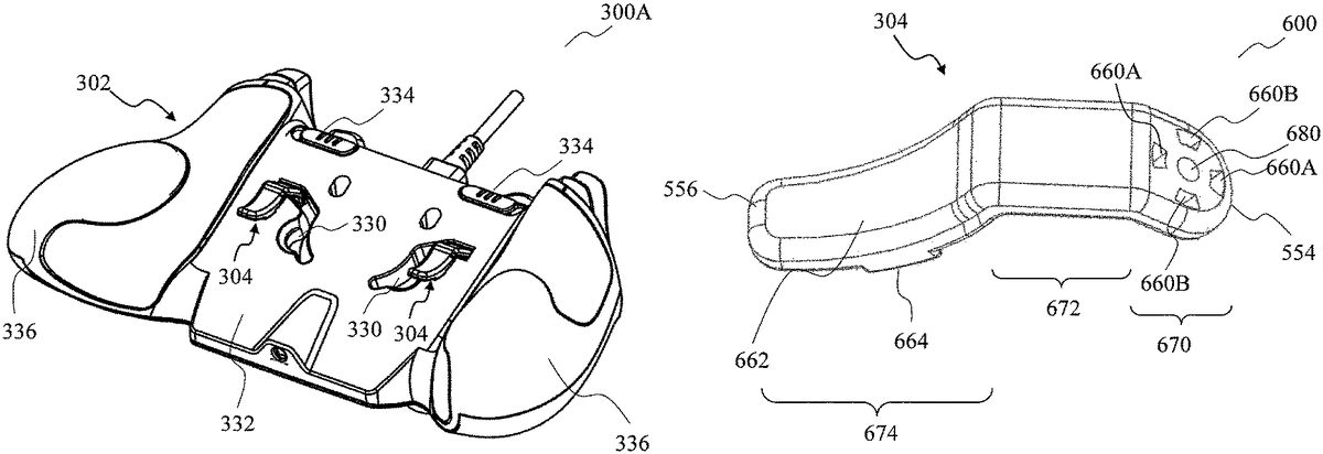
FIG. 3Ashows a perspective view300A of a game controller according to various embodiments, when the trigger buttons304are arranged in the operable position. The operable position may also be referred herein as the first position. The game controller shown inFIG. 3may be the game controller100or the game controller200, and the trigger button304may be identical to, or similar to the trigger button104. The game controller may include a housing302. The housing302may enclose the internal components of the game controller. The housing302may include curved surfaces336on two ends of the housing. A user of the game controller may grip the game controller at the curved surfaces336. The curved surfaces may be covered at least partially with a non-slip material, such as rubber or silicone to provide better grip for the user's hands. The surface shown in the perspective view300A may be an underside, also referred as a rear surface or a back surface332of the housing302. The game controller may include a plurality of control buttons on a front surface of the housing302. The front surface opposes the back surface332. The front surface is hidden in the perspective view300A. The game controller may include at least one trigger button304. While the embodiment illustrated inFIG. 3Ashows a pair of trigger buttons304positioned on the back surface332, a game controller may include one or two or more trigger buttons304. The trigger button304may also be arranged on the front surface of the housing302or on any other surface of the housing302. The housing302may include a cavity or a depression330on the back surface332. The trigger button304may be releasably coupled to a pivotable member (not shown) which may be arranged within the depression330. The trigger button304may include a lever or an at least substantially flat and elongated handle, and may be coupled at one end to the housing302. The trigger button304may be depressed towards the back surface332, or in other words, pushed towards the back surface332. When the trigger button304is depressed, the trigger button304may pivot about the one end. The game controller may also include a slide button334may be part of a release mechanism that may be operable to unlock the trigger button304from the pivotable member. When the trigger button is unlocked, the trigger button304may be rotatable to a second position. Alternatively, the slide button334may also be a control button used for providing user inputs. While the slide button334is shown as being arranged on the back surface332, it would be understood that the slide button may be arranged elsewhere on the housing302. Yet alternatively, bumpers instead of slide buttons may be arranged at the positions whereFIG. 3Ashows that the slide buttons334are positioned.
FIG. 3Bshows a perspective view300B of the game controller ofFIG. 3A, when the trigger buttons304are arranged in the retracted position. The retracted position is also referred herein as the second position. The trigger buttons304are shown as being retracted into depressions330. The trigger button304may be rotated from the operable position shown inFIG. 3Ato the retracted position shown inFIG. 3B. The trigger button304may be rotated by at least substantially 90° to move from the operable position to the retracted position. The rotation of the trigger button304may be about a rotation axis that is at least substantially perpendicular to the direction that the trigger button304is depressible. The rotation axis may be at least substantially parallel to the back surface332. The permissible rotation angle may be at most 90 degrees in either the clockwise direction or the counter-clockwise direction. The permissible rotation angle may be limited by the back surface332rather than by a rotation mechanism of the trigger button304. For example, one end of the trigger button304may be coupled to the housing302. The one end may be coupled to the housing302from within the depression330. The depression330may be shaped to have a wall that limits the trigger button304from being rotated towards a particular direction, as the trigger button may abut the wall when it is being rotated towards the particular direction. The depression330may be shaped to accommodate the trigger button304, when the trigger button304is rotated in a desired direction. In the example shown inFIG. 3B, the depression330A is shaped to accommodate the trigger button304when the trigger button304is rotated towards the back surface332in a clockwise direction (from the perspective of a user viewing the back surface332).
FIG. 4shows a cross-sectional view400of a game controller according to various embodiments. The game controller is shown in an inverted position such that the back surface332of the housing302is shown as being above the front surface446of the housing302. In a normal usage of the game controller, the user will be facing the front surface446. The game controller may be designed for the user to grip the game controller by its two ends, with the user's thumbs being placed on the front surface446while the user's fingers may be placed on the back surface332. A plurality of control buttons may be provided on the front surface446. The plurality of control buttons may include at least one of a thumb stick440, a direction pad (D-pad), a bumper or a key pad. The thumb stick440may also be referred herein as a joystick.FIG. 4also shows a plurality of buttons442which may be one of the direction pad, the bumper or the key pad. The buttons442may also be face buttons. The buttons442may be depressible in a direction that is towards the front surface446. A trigger button304may be arranged at the back surface332. The trigger button304may be coupled to a pivotable member770. The trigger button304and the pivotable member770may be pivotable about a pivoting axis. A rotation axis pin450may be anchored or coupled to the pivotable member770. The rotation axis pin450may be at least partially fitted through a receiving hole in the trigger button304and another receiving hole in the pivotable member770. The trigger button304may rotate from the first position to the second position by rotating about the rotation axis defined by the rotation axis pin450. The pivotable member770may engage the trigger button304such that the trigger button304pivots in tandem with the pivotable member770. The rotation axis pin450may hold a compression spring. The rotation axis pin450may be an insert molded pin, fabricated out of a metallic material such as stainless steel. The rotation axis pin450may be fabricated as a single part from a molding machine. The rotation axis pin450may hold the trigger304to its stationary position in both the first position and the second position. The compression spring may be threaded through the rotation axis pin450. The compression spring may push the trigger button304towards the pivotable member770. When the trigger button304is rotated between the first position and the second position, the compression spring may be compressed temporarily, so as to allow the trigger button304to disengage temporarily from the pivotable member770. When the compression spring rebounds following the temporary compression, the trigger button304may impact the pivotable member770, thereby providing at least one of a tactile feel on the trigger button304or an audible sound. The tactile feel or the audible sound may be useful as a form of feedback for the user to know that the trigger button304is locked into position. The pivotable member770may also be coupled to a further compression spring which may bias the pivotable member770to a level position as shown inFIG. 4. When the trigger button304is depressed, the pivotable member770may pivot and thereby compress the further compression spring. When the external depressing force on the trigger button304is removed, the further compression spring may release the elastic energy stored therein to push the pivotable member770back to its default level position.
FIG. 5shows a close-up view500of the trigger button304on a game controller according to various embodiments. The close-up view500shows the trigger button304in the first position. The trigger button304may be rotated in the direction indicated by the curved arrow550, about the rotation axis552, to arrive at the second position. At the second position, the trigger button304may be positioned inside the depression330. The depression330may be large enough to store the trigger button304. In addition, the depression330may include a concave space558for a user's finger to be inserted into the depression330, so as to contact the trigger button304. This may allow the user to manually pull the trigger button304out of the depression330. The trigger button304may also be extended out from the depression330, by actuating a release button. The release button may be coupled to a compression spring that biases the trigger button304towards the pivotable member770. When the release button is actuated, the compression spring may be compressed so that the trigger button304is unlocked from the pivotable member770. A further compression spring may push the trigger button304out of the depression330. The rotation axis552may be at least substantially parallel to a plane defined by the back surface332. The trigger button304may be depressed or pivoted by exerting a force on a second end556of the trigger button304, in the direction560. The direction560may be at least substantially perpendicular to the rotation axis552. The second end556may oppose a first end554. The trigger button304may be coupled to the pivotable member770at the first end554.
FIG. 6shows an illustration600of a trigger button304according to various embodiments. The trigger button304may include the first end554and the second end556. The trigger button304may include a first segment670, a second segment672and a third segment674. The first segment670may include the first end554. The first segment670may include an at least substantially planar surface. The first segment670may include at least two sets of openings or holes on the at least substantially planar surface. The first segment670may also include an at least substantially circular through hole680for receiving the rotation axis pin450. The embodiment shown inFIG. 6includes a first set of holes660A and a second set of holes660B. Each set of holes may include at least one hole. The second segment672may extend from the first segment670. The second segment672may also include a surface that is at least substantially planar. The second segment672may be arranged at an angle with respect to the first segment670. The angle may be an obtuse angle. The third segment674may extend from the second segment672. The third segment674may include the second end556. The third segment674may be shaped to receive a user's finger. For example, the third segment674may be curved, such as in a concave manner, or include a curved surface662. The third segment674may include a contact platform664. The contact platform664may activate the switch of the game controller when the trigger button304is depressed. The contact platform664may activate the switch by either directly contacting the switch or by contacting an actuator which then activates the switch. The contact platform664may protrude out of a bottom surface of the trigger button304. The trigger button304may be fabricated by die casting aluminum.
FIG. 7shows an illustration700of a pivotable member770according to various embodiments. The pivotable member770may be part of the locking mechanism106and may be configured to engage the trigger button304. The pivotable member770may include a first arm780and a second arm782. The first arm780may be at least substantially perpendicular to the second arm782. The first arm780may have a contact surface784. At least one bump or protrusion774may be formed on the contact surface784. When the game controller is in an assembled state, the contact surface784may abut the first segment670of the trigger button304. The protrusions774may be shaped to fit in the holes660A or660B. The holes660A or660B may fit over the protrusions774, so that the trigger button304cannot freely rotate between the first position and the second position. In other words, the locking mechanism106of the game controller may include the protrusion774and the holes660A and660B. When the trigger button304is at the first position, the first set of holes660A may fit over protrusions774of the pivotable member770. When the trigger button304is at the second position, the second set of holes660B may fit over the protrusions774of the pivotable member770. In the process of inserting the protrusion774into the hole660A or660B, at least one of the protrusion774or the hole may be transiently deformed until the protrusion774is fully inserted through the hole. When released from the transient deformation, the protrusion774or the hole may produce an audible sound, like a “click” sound. The sound may indicate to the user that the trigger button is locked in position. The release from the transient deformation may also provide a tactile feel to the user as the material of either the protrusion774or the hole rebounds to its original shape. A receiving hole790may be formed through the contact surface784, to receive the rotation axis pin450. The second arm782may serve to support an assembly of the rotation axis pin450, as shown inFIG. 4. The first arm780may include an extension786. The extension786may be at least substantially perpendicular to the contact surface784. The extension786may include a through hole772for holding a pivot shaft. The pivotable member770may pivot about the pivot shaft. The extension786may include a holder776for holding a compression spring. The compression spring held by the holder776may bias the pivotable member770towards a level position for supporting the trigger button304in an undepressed position. The pivotable member770may be an aluminum die cast bracket. The pivotable member770may be configured to support or hold the rotation axis pin450.
According to various embodiments, the pivotable member770may include holes while the trigger button304may include a protrusion. The protrusion may be shaped to fit in the holes.
FIG. 8Ashows a cross-sectional view800A of the operating mechanism of a trigger button304according to various embodiments. The cross-sectional view800A shows the trigger button304in the first position, i.e. the operable position. The main board880, also referred herein as a circuit board, may be arranged under the trigger button304, the pivotable member770and the rotation axis pin450. A switch808may be coupled to the main board880. When the electrical switch808is activated, an electrical signal may be transmitted to the main board880. The electrical signal may be converted into a message for communication with a computing device or gaming console. The electrical switch808may be the switch208. An actuator886may be arranged adjacent to the electrical switch808. The actuator886may be fabricated from a polymer material such as ABS plastic. The rotation axis pin450may be insert molded to the actuator886. The trigger button304may rotate about the rotation axis pin450. By being threaded through the through hole680of the trigger button304, the rotation axis pin450may hold the trigger button304in place in the game controller. The trigger button304may extend out of the housing of the game controller. In its default state, i.e. undepressed state when no external force is exerted on the trigger button304, the contact platform664does not contact the actuator886and the switch808. A first biasing member882which may be a compression spring, may bias the trigger button towards being undepressed. A second biasing member884may also be compression spring. The second biasing member884may bias the trigger button304to abut the pivotable member770.
FIG. 8Bshows a cross-sectional view800B which is the cross-sectional view800A annotated with arrows indicating movements in the operating mechanism of the trigger button304when the trigger button304is depressed. The trigger button304may be depressible at least substantially towards the housing, i.e. in the direction890. When the game controller is held upright, the direction890may be towards the user, i.e. upwards. When the trigger button304is depressed, the rotation axis pin450moves in the direction892towards the pivotable member770. By virtue of being locked to the trigger button304, the pivotable member770pivots about its pivot axis in the direction894. The pivot axis of the pivotable member770may be defined by the pivot shaft inserted into the through hole772. When the trigger button304pivots, the contact platform664may impact or activate the actuator886. The actuator886may also move together with the rotation axis pin450towards the direction892. The actuator886may thereby activate the electrical switch808. The actuator886may move towards the switch808in a direction896. The actuator886may serve as the main body that actuates the switch808when the trigger button304is depressed. The actuator886may be coupled to the pivotable member770and the trigger button304through the rotation axis pin450. Throughout the pivoting of the trigger button304, the trigger button304may remain stationary relative to the pivotable member770. When the trigger button304is contacting the electrical switch808, the first biasing member882may be compressed.
FIG. 9shows an illustration900of the operating mechanism of a trigger button904according to various embodiments. The operating mechanism may be similar to the operating mechanism ofFIG. 8A, but may further include a casing990coupled to the actuator886. The trigger button904may be the trigger button104while the locking mechanism may be the locking mechanism106. The trigger button904may be similar to the trigger button304in that it may also include a plurality of holes960for engaging with a corresponding plurality of protrusions994. The plurality of holes960and the plurality of protrusions994may be part of the locking mechanism. The plurality of protrusions994may be provided on the casing990. The plurality of protrusions may include at least one spring-loaded lock pin950. In addition to providing the protrusions994for locking the trigger button904, the casing990may also function as a holder to the trigger button904. The trigger button904may be couplable to each of the bracket970and the casing990. The trigger button904may be sandwiched in between the casing990and the bracket970. The casing990may include the rotating axis pin450. The protrusions994may be arranged at a peripheral boundary of the rotating axis pin450. The casing990may be fabricated out of a self-lubricating material, such as polyocymethylene (POM). A bracket970, similar to the pivotable member770except that it may not include any protrusion774, may be provided. The bracket970may include a receiving hole780for receiving the rotating axis pin450.
FIG. 10shows a cross-sectional view1000of the operating mechanism of a trigger button904according to various embodiments. The operating mechanism may be similar to the operating mechanism ofFIG. 8A, but may further include the casing990and the lock pin950. A spring1010may be fitted onto the lock pin950, to bias the lock pin950against the trigger button. The lock pin950may abut the first segment670of the trigger button904. The first segment670may include a notch on the surface facing the lock pin950and the lock pin950may fit into the notch when the lock pin950abuts the trigger button904. The notch may be one of the holes960. The lock pin950may be one of the protrusions994. When the trigger button904is being rotated, the protrusions994on the casing990may disengage from the holes960on the trigger button904, and the trigger button904may displace slightly away from the casing990. The spring1010may expand and push the lock pin950towards the notch, thereby producing a snap lock effect. A ‘click’ sound may also be generated in the snap lock effect. The snap lock effect may provide at least one of a tactile feedback or an audio feedback to the user, so that the user knows that the trigger button904is unlocked from the first position or the second position. When the trigger button904locks into the first position or the second position, the trigger button904may displace slightly towards the casing990and again, the lock pin950may be pushed into the notch, thereby producing the snap lock effect. The user may thereby be informed that the trigger button904has been locked into the first position or the second position.
The following examples pertain to further embodiments.
Example 1 is a game controller including a trigger button rotatable between a first position and a second position by rotating about a rotation axis, the trigger button being depressible in a direction to activate a switch when the trigger button is in the first position, wherein the direction is at least substantially perpendicular to the rotation axis; and a locking mechanism configured to constrain rotation of the trigger button when the trigger button is in the first position, and further configured to constrain rotation of the trigger button when the trigger button is in the second position.
In example 2, the subject-matter of example 1 can optionally include a housing.
In example 3, the subject-matter of example 2 can optionally include that the housing comprises a depression, the trigger button being retracted into the depression when the trigger button is in the second position.
In example 4, the subject-matter of example 2 or example 3 can optionally include that the trigger button extends out of the housing in the first position.
In example 5, the subject-matter of any one of examples 2 to 4 can optionally include that the direction is at least substantially towards the housing.
In example 6, the subject-matter of any one of examples 2 to 5 can optionally include a plurality of control buttons on a front surface of the housing.
In example 7, the subject-matter of example 6 can optionally include that the front surface opposes a back surface of the housing, wherein the trigger button is positioned on the back surface.
In example 8, the subject-matter of example 6 or example 7 can optionally include that the plurality of control buttons comprises at least one of a thumb stick, a direction pad, a bumper or a keypad.
In example 9, the subject-matter of any one of examples 1 to 8 can optionally include that the trigger button is biased towards being undepressed when the trigger button is in the first position.
In example 10, the subject-matter of any one of examples 1 to 9 can optionally include that the trigger button is pivotable to activate a switch.
In example 11, the subject-matter of any one of examples 1 to 10 can optionally include that the trigger button comprises a lever.
In example 12, the subject-matter of example 11 can optionally include that the lever comprises a concave segment shaped to receive a user's finger.
In example 13, the subject-matter of any one of examples 1 to 12 can optionally include that the locking mechanism comprises a pivotable member configured to engage the trigger button.
In example 14, the subject-matter of example 13 can optionally include that the trigger button is pivotable by pivoting the pivotable member, the trigger button being stationary relative to the pivotable member.
In example 15, the subject-matter of example 13 or example 14 can optionally include that the pivotable member comprises a protrusion and the trigger button comprises a hole, the protrusion shaped to fit in the hole.
In example 16, the subject-matter of example 15 can optionally include that the locking mechanism comprises the protrusion and the hole.
In example 17, the subject-matter of example 15 or example 16 can optionally include that at least one of the protrusion or the trigger button is transiently deformed when the protrusion is inserted into the hole.
In example 18, the subject-matter of example 17 can optionally include that the at least one of the protrusion or the trigger button produces an audible sound when released from the transient deformation.
In example 19, the subject-matter of any one of examples 15 to 18 can optionally include that the trigger button comprises a first hole and a second hole, wherein the protrusion fits into the first hole when the trigger button is in the first position, and wherein the protrusion fits into the second hole when the trigger button is in the second position.
In example 20, the subject-matter of example 13 or example 14 can optionally include that the pivotable member comprises a hole and the trigger button comprises a protrusion, the protrusion shaped to fit in the hole.
In example 21, the subject-matter of any one of examples 13 to 20 can optionally include that the trigger button is biased to abut the pivotable member.
In example 22, the subject-matter of example 21 can optionally include that the trigger button is biased to abut the pivotable member by a compression spring.
In example 23, the subject-matter of example 22 can optionally include that rotation of the trigger button compresses the compression spring.
In example 24, the subject-matter of example 23 can optionally include that the trigger button impacts the pivotable member when the compressed compression spring rebounds.
In example 25, the subject-matter of example 24 can optionally include that the impact provides at least one of a tactile feel on the trigger button or an audible sound.
In example 26, the subject-matter of any one of examples 1 to 25 can optionally include that the depression is shaped to accommodate the trigger button.
In example 27, the subject-matter of example 26 can optionally include that the depression comprises a concave space for a user's finger to contact the trigger button when the trigger button is in the second position.
In example 28, the subject-matter of any one of examples 1 to 27 can optionally include that the trigger button rotates through an angle at least substantially equal to 90° between the first position and the second position.
In example 29, the subject-matter of any one of examples 1 to 28 can optionally include the switch.
In example 30, the subject-matter of any one of examples 1 to 29 can optionally include a user interface configured to receive user inputs for programming a function of the trigger button.
While embodiments of the invention have been particularly shown, and described with reference to specific embodiments, it should be understood by those skilled in the art that various changes in form and detail may be made therein without departing from the spirit and scope of the invention as defined by the appended claims. The scope of the invention is thus indicated by the appended claims and all changes which come within the meaning and range of equivalency of the claims are therefore intended to be embraced. It will be appreciated that common numerals, used in the relevant drawings, refer to components that serve a similar or the same purpose.
Claims
- A game controller comprising: a trigger button rotatable between a first position and a second position by rotating about a rotation axis, the trigger button being depressible in a direction to activate a switch when the trigger button is in the first position, wherein the direction is at least substantially perpendicular to the rotation axis;a locking mechanism configured to constrain rotation of the trigger button when the trigger button is in the first position, and further configured to constrain rotation of the trigger button when the trigger button is in the second position, wherein the trigger button comprises a first hole and a second hole, and wherein the locking mechanism comprises a protrusion shaped to fit into the first hole when the trigger button is in the first position, and wherein the protrusion is shaped to fit into the second hole when the trigger button is in the second position;a housing;wherein the housing comprises a depression, the trigger button being retracted into the depression when the trigger button is in the second position.
- The game controller of claim 1 , wherein the trigger button extends out of the housing in the first position.
- The game controller of claim 1 , further comprising: a plurality of control buttons on a front surface of the housing.
- The game controller of claim 3 , wherein the front surface opposes a back surface of the housing, wherein the trigger button is positioned on the back surface.
- The game controller of claim 1 , wherein the trigger button is biased towards being undepressed when the trigger button is in the first position.
- The game controller of claim 1 , wherein the trigger button is pivotable to activate a switch.
- The game controller of claim 1 , wherein the trigger button comprises a lever.
- The game controller of claim 7 , wherein the lever comprises a concave segment shaped to receive a user's finger.
- The game controller of claim 1 , wherein the locking mechanism comprises a pivotable member configured to engage the trigger button.
- The game controller of claim 9 , wherein the trigger button is biased to abut the pivotable member.
- The game controller of claim 10 , wherein the trigger button is biased to abut the pivotable member by a compression spring.
- The game controller of claim 11 , wherein rotation of the trigger button compresses the compression spring.
- The game controller of claim 1 , wherein the depression is shaped to accommodate the trigger button.
- The game controller of claim 13 , wherein the depression comprises a concave space for a user's finger to contact the trigger button when the trigger button is in the second position.
- The game controller of claim 1 , wherein the trigger button rotates through an angle at least substantially equal to 90° between the first position and the second position.
- The game controller of claim 1 , further comprising: the switch.
- The game controller of claim 1 , further comprising a user interface configured to receive user inputs for programming a function of the trigger button.
- The game controller of claim 1 , further comprising a user interface configured to receive user inputs for programming a function of the trigger button.
Disclaimer: Data collected from the USPTO and may be malformed, incomplete, and/or otherwise inaccurate.