U.S. Pat. No. 10,661,163
VIDEO GAME WITH HAPTIC SIGNAL THAT IS DISABLED BASED ON LOSING CONTACT WITH A SURFACE
AssigneeNINTENDO CO., LTD.
Issue DateMay 23, 2018
Illustrative Figure
Abstract
Provided is an example system in which a vibrator continues to vibrate when a player character is in contact with a ground object in a virtual space. When the player character performs a jumping motion in the virtual space according to an operation performed by a player, the player character leaves the ground object. While the player character is performing a jumping motion, the vibration of the vibrator is temporarily stopped. When the player character drops on the ground object again, the vibration of the vibrator is resumed.
Description
DETAILED DESCRIPTION OF NON-LIMITING EXAMPLE EMBODIMENTS A game system according to an example of an exemplary embodiment will now be described. An example of a game system1according to the exemplary embodiment includes a main body apparatus (an information processing apparatus that functions as a game apparatus main body in the exemplary embodiment)2, a left controller3, and a right controller4. Each of the left and right controllers3and4is attachable to and detachable from the main body apparatus2. That is, the game system1can be used as a unified apparatus obtained by attaching each of the left and right controllers3and4to the main body apparatus2. Further, in the game system1, the main body apparatus2, the left controller3, and the right controller4can also be used as separate bodies (seeFIG. 2). In the description that follows, a hardware configuration of the game system1according to the exemplary embodiment is described, followed by a description of the control of the game system1according to the exemplary embodiment. FIG. 1is a diagram showing an example of the state in which the left and right controllers3and4are attached to the main body apparatus2. As shown inFIG. 1, each of the left and right controllers3and4is attached to and unified with the main body apparatus2. The main body apparatus2is for performing various processes (e.g., game processes) in the game system1. The main body apparatus2includes a display12. Each of the left and right controllers3and4includes operating portions with which a user provides inputs. FIG. 2is a diagram showing an example of the state in which each of the left and right controllers3and4is detached from the main body apparatus2. As shown inFIGS. 1 and 2, the left and right controllers3and4are attachable to and detachable from the main body apparatus2. It should be noted that the left and right controllers3and4may also be hereinafter collectively referred to as “the controller” ...
DETAILED DESCRIPTION OF NON-LIMITING EXAMPLE EMBODIMENTS
A game system according to an example of an exemplary embodiment will now be described. An example of a game system1according to the exemplary embodiment includes a main body apparatus (an information processing apparatus that functions as a game apparatus main body in the exemplary embodiment)2, a left controller3, and a right controller4. Each of the left and right controllers3and4is attachable to and detachable from the main body apparatus2. That is, the game system1can be used as a unified apparatus obtained by attaching each of the left and right controllers3and4to the main body apparatus2. Further, in the game system1, the main body apparatus2, the left controller3, and the right controller4can also be used as separate bodies (seeFIG. 2). In the description that follows, a hardware configuration of the game system1according to the exemplary embodiment is described, followed by a description of the control of the game system1according to the exemplary embodiment.
FIG. 1is a diagram showing an example of the state in which the left and right controllers3and4are attached to the main body apparatus2. As shown inFIG. 1, each of the left and right controllers3and4is attached to and unified with the main body apparatus2. The main body apparatus2is for performing various processes (e.g., game processes) in the game system1. The main body apparatus2includes a display12. Each of the left and right controllers3and4includes operating portions with which a user provides inputs.
FIG. 2is a diagram showing an example of the state in which each of the left and right controllers3and4is detached from the main body apparatus2. As shown inFIGS. 1 and 2, the left and right controllers3and4are attachable to and detachable from the main body apparatus2. It should be noted that the left and right controllers3and4may also be hereinafter collectively referred to as “the controller” or “the controllers.”
FIG. 3is a diagram having six orthogonal views showing an example of the main body apparatus2. As shown inFIG. 3, the main body apparatus2includes an approximately plate-shaped housing11. In the exemplary embodiment, a main surface (in other words, a surface on a front side, i.e., a surface on which the display12is provided) of the housing11has a generally rectangular shape.
It should be noted that the housing11may have any suitable shape and size. As an example, the housing11may be of a portable size. Further, the main body apparatus2alone or the unified apparatus obtained by attaching the left and right controllers3and4to the main body apparatus2may function as a mobile apparatus. The main body apparatus2or the unified apparatus may also function as a handheld apparatus or a portable apparatus.
As shown inFIG. 3, the main body apparatus2includes the display12, which is provided on the main surface of the housing11. The display12displays an image generated by the main body apparatus2. In the exemplary embodiment, the display12is a liquid crystal display device (LCD). The display12, however, may be any type of display device.
Further, the main body apparatus2includes a touch panel13on a screen of the display12. In the exemplary embodiment, the touch panel13is of a type that allows a multi-touch input (e.g., a capacitive type). The touch panel13, however, may be of any type. For example, the touch panel13may be of a type that allows a single-touch input (e.g., a resistive type).
The main body apparatus2includes speakers (i.e., speakers88shown inFIG. 6) within the housing11. As shown inFIG. 3, speaker holes11aand11bare formed in the main surface of the housing11. Then, output sounds of the speakers88are output through the speaker holes11aand11b.
Further, the main body apparatus2includes a left terminal17for allowing the main body apparatus2to perform wired communication with the left controller3, and a right terminal21for allowing the main body apparatus2to perform wired communication with the right controller4.
As shown inFIG. 3, the main body apparatus2includes a slot23. The slot23is provided in an upper side surface of the housing11. The slot23is so shaped as to allow a predetermined type of storage medium to be loaded in the slot23. The predetermined type of storage medium is, for example, a dedicated storage medium (e.g., a dedicated memory card) to the game system1and an information processing apparatus of the same type as that of the game system1. The predetermined type of storage medium is used to store, for example, data (e.g., saved data of an application or the like) used by the main body apparatus2and/or a program (e.g., a program for an application or the like) executed by the main body apparatus2. Further, the main body apparatus2includes a power button28.
The main body apparatus2includes a lower terminal27. The lower terminal27is for allowing the main body apparatus2to communicate with a cradle. In the exemplary embodiment, the lower terminal27is a USB connector (more specifically, a female connector). Further, when the unified apparatus or the main body apparatus2alone is mounted on the cradle, the game system1can display on a stationary monitor an image generated by and output from the main body apparatus2. Further, in the exemplary embodiment, the cradle has the function of charging the unified apparatus or the main body apparatus2alone mounted on the cradle. Further, the cradle also functions as a hub device (specifically, a USB hub).
FIG. 4is a diagram having six orthogonal views showing an example of the left controller3. As shown inFIG. 4, the left controller3includes a housing31. In the exemplary embodiment, the housing31is longer than it is wide, i.e., is shaped to be long in the vertical direction (i.e., the y-axis direction shown inFIGS. 1 and 4). In the state in which the left controller3is detached from the main body apparatus2, the left controller3can also be held in the portrait orientation. The housing31has such a shape and size that when held in the portrait orientation, the housing31can be held by one hand, particularly the left hand. Further, the left controller3can also be held in the landscape orientation. When held in the landscape orientation, the left controller3may be held by both hands.
The left controller3includes an analog stick32. As shown inFIG. 4, the analog stick32is provided on a main surface of the housing31. The analog stick32can be used as a direction input section with which a direction can be input. The user tilts the analog stick32and thereby can input a direction corresponding to the direction of the tilt (and input a magnitude corresponding to the angle of the tilt). It should be noted that the left controller3may include a directional pad, a slide stick that allows a slide input, or the like as the direction input section, instead of the analog stick. Further, in the exemplary embodiment, it is possible to provide an input by pressing down the analog stick32.
The left controller3includes various operation buttons. The left controller3includes four operation buttons33to36(specifically, a “right” button33, a “down” button34, an “up” button35, and a “left” button36) on the main surface of the housing31. Further, the left controller3includes a record button37and a “−” (minus) button47. The left controller3includes a first L-button38and a ZL-button39in an upper left portion of a side surface of the housing31. Further, the left controller3includes a second L-button43and a second R-button44, on the side surface of the housing31on which the left controller3is attached to the main body apparatus2. These operation buttons are used to give instructions depending on various programs (e.g., an OS program and an application program) executed by the main body apparatus2.
Further, the left controller3includes a terminal42for allowing the left controller3to perform wired communication with the main body apparatus2.
FIG. 5is a diagram having six orthogonal views showing an example of the right controller4. As shown inFIG. 5, the right controller4includes a housing51. In the exemplary embodiment, the housing51is longer than it is wide, i.e., is shaped to be long in the vertical direction. In the state in which the right controller4is detached from the main body apparatus2, the right controller4can also be held in the portrait orientation. The housing51has such a shape and size that when held in the portrait orientation, the housing51can be held by one hand, particularly the right hand. Further, the right controller4can also be held in the landscape orientation. When held in the landscape orientation, the right controller4may be held by both hands.
As with the left controller3, the right controller4includes an analog stick52as a direction input section. In the exemplary embodiment, the analog stick52has the same configuration as that of the analog stick32of the left controller3. Further, the right controller4may include a directional pad, a slide stick that allows a slide input, or the like, instead of the analog stick. Further, as with the left controller3, the right controller4includes four operation buttons53to56(specifically, an A-button53, a B-button54, an X-button55, and a Y-button56). Further, the right controller4includes a “+” (plus) button57and a home button58. Further, the right controller4includes a first R-button60and a ZR-button61in an upper right portion of a side surface of the housing51. Further, as with the left controller3, the right controller4includes a second L-button65and a second R-button66.
Further, the right controller4includes a terminal64for allowing the right controller4to perform wired communication with the main body apparatus2.
FIG. 6is a block diagram showing an example of an internal configuration of the main body apparatus2. The main body apparatus2includes components81to91,97, and98shown inFIG. 6in addition to the components shown inFIG. 3. Some of the components81to98may be implemented as electronic parts on an electronic circuit board, which is accommodated in the housing11.
The main body apparatus2includes a processor81. The processor81is an information processing section for executing various types of information processing to be executed by the main body apparatus2. For example, the CPU81may be composed only of a central processing unit (CPU), or may be a system-on-a-chip (SoC) having a plurality of functions such as a CPU function, a graphics processing unit (GPU) function, and the like. The processor81executes an information processing program (e.g., a game program) stored in a storage section (specifically, an internal storage medium such as a flash memory84, an external storage medium that is loaded in the slot23, or the like), thereby performing the various types of information processing.
The main body apparatus2includes a flash memory84and a dynamic random access memory (DRAM)85as examples of internal storage media built in the main body apparatus2. The flash memory84and the DRAM85are coupled to the CPU81. The flash memory84is mainly used to store various data (or programs) to be saved in the main body apparatus2. The DRAM85is used to temporarily store various data used in information processing.
The main body apparatus2includes a slot interface (hereinafter abbreviated to “I/F”)91. The slot I/F91is coupled to the processor81. The slot I/F91is coupled to the slot23, and reads and writes data from and to the predetermined type of storage medium (e.g., a dedicated memory card) loaded in the slot23, in accordance with instructions from the processor81.
The processor81appropriately reads and writes data from and to the flash memory84, the DRAM85, and each of the above storage media, thereby performing the above information processing.
The main body apparatus2includes a network communication section82. The network communication section82is coupled to the processor81. The network communication section82communicates (specifically, through wireless communication) with an external apparatus via a network. In the exemplary embodiment, as a first communication form, the network communication section82connects to a wireless LAN and communicates with an external apparatus, using a method compliant with the Wi-Fi standard. Further, as a second communication form, the network communication section82wirelessly communicates with another main body apparatus2of the same type, using a predetermined communication method (e.g., communication based on a unique protocol or infrared light communication). It should be noted that the wireless communication in the above second communication form achieves the function of enabling so-called “local communication” in which the main body apparatus2can wirelessly communicate with another main body apparatus2located in a closed local network area, and the plurality of main body apparatuses2directly communicate with each other to exchange data.
The main body apparatus2includes a controller communication section83. The controller communication section83is coupled to the processor81. The controller communication section83wirelessly communicates with the left controller3and/or the right controller4. The main body apparatus2may communicate with the left and right controllers3and4using any suitable communication method. In the exemplary embodiment, the controller communication section83performs communication with the left and right controllers3and4in accordance with the Bluetooth (registered trademark) standard.
The processor81is coupled to the left terminal17, the right terminal21, and the lower terminal27. When performing wired communication with the left controller3, the processor81transmits data to the left controller3via the left terminal17and also receives operation data from the left controller3via the left terminal17. Further, when performing wired communication with the right controller4, the processor81transmits data to the right controller4via the right terminal21and also receives operation data from the right controller4via the right terminal21. Further, when communicating with the cradle, the processor81transmits data to the cradle via the lower terminal27. As described above, in the exemplary embodiment, the main body apparatus2can perform both wired communication and wireless communication with each of the left and right controllers3and4. Further, when the unified apparatus obtained by attaching the left and right controllers3and4to the main body apparatus2or the main body apparatus2alone is attached to the cradle, the main body apparatus2can output data (e.g., image data or sound data) to a stationary monitor or the like via the cradle.
Here, the main body apparatus2can communicate with a plurality of left controllers3simultaneously (or in parallel). Further, the main body apparatus2can communicate with a plurality of right controllers4simultaneously (or in parallel). Thus, a plurality of users can simultaneously provide inputs to the main body apparatus2, each using a set of the left and right controllers3and4. As an example, a first user can provide an input to the main body apparatus2using a first set of the left and right controllers3and4, and at the same time, a second user can provide an input to the main body apparatus2using a second set of the left and right controllers3and4.
The main body apparatus2includes a touch panel controller86that is a circuit for controlling the touch panel13. The touch panel controller86is coupled between the touch panel13and the processor81. Based on a signal from the touch panel13, the touch panel controller86generates, for example, data indicating a position where a touch input has been performed. Then, the touch panel controller86outputs the data to the processor81.
Further, the display12is coupled to the processor81. The processor81displays, on the display12, a generated image (e.g., an image generated by executing the above information processing) and/or an externally acquired image.
The main body apparatus2includes a codec circuit87and speakers (specifically, a left speaker and a right speaker)88. The codec circuit87is coupled to the speakers88and an audio input/output terminal25and also coupled to the processor81. The codec circuit87is for controlling the input and output of audio data to and from the speakers88and the sound input/output terminal25.
Further, the main body apparatus2includes an acceleration sensor89. In the exemplary embodiment, the acceleration sensor89detects the magnitudes of accelerations along predetermined three axial (e.g., x-, y-, and z-axes shown inFIG. 1) directions. It should be noted that the acceleration sensor89may detect an acceleration along one axial direction or accelerations along two axial directions.
Further, the main body apparatus2includes an angular velocity sensor90. In the exemplary embodiment, the angular velocity sensor90detects angular velocities about predetermined three axes (e.g., the x-, y-, and z-axes shown inFIG. 2). It should be noted that the angular velocity sensor90may detect an angular velocity about one axis or angular velocities about two axes.
The acceleration sensor89and the angular velocity sensor90are coupled to the processor81, and the detection results of the acceleration sensor89and the angular velocity sensor90are output to the processor81. Based on the detection results of the acceleration sensor89and the angular velocity sensor90, the processor81can calculate information regarding a motion and/or orientation of the main body apparatus2.
The main body apparatus2includes a power control section97and a battery98. The power control section97is coupled to the battery98and the processor81. Further, although not shown, the power control section97is coupled to components of the main body apparatus2(specifically, components that receive power supplied from the battery98, the left terminal17, and the right terminal21). Based on a command from the processor81, the power control section97controls the supply of power from the battery98to each of the above components.
Further, the battery98is coupled to the lower terminal27. When an external charging device (e.g., the cradle) is connected to the lower terminal27, and power is supplied to the main body apparatus2via the lower terminal27, the battery98is charged with the supplied power.
FIG. 7is a block diagram showing examples of internal configurations of the main body apparatus2, the left controller3, and the right controller4. It should be noted that the details of the internal configuration of the main body apparatus2are shown inFIG. 6and therefore are not shown inFIG. 7.
The left controller3includes a communication control section101that communicates with the main body apparatus2. As shown inFIG. 7, the communication control section101is coupled to components including the terminal42. In the exemplary embodiment, the communication control section101can communicate with the main body apparatus2through both wired communication via the terminal42and wireless communication without via the terminal42. The communication control section101controls a communication method which is performed by the left controller3with respect to the main body apparatus2. That is, when the left controller3is attached to the main body apparatus2, the communication control section101communicates with the main body apparatus2via the terminal42. Further, when the left controller3is detached from the main body apparatus2, the communication control section101wirelessly communicates with the main body apparatus2(specifically, the controller communication section83). The wireless communication between the communication control section101and the controller communication section83is performed in accordance with the Bluetooth (registered trademark) standard, for example.
Further, the left controller3includes a memory102such as a flash memory. The communication control section101includes, for example, a microcomputer (or a microprocessor) and executes firmware stored in the memory102, thereby performing various processes.
The left controller3includes buttons103(specifically, the buttons33to39,43,44, and47). Further, the left controller3includes the analog stick (“stick” inFIG. 7)32. The buttons103and the analog stick32each output information regarding an operation performed on itself to the communication control section101repeatedly at appropriate timings.
The left controller3includes inertial sensors. Specifically, the left controller3includes an acceleration sensor104. Further, the left controller3includes an angular velocity sensor105. In the exemplary embodiment, the acceleration sensor104detects the magnitudes of accelerations along predetermined three axial (e.g., x-, y-, and z-axes shown inFIG. 5) directions. It should be noted that the acceleration sensor104may detect an acceleration along one axial direction or accelerations along two axial directions. Each of the acceleration sensor104and the angular velocity sensor105is coupled to the communication control section101. Then, the detection results of the acceleration sensor104and the angular velocity sensor105are output to the communication control section101repeatedly at appropriate timings.
The communication control section101acquires information regarding an input (specifically, information regarding an operation or the detection result of a sensor) from each of input sections (specifically, the buttons103, the analog stick32, and the sensors104and105). The communication control section101transmits operation data including the acquired information (or information acquired by performing predetermined processing on the acquired information) to the main body apparatus2. It should be noted that the operation data is transmitted repeatedly, once every predetermined time. It should be noted that the interval at which the information regarding an input is transmitted from each of the input sections to the main body apparatus2may or may not be the same.
The above operation data is transmitted to the main body apparatus2, whereby the main body apparatus2can acquire inputs provided to the left controller3. That is, the main body apparatus2can determine operations performed on the buttons103and the analog stick32based on the operation data. Further, the main body apparatus2can calculate information regarding a motion and/or orientation of the left controller3based on the operation data (specifically, the detection results of the acceleration sensor104and the angular velocity sensor105).
The left controller3includes a vibrator107for giving notification to the user by a vibration. In the exemplary embodiment, the vibrator107is controlled in accordance with a command from the main body apparatus2. That is, the communication control section101, when receiving the above command from the main body apparatus2, drives the vibrator107in accordance with the received command. Here, the left controller3includes a codec section106. The communication control section101, when receiving the above command, outputs a control signal corresponding to the command to the codec section106. The codec section106generates a drive signal for driving the vibrator107from the control signal received from the communication control section101, and outputs the drive signal to the vibrator107. The vibrator107is operated according to the drive signal.
More specifically, the vibrator107is a linear vibration motor. Unlike a typical motor that provides a rotary motion, the linear vibration motor is driven in a predetermined direction according to an input voltage and therefore can be vibrated at an amplitude and frequency corresponding to the waveform of the input voltage. In the exemplary embodiment, a vibration control signal transmitted from the main body apparatus2to the left controller3may be a digital signal representing a frequency and an amplitude every unit of time. In another exemplary embodiment, the main body apparatus2may transmit information indicating the waveform itself. However, if only the amplitude and the frequency are transmitted, the amount of communication data can be reduced. In order to further reduce the amount of data, only the differences between the current values of the amplitude and the frequency at each time and the previous values may be transmitted, instead of the current values themselves. In this case, the codec section106converts the digital signal indicating the values of the amplitude and the frequency acquired from the communication control section101into an analog voltage waveform, and inputs a voltage to the vibrator107according to the resulting waveform, thereby driving the vibrator107. Thus, the main body apparatus2changes the amplitude and frequency to be transmitted every unit of time, and thereby can control the amplitude and frequency with which the vibrator107is vibrated at each time. It should be noted that two or more different sets of amplitudes and frequencies indicating two or more waveforms may be transmitted from the main body apparatus2to the left controller3, instead of a single set of amplitudes and frequencies indicating a single waveform. In this case, the codec section106combines waveforms indicated by the plurality of sets of amplitudes and frequencies thus received, and thereby can generate a single voltage waveform for controlling the vibrator107.
The left controller3includes a power supply section108. In the exemplary embodiment, the power supply section108includes a battery and a power control circuit. Although not shown, the power control circuit is coupled to the battery and also coupled to components of the left controller3(specifically, components that receive power supplied from the battery).
As shown inFIG. 7, the right controller4includes a communication control section111that communicates with the main body apparatus2. Further, the right controller4includes a memory112that is coupled to the communication control section111. The communication control section111is coupled to components including the terminal64. The communication control section111and the memory112have functions similar to those of the communication control section101and the memory102, respectively, of the left controller3. Thus, the communication control section111can communicate with the main body apparatus2through both wired communication via the terminal64and wireless communication without via the terminal64(specifically, communication compliant with the Bluetooth (registered trademark) standard). The communication control section111controls a communication method that is performed by the right controller4with respect to the main body apparatus2.
The right controller4includes input sections similar to those of the left controller3. Specifically, the right controller4includes buttons113, an analog stick52, and inertial sensors (an acceleration sensor114and an angular velocity sensor115). These input sections have functions similar to those of the input sections of the left controller3and operate in manners similar to those of the input sections of the left controller3.
Further, the right controller4includes a vibrator117and a codec section116. The vibrator117and the codec section116operate in manners similar to those of the vibrator107and the codec section106, respectively, of the left controller3. That is, the communication control section111operates the vibrator117using the codec section116in accordance with a command from the main body apparatus2.
The right controller4includes a processing section121. The processing section121is coupled to the communication control section111.
The right controller4includes a power supply section118. The power supply section118has a function similar to that of the power supply section108of the left controller3, and operates in a similar manner.
Next, a game that is played in the game system1according to the exemplary embodiment will be described. In the exemplary embodiment, a player plays the game with its left and right hands holding the left and right controllers3and4, respectively. It should be noted that the game may be played with the left and right controllers3and4being detached from the main body apparatus2. Alternatively, as shown inFIG. 1, the game may be played with the left and right controllers3and4being attached to the main body apparatus2.
FIG. 8is a diagram showing an example of a functional configuration of the game system1according to the exemplary embodiment. As shown inFIG. 8, the main body apparatus2includes a character control section200, an image generation section201, and a vibration controller202. The processor81of the main body apparatus2executes a predetermined game program to function as the character control section200, the image generation section201, and the vibration controller202. The predetermined game program may, for example, be stored in an external storage medium that is loaded in the slot23, or in the flash memory84, or may be externally acquired via a network.
The character control section200acquires operation data corresponding to the player's operation performed on each of the buttons103and113and the analog sticks (hereinafter simply referred to as “sticks”)32and52of the left and right controllers3and4. Based on the acquired operation data, the character control section200controls an operation object (a player character). For example, the character control section200moves a player character in a virtual space, based on an operation performed on the stick32of the left controller3. Further, the character control section200causes a player character to jump in the virtual space according to an operation performed on any (e.g., the A-button53) of the buttons113of the right controller4, for example.
The image generation section201generates an image of the virtual space that contains an operation object operated by the player, using a virtual camera provided in the virtual space. The image generation section201generates an image of the virtual space at predetermined time intervals (e.g., intervals of 1/60 sec). The images generated by the image generation section201are output to the display12, which displays the images. Because the image generation section201generates an image at predetermined time intervals, the display12displays an animation in which the player character moves and jumps. It should be noted that images generated by the image generation section201may be displayed on a display device (e.g., a television set) that is different from the display12.
The vibration controller202generates vibration control signals for controlling vibrations of the vibrators107and117of the left and right controllers3and4. Thereafter, the vibration controller202outputs the generated vibration control signals to the left and right controllers3and4. The vibrators107and117of the left and right controllers3and4vibrate with strengths based on the vibration control signals.
Specifically, the vibration controller202generates a vibration control signal when the player character, which is controlled by the character control section200, is in contact with a ground object in the virtual space. Meanwhile, the vibration controller202does not generate a vibration control signal when the player character is not in contact with a ground object in the virtual space.
FIG. 9is a diagram showing an example of the virtual space in a case where the game of the exemplary embodiment is performed.FIG. 10is a diagram showing an example of a situation in which a player character P performs a jumping motion in the virtual space.
As shown inFIG. 9, an XYZ coordinate system is specified in the virtual space. For example, the X-axis extends in the rightward direction of the virtual space, the Y-axis extends in the height direction of the virtual space, and the Z-axis extends in the depth direction of the virtual space.
Provided in the virtual space are the player character P, a ground object G, and a vibration object VS as a vibration source. Further, a virtual camera is provided in the virtual space. The virtual camera is fixed to a location where the virtual camera views the entire ground object G obliquely from above. When the game according to the exemplary embodiment is being played, an image as shown inFIG. 9may be displayed on the display12(or other display devices).
The ground object G is, for example, a plane that is parallel to the XZ plane. It should be noted that the ground object G may be a curved surface. Further, the ground object G may undulate. Other objects may be provided on the ground object G.
The player character P moves in the virtual space by walking or running on the ground object G, based on an operation performed on the stick32of the left controller3. Further, as shown inFIG. 10, the player character P performs a jumping motion in the virtual space according to an operation performed on the A-button53of the right controller4. In the virtual space, virtual gravity pointing in the negative direction of the Y-axis exists. When the player character P performs a jumping motion on the ground object G, the player character P moves upward in the virtual space to be temporarily away from the ground object G, and after a predetermined time has elapsed, drops on the ground object G again due to the virtual gravity exerted thereon.
The vibration object VS generates a vibration. The vibration object VS is buried under the ground object G Therefore, the vibration object VS is not displayed on the screen of the display12. In the game according to the exemplary embodiment, it is assumed that the vibration object VS, which is always virtually vibrating, causes the ground object G to virtually vibrate. The player perceives that virtual vibration through the left and right controllers3and4.
Specifically, when the player character P is in contact with the ground object G, the vibrators107and117of the left and right controllers3and4vibrates. As a result, the player perceives a virtual vibration of the vibration object VS through both hands.
In the game according to the exemplary embodiment, the vibration strengths of the vibrators107and117of the left and right controllers3and4are controlled according to a positional relationship between the player character P and the vibration object VS. For example, when the player character P is in contact with the ground object G, and the vibration object VS is located to the left of the player character P, the vibrators107and117vibrate such that the left controller3vibrates more strongly than the right controller4. Further, when the player character P is in contact with the ground object G, and the vibration object VS is located to the right of the player character P, the vibrators107and117vibrate such that the right controller4vibrates more strongly than the left controller3. Further, when the player character P is located on a straight line passing through the vibration object VS and extends parallel to the Z-axis (i.e., the vibration object VS is not off to the left or right of the player character P), the left and right controllers3and4vibrate with the same strength.
Further, the vibration strengths of the vibrators107and117of the left and right controllers3and4are controlled according to a distance between the player character P and the vibration object VS. Specifically, the vibration strengths of the vibrators107and117are increased with a decrease in the distance between the player character P and the vibration object VS. When the player character P is located directly above the vibration object VS, the vibration strengths of the vibrators107and117are greatest, and are equal to each other.
The player estimates the location of the vibration object VS, based on the vibrations of the left and right controllers3and4that the player feels. For example, when the left controller3vibrates more strongly than the right controller4, the player can estimate that the vibration object VS is buried to the left of the player character P. Further, when the vibrations of the left and right controllers3and4are weak, the player can estimate that the vibration object VS is distant from the player character P.
Thus, the player estimates the location of the vibration object VS, based on the vibration strengths of the left and right controllers3and4and the ratio thereof, moves the player character P to the estimated location, and performs a specific operation (e.g., an operation of pressing down the A-button53and a ZR button61). When the vibration object VS is present below the estimated location, the player character P can get a predetermined item.
Here, when the player presses down, for example, the A-button53, so that the player character P performs a jumping motion in the virtual space, the player character P is temporarily away from the ground object G While the player character P is temporarily away from the ground object G, none of the vibrators107and117of the left and right controllers3and4vibrates.
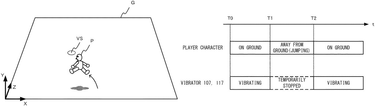
FIG. 11is a diagram showing an example of timings of a jumping motion of the player character P and vibrations of the vibrators107and117.
As shown inFIG. 11, when the player character P is in contact with the ground object G without performing a jumping motion, the vibrators107and117vibrate (from time T0to time T1). It should be noted that the vibration strengths (amplitudes) of the vibrators107and117vary according to the distance between the vibration object VS and the player character P. The vibration strengths of the vibrators107and117are increased with a decrease in the distance between the vibration object VS and the player character P. Further, even when the player character P is in contact with the ground object G, then if the player character P is away from the vibration object VS by at least a predetermined distance, none of the vibrators107and117vibrates.
Here, it is assumed that, at time T1, the player character P performs a jumping motion according to an operation performed by the player. When the player character P performs a jumping motion, the player character P is temporarily not in contact with the ground object G (from time T1to time T2). During this period of time from T1to T2, the vibrations of the vibrators107and117are stopped.
When, at time T2, the player character P comes into contact with the ground object G again, the vibrators107and117resume vibrating. After time T2, the player character P continues to be in contact with the ground object G, and therefore, the vibrators107and117continues to vibrate as long as the player character P is not away from the vibration object VS by at least the predetermined distance.
Thus, in the exemplary embodiment, when the player character P performs a jumping motion, so that the player character P is temporarily away from the ground object G, the vibrations of the left and right controllers3and4are temporarily stopped. As a result, the player can recognize that the ground object G (specifically, the vibration object VS buried under the ground object G) is vibrating.
It should be noted that a vibration caused by the vibration object VS (hereinafter referred to as a “first vibration”) and a vibration caused by an object other than the vibration object VS may occur simultaneously. For example, when the player character P is holding or carrying an item object that vibrates, or is traveling on or in a vehicle object that vibrates, a vibration caused by the item or vehicle object (hereinafter referred to as a “second vibration”) occurs. When the player character P is holding or carrying an item object that vibrates, or is traveling on or in a vehicle object that vibrates, then if the player character P or the vehicle object is in contact with the ground object G, the first and second vibrations occur simultenously.
When the first and second vibrations occur simultaneously, a combined vibration produced by combining the first and second vibrations is perceived by the player. In this case, when the player character P performs a jumping motion, the player character P is not in contact with the ground object G, and therefore, the first vibration is temporarily stopped. Meanwhile, even when the player character P performs a jumping motion, so that the player character P is not in contact with the ground object G, the item or vehicle object is in contact with the player character P, and therefore, the second vibration is continued. Thus, when the player character P is in contact with the ground object G, the player perceives a combined vibration produced by combining the first and second vibrations, and while the player character P is performing a jumping motion, the player perceives only the second vibration. When the player character P comes into contact with the ground object G again, the player will perceive the combined vibration.
It should be noted that a plurality of vibrations may be combined in accordance with the superposition principle of wave, for example. Further, a plurality of vibrations may be combined using other techniques. For example, in a case where the two vibration waveforms V1and V2are combined, the amplitude value of the combined waveform may be calculated by adding the amplitude values of the vibration waveforms V1and V2together at that moment. Further, the frequency of the combined waveform may be calculated by averaging the frequencies of the vibration waveforms V1and V2at that moment.
Further, a plurality of vibrations may be combined using one of a plurality of waveforms that has a greatest amplitude. For example, in a case where the two vibration waveforms V1and V2are combined, if the amplitude value of the vibration waveform V1is greater than the amplitude value of the vibration waveform V2at that moment, the combined waveform may be the vibration waveform V1. Further, when the amplitude value of the vibration waveform V2is greater than the amplitude value of the vibration waveform V1at another moment, the combined waveform may be the vibration waveform V2.
Next, the control of the vibrators107and117of the left and right controllers3and4will be specifically described.FIG. 12is a diagram for describing the control of the vibrations that is performed according to the positional relationship between the player character P and the vibration object VS.FIG. 12shows the virtual space as viewed from above.
The main body apparatus2previously stores vibration pattern data for the vibration object VS, and calculates a frequency and an amplitude, based on the vibration pattern data. By adjusting the amplitude based on the vibration pattern data, the vibration strengths of the vibrators107and117are calculated.
Specifically, as shown inFIG. 12, initially, a vector Ve pointing from the location of the player character P to the location of the vibration object VS is calculated, and the magnitude of the vector Ve (the distance between the player character P and the vibration object VS) is calculated. By adjusting the amplitude based on the vibration pattern data on the basis of the distance between the player character P and the vibration object VS, a “reference vibration strength (amplitude)” of the vibrators107and117is calculated.
For example, the “reference vibration strength” is determined by multiplying the amplitude based on the vibration pattern data by a coefficient corresponding to the distance between the player character P and the vibration object VS. The “reference vibration strength” is determined within the range of, for example, 0 to 1. The “reference vibration strength” increases with a decrease in the distance between the player character P and the vibration object VS. For example, the reference vibration strength may decrease in a manner represented by a linear function as the distance increases. Further, the reference vibration strength may be inversely proportional to the distance. Further, the reference vibration strength may be fixed in a case where the distance is within a predetermined range, and may decrease with an increase in the distance in a case where the distance is greater than or equal to a predetermined distance. The relationship between the distance and the reference vibration strength may be determined based on any other suitable functions.
After the “reference vibration strength” has been determined, the ratio of the vibration strengths of the vibrators107and117is determined. Specifically, in the virtual space, reference points L and R are set on a straight line that passes through the location of the player character P and extends parallel to the X-axis. An angle θL between a vector pointing from the location of the player character P toward the reference point L, and the vector Ve, is calculated. Based on the angle θL, a damping coefficient CL is calculated. The damping coefficient CL is calculated within the range of, for example, 0 to 1. For example, the damping coefficient CL is set to “1” in a case where the angle θL is within the range of 0° to 90°, and is set to be smaller than “1” in a case where the angle θL exceeds 90°. The damping coefficient CL may be set to “0” in a case where the angle θL is 180°. Further, for example, as the angle θL changes from 0° to 180°, the damping coefficient CL may linearly change from 1 to 0. By multiplying the “reference vibration strength” determined according to the distance between the player character P and the vibration object VS by the damping coefficient CL calculated based on the angle θL, the vibration strength (amplitude) of the vibrator107is determined.
The same applies to the vibrator117of the right controller4. The vibration strength of the vibrator117of the right controller4is determined based on an angle θR between a vector pointing from the location of the player character P toward the reference point R, and the vector Ve. Specifically, by calculating a damping coefficient CR (e.g., within the range of 0 to 1) based on the angle θR, and multiplying the “reference vibration strength” determined according to the distance between the player character P and the vibration object VS by the damping coefficient CR, the vibration strength (amplitude) of the vibrator117is determined.
For example, when the angle θL is equal to the angle θR (i.e., both are 90°), the vibrators107and117vibrate with the same strength. Further, when the angle θL is smaller than 90° and the angle θR is greater than 90°, the vibrator107vibrates more strongly than the vibrator117.
It should be noted that, in the above exemplary embodiment, it is assumed that the virtual camera is fixed in the virtual space, and alternatively, the location and orientation of the virtual camera may be changed according to an operation performed by the player, or may be automatically changed by a program. In this case, the angles θL and θR may be changed according to the orientation of the virtual camera. For example, in a case where a fixed camera coordinate system may be set for the virtual camera, and the Xc axis of the camera coordinate system is set as the rightward direction of the virtual camera, the reference points L and R may be set on a straight line that passes through the location of the player character P and extends parallel to the Xc axis. The angles θL and θR may be calculated based on the reference points L and R, and the vibration strengths of the vibrators107and117may be calculated.
A first vibration control signal containing the frequency and vibration strength (amplitude) of the vibrator107thus calculated is generated and output to the left controller3. Similarly, a second vibration control signal containing the frequency and vibration strength (amplitude) of the vibrator117thus calculated is generated and output to the right controller4.
When the player character P is in contact with the ground object G, the first and second vibration control signals are generated and output to the left and right controllers3and4, respectively, at predetermined time intervals (e.g., intervals of 5 msec). As a result, the vibrators107and117vibrate with a waveform corresponding to vibration pattern data, and with strengths corresponding to the positional relationship between the player character P and the vibration object VS. While the player character P is in contact with the ground object G, the playback of a vibration waveform based on vibration pattern data is repeatedly performed.
Meanwhile, when the player character P performs a jumping motion, so that the player character P is temporarily not in contact with the ground object G, the generation and output of the vibration control signals are temporarily stopped. Therefore, none of the vibrators107and117vibrates. Even in the middle of the playback of a vibration waveform based on the previously stored vibration pattern data, when the player character P leaves the ground object G, the generation and output of the vibration control signals are stopped. When the player character P comes into contact with the ground object G again, the generation and output of the vibration control signals are resumed. In this case, the vibration pattern data (file) may be played back from the beginning thereof, or from a partway point (a point where the playback is temporarily stopped).
As described above, in the exemplary embodiment, when the player character P performs a jumping motion, so that the ground object G is temporarily not in contact with the ground object G, the generation and output of the first and second vibration control signals are temporarily stopped. That is, a vibration that occurs due to contact with the ground object G (a vibration caused by the vibration object VS) is temporarily stopped. As a result, the left and right controllers3and4temporarily stop vibrating. Therefore, by causing the player character P to perform a jumping motion, the player can easily recognize that the ground object G is vibrating. Even when a vibration caused by the vibration object VS and another vibration are simultaneously occurring, then if the player character P performs a jumping motion, a vibration caused by the vibration object VS is temporarily stopped, and therefore, the player can feel a change in vibration. Therefore, by causing the player character P to perform a jumping motion, the player can easily recognize that the ground object G is vibrating. Further, based on the ratio of the vibration strengths of the left and right controllers3and4, the player can recognize where a vibration source is located in the virtual space.
(Details of Process)
Next, a process performed in the main body apparatus2of the game system1will be performed in detail. Firstly, data stored in the main body apparatus2will be described. Afterwards, a description of information processing performed in the main body apparatus2will be provided.FIG. 13is a diagram showing an example of data stored in the main body apparatus2.
As shown inFIG. 13, the main body apparatus2stores a game program D101, operation data D102, character data D103, vibration object data D104, ground object data D105, a left vibration control signal D106, and a right vibration control signal D107. It should be noted that the main body apparatus2stores various other data and programs in addition to those shown inFIG. 13.
The game program D101is for executing the above game.
The operation data D102corresponds to operations performed on the left and right controllers3and4, and is transmitted from the left and right controllers3and4. In the exemplary embodiment, the main body apparatus2communicates with the left and right controllers3and4at predetermined time intervals (e.g., intervals of 1/200 sec). In the communication, the left and right controllers3and4transmit the operation data D102to the main body apparatus2. Further, in the communication, the left and right vibration control signals D106and D107are transmitted from the main body apparatus2to the left and right controllers3and4, respectively.
The character data D103contains information related to the location, orientation, movement speed, movement direction, jump direction, jump speed, etc., of the player character P.
The vibration object data D104contains information related to the location of the vibration object VS in the virtual space. Further, the vibration object data D104contains vibration pattern data (data representing a vibration waveform) corresponding to the vibration object VS.
The ground object data D105is data (position data, polygon data, texture data, etc.) related to the ground object G provided in the virtual space.
The left vibration control signal D106is data indicating the first vibration control signal for causing the vibrator107of the left controller3to vibrate, and contains a frequency and an amplitude. The right vibration control signal D107is data indicating the second vibration control signal for causing the vibrator117of the right controller4to vibrate, and contains a frequency and an amplitude.
Next, a process performed in the main body apparatus2will be described in detail.
FIG. 14is a flowchart showing a detailed process that is performed in the main body apparatus2when the game according to the exemplary embodiment is executed. The process ofFIG. 14is performed by the processor81of the main body apparatus2executing the game program D101(information processing program).
As shown inFIG. 14, initially, the processor81of the main body apparatus2(hereinafter simply referred to as “the main body apparatus2”) configures initial settings (step S1). Specifically, the main body apparatus2sets the virtual space, and provides the ground object G, the vibration object VS, and the player character P in the virtual space. Further, the main body apparatus2sets the virtual camera in the virtual space at a predetermined location. After step S1, the main body apparatus2repeatedly executes steps S2to S12at intervals of, for example, 1/60 sec (called a one-frame time).
Following step S1, the main body apparatus2acquires operation data transmitted from the left and right controllers3and4(step S2). Specifically, the left and right controllers3and4transmit operation data corresponding to an operation to the main body apparatus2at predetermined time intervals (e.g., intervals of 1/200 sec). The main body apparatus2temporarily stores the operation data received from the left and right controllers3and4in the DRAM85. In step S2, the main body apparatus2acquires the operation data stored in the DRAM85.
Next, the main body apparatus2causes the player character P to perform a motion in the virtual space, based on the acquired operation data (step S3). For example, when the stick32of the left controller3is operated, the main body apparatus2causes the player character P to move in the virtual space in a direction corresponding to the operation direction of the stick32, and updates the location and orientation of the player character P. Further, for example, when an operation button (e.g., the A-button53) of the right controller4is pressed down, the main body apparatus2causes the player character P to jump in the virtual space, and updates the location and orientation of the player character P.
Specifically, virtual gravity exists in the virtual space, and the main body apparatus2updates the location of the player character P, based on the virtual gravity and a motion state of the player character P. When the player character P does not perform a jumping motion, the Y-coordinate value of the player character P is “0.” When the player character P performs a jumping motion, the main body apparatus2calculates the location (the X-coordinate value, the Y-coordinate value, the Z-coordinate value) of the player character P in the current frame, based on the jump speed, the jump direction, and the virtual gravity. It should be noted that the player character P may perform a plurality of types of jumping motions. The jump speed and the jump direction may vary according to the jumping motion type, and a time it takes for the player character P to leave the ground object G and drop on the ground object G again may vary. The main body apparatus2stores the updated location and orientation of the player character P as the character data D103.
Following step S3, the main body apparatus2calculates the distance between the vibration object VS and the player character P (step S4). Next, the main body apparatus2determines whether or not the distance calculated in step S4is shorter than or equal to a predetermined threshold (step S5).
If the main body apparatus2determines that the distance is shorter than or equal to the predetermined threshold (step S5: YES), the main body apparatus2determines whether or not the player character P is in contact with the ground object G (step S6). Specifically, the main body apparatus2determines whether or not a polygon of the ground object G collides with a polygon of the player character P, based on the locations of the player character P and the ground object G It should be noted that the main body apparatus2may determine whether or not the player character P is in contact with the ground object G, based on the location in the Y-axis direction of the player character P.
It should be noted that even when the player character P performs a jumping motion, then if there is an object that blocks the jumping motion, for example, above the head of the player character P, the player character P does not leave the ground object G. In this case, in step S6, the main body apparatus2determines that the player character P is in contact with the ground object G.
If the main body apparatus2determines that the player character P is in contact with the ground object G (step S6: YES), the main body apparatus2calculates the reference vibration strength, based on the distance calculated in step S4(step S7). Specifically, the main body apparatus2calculates a frequency F and an amplitude A, based on vibration pattern data corresponding to the vibration object VS. Thereafter, the main body apparatus2reduces the calculated amplitude A according to the distance calculated in step S4, to calculate a reference vibration strength A′.
Following step S7, the main body apparatus2calculates the angles θL and OR (step S8). Specifically, the main body apparatus2calculates the angle θL between a vector pointing in the negative direction of the X-axis of the virtual space and the vector Ve pointing from the player character P toward the vibration object VS. Further, the main body apparatus2calculates the angle θR between a vector pointing in the positive direction of the X-axis of the virtual space and the vector Ve pointing from the player character P toward the vibration object VS.
Next, the main body apparatus2calculates the vibration strengths of the left and right controllers3and4(step S9). Specifically, the main body apparatus2calculates the amplitude of the vibrator107of the left controller3, based on the reference vibration strength calculated in step S7and the angle θL calculated in step S8. Further, the main body apparatus2calculates the amplitude of the vibrator117of the right controller4, based on the reference vibration strength calculated in step S7and the angle θR calculated in step S8.
Next, the main body apparatus2generates vibration control signals that are to be output to the left and right controllers3and4(step S10). Specifically, the main body apparatus2generates a first vibration control signal containing the frequency F calculated in step S7and the amplitude of the vibrator107calculated in step S9, and stores the first vibration control signal as the left vibration control signal D106. Further, the main body apparatus2generates a second vibration control signal containing the frequency F calculated in step S7and the amplitude of the vibrator117calculated in step S9, and stores the second vibration control signal as the right vibration control signal D107. The left and right vibration control signals D106and D107are output from the main body apparatus2to the left and right controllers3and4, respectively, in communication between the main body apparatus2and the controllers (3and4).
If step S10has been performed, the determination result in step S5is negative (“NO”), or the determination result in step S6is negative (“NO”), the main body apparatus2generates an image of the virtual space using the virtual camera, and outputs the generated image to the display12(step S11).
Thus, if the main body apparatus2determines that the player character P is not in contact with the ground object G (step S6: NO), the main body apparatus2does not perform any of steps S7to S10. Therefore, while the player character P is not in contact with the ground object G, none of the first and second vibration control signals is generated, and none of the left and right controllers3and4vibrates.
Following step S11, the main body apparatus2determines whether or not to end the process ofFIG. 14(step S12). For example, if the location of the vibration object VS coincides with the location of the player character P, then when the player performs a specific operation, the main body apparatus2displays an image showing that the player character P has acquired a predetermined item, and ends the process ofFIG. 14. If, in step S12, the main body apparatus2determines not to end the process ofFIG. 14, the main body apparatus2executes step S2again. The description ofFIG. 14is ended.
It should be noted that the steps shown inFIG. 14are merely illustrative. For example, the steps may be executed in a different order, other steps may be added, or a portion of the steps may be removed. Further, the numerical values used in the steps are merely illustrative. Other values may be used.
As described above, in the exemplary embodiment, when an operation object (player character) that is operated by a player (user) is in contact with a predetermined surface (ground object) in a virtual space, a vibrator (the vibrators107and117) is caused to vibrate. When the operation object performs a motion of leaving the predetermined surface (jumping motion) according to an operation performed by the player, so that the operation object is away from the predetermined surface due to the motion, the vibrator is not caused to vibrate.
In the exemplary embodiment, it is assumed that the predetermined surface is always vibrating, and therefore, when the operation object is temporarily away from the predetermined surface, the vibration of the vibrator is stopped. Therefore, the player can easily recognize that the contact with the predetermined surface causes the vibration, and therefore, can easily identify the vibration source.
For example, when a controller vibrates, it may difficult for the player to identify the cause of the vibration of the controller. In particular, in a case where different vibrations are caused by different factors, it is difficult for the player to identify the cause of each vibration. For example, it is assumed that, in a game, a vibration occurs due to a predetermined operation performed by the player, and a plurality of objects are present in a virtual space, and a vibration occurs due to each object. In this case, it is difficult for the player to recognize whether a vibration has occurred due to the operation or any of the object. Further, when a vibration is occurring with a player character being moving on a relatively large surface, it is difficult for the player to recognize what causes the vibration of the controller because the vibration continues to occur.
In the exemplary embodiment, when a player character is in contact with a predetermined surface, a vibration occurs. When the player character is temporarily away from the predetermined surface, the vibration is temporarily stopped. Therefore, the player can easily recognize that the predetermined surface is vibrating.
Further, a vibration occurs due to an operation object being in contact with a predetermined surface. Therefore, the player feels as if the player itself were in contact with the predetermined surface in the virtual space, resulting in an increase in sense of realism in the game.
(Variations)
In the foregoing, the exemplary embodiment has been described. In other exemplary embodiments, the following features may be provided.
For example, in the above exemplary embodiment, it is assumed that the vibrations of the vibrators107and117are temporarily stopped by temporarily stopping the generation and output of the vibration control signals. In another exemplary embodiment, vibration control signals having an amplitude of “0” or substantially “0” may be generated and output to the left and right controllers3and4so that the vibrations of the vibrators107and117are temporarily stopped.
Further, in the above exemplary embodiment, a vibration occurs when an operation object is in contact with a predetermined surface. A vibration may occur not only when an operation object is perfectly in contact with a predetermined surface, but also when an operation object is in a slight floating state over a predetermined surface. In this case, when an operation object performs a motion of leaving a predetermined surface, a vibration is stopped. That is, when an operation object is in contact with a predetermined surface (the operation object is perfectly in contact with the predetermined surface, or the operation object is slightly floating), a vibration may occurs, and when an operation object performs a motion of leaving a predetermined surface, a vibration may not occur.
Further, in the above exemplary embodiment, it is assumed that a ground vibrates in a virtual space. In another exemplary embodiment, any other suitable object may vibrate. In this case, when a player character is in contact with a predetermined surface forming the object (a surface forming all or a portion of the object; the surface may be either a curved surface or a plane), the left and right controllers3and4are caused to vibrate. On the other hand, when the player character is not in contact with the predetermined surface forming the object, none of the left and right controllers3and4is caused to vibrate. For example, the above game may be performed, assuming that a wall object (or another object buried inside the wall object) vibrates. Further, when a player character is in or on a vehicle object, the vehicle object may be a vibration source. In this case, when the player character is in contact with a predetermined surface forming the vehicle object, the left and right controllers3and4may vibrate, and when the player character is temporarily away from the predetermined surface forming the vehicle object (e.g., the player character performs a jumping motion, so that the player character is temporarily away from the vehicle object), none of the left and right controllers3and4may vibrate.
Further, in the above exemplary embodiment, it is assumed that two controllers (3and4) are caused to vibrate. Alternatively, one or at least three controllers may be caused to vibrate.
Further, in the above exemplary embodiment, it is assumed that the left and right controllers3and4are attachable and detachable to and from the main body apparatus2. In another exemplary embodiment, the left and right controllers3and4may be integrated with the main body apparatus2so that the left and right controllers3and4are not detachable from the main body apparatus2.
Further, a single operation device in which the left and right controllers3and4are integrated together may be used. In this case, the operation device may have a left portion and a right portion. A vibrator may be provided in the left portion, and another vibrator may be provided in the right portion. The two vibrators may be caused to vibrate. Alternatively, a single vibrator may be provided in the operation device, and may be caused to vibrate.
Further, in the above exemplary embodiment, it is assumed that the processor81of the main body apparatus2functions as the character control section200, the image generation section201, and the vibration controller202. In another exemplary embodiment, at lesast one processor included in the game system1may function as the character control section200, the image generation section201, and the vibration controller202. For example, the left and right controllers3and4may function as the vibration controller202. For example, the left and right controllers3and4may generate the vibration control signals for causing the vibrators107and117to vibrate, in accordance with a command from the main body apparatus2, and output the vibration control signals to the vibrators107and117.
Further, the above game may be played in an information processing system in which a plurality of devices are connected together via a network (e.g., the Internet or a LAN). For example, a terminal and a server may be connected together via the Internet to constitute the above system. In this case, for example, the terminal may be provided with operation devices that are counterparts of the left and right controllers3and4, and a display device, and the server may be provided with the character control section200, the image generation section201, and the vibration signal generator202. The terminal transmits, to the server, operation data corresponding to an operation performed on the operation device by a player. The server controls a player character, etc., based on the operation data to generate an image, and generates a vibration control signal according to whether or not the player character is in contact with a predetermined surface, and transmits the image and the vibration control signal to the terminal. Thereafter, the terminal receives the image and the vibration control signal from the server, and displays the image on the display device, and causes the operation device to vibrate.
Further, the above game may be played in other systems (or devices), such as a personal computer, a smartphone, a tablet terminal, etc. Further, in the game system1or other systems, other applications may be executed in addition to the above game.
In the foregoing, the exemplary embodiment has been described. The above description of the exemplary embodiment is merely illustrative. Various modifications and changes may be made thereto.
While certain example systems, methods, devices and apparatuses have been described herein, it is to be understood that the appended claims are not to be limited to the systems, methods, devices and apparatuses disclosed, but on the contrary, are intended to cover various modifications and equivalent arrangements included within the spirit and scope of the appended claims.
Claims
- A non-transitory storage medium having stored therein a game program executable by a computer of an information processing apparatus, the program causing the computer to execute operations comprising: controlling an operation object in a virtual space, based on an operation performed by a player, and if the operation is performed with the operation object being in contact with a surface in the virtual space, causing the operation object to perform a motion of leaving the surface;controlling a first vibrator and a second vibrator such that the first and second vibrators perform a first vibration with respective vibration strengths that are based on a positional relationship in the virtual space between the operation object and a vibration object, when the operation object is in contact with the surface in the virtual space;and controlling the first and second vibrators to not perform the first vibration when the operation object is away from contact with the surface due to the motion.
- The non-transitory storage medium according to claim 1 , wherein controlling the first and second vibrators further includes controlling the first and second vibrators, based on a game process, such that the first and second vibrators performs a second vibration different from the first vibration, and when the first and second vibrators are controlled to perform the second vibration, controlling the first and second vibrators to perform the first and second vibrations when the operation object is in contact with the surface, and controlling the first and second vibrators to perform the second vibration without performing the first vibration when the operation object is away from the surface due to the motion.
- The non-transitory storage medium according to claim 1 , wherein the surface is a ground set in the virtual space.
- The non-transitory storage medium according to claim 1 , wherein the motion of leaving the surface is a jumping motion of the operation object.
- The non-transitory storage medium according to claim 1 , wherein controlling the vibrator includes controlling a vibration strength of each of the first and second vibrators according to the location of the operation object.
- The storage medium of claim 1 wherein the first vibrator is disposed in a left handheld and the second vibrator is disposed in a right handheld separate from the left handheld, the left and right handhelds being selectively attachable to and detachable from a housing providing a display that displays views of the virtual space including the operation object.
- An information processing apparatus comprising: an operation object controller configured to control an operation object in a virtual space, based on an operation performed by a player, and if the operation is performed with the operation object being in contact with a surface in the virtual space, causes the operation object to perform a motion of leaving the surface;and a vibration controller configured to control a first vibrator and a second vibrator such that the first and second vibrators performs a first vibration with respective vibration strengths that are based on a positional relationship in the virtual space between the operation object and a vibration object, when the operation object is in contact with the surface in the virtual space, and to control the first and second vibrators to not perform the first vibration when the operation object is away from contact with the surface due to the motion.
- The information processing apparatus according to claim 7 , wherein the vibration controller is further configured to control the first and second vibrators, based on a game process, such that the first and second vibrators performs a second vibration different from the first vibration, and when causing the first and second vibrators to perform the second vibration, the vibration controller controls the first and second vibrators such that the first and second vibrators performs the first and second vibrations when the operation object is in contact with the surface, and the first and second vibrators perform the second vibration without performing the first vibration when the operation object is away from the surface due to the motion.
- The information processing apparatus according to claim 7 , wherein the surface is a ground set in the virtual space.
- The information processing apparatus according to claim 7 , wherein the motion of leaving the surface is a jumping motion of the operation object.
- The information processing apparatus according to claim 7 , wherein the vibration controller controls a vibration strength of each of the first and second vibrators, based on a location of the operation object.
- The information processing apparatus of claim 7 wherein the first vibrator is disposed in a left handheld and the second vibrator is disposed in a right handheld separate from the left handheld, the left and right handhelds being selectively attachable to and detachable from a housing providing a display that displays views of the virtual space including the operation object.
- An information processing system comprising: a first vibrator and a second vibrator;an operation object controller configured to control an operation object in a virtual space, based on an operation performed by a player, and if the operation is performed with the operation object being in contact with a surface in the virtual space, causes the operation object to perform a motion of leaving the surface;and a vibration controller configured to control the first and second vibrators such that the first and second vibrators performs a first vibration with respective vibration strengths that are based on a positional relationship in the virtual space between the operation object and a vibration object, when the operation object is in contact with the surface in the virtual space, and to control the first and second vibrators to not perform the first vibration when the operation object is away from contact with the surface due to the motion.
- The information processing system according to claim 13 , wherein the vibration controller is further configured to control the first and second vibrators, based on a game process, such that the first and second vibrators perform a second vibration different from the first vibration, and when causing the first and second vibrators to perform the second vibration, the vibration controller controls the first and second vibrators such that the first and second vibrators perform the first and second vibrations when the operation object is in contact with the surface, and the first and second vibrators performs the second vibration without performing the first vibration when the operation object is away from the surface due to the motion.
- The information processing system according to claim 13 , wherein the surface is a ground set in the virtual space.
- The information processing system according to claim 13 , wherein the motion of leaving the surface is a jumping motion of the operation object.
- The information processing system according to claim 13 , wherein the vibration controller controls a vibration strength of each of the first and second vibrators according to a location of the operation object.
- The information processing system of claim 13 wherein the first vibrator is disposed in a left handheld and the second vibrator is disposed in a right handheld separate from the left handheld, the left and right handhelds being selectively attachable to and detachable from a housing providing a display that displays views of the virtual space including the operation object.
- An information processing method for use in an information processing system, the method comprising: controlling an operation object in a virtual space, based on an operation performed by a player, and if the operation is performed with the operation object being in contact with a surface in the virtual space, causing the operation object to perform a motion of leaving the surface;and controlling a first vibrator and a second vibrator such that the first and second vibrators performs a first vibration with respective strengths that are based on a positional relationship in the virtual space between the operation object and a vibration object, when the operation object is in contact with the surface in the virtual space, and such that the first and second vibrators do not perform the first vibration when the operation object is away from contact with the surface due to the motion.
- The information processing method according to claim 19 , wherein controlling the first and second vibrators further includes controlling the first and second vibrators, based on a game process, such that the first and second vibrators performs a second vibration different from the first vibration, and when the first and second vibrators are caused to perform the second vibration, the first and second vibrators are controlled to perform the first and second vibrations when the operation object is in contact with the surface, and the first and second vibrators are controlled to perform the second vibration without performing the first vibration when the operation object is away from the surface due to the motion.
- The information processing method according to claim 19 , wherein the surface is a ground set in the virtual space.
- The information processing method according to claim 19 , wherein the motion of leaving the surface is a jumping motion of the operation object.
- The information processing method according to claim 19 , wherein controlling the first and second vibrators includes controlling a vibration strength of each of the first and second vibrators according to a location of the operation object.
- The information processing system of claim 19 wherein the first vibrator is disposed in a left handheld and the second vibrator is disposed in a right handheld separate from the left handheld, the left and right handhelds being selectively attachable to and detachable from a housing providing a display that displays views of the virtual space including the operation object.
- The information processing system of claim 19 wherein the first vibrator is disposed in a left handheld and the second vibrator is disposed in a right handheld separate from the left handheld, the left and right handhelds being selectively attachable to and detachable from a housing providing a display that displays views of the virtual space including the operation object.
Disclaimer: Data collected from the USPTO and may be malformed, incomplete, and/or otherwise inaccurate.