U.S. Pat. No. 10,661,161
WIRELESS CHARGING ADAPTER WITH GAME CONTROL KEYS FOR COMPUTER GAME CONTROLLER
AssigneeSony Interactive Entertainment LLC
Issue DateAugust 24, 2018
Illustrative Figure
Abstract
A wireless charging adapter that can snap onto a computer game controller can be inductively coupled to a charging base to wirelessly recharge a battery in the controller. The adapter also can include keys that mirror keys on the controller so that a gamer can remove the adapter with controller from the charging base, keep the adapter on the controller, and use both the controller keys and adapter keys to control a computer game.
Description
DETAILED DESCRIPTION This disclosure relates generally to computer ecosystems including aspects of consumer electronics (CE) device networks such as but not limited to computer game networks. A system herein may include server and client components, connected over a network such that data may be exchanged between the client and server components. The client components may include one or more computing devices including game consoles such as Sony PlayStation® or a game console made by Microsoft or Nintendo or other manufacturer virtual reality (VR) headsets, augmented reality (AR) headsets, wireless battery rechargers, portable televisions (e.g. smart TVs, Internet-enabled TVs), portable computers such as laptops and tablet computers, and other mobile devices including smart phones and additional examples discussed below. These client devices may operate with a variety of operating environments. For example, some of the client computers may employ, as examples, Linux operating systems, operating systems from Microsoft, or a Unix operating system, or operating systems produced by Apple Computer or Google. These operating environments may be used to execute one or more browsing programs, such as a browser made by Microsoft or Google or Mozilla or other browser program that can access websites hosted by the Internet servers discussed below. Also, an operating environment according to present principles may be used to execute one or more computer game programs. Servers and/or gateways may include one or more processors executing instructions that configure the servers to receive and transmit data over a network such as the Internet. Or, a client and server can be connected over a local intranet or a virtual private network. A server or controller may be instantiated by a game console such as a Sony PlayStation®, a personal computer, etc. Information may be exchanged over a network between the clients and servers. To this end and for ...
DETAILED DESCRIPTION
This disclosure relates generally to computer ecosystems including aspects of consumer electronics (CE) device networks such as but not limited to computer game networks. A system herein may include server and client components, connected over a network such that data may be exchanged between the client and server components. The client components may include one or more computing devices including game consoles such as Sony PlayStation® or a game console made by Microsoft or Nintendo or other manufacturer virtual reality (VR) headsets, augmented reality (AR) headsets, wireless battery rechargers, portable televisions (e.g. smart TVs, Internet-enabled TVs), portable computers such as laptops and tablet computers, and other mobile devices including smart phones and additional examples discussed below. These client devices may operate with a variety of operating environments. For example, some of the client computers may employ, as examples, Linux operating systems, operating systems from Microsoft, or a Unix operating system, or operating systems produced by Apple Computer or Google. These operating environments may be used to execute one or more browsing programs, such as a browser made by Microsoft or Google or Mozilla or other browser program that can access websites hosted by the Internet servers discussed below. Also, an operating environment according to present principles may be used to execute one or more computer game programs.
Servers and/or gateways may include one or more processors executing instructions that configure the servers to receive and transmit data over a network such as the Internet. Or, a client and server can be connected over a local intranet or a virtual private network. A server or controller may be instantiated by a game console such as a Sony PlayStation®, a personal computer, etc.
Information may be exchanged over a network between the clients and servers. To this end and for security, servers and/or clients can include firewalls, load balancers, temporary storages, and proxies, and other network infrastructure for reliability and security. One or more servers may form an apparatus that implement methods of providing a secure community such as an online social website to network members.
As used herein, instructions refer to computer-implemented steps for processing information in the system. Instructions can be implemented in software, firmware or hardware and include any type of programmed step undertaken by components of the system.
A processor may be any conventional general-purpose single- or multi-chip processor that can execute logic by means of various lines such as address lines, data lines, and control lines and registers and shift registers.
Software modules described by way of the flow charts and user interfaces herein can include various sub-routines, procedures, etc. Without limiting the disclosure, logic stated to be executed by a particular module can be redistributed to other software modules and/or combined together in a single module and/or made available in a shareable library.
Present principles described herein can be implemented as hardware, software, firmware, or combinations thereof; hence, illustrative components, blocks, modules, circuits, and steps are set forth in terms of their functionality.
The functions and methods described below, when implemented in software, can be written in an appropriate language such as but not limited to Java, C # or C++, and can be stored on or transmitted through a computer-readable storage medium such as a random access memory (RAM), read-only memory (ROM), electrically erasable programmable read-only memory (EEPROM), compact disk read-only memory (CD-ROM) or other optical disk storage such as digital versatile disc (DVD), magnetic disk storage or other magnetic storage devices including removable thumb drives, etc. A connection may establish a computer-readable medium. Such connections can include, as examples, hard-wired cables including fiber optics and coaxial wires and digital subscriber line (DSL) and twisted pair wires. Such connections may include wireless communication connections including infrared and radio.
Components included in one embodiment can be used in other embodiments in any appropriate combination. For example, any of the various components described herein and/or depicted in the Figures may be combined, interchanged or excluded from other embodiments. “A system having at least one of A, B, and C” (likewise “a system having at least one of A, B, or C” and “a system having at least one of A, B, C”) includes systems that have A alone, B alone, C alone, A and B together, A and C together, B and C together, and/or A, B, and C together, etc.
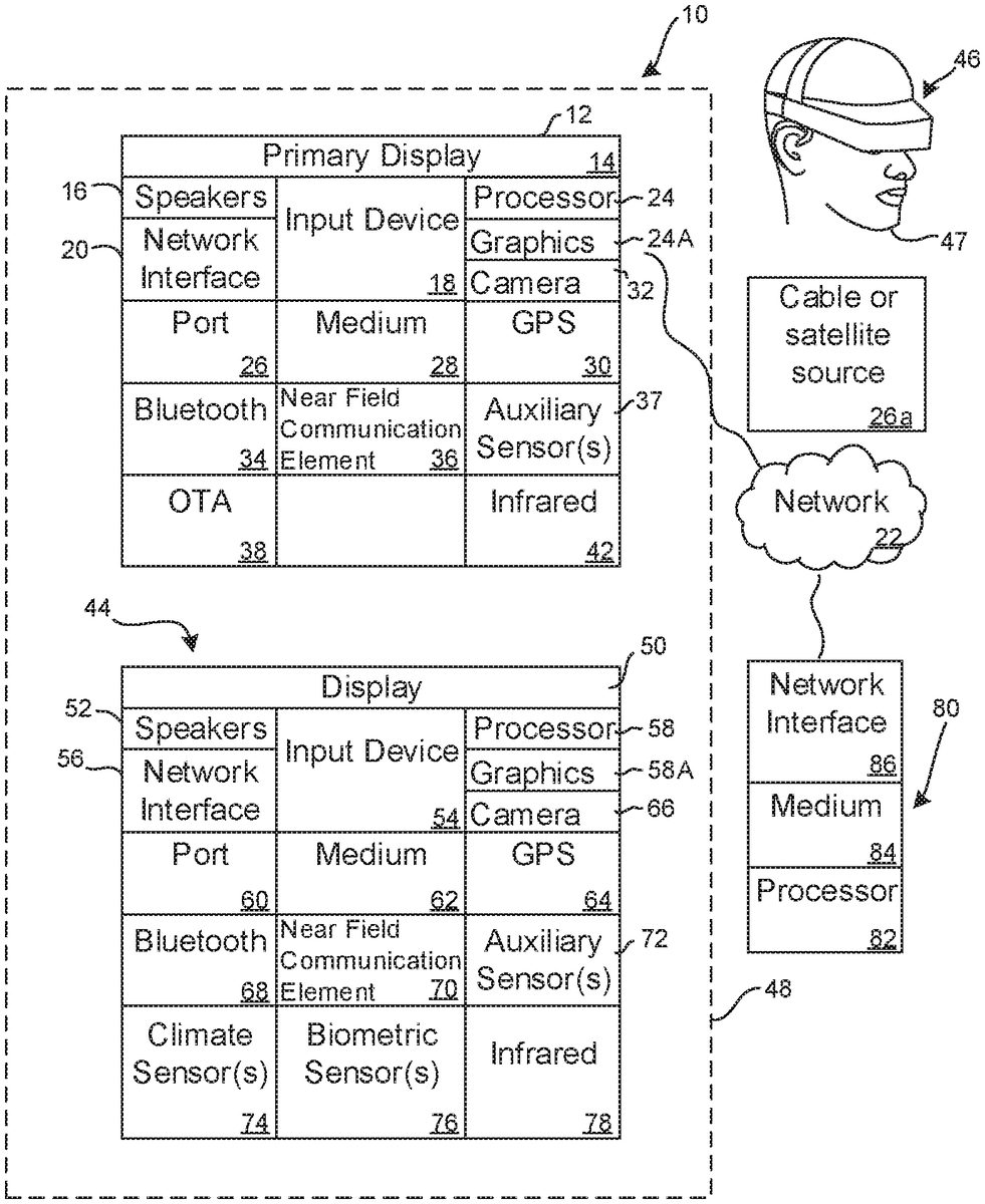
Now specifically referring toFIG. 1, an example system10is shown, which may include one or more of the example devices mentioned above and described further below in accordance with present principles. The first of the example devices included in the system10is a consumer electronics (CE) device such as an audio video device (AVD)12such as but not limited to an Internet-enabled TV with a TV tuner (equivalently, set top box controlling a TV). However, the AVD12alternatively may be an appliance or household item, e.g. computerized Internet enabled refrigerator, washer, or dryer. The AVD12alternatively may also be a computerized Internet enabled (“smart”) telephone, a tablet computer, a notebook computer, a wearable computerized device such as e.g. computerized Internet-enabled watch, a computerized Internet-enabled bracelet, other computerized Internet-enabled devices, a computerized Internet-enabled music player, computerized Internet-enabled head phones, a computerized Internet-enabled implantable device such as an implantable skin device, etc. Regardless, it is to be understood that the AVD12is configured to undertake present principles (e.g. communicate with other CE devices to undertake present principles, execute the logic described herein, and perform any other functions and/or operations described herein).
Accordingly, to undertake such principles the AVD12can be established by some or all of the components shown inFIG. 1. For example, the AVD12can include one or more displays14that may be implemented by a high definition or ultra-high definition “4K” or higher flat screen and that may be touch-enabled for receiving user input signals via touches on the display. The AVD12may include one or more speakers16for outputting audio in accordance with present principles, and at least one additional input device18such as e.g. an audio receiver/microphone for e.g. entering audible commands to the AVD12to control the AVD12. The example AVD12may also include one or more network interfaces20for communication over at least one network22such as the Internet, an WAN, an LAN, etc. under control of one or more processors24. A graphics processor24A may also be included. Thus, the interface20may be, without limitation, a Wi-Fi transceiver, which is an example of a wireless computer network interface, such as but not limited to a mesh network transceiver. It is to be understood that the processor24controls the AVD12to undertake present principles, including the other elements of the AVD12described herein such as e.g. controlling the display14to present images thereon and receiving input therefrom. Furthermore, note the network interface20may be, e.g., a wired or wireless modem or router, or other appropriate interface such as, e.g., a wireless telephony transceiver, or Wi-Fi transceiver as mentioned above, etc.
In addition to the foregoing, the AVD12may also include one or more input ports26such as, e.g., a high definition multimedia interface (HDMI) port or a USB port to physically connect (e.g. using a wired connection) to another CE device and/or a headphone port to connect headphones to the AVD12for presentation of audio from the AVD12to a user through the headphones. For example, the input port26may be connected via wire or wirelessly to a cable or satellite source26aof audio video content. Thus, the source26amay be, e.g., a separate or integrated set top box, or a satellite receiver. Or, the source26amay be a game console or disk player containing content such as computer game software and databases. The source26awhen implemented as a game console may include some or all of the components described below in relation to the CE device44.
The AVD12may further include one or more computer memories28such as disk-based or solid-state storage that are not transitory signals, in some cases embodied in the chassis of the AVD as standalone devices or as a personal video recording device (PVR) or video disk player either internal or external to the chassis of the AVD for playing back AV programs or as removable memory media. Also, in some embodiments, the AVD12can include a position or location receiver such as but not limited to a cellphone receiver, GPS receiver and/or altimeter30that is configured to e.g. receive geographic position information from at least one satellite or cellphone tower and provide the information to the processor24and/or determine an altitude at which the AVD12is disposed in conjunction with the processor24. However, it is to be understood that another suitable position receiver other than a cellphone receiver, GPS receiver and/or altimeter may be used in accordance with present principles to e.g. determine the location of the AVD12in e.g. all three dimensions.
Continuing the description of the AVD12, in some embodiments the AVD12may include one or more cameras32that may be, e.g., a thermal imaging camera, a digital camera such as a webcam, and/or a camera integrated into the AVD12and controllable by the processor24to gather pictures/images and/or video in accordance with present principles. Also included on the AVD12may be a Bluetooth transceiver34and other Near Field Communication (NFC) element36for communication with other devices using Bluetooth and/or NFC technology, respectively. An example NFC element can be a radio frequency identification (RFID) element. Zigbee also may be used.
Further still, the AVD12may include one or more auxiliary sensors37(e.g., a motion sensor such as an accelerometer, gyroscope, cyclometer, or a magnetic sensor, an infrared (IR) sensor, an optical sensor, a speed and/or cadence sensor, a gesture sensor (e.g. for sensing gesture command), etc.) providing input to the processor24. The AVD12may include an over-the-air TV broadcast port38for receiving OTA TV broadcasts providing input to the processor24. In addition to the foregoing, it is noted that the AVD12may also include an infrared (IR) transmitter and/or IR receiver and/or IR transceiver42such as an IR data association (IRDA) device. A battery (not shown) may be provided for powering the AVD12.
Still referring toFIG. 1, in addition to the AVD12, the system10may include one or more other CE device types. In one example, a first CE device44may be a computer game console used to send computer game audio and video to the AVD12via commands sent directly to the AVD12and/or through the below-described server while a second CE device46may include similar components as the first CE device44. In the example shown, the second CE device46may be configured as a VR headset worn by a player47as shown, or a hand-held game controller manipulated by the player47. In the example shown, only two CE devices44,46are shown, it being understood that fewer or greater devices may be used.
In the example shown, to illustrate present principles all three devices12,44,46are assumed to be members of an entertainment network in, e.g., a home, or at least to be present in proximity to each other in a location such as a house. However, present principles are not limited to a particular location, illustrated by dashed lines48, unless explicitly claimed otherwise.
The example non-limiting first CE device44may be established by any one of the above-mentioned devices, for example, a portable wireless laptop computer or notebook computer or game console, and accordingly may have one or more of the components described below. The first CE device44may be a remote control (RC) for, e.g., issuing AV play and pause commands to the AVD12, or it may be a more sophisticated device such as a tablet computer, a game controller communicating via wired or wireless link with the AVD12, a personal computer, a wireless telephone, etc.
Accordingly, the first CE device44may include one or more displays50that may be touch-enabled for receiving user input signals via touches on the display. The first CE device44may include one or more speakers52for outputting audio in accordance with present principles, and at least one additional input device54such as e.g. an audio receiver/microphone for e.g. entering audible commands to the first CE device44to control the device44. The example first CE device44may also include one or more network interfaces56for communication over the network22under control of one or more CE device processors58. A graphics processor58A may also be included. Thus, the interface56may be, without limitation, a Wi-Fi transceiver, which is an example of a wireless computer network interface, including mesh network interfaces. It is to be understood that the processor58controls the first CE device44to undertake present principles, including the other elements of the first CE device44described herein such as e.g. controlling the display50to present images thereon and receiving input therefrom. Furthermore, note the network interface56may be, e.g., a wired or wireless modem or router, or other appropriate interface such as, e.g., a wireless telephony transceiver, or Wi-Fi transceiver as mentioned above, etc.
In addition to the foregoing, the first CE device44may also include one or more input ports60such as, e.g., a HDMI port or a USB port to physically connect (e.g. using a wired connection) to another CE device and/or a headphone port to connect headphones to the first CE device44for presentation of audio from the first CE device44to a user through the headphones. The first CE device44may further include one or more tangible computer readable storage medium62such as disk-based or solid-state storage. Also in some embodiments, the first CE device44can include a position or location receiver such as but not limited to a cellphone and/or GPS receiver and/or altimeter64that is configured to e.g. receive geographic position information from at least one satellite and/or cell tower, using triangulation, and provide the information to the CE device processor58and/or determine an altitude at which the first CE device44is disposed in conjunction with the CE device processor58. However, it is to be understood that another suitable position receiver other than a cellphone and/or GPS receiver and/or altimeter may be used in accordance with present principles to e.g. determine the location of the first CE device44in e.g. all three dimensions.
Continuing the description of the first CE device44, in some embodiments the first CE device44may include one or more cameras66that may be, e.g., a thermal imaging camera, a digital camera such as a webcam, and/or a camera integrated into the first CE device44and controllable by the CE device processor58to gather pictures/images and/or video in accordance with present principles. Also included on the first CE device44may be a Bluetooth transceiver68and other Near Field Communication (NFC) element70for communication with other devices using Bluetooth and/or NFC technology, respectively. An example NFC element can be a radio frequency identification (RFID) element.
Further still, the first CE device44may include one or more auxiliary sensors72(e.g., a motion sensor such as an accelerometer, gyroscope, cyclometer, or a magnetic sensor, an infrared (IR) sensor, an optical sensor, a speed and/or cadence sensor, a gesture sensor (e.g. for sensing gesture command), etc.) providing input to the CE device processor58. The first CE device44may include still other sensors such as e.g. one or more climate sensors74(e.g. barometers, humidity sensors, wind sensors, light sensors, temperature sensors, etc.) and/or one or more biometric sensors76providing input to the CE device processor58. In addition to the foregoing, it is noted that in some embodiments the first CE device44may also include an infrared (IR) transmitter and/or IR receiver and/or IR transceiver78such as an IR data association (IRDA) device. A battery (not shown) may be provided for powering the first CE device44. The CE device44may communicate with the AVD12through any of the above-described communication modes and related components.
The second CE device46may include some or all of the components shown for the CE device44. Either one or both CE devices may be powered by one or more batteries.
Now in reference to the afore-mentioned at least one server80, it includes at least one server processor82, at least one tangible computer readable storage medium84such as disk-based or solid state storage, and at least one network interface86that, under control of the server processor82, allows for communication with the other devices ofFIG. 1over the network22, and indeed may facilitate communication between servers and client devices in accordance with present principles. Note that the network interface86may be, e.g., a wired or wireless modem or router, Wi-Fi transceiver, or other appropriate interface such as, e.g., a wireless telephony transceiver.
Accordingly, in some embodiments the server80may be an Internet server or an entire server “farm” and may include and perform “cloud” functions such that the devices of the system10may access a “cloud” environment via the server80in example embodiments for, e.g., network gaming applications. Or, the server80may be implemented by one or more game consoles or other computers in the same room as the other devices shown inFIG. 1or nearby.
Further to what has been alluded to above, logical blocks, modules, and circuits described below can be implemented or performed with a general purpose processor, a digital signal processor (DSP), a field programmable gate array (FPGA) or other programmable logic device such as an application specific integrated circuit (ASIC), discrete gate or transistor logic, discrete hardware components, or any combination thereof designed to perform the functions described herein. A processor can be implemented by a controller or state machine or a combination of computing devices. Thus, the methods herein may be implemented as software instructions executed by a processor, suitably configured application specific integrated circuits (ASIC) or field programmable gate array (FPGA) modules, or any other convenient manner as would be appreciated by those skilled in those art. Where employed, the software instructions may be embodied in a non-transitory device such as a hard disk drive, CD ROM or Flash drive. The software code instructions may also be downloaded over the Internet.
FIG. 2illustrates an example assembly according to present principles. A computer game controller200such as a PlayStation® Dual Shock 4 controller or other controller, including XBox® controllers, includes a hand-holdable controller housing202that contains one or more batteries204and plural control keys206that are manipulable to input commands via wired and/or wireless paths to a computer game console208, such as a Sony PlayStation® console or Microsoft XBox® game console. The game console208presents computerized video games on a display210such as any suitable display described herein.
A wireless charging adapter (WCA)212is mechanically engageable with the game controller housing202and is electrically engageable with an electrical component in the controller housing202such as a signal transceiver assembly214(which may include a microprocessor) for purposes to be shortly disclosed. The WCA is also electrically connected to the battery204to charge the battery204. In an example, charging current and signals from manipulating the keys on the WCA212may be sent through a wired or wireless link216to a universal serial bus (USB) port218of the game controller200.
As shown, the WCA212includes one or more WCA keys220manipulable to input a command to the computer game console208. The WCA keys220have corresponding functions to respective keys206on the game controller housing202and may have the same shape and size as the respective keys206.
The example WCA212inFIG. 2may also include a processor222accessing instructions on a memory224for executing logic embodied as code according to present principles. The WCA212may also include one or more communication transceivers226such as Wi-Fi or Bluetooth or other communication interfaces. Also, the WCA212includes circuitry228for charging the battery204in the game controller200. The circuitry228may include a Qi coil and associated circuitry or it may include wireless recharging circuitry using standards other than Qi. The circuitry228may include conversion circuitry to convert AC power received from inductive coupling with the charging base described below to DC power to provide to the battery.
A charging base230is provided on which the WCA212while mechanically engaged with/to the game controller housing202can be placed to inductively couple the WCA with the charging base to supply charging power, e.g., from a wall socket “S” as shown, through the WCA to the battery204over a wireless charging path to recharge the battery. To this end, the base230may include a processor232and computer storage234for executing logic embodied as code according to present principles. The base230also includes inductive charging circuitry236that couples with the circuitry228in the WCA212to convey charge current to the battery204of the game controller200.
In cross-reference toFIGS. 2 and 3, the charging base230includes a flat mat-like surface238on which the WCA212is positioned to charge the battery204of the game controller200. The charging base can be configured to hold plural game controllers with respective adapters as shown at one time for charging the plural game controllers simultaneously, and to this end outlines240of the game controllers may be printed or otherwise formed on the surface238to aid in proper placement of the controller/adapter assembly on the base.
FIG. 4shows that the controller housing202includes a front portion400holding the plural controller keys206and a rear portion402facing away from the front portion400. The WCA212with WCA keys220is mechanically engageable with the rear portion402of the controller housing202. The WCA212may be formed with structure to engage corresponding structure on the game controller housing202in an interference fit, or a snapping fit, so that the WCA212may be engaged and disengaged with the controller housing202by hand without the need for connectors such as threaded fasteners. In other embodiments, fasteners may be used.
FIGS. 5 and 6illustrate an example embodiment of a WCA212. As shown best inFIG. 5, the example WCA may be a unitarily-formed lightweight plastic or metal structure with a generally parallelepiped-shaped body500bounded on its rear side502by left and right flanges504that are thinner than the body500as shown. Respective left and right grip legs506may extend rearwardly away from the body (relative to the rear side502) from each flange504, with the flanges504/legs506forming “L”-shaped engagement members as shown.
The WCA212may be mounted onto the game controller body202as shown inFIG. 6by pushing the WCA212onto the body202such that the “L”-shaped engagement members of the WCA212engage respective structure on the body202in an interference fit.
In the discussions herein, it is to be understood that the divulged functionalities including illuminating lamps, transferring game commands from WCA key212manipulations, etc. may be effected by one or more processors in the WCA, one or more processors in the game controller that receive information from the WCA, one or more processors in the game console that communicate with the game controller and/or WCA, or any combination of the above.
FIG. 7illustrates additional features that may be provided on a WCA according to present principles in example implementations.FIG. 7illustrates one or more of the WCA keys220discussed above in reference toFIG. 2, showing one key on each respective flange504, it being understood that other key locations on the WCA may be used. In general, each WCA key220, when manipulated, causes a signal to be generated to command a function through the controller to the game console that is a copy the functionality of the commands when one or more dedicated keys of the game controller are manipulated. Thus, the same command functionality may be input by manipulating wither a WCA key or the game controller key copied by the WCA key. Preferably, the WCA keys220are strategically located on the WCA for accessibility by one or more fingers of the user when, for example, the user holds the game controller naturally in the orientation intended with his or her fingers at rest, hovering over the WCA keys220. Note that one or more of the WCA keys220may be simple toggle-like buttons or may be pressed bi-directionally, i.e., pulled like a trigger and pushed towards the front/outside of the WCA to establish two separate commands, one for each action.
As also shown inFIG. 7, the WCA212may support one or more lamps700. In an example, the lamps700may be light emitting diodes (LEDs) each with multiple illuminating elements to emit respective different colors, e.g., red and green. The lamps700may be used for multiple purposes. For example, the lamps700can be selectively illuminated to indicate which WCA keys220are mapped to which controller keys206. For example, a set pattern of illumination or sequence of lamp flashing can be used in an intuitive and informative manner to the user to know what controller keys are mapped to the WCA keys. As but one example, the lamps700may be illuminated left to right to indicate that the function of the right-most controller key206is mapped to a WCA key220, such as the right-most WCA key. Or, the lamps700may be arranged on the WCA212in the same pattern as the controller keys206are arranged on the controller, with the lamps in corresponding locations of controller keys whose functions are mapped to WCA keys being illuminated and the remaining lamps remaining off.
The lamps700may also be selectively illuminated to indicate that the adapter/controller is in charging mode. For example, one or more green lamps may be flashed on and off to indicate charging. The lamps may also be selectively illuminated to indicate a level of charge of the battery in the game controller. For example, one green lamp illuminated may indicate a relatively low level of charge while two green lamps illuminated may indicate a higher amount of charge remaining, and so on. Selective lamp illumination may also indicate both conditions of the controller with WCA being on the charging mat and charging and also being distanced from the mat and not charging but the controller is turned on and in use. Still further, the lamps700may be selectively illuminated to indicate that the adapter/controller not placed correctly on the charging mat to charge correctly or efficiently, e.g., by causing one or more red lamps700to flash.
In some implementations, the functions of the WCA keys220are established by the manufacturer to have default functions, e.g., the functions of predetermined keys “A” and “B” of the game controller200. If desired, the functional mapping of the WCA keys220can be changed to the functionality of any game controller key206as desired by the user. To this end, a settings key702may be provided on the WCA212as shown inFIG. 7, with attention now turned toFIG. 8.
At block800, as mentioned above the functions of the WCA keys220are established by, e.g., the manufacturer to have default functions corresponding to the functions of respective keys on the game controller200. Moving to block802, a setup command may be received. In one implementation, a setup command may be generated by a certain sequence of WCA key presses, if desired in combination with manipulation of the settings key702shown inFIG. 7. Correlation commands may be received at block804to correlate WCA key functions with game controller key functions. These commands may be established by simultaneously pressing a WCA key and the key on the game controller whose function is desired to be mapped to the manipulated WCA key. Based on these correlation commands, at block806the WCA keys are accorded the functions of the game controller keys to which they have been mapped.
FIG. 9illustrates that once WCA key functions have acquired the desired game controller key functions, at block900a WCA key manipulation may be received during game play. This causes a signal representing the function of the manipulated WCA key to be input to the game console, typically through the game controller, at block902. Manipulation of the corresponding game controller key also causes the same command function to be input to the game console.
FIGS. 10 and 11show alternate techniques for mapping game controller key functionality to the WCA keys220. InFIG. 10, a WCA1000that is in all essential respects identical to those described previously is shown, with the following exceptions. The WCA1000inFIG. 10may include a touch sensitive display1002with “soft” keys1004presented on the display1002in an arrangement that is the same arrangement1006as that of the game controller keys on the game controller. Indeed, an outline of the game controller may be provided as shown. The WCA keys1004have the same functions as the corresponding game controller keys have that are in the corresponding locations of the key arrangement on the game controller.
InFIG. 11, the display210shown inFIG. 2is caused by the game console to present an image1100of the game controller with modeled game controller keys1102. The modeled game controller keys1102can, for example, be caused to flash (as indicated at1104) one at a time for a short period each, with a prompt1106being presented to indicate that a press of a WCD key will result in the pressed key being given the function of the game controller key that corresponds to the flashing modeled game controller key1104. A user thus may view the display210and wait until a desired game controller key flashes, then press the WCA key that the user wishes to be accorded the function of the game controller key corresponding to the flashing image on the display210.
FIGS. 12 and 13illustrate an implementation of an adapter1200which omits the battery charging feature, and which is formed with a bay1202on a front side to receive a game controller. It is to be appreciated that the bay1202may be configured complementarily to the back surface of the game controller.
The bottom or rear1204surface of the adapter1200is opposite the bay1202as shown, any may include a set key1206and left and right command keys1208,1210. Indicators1212such as light emitted diodes (LEDs) may be visible on the bottom or rear surface1204as shown, and next to each indicator a respective icon1214may be printed or molded or etched or otherwise formed. The icons1214can represent respective keys on the game controller and can be presented with the same shape and features of the game controller keys.
To map a game controller key to one of the left or right adapter keys1208,1210, a user can press the set key1206and then press the left or right key1208,1210sought to be mapped. The first press of the key sought to be mapped may illuminate a first one of the indicators1212. The user can look at the illuminated indicator and corresponding icon and if the user wishes to map the corresponding game controller key to the adapter key sought to be mapped, release both the set key and the adapter key sought to be mapped. If the user wishes to map a different controller key to the adapter key sought to be mapped, he presses the adapter key sought to be mapped again, which causes another indicator1212to be illuminated for mapping the controller key represented by the icon1214associated with the indicator to the adapter key sought to be mapped according to principles above. The user can scroll through the indicators (and hence game controller keys) in this fashion by holding down the set key1206and toggling the adapter key sought to be mapped until the indicator representing the sought-after game controller key is illuminated, at which time the user releases the adapter keys to establish the mapping.
In other implementations, instead of a toggle-like set key1206, a multi-position toggle may be implemented and positioned to one of multiple settings, with each setting corresponding to a respective game controller key, to map the respective game controller key to whichever of the left and right adapter keys1208,1210is being pressed.
Returning toFIG. 12, an electrical connector1216, which may be removably engaged with the adapter1200, may extend away from the adapter1200into the bay1202to mechanically and electrically engage a complementarily-configured fitting on the game controller to mechanical stability plus an electrical connection pass-through, e.g., for a headphone connection. The connector1216is electrically connected to an electrical port1218that may receive, e.g., a headphone jack to establish electrical connection between the headphone jack and the game controller through the electrical connector1216.
It will be appreciated that whilst present principals have been described with reference to some example embodiments, these are not intended to be limiting, and that various alternative arrangements may be used to implement the subject matter claimed herein.
Claims
- An assembly, comprising: at least one game controller, the game controller comprising a hand-holdable controller housing comprising at least one battery and plural control keys manipulable to input commands including at least a first key manipulable to input a first command to a computer game console;at least one adapter mechanically engageable with the game controller and electrically engageable with at least one electrical component in the controller housing, the adapter comprising at least one adapter key manipulable to input the first command to the computer game console.
- The assembly of claim 1 , comprising at least one charging base on which the adapter mechanically engaged with/to the game controller can be placed to inductively couple the adapter with the charging base to supply charging power through the adapter to the battery over at least one wireless charging path to recharge the battery, wherein the charging base comprises a flat mat-like surface on which the adapter is positioned to charge the battery.
- The assembly of claim 1 , wherein the adapter is electrically engageable with the at least one electrical component in the controller housing through at least one electrical wire engaged with an input/output port on the game controller.
- The assembly of claim 1 , wherein the controller housing comprises a front portion holding the plural keys and a rear portion facing away from the front portion, and the adapter is mechanically engageable with the rear portion of the controller housing.
- The assembly of claim 1 , wherein the adapter is snappingly engageable and disengageable with the controller housing by hand without tools and without requiring connectors to hold the adapter on the controller housing.
- The assembly of claim 1 , wherein the adapter comprises one or more lamps to indicate a state of a battery in the game controller.
- The assembly of claim 2 , wherein the charging base is configured to hold plural game controllers at one time for charging the plural game controllers simultaneously.
- The assembly of claim 1 , wherein the controller includes at least a second key manipulable to input a second command to a computer game console, the adapter key is a first key, and the adapter comprises: at least a second key manipulable to input the second command to the computer game console.
- The assembly of claim 1 , wherein the adapter comprises one or more lamps to indicate a functional mapping of game controller keys to adapter keys.
- The assembly of claim 2 , wherein the adapter comprises conversion circuitry to convert AC power received from inductive coupling with the base to DC power to provide to the battery.
- A system comprising: at least one wireless charging adapter (WCA) comprising: a body that can snap onto a computer game controller comprising controller keys;an inductive circuit configured to be inductively coupled to a charging base to wirelessly recharge a battery in the computer game controller;and one or more keys that mirror respective controller keys on the computer game controller so that a gamer can remove the WCA with computer game controller from the charging base, keep the WCA on the computer game controller, and use both the controller keys and one or more adapter keys to control a computer game.
- The system of claim 11 , comprising the computer game controller.
- The system of claim 11 , comprising the charging base.
- The system of claim 11 , comprising a computer game console configured for executing commands generated by manipulating the controller keys and one or more adapter keys.
- The system of claim 11 , wherein the WCA is electrically engageable with at least one electrical component in the computer game controller through at least one electrical wire engaged with a universal serial bus (USB) port on the computer game controller.
- A method, comprising: mechanically coupling a wireless charging adapter (WCA) with a computer game controller;operating the WCA to send commands to a computer game console;operating the computer game controller to send commands to the computer game console;and placing the WCA on a charging base to recharge a battery in the computer game console.
- The method of claim 16 , comprising inductively coupling the WCA to the charging base to provide a wireless recharge path from the charging base to the computer game controller.
- The method of claim 16 , comprising electrically connecting the WCA to the computer game controller.
- The method of claim 18 , comprising electrically connecting the WCA to the computer game controller through at least one universal serial bus (USB) port on the computer game controller.
- The method of claim 16 , wherein the computer game controller comprises a front portion holding plural keys and a rear portion facing away from the front portion, and the method comprises: snapping the WCA onto the rear portion.
- The method of claim 16 , wherein the computer game controller comprises a front portion holding plural keys and a rear portion facing away from the front portion, and the method comprises: snapping the WCA onto the rear portion.
Disclaimer: Data collected from the USPTO and may be malformed, incomplete, and/or otherwise inaccurate.