U.S. Pat. No. 10,653,964
Transmitting Sensor Data Created in a Game Environment to a Set of Processors Outside the Game Environment Based on Predefined Event Determinations
AssigneeMurdock Wilbert Q; Williams Philip A
Issue DateMarch 22, 2017
Illustrative Figure
Abstract
The invention relates to a system that connects a game implement to a computer. Two or more persons are allowed to be interconnected and play interactively through the system.
Description
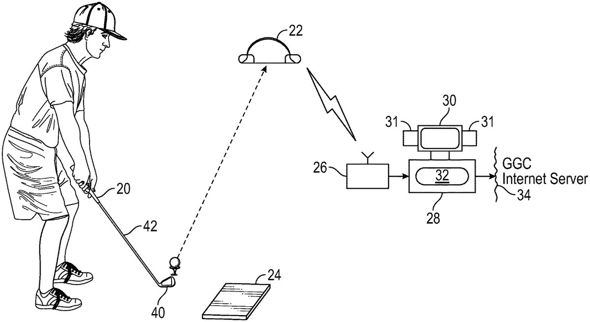
DETAILED DESCRIPTION OF THE DRAWINGS As shown inFIG. 1, a preferred embodiment of the invention includes a wireless smart golf club20, a wireless golf ball receptacle22, a wireless golf club motion sensing plate24, a wireless receiver26connected to a computer28, and a display or monitor30with speakers31operated under the control of golf system software32, and connected via the Internet to an Internet golf game server34(called herein the GGC server) The smart golf club20has a head40and a shaft42. As shown inFIGS. 2 and 3, the head40has a shaft opening42, a plurality of embedded contact sensors46(three are illustrated in the preferred embodiment), and the internal electronics circuitry48including a wireless radio frequency transmitter (58inFIG. 5). As shown, at least one of the sensors46is located at or proximate to the optimal location on a club face47for contact with the golf ball, the “sweet spot”49. The remaining two sensors are adjacent and on either side of the sweet spot49. The contact sensors may be, but are not limited to sensors employing piezoactive type transducers, specifically, either piezo-electric or piezo-resistive transducers (similar, but is not limited to the Cooper Instruments LPM 562). In an alternative embodiment,FIG. 3A, three sensors46are applied to the face of an adapted club by a Mylar tape or other means49. Again, the electronic circuitry is internal to the club-head40and connects to the sensors46by leads27. In a second alternative embodiment, to retrofit a standard golf club, contact sensors46are part of an adapter40attached to an ordinary club head as seen inFIG. 4, and wire connected to an electronic circuitry48attached to the club shaft42or elsewhere on the club. A golf ball contacting any sensor46produces a detectable variance indicating the magnitude and duration of sensor-ball impact. The variance may be a change in resistance of a piezo-resistive transducer or a voltage change in the case of a piezo-electric ...
DETAILED DESCRIPTION OF THE DRAWINGS
As shown inFIG. 1, a preferred embodiment of the invention includes a wireless smart golf club20, a wireless golf ball receptacle22, a wireless golf club motion sensing plate24, a wireless receiver26connected to a computer28, and a display or monitor30with speakers31operated under the control of golf system software32, and connected via the Internet to an Internet golf game server34(called herein the GGC server)
The smart golf club20has a head40and a shaft42. As shown inFIGS. 2 and 3, the head40has a shaft opening42, a plurality of embedded contact sensors46(three are illustrated in the preferred embodiment), and the internal electronics circuitry48including a wireless radio frequency transmitter (58inFIG. 5). As shown, at least one of the sensors46is located at or proximate to the optimal location on a club face47for contact with the golf ball, the “sweet spot”49. The remaining two sensors are adjacent and on either side of the sweet spot49. The contact sensors may be, but are not limited to sensors employing piezoactive type transducers, specifically, either piezo-electric or piezo-resistive transducers (similar, but is not limited to the Cooper Instruments LPM 562).
In an alternative embodiment,FIG. 3A, three sensors46are applied to the face of an adapted club by a Mylar tape or other means49. Again, the electronic circuitry is internal to the club-head40and connects to the sensors46by leads27.
In a second alternative embodiment, to retrofit a standard golf club, contact sensors46are part of an adapter40attached to an ordinary club head as seen inFIG. 4, and wire connected to an electronic circuitry48attached to the club shaft42or elsewhere on the club.
A golf ball contacting any sensor46produces a detectable variance indicating the magnitude and duration of sensor-ball impact. The variance may be a change in resistance of a piezo-resistive transducer or a voltage change in the case of a piezo-electric transducer. As shown inFIG. 5, the variance is detected and amplified by an associated amplifier52and is the input to an associated integration circuit54, the output of which represents the energy and impulse of the ball-club contact event. Connected to the integration circuit54, a microcontroller56is a multi-input signal processing circuit (similar, but not limited to a NXP MC9S08) having analog to digital signal converting circuits (ADCs), one for each input channel, and a sequential digital signal encoding circuit connected so as to convert the ADC outputs into a time multiplexed serial digital data stream containing a binary-coded word for each channel indicating the energy of the associated sensor-ball impact event.
The radio frequency transmitting circuit58receives the serial digital data from the microcontroller56and wirelessly transmits the information via an internal antenna60to a receiver26(FIG. 1) for subsequent processing by the computer28.
The golf ball receptacle22has a top62shaped to allow entry of a golf ball, as shown inFIGS. 6A, 6B, and 6C. The receptacle has a contact sensor pad64, shown inFIG. 7, containing at least one contact sensor (three different activation areas65,66, and67are illustrated in the preferred embodiment), a ball return mechanism69(FIG. 6B) and internal electronic circuitry68(FIG. 68). The internal circuitry includes a wireless radio frequency transmitter (not separately shown inFIGS. 6A, B and C). As shown, the preferred embodiment has contact sensor pad64positioned within the receptacle60such that the center activation area66aligns with the center of a ball entry70. Additional sensor activation area65and67are adjacent, one on either side of the center area66. In the preferred embodiment, ofFIGS. 6A, 6B, and 6C, and like the sensor used at the face of the club, the sensors may be, but are not limited to, sensors employing piezo-active type transducers, specifically, either piezo-electric or piezo-transducers.
A golf ball entering the receptacle60and containing the sensor pad65,66or67produces a detectable variance indicating the ball entry event. The variance may be a change in resistance in the case of a piezo-resistive transducer (similar, but not limited to Cooper instruments LPM 562) or a voltage change in the case of a piezo-electric transducer. As illustrated inFIG. 8, the variance is detected and amplified by an associated amplifier71. The amplified signal then is input to a microcontroller72having an analog to digital signal converting circuit (ADC) and a digital signal encoding circuit connected so as to convert the ADC output representing the sensors signals into a serial digital data stream containing a binary coded word indicating the sensor-ball contact event. The microcontroller72may be the same or similar to the microcontroller56of the golf club electronics. A radio frequency transmitter circuit74receives the serial digital data from the microcontroller72and wirelessly transmits the information via an internal antenna76to the receiver26(FIG. 1) for subsequent processing by the computer28.
The ball return mechanism68can be simple as a back plate80located to be engaged by a golf ball entering the receptacle22and supported and biased by a spring or springs82to eject the ball. Other known ejection devices, similar to those used in pinball machines and either mechanically, or even electrically activated, can be used to improve the effect if desired.
The receptacle configuration is susceptible to much variation. The receptacle illustrated and described above is well suited to indoor use, on carpet for example. It is clear, however, that an actual cup, installed in an actual green, with real or synthetic grass, can be similarly equipped.
The golf club motion sensor plate80having a top motion plate82and a bottom motion plate84is diagrammatically shown inFIGS. 9A-D, wherein the top motion plate82contains a plurality of capacitor-forming electrically isolated platelets83(twelve platelets are illustrated in this exemplary preferred embodiment). They are evenly distributed at or just below the top plate's exterior upper surface82. The bottom plate84has a homogenous electrically conductive interior surface85underlying the platelets83. Each capacitive platelet83contained in the top motion plate82forms a capacitive component when the top and bottom motion plates are vertically closely spaced to form the golf club motion sensor plate. A suitable dielectric may be sandwiched between the two plates. The structure is adhesively or otherwise mechanically joined and it may be covered or coated as desired. The result is a golf club motion sensor plate80containing a capacitor matrix (a 3×4 capacitor matrix is illustrated in the preferred embodiment). The capacitive components83are connected to form a capacitive network88as5indicated inFIG. 9E.
Applying an energizing high frequency alternating electrical signal having a frequency in 1e8 range from 100 MHz to 200 MHz from an oscillator87to the golf club motion plate capacitive network88produces an electromagnetic field above the surface of each platelet83of the capacitive components of the motion sensor plate80. Any object, including a golf club, passing near the surface of the energized motion plate will cause a perturbation of the electromagnetic field as illustrated by the sample possible pathways90across the plate inFIG. 9C. A network92of electrical comparator amplifiers (FIG. 9B) is connected to the capacitor network. The comparators of the network92are connected one to one with the capacitive elements of the capacitive network88. The comparators of the network88detect voltage variations occasioned by electromagnetic field disturbance due to a golf club moving over certain of the capacitive elements of the motion plate. Each different golf club motion over the energized motion plate will produce a uniquely identifiable signal from the comparator amplifier network. There are a variety of known proximity sensors that could be gathered together in an array like that of the platelets83to serve as the transducer portion of the golf club motion detector.
The electrical signal from the comparative amplifier network92is applied to an analog to digital signal converter94(ADC) and the ADC digitized output signal is converted into a serial digital data stream by a multiplexer96. This data identifies each platelet having had its field disturbed. The serial digital data can be input directly by wire from a multiplexer96to the computer28located at the site of the golf-player and golf club motion sensor plate80, or as in the preferred embodiment, illustrated inFIG. 1, the serial data can be transmitted100and an antenna102, included in the golf club motion electronic transmitter communication circuitry fromFIG. 1.
The computer28, under the control of the golf system software, will analyze the serial digital club motion signal, recognize from the transmitted signals the platelets83over which the club head passed and display the golf club swing motion.
At each player site, a wireless radio frequency signal receiver26is connected to the computer28by either the serial (USB) or parallel computer ports, as shown in the functional block diagram,FIG. 10. The wireless signal receiver26detects digitally coded radio frequency transmissions from the communication circuit associated with any of a smart golf club20, a golf ball receptacle22, or a golf club motion sensing plate24, as shown inFIG. 1. The received transmission are demodulated by the RF receiver circuitry122(FIG. 10) connected to a microcontroller124, which converts the demodulated data signal to serial binary coded data suitable for communications to a computer28. The computer28, under the control of the internally installed golf system software program, monitors and directs the flow of communications between remotely located players via the internet and displays the game simulations and performance information. In appropriate installations the wireless electromagnetic signals that communicate with the receiver may be infrared communications.
At each remote player site, the computer28(FIG. 1) under the control of the golfing software program (shown in the golfing software system functional block diagram,FIG. 11) monitors and control initialization and the sequential play of the golf game, or alternatively, the individual player practice session. Upon start up by a player at a particular site, the system input parameters are set and the system internet and player port interfaces are initialized130as indicated by the arrows130aand130b. For internet communications, the serial port listener of the computer28is enabled in the preferred embodiment. A remote player event listener is initialized. It will communicate events from one or more of the golf club, the golf ball receptacle and the motion sensor plate. The main operational software program thread is run130, and the system awaits data input from the appropriate computer communications ports at132(port),133(remote player Socket Event Listener).
If the competitive play mode has been selected, the program generates a player participation request and sends134the request to the game Internet server (GGC server)34(FIG. 1). Upon identification of a player opponent at150(FIG. 12) by the GGC server, the program initiates the player identification sequence152and sequential play begins154. This software sequence and control routine occurs at each remote site where play has been initiated. During the game play sequences154, the program generates the appropriate animation, display, and audio data and commands136and138(FIG. 11) and communicates with the associated display and speaker devices30and31(FIG. 1). Upon the occurrence of a local computer player event, detected at133, the main operating program at130, displays the event at136, and communicates the event at132by causing a device transmission at137to be sent at134via the internet GGC server135which displays the event for the opposing player and alerts the opposing player it is his/her turn to play. The local computer player event may be, but is not limited to, the (smart) golf club impacting a ball, the swing of a club across the sensing plate or the ball's entry into the receptacle. The program contains time delay limits for the player action, and delays of play beyond these limits generate play quit and disconnect signals.
The event at133also has the effect of indicating at139that it is no longer the local player's turn and enables (as indicated by line139) the serial port listener at132to detect an event from the remote computer player, again via the Internet.
If the single player practice mode is selected, the Internet communications sequences are disabled, other software sequential operating routines continue as above described and the player's golf club stroke, ball-receptacle contact, and/or dub swing motion sensor information are communicated only to the computer located at the player's site and the performance information is analyzed and displayed only at the local computer player's site.
When a game is won, lost, or terminated, the golf software system generates the appropriate output signals156(FIG. 12), displays the player performance information, and resets to initial pre-game conditions. If one player opponent quits the game or is ‘timed out” (due to excessive delay in play) and the remaining player wishes to continue play, the software resumes an internal search for another opponent152and153. Using programming as contained in the accompanying microfiche appendix, one skilled in the art can readily accomplish the game programming described. Alternative programming will be apparent from the foregoing functional description and the illustrations contained in the appended drawings
As shown inFIG. 13, the system comprises a server100via a network102to a first set of processors106within a gaming environment104and a second set of processors108outside the gaming environment. The first set of processors are connected via communication links114to sports equipment items110. The communication links are integrated into or connected to sensors112that record or receive various data from the sports equipment items, such as physiological data, location data, position data, velocity data, energy data, proximity data, angle data, etc.
As shown inFIG. 14, the server is programmed200to receive requests from a first set of processors to access the gaming environment and then202provide access. The server may receive data from the first set of processors204and relay that data206to the other processors in the gaming environment. Similarly, the server may receive data from other processors in the gaming environment208and relay them to the first set of processors210.
As shown inFIG. 15. The server is programmed to receive signals from the gaming environment300, determine if the signals contain a predefined data set302, and if so, transmit an alert or message to the second set of processors304.
Claims
- A system comprising a game server, local computers connected over a network, and gaming equipment, the gaming equipment comprising sensors and communications links configured to obtain movement and position information, said sensors being embedded contact sensors producing detectable variances representing the magnitude and duration of the contact forge applied on the contact sensors and the proximate location of such contact relative to the preferred location on the face of the gaming equipment, the communications links configured to transfer the movement and position interactive information over the network to hie game server.
- The system of claim 1 , the local computers connected to displays and programmed to receive graphic data from the game server and display player performance graphics.
- The system of claim 1 , the game server configured to direct communications between players from remote sites over the network.
- The system of claim 1 , the local computers programmed to simulate and display local and remote game events.
- The system of claim 4 , the game server configured to control an initialization and sequential play of opposing players, measure player time delays, and generating play quit and disconnect signals.
- The system of claim 5 , the local computer programmed to receive graphic data from the game server and display player performance graphics on displays.
- The system of claim 1 , the local computers programmed to generate a player participation request transmit it over the network to the game server, the game server configured to identify opponent players, determine player readiness to participate in the internet game competition, and pair players together in order to play.
- The system of claim 7 , the game server configured to transmit graphic data to the local computers, the local computers programmed to display player performance graphics on displays.
- The system of claim 8 , the local computers programmed to simulate and display local and remote game events on the displays.
- The system of claim 1 , the game server configured to control an initialization and sequential play of game players and transmit an alert to an opposing player that it is their turn to play.
- A method of providing remote players access to an internet game competition comprising the steps of attaching sensors and communication links to gaming equipment and wirelessly transmitting information obtained from the sensors over a network via the communication links to a game server, said sensors being motion sensors producing varying characteristics representing the velocity, angle, and proximity of a gaming equipment to the surface of the motion sensors, the information relating to movement and position of the gaming equipment.
- The method of claim 11 comprising the additional step of transmitting graphic data from the game server to local computers and displaying player performance graphics on displays connected to the local computer.
- The method of claim 11 , comprising the additional step of directing communications between players tom remote sites over the network.
- The method of claim 11 , comprising the additional step of simulating and displaying local and remote game events.
- The method of claim 11 , comprising the additional steps of generating a player participation request, transmitting it over the network to the game server, identifying opponent players, determining player readiness to participate in the internet game competition, and paring players together in order to play.
- The method of claim 15 , comprising the additional steps of controlling an initialization and sequential play of opposing players, measuring player time delays, and generating play quit and disconnect signals.
- The method of claim 16 , comprising the additional step of transmitting graphic data from the game server to local computers and displaying player performance graphics on displays connected to local computers.
- The method of claim 11 , comprising the additional step of controlling an initialization and sequential play of game players and transmitting an alert to an opposing player that it is their turn to play.
- A method of providing remote players access to an internet game competition comprising the steps of providing a set of local computers and a game server, attaching sensors and communication links to gaming equipment said sensors being noncontact sensors, wirelessly connecting the communication links to the local computers, capturing varying characteristics representing the velocity, angle, and proximity of the gaming equipment to the surface of the noncontact sensors, and transmitting information obtained from the sensors over a network from the local computers to hie game server.
- The method of claim 19 , comprising the additional steps of transmitting graphic data from the game server to the local computers and displaying player performance graphics on displays connected to the local computers.
- The method of claim 20 , comprising the additional steps of simulating and displaying both local and remote game events on the displays.
- The method of claim 20 , comprising the additional steps of simulating and displaying both local and remote game events on the displays.
Disclaimer: Data collected from the USPTO and may be malformed, incomplete, and/or otherwise inaccurate.