U.S. Pat. No. 10,610,782
GAME SYSTEM, NON-TRANSITORY STORAGE MEDIUM HAVING GAME PROGRAM STORED THEREIN, GAME APPARATUS, AND GAME PROCESSING METHOD
AssigneeNintendo Co., Ltd.
Issue DateMay 11, 2018
Illustrative Figure
Abstract
In an example of a game system, switching to an imaging mode is performed according to an operation performed by a player while a game is being performed. In the imaging mode, a virtual camera in a virtual space is rotated in a roll direction according to an operation performed by the player. In the game system, when rotation of the virtual camera in the roll direction represents a value greater than or equal to a predetermined threshold value, information indicating that 90 degrees rotation is to be performed is stored as rotation information of an image. In the game system, according to an instruction from the player, an image displayed on a screen at a time of the instruction, and the rotation information of the image are stored in a storage medium.
Description
DETAILED DESCRIPTION OF NON-LIMITING EXAMPLE EMBODIMENTS A game system according to an example of an exemplary embodiment is described below. An example of a game system1according to the exemplary embodiment includes a main body apparatus (an information processing apparatus; which functions as a game apparatus main body in the exemplary embodiment)2, a left controller3, and a right controller4. Each of the left controller3and the right controller4is attachable to and detachable from the main body apparatus2. That is, the game system1can be used as a unified apparatus obtained by attaching each of the left controller3and the right controller4to the main body apparatus2. Further, in the game system1, the main body apparatus2, the left controller3, and the right controller4can also be used as separate bodies (seeFIG. 2). Hereinafter, first, the hardware configuration of the game system1according to the exemplary embodiment is described, and then, the control of the game system1according to the exemplary embodiment is described. FIG. 1is a diagram showing an example of the state where the left controller3and the right controller4are attached to the main body apparatus2. As shown inFIG. 1, each of the left controller3and the right controller4is attached to and unified with the main body apparatus2. The main body apparatus2is an apparatus for performing various processes (e.g., game processing) in the game system1. The main body apparatus2includes a display12. Each of the left controller3and the right controller4is an apparatus including operation sections with which a user provides inputs. FIG. 2is a diagram showing an example of the state where each of the left controller3and the right controller4is detached from the main body apparatus2. As shown inFIGS. 1 and 2, the left controller3and the right controller4are attachable to and detachable from the main body apparatus2. It should be noted that hereinafter, the left controller3and the right controller4will occasionally be ...
DETAILED DESCRIPTION OF NON-LIMITING EXAMPLE EMBODIMENTS
A game system according to an example of an exemplary embodiment is described below. An example of a game system1according to the exemplary embodiment includes a main body apparatus (an information processing apparatus; which functions as a game apparatus main body in the exemplary embodiment)2, a left controller3, and a right controller4. Each of the left controller3and the right controller4is attachable to and detachable from the main body apparatus2. That is, the game system1can be used as a unified apparatus obtained by attaching each of the left controller3and the right controller4to the main body apparatus2. Further, in the game system1, the main body apparatus2, the left controller3, and the right controller4can also be used as separate bodies (seeFIG. 2). Hereinafter, first, the hardware configuration of the game system1according to the exemplary embodiment is described, and then, the control of the game system1according to the exemplary embodiment is described.
FIG. 1is a diagram showing an example of the state where the left controller3and the right controller4are attached to the main body apparatus2. As shown inFIG. 1, each of the left controller3and the right controller4is attached to and unified with the main body apparatus2. The main body apparatus2is an apparatus for performing various processes (e.g., game processing) in the game system1. The main body apparatus2includes a display12. Each of the left controller3and the right controller4is an apparatus including operation sections with which a user provides inputs.
FIG. 2is a diagram showing an example of the state where each of the left controller3and the right controller4is detached from the main body apparatus2. As shown inFIGS. 1 and 2, the left controller3and the right controller4are attachable to and detachable from the main body apparatus2. It should be noted that hereinafter, the left controller3and the right controller4will occasionally be referred to collectively as a “controller”.
FIG. 3is six orthogonal views showing an example of the main body apparatus2. As shown inFIG. 3, the main body apparatus2includes an approximately plate-shaped housing11. In the exemplary embodiment, a main surface (in other words, a surface on a front side, i.e., a surface on which the display12is provided) of the housing11has a generally rectangular shape.
It should be noted that the shape and the size of the housing11are optional. As an example, the housing11may be of a portable size. Further, the main body apparatus2alone or the unified apparatus obtained by attaching the left controller3and the right controller4to the main body apparatus2may function as a mobile apparatus. The main body apparatus2or the unified apparatus may function as a handheld apparatus or a portable apparatus.
As shown inFIG. 3, the main body apparatus2includes the display12, which is provided on the main surface of the housing11. The display12displays an image generated by the main body apparatus2. In the exemplary embodiment, the display12is a liquid crystal display device (LCD). The display12, however, may be a display device of any type.
Further, the main body apparatus2includes a touch panel13on a screen of the display12. In the exemplary embodiment, the touch panel13is of a type that allows a multi-touch input (e.g., a capacitive type). The touch panel13, however, may be of any type. For example, the touch panel13may be of a type that allows a single-touch input (e.g., a resistive type).
The main body apparatus2includes speakers (i.e., speakers88shown inFIG. 6) within the housing11. As shown inFIG. 3, speaker holes11aand11bare formed on the main surface of the housing11. Then, sounds output from the speakers88are output through the speaker holes11aand11b.
Further, the main body apparatus2includes a left terminal17, which is a terminal for the main body apparatus2to perform wired communication with the left controller3, and a right terminal21, which is a terminal for the main body apparatus2to perform wired communication with the right controller4.
As shown inFIG. 3, the main body apparatus2includes a slot23. The slot23is provided on an upper side surface of the housing11. The slot23is so shaped as to allow a predetermined type of storage medium to be attached to the slot23. The predetermined type of storage medium is, for example, a dedicated storage medium (e.g., a dedicated memory card) for the game system1and an information processing apparatus of the same type as the game system1. The predetermined type of storage medium is used to store, for example, data (e.g., saved data of an application or the like) used by the main body apparatus2and/or a program (e.g., a program for an application or the like) executed by the main body apparatus2. Further, the main body apparatus2includes a power button28.
The main body apparatus2includes a lower terminal27. The lower terminal27is a terminal for the main body apparatus2to communicate with a cradle. In the exemplary embodiment, the lower terminal27is a USB connector (more specifically, a female connector). Further, when the unified apparatus or the main body apparatus2alone is mounted on the cradle, the game system1can display on a stationary monitor an image generated by and output from the main body apparatus2. Further, in the exemplary embodiment, the cradle has the function of charging the unified apparatus or the main body apparatus2alone mounted on the cradle. Further, the cradle has the function of a hub device (specifically, a USB hub).
FIG. 4is six orthogonal views showing an example of the left controller3. As shown inFIG. 4, the left controller3includes a housing31. In the exemplary embodiment, the housing31has a vertically long shape, i.e., is shaped to be long in an up-down direction (i.e., a y-axis direction shown inFIGS. 1 and 4). In the state where the left controller3is detached from the main body apparatus2, the left controller3can also be held in the orientation in which the left controller3is vertically long. The housing31has such a shape and a size that when held in the orientation in which the housing31is vertically long, the housing31can be held with one hand, particularly the left hand. Further, the left controller3can also be held in the orientation in which the left controller3is horizontally long. When held in the orientation in which the left controller3is horizontally long, the left controller3may be held with both hands.
The left controller3includes an analog stick32. As shown inFIG. 4, the analog stick32is provided on a main surface of the housing31. The analog stick32can be used as a direction input section with which a direction can be input. The user tilts the analog stick32and thereby can input a direction corresponding to the direction of the tilt (and input a magnitude corresponding to the angle of the tilt). It should be noted that the left controller3may include a directional pad, a slide stick that allows a slide input, or the like as the direction input section, instead of the analog stick. Further, in the exemplary embodiment, it is possible to provide an input by pressing the analog stick32.
The left controller3includes various operation buttons. The left controller3includes four operation buttons33to36(specifically, a right direction button33, a down direction button34, an up direction button35, and a left direction button36) on the main surface of the housing31. Further, the left controller3includes a record button37and a “−” (minus) button47. The left controller3includes a first L-button38and a ZL-button39in an upper left portion of a side surface of the housing31. Further, the left controller3includes a second L-button43and a second R-button44, on the side surface of the housing31on which the left controller3is attached to the main body apparatus2. These operation buttons are used to give instructions depending on various programs (e.g., an OS program and an application program) executed by the main body apparatus2.
Further, the left controller3includes a terminal42for the left controller3to perform wired communication with the main body apparatus2.
FIG. 5is six orthogonal views showing an example of the right controller4. As shown inFIG. 5, the right controller4includes a housing51. In the exemplary embodiment, the housing51has a vertically long shape, i.e., is shaped to be long in the up-down direction. In the state where the right controller4is detached from the main body apparatus2, the right controller4can also be held in the orientation in which the right controller4is vertically long. The housing51has such a shape and a size that when held in the orientation in which the housing51is vertically long, the housing51can be held with one hand, particularly the right hand. Further, the right controller4can also be held in the orientation in which the right controller4is horizontally long. When held in the orientation in which the right controller4is horizontally long, the right controller4may be held with both hands.
Similarly to the left controller3, the right controller4includes an analog stick52as a direction input section. In the exemplary embodiment, the analog stick52has the same configuration as that of the analog stick32of the left controller3. Further, the right controller4may include a directional pad, a slide stick that allows a slide input, or the like, instead of the analog stick. Further, similarly to the left controller3, the right controller4includes four operation buttons53to56(specifically, an A-button53, a B-button54, an X-button55, and a Y-button56) on a main surface of the housing51. Further, the right controller4includes a “+” (plus) button57and a home button58. Further, the right controller4includes a first R-button60and a ZR-button61in an upper right portion of a side surface of the housing51. Further, similarly to the left controller3, the right controller4includes a second L-button65and a second R-button66.
Further, the right controller4includes a terminal64for the right controller4to perform wired communication with the main body apparatus2.
FIG. 6is a block diagram showing an example of the internal configuration of the main body apparatus2. The main body apparatus2includes components81to91,97, and98shown inFIG. 6in addition to the components shown inFIG. 3. Some of the components81to91,97, and98may be mounted as electronic components on an electronic circuit board and accommodated in the housing11.
The main body apparatus2includes a processor81. The processor81is an information processing section for executing various types of information processing to be executed by the main body apparatus2. For example, the processor81may be composed only of a CPU (Central Processing Unit), or may be composed of a SoC (System-on-a-chip) having a plurality of functions such as a CPU function and a GPU (Graphics Processing Unit) function. The processor81executes an information processing program (e.g., a game program) stored in a storage section (specifically, an internal storage medium such as a flash memory84, an external storage medium attached to the slot23, or the like), thereby performing the various types of information processing.
The main body apparatus2includes a flash memory84and a DRAM (Dynamic Random Access Memory)85as examples of internal storage media built into the main body apparatus2. The flash memory84and the DRAM85are connected to the processor81. The flash memory84is a memory mainly used to store various data (or programs) to be saved in the main body apparatus2. The DRAM85is a memory used to temporarily store various data used for information processing.
The main body apparatus2includes a slot interface (hereinafter abbreviated as “I/F”)91. The slot I/F91is connected to the processor81. The slot I/F91is connected to the slot23, and in accordance with an instruction from the processor81, reads and writes data from and to the predetermined type of storage medium (e.g., a dedicated memory card) attached to the slot23.
The processor81appropriately reads and writes data from and to the flash memory84, the DRAM85, and each of the above storage media, thereby performing the above information processing.
The main body apparatus2includes a network communication section82. The network communication section82is connected to the processor81. The network communication section82communicates (specifically, through wireless communication) with an external apparatus via a network. In the exemplary embodiment, as a first communication form, the network communication section82connects to a wireless LAN and communicates with an external apparatus, using a method compliant with the Wi-Fi standard. Further, as a second communication form, the network communication section82wirelessly communicates with another main body apparatus2of the same type, using a predetermined communication method (e.g., communication based on a unique protocol or infrared light communication). It should be noted that the wireless communication in the above second communication form achieves the function of enabling so-called “local communication” in which the main body apparatus2can wirelessly communicate with another main body apparatus2placed in a closed local network area, and the plurality of main body apparatuses2directly communicate with each other to transmit and receive data.
The main body apparatus2includes a controller communication section83. The controller communication section83is connected to the processor81. The controller communication section83wirelessly communicates with the left controller3and/or the right controller4. The communication method between the main body apparatus2and the left controller3and the right controller4is optional. In the exemplary embodiment, the controller communication section83performs communication compliant with the Bluetooth (registered trademark) standard with the left controller3and with the right controller4.
The processor81is connected to the left terminal17, the right terminal21, and the lower terminal27. When performing wired communication with the left controller3, the processor81transmits data to the left controller3via the left terminal17and also receives operation data from the left controller3via the left terminal17. Further, when performing wired communication with the right controller4, the processor81transmits data to the right controller4via the right terminal21and also receives operation data from the right controller4via the right terminal21. Further, when communicating with the cradle, the processor81transmits data to the cradle via the lower terminal27. As described above, in the exemplary embodiment, the main body apparatus2can perform both wired communication and wireless communication with each of the left controller3and the right controller4. Further, when the unified apparatus obtained by attaching the left controller3and the right controller4to the main body apparatus2or the main body apparatus2alone is attached to the cradle, the main body apparatus2can output data (e.g., image data or sound data) to the stationary monitor or the like via the cradle.
Here, the main body apparatus2can communicate with a plurality of left controllers3simultaneously (in other words, in parallel). Further, the main body apparatus2can communicate with a plurality of right controllers4simultaneously (in other words, in parallel). Thus, a plurality of users can simultaneously provide inputs to the main body apparatus2, each using a set of the left controller3and the right controller4. As an example, a first user can provide an input to the main body apparatus2using a first set of the left controller3and the right controller4, and simultaneously, a second user can provide an input to the main body apparatus2using a second set of the left controller3and the right controller4.
The main body apparatus2includes a touch panel controller86, which is a circuit for controlling the touch panel13. The touch panel controller86is connected between the touch panel13and the processor81. Based on a signal from the touch panel13, the touch panel controller86generates, for example, data indicating the position where a touch input is provided. Then, the touch panel controller86outputs the data to the processor81.
Further, the display12is connected to the processor81. The processor81displays a generated image (e.g., an image generated by executing the above information processing) and/or an externally acquired image on the display12.
The main body apparatus2includes a codec circuit87and speakers (specifically, a left speaker and a right speaker)88. The codec circuit87is connected to the speakers88and a sound input/output terminal25and also connected to the processor81. The codec circuit87is a circuit for controlling the input and output of sound data to and from the speakers88and the sound input/output terminal25.
The main body apparatus2includes a power control section97and a battery98. The power control section97is connected to the battery98and the processor81. Further, although not shown inFIG. 6, the power control section97is connected to components of the main body apparatus2(specifically, components that receive power supplied from the battery98, the left terminal17, and the right terminal21). Based on a command from the processor81, the power control section97controls the supply of power from the battery98to the above components.
Further, the battery98is connected to the lower terminal27. When an external charging device (e.g., the cradle) is connected to the lower terminal27, and power is supplied to the main body apparatus2via the lower terminal27, the battery98is charged with the supplied power.
FIG. 7is a block diagram showing examples of the internal configurations of the main body apparatus2, the left controller3, and the right controller4. It should be noted that the details of the internal configuration of the main body apparatus2are shown inFIG. 6and therefore are omitted inFIG. 7.
The left controller3includes a communication control section101, which communicates with the main body apparatus2. As shown inFIG. 7, the communication control section101is connected to components including the terminal42. In the exemplary embodiment, the communication control section101can communicate with the main body apparatus2through both wired communication via the terminal42and wireless communication not via the terminal42. The communication control section101controls the method for communication performed by the left controller3with the main body apparatus2. That is, when the left controller3is attached to the main body apparatus2, the communication control section101communicates with the main body apparatus2via the terminal42. Further, when the left controller3is detached from the main body apparatus2, the communication control section101wirelessly communicates with the main body apparatus2(specifically, the controller communication section83). The wireless communication between the communication control section101and the controller communication section83is performed in accordance with the Bluetooth (registered trademark) standard, for example.
Further, the left controller3includes a memory102such as a flash memory. The communication control section101includes, for example, a microcomputer (or a microprocessor) and executes firmware stored in the memory102, thereby performing various processes.
The left controller3includes buttons103(specifically, the buttons33to39,43,44, and47). Further, the left controller3includes the analog stick (“stick” inFIG. 7)32. Each of the buttons103and the analog stick32outputs information regarding an operation performed on itself to the communication control section101repeatedly at appropriate timing.
The communication control section101acquires information regarding an input (specifically, information regarding an operation or the detection result of the sensor) from each of input sections (specifically, the buttons103, the analog stick32, and the sensors104and105). The communication control section101transmits operation data including the acquired information (or information obtained by performing predetermined processing on the acquired information) to the main body apparatus2. It should be noted that the operation data is transmitted repeatedly, once every predetermined time. It should be noted that the interval at which the information regarding an input is transmitted from each of the input sections to the main body apparatus2may or may not be the same.
The above operation data is transmitted to the main body apparatus2, whereby the main body apparatus2can obtain inputs provided to the left controller3. That is, the main body apparatus2can determine operations on the buttons103and the analog stick32based on the operation data.
The left controller3includes a power supply section108. In the exemplary embodiment, the power supply section108includes a battery and a power control circuit. Although not shown inFIG. 7, the power control circuit is connected to the battery and also connected to components of the left controller3(specifically, components that receive power supplied from the battery).
As shown inFIG. 7, the right controller4includes a communication control section111, which communicates with the main body apparatus2. Further, the right controller4includes a memory112, which is connected to the communication control section111. The communication control section111is connected to components including the terminal64. The communication control section111and the memory112have functions similar to those of the communication control section101and the memory102, respectively, of the left controller3. Thus, the communication control section111can communicate with the main body apparatus2through both wired communication via the terminal64and wireless communication not via the terminal64(specifically, communication compliant with the Bluetooth (registered trademark) standard). The communication control section111controls the method for communication performed by the right controller4with the main body apparatus2.
The right controller4includes input sections similar to the input sections of the left controller3. Specifically, the right controller4includes buttons113and the analog stick52. These input sections have functions similar to those of the input sections of the left controller3and operate similarly to the input sections of the left controller3.
The right controller4includes a processing section121. The processing section121is connected to the communication control section111.
The right controller4includes a power supply section118. The power supply section118has a function similar to that of the power supply section108of the left controller3and operates similarly to the power supply section108.
(Game and Method for Storing Game Image According to Exemplary Embodiment)
Next, a game and a method for storing a game image according to the exemplary embodiment will be described.FIG. 8is an example non-limiting diagram showing an example of a game image displayed during game play according to the exemplary embodiment. For example, an external storage medium having a game program stored therein is mounted in the slot23, and, when a player makes an instruction for starting a game, the game image as shown inFIG. 8is displayed on the display12. The game image may be displayed on an external stationary monitor.
When the game according to the exemplary embodiment is started, a virtual space is defined, and a player character to be operated by a player, non-player characters controlled by the game system1(specifically, the processor81), a virtual camera, and other objects are disposed in the virtual space.FIG. 8shows an example of an image of the virtual space generated based on the virtual camera.
As shown inFIG. 8, a player character200and non-player characters (hereinafter, represented as “NPC”)201and202are displayed on the display12. A tower object203and building objects204and205are also displayed on the display12. A physical strength indication206representing a physical strength value (or remaining lives) of the player character200is displayed in the upper left portion of the screen of the display12.
The player character200moves or jumps in the virtual space according to an operation performed by a player. For example, the player character200moves in the virtual space according to an operation on the analog stick32of the left controller3. The player character200jumps in the virtual space according to an operation on the A-button53of the right controller4.
Meanwhile, the NPCs201and202are controlled by the game system1. For example, the NPCs201and202move in the virtual space in the left-right direction shown inFIG. 8. The NPCs201and202are opponent characters, and, when the player character200contacts with the NPC201or202, the physical strength value of the player character200is reduced, and three “round marks” in the physical strength indication206are reduced by one. For example, when the physical strength value becomes “0” (the number of the round marks of the physical strength indication206becomes “0”), the game is over.
In the game of the exemplary embodiment, a player plays the game while holding the game system1such that the display12is basically oriented so as to be laterally elongated. In the game of the exemplary embodiment, a “game mode” and an “imaging mode” are executed.
The game mode is a mode in which a normal game play is performed as shown inFIG. 8. In the game mode, the player character200moves according to an operation performed by a player. In the game mode, the NPC is operated by the game system1. Moreover, in the game mode, a time that elapses since the start of the game is measured. For example, when a predetermined time has elapsed since the start of the game, the game is over.
The imaging mode is a mode in which an image displayed on the display12is stored as a still image according to an operation performed on the record button37by a player. In the imaging mode, the player character200and the NPCs do not move, and are stationary. That is, in the imaging mode, moving of the player character200according to an operation performed by a player, and moving of the NPCs performed by the game system1are not performed, and the progress of the game is temporarily stopped. Furthermore, in the imaging mode, measurement of the elapse of time since the start of the game is also temporarily stopped.
In the imaging mode, when an operation is performed on the record button37, an image displayed on the display12is stored in a predetermined storage medium (for example, flash memory). In the exemplary embodiment, when the operation is performed on the record button37, the image displayed on the display12, and rotation information of the image are stored in the storage medium. For example, the rotation information may be rotation information according to EXIF (Exchangeable image file format) information. In addition to the rotation information, information representing a date and time when the image has been taken or a resolution of the image may be stored together with the image as additional information. Hereinafter, an image stored in a storage medium according to an operation on the record button37may be referred to as “snapshot image”.
The rotation information of an image is information for determining a degree by which the image is to be rotated when another device (for example, smartphone or tablet terminal, personal computer, or the like) displays the snapshot image on a display device. Examples of the rotation information of an image include information representing “no rotation”, information representing “90 degrees rotation in the counterclockwise direction”, information representing “90 degrees rotation in the clockwise direction”, and information representing “180 degrees rotation”. In the exemplary embodiment, the rotation information stored together with a snapshot image in a storage medium is information representing “no rotation”, information representing “90 degrees rotation in the counterclockwise direction”, or information representing “90 degrees rotation in the clockwise direction”.
In a case where the information representing “90 degrees rotation in the clockwise direction” is stored as the rotation information of an image, when the image is displayed on another device, the image is rotated by 90 degrees in the clockwise direction and displayed. In a case where the information representing “90 degrees rotation in the counterclockwise direction” is stored as the rotation information of an image, when the image is displayed on another device, the image is rotated by 90 degrees in the counterclockwise direction and displayed. In a case where the information representing “no rotation” is stored as the rotation information of an image, when the image is displayed on another device, the image is not rotated.
The game mode is switched to the imaging mode (or the imaging mode is switched to the game mode) according to a switching operation performed by a player. For example, when a button (for example, any of the buttons33to36) of the left controller3is pressed in the game mode, the game mode is switched to the imaging mode (or the imaging mode is switched to the game mode). In a case where the game mode is switched to the imaging mode, at a time when the operation of switching to the imaging mode has been performed, a game image displayed on the display12is displayed as a still image on the display12.
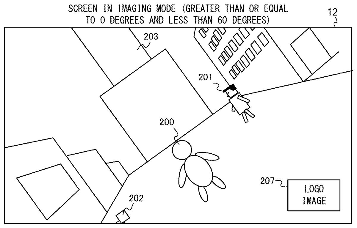
FIG. 9is an example non-limiting diagram showing an example of an image displayed in the imaging mode. As shown inFIG. 9, in the imaging mode, a part of the image displayed in the game mode is not displayed. Specifically, the physical strength indication206representing a state of the game is not displayed in the imaging mode. In the game mode, a dialogue (texts) uttered by the player character200or the NPC201,202may be displayed. Furthermore, for example, when the player character200is positioned at a certain place in the virtual space, texts may be displayed on the screen. The text thus displayed according to the state of the game in the game mode, is not displayed when the game mode has been switched to the imaging mode. Also in the imaging mode, the physical strength indication206representing a state of a game, or texts such as a dialogue displayed according to the state of the game may be displayed.
In the imaging mode, a logo image207, which is not displayed in the game mode, is displayed. The logo image207is displayed, for example, in the lower right portion of the screen. The position of the logo image207may be changed to any of the lower left portion, the lower right portion, the upper right portion, and the upper left portion of the screen according to an operation performed by a player. Furthermore, according to an operation performed by a player, the logo image207may not be displayed. An image, other than the logo image, which is not displayed in the game mode may be displayed in the imaging mode. For example, an explanation of an operation in the imaging mode may be displayed.
An image displayed in the imaging mode as shown inFIG. 9is generated based on the virtual camera disposed in the virtual space. In the imaging mode, the position and the orientation of the virtual camera are changed according to an operation performed by a player.
FIG. 10is an example non-limiting diagram showing rotation of the virtual camera in a roll direction in the imaging mode. In the virtual space, an XYZ orthogonal coordinate system which is fixed with respect to the virtual space is set. For example, the Y-axis extends upward in the virtual space. The X-axis and the Z-axis are set so as to be perpendicular to the Y-axis. A ground object is disposed on the XZ-plane. In the game mode, the player character200and the NPCs move on the ground object.
As shown inFIG. 10, a virtual camera VC is set in the virtual space. For the virtual camera VC, an XcYcZc orthogonal coordinate system which is fixed with respect to the virtual camera VC is set. The Xc-axis extends in the rightward direction of the virtual camera VC. The Yc-axis extends in the upper direction of the virtual camera VC. The Zc-axis extends in the line-of-sight direction (imaging direction) of the virtual camera VC. In the imaging mode, the virtual camera VC rotates around the Zc-axis (in the roll direction) according to an operation performed by a player. For example, the virtual camera VC rotates in the roll direction according to an operation on the ZL-button39of the left controller3or the ZR-button61of the right controller4. In a specific scene, rotation in the roll direction may be restricted.
FIG. 11is an example non-limiting diagram showing an example of an image obtained when the virtual camera VC is rotated in the roll direction (clockwise direction) in the imaging mode.FIG. 12is an example non-limiting diagram showing an example of an image obtained when the virtual camera VC is further rotated in the roll direction (clockwise direction) in the state shown inFIG. 11.
When, for example, the ZL-button39is pressed in the imaging mode, the virtual camera VC rotates in the roll direction (clockwise direction). When, for example, the ZR-button61is pressed in the imaging mode, the virtual camera VC rotates in the roll direction (counterclockwise direction). The game system1determines whether or not the ZL-button39or the ZR-button61has been pressed, at predetermined time intervals (for example, at intervals of 1/60 seconds). In a case where the ZL-button39or the ZR-button61has been pressed, the virtual camera VC is rotated by a predetermined angle (for example, 1° to 2°) in the roll direction (clockwise direction or counterclockwise direction). The game system1generates an image of the virtual space which is viewed from the virtual camera VC having been rotated, and displays the generated image on the display12.
As shown inFIG. 11, the image of the virtual space which is viewed from the virtual camera VC having been rotated in the roll direction (clockwise direction) is displayed on the display12. InFIG. 11, the entirety of the image has been rotated in the counterclockwise direction (the virtual camera VC has been rotated in the clockwise direction). Meanwhile, the logo image207displayed in the lower right portion of the display12is not rotated. At this time, when an operation is performed on the record button37, the image obtained by the entirety of the image being rotated in the counterclockwise direction as shown inFIG. 11is stored as a snapshot image together with the rotation information of the image in a storage medium (for example, flash memory84). At this time, information representing “no rotation” is stored as the rotation information of the image.
When the ZL-button39is further pressed in the state shown inFIG. 11, the virtual camera VC is further rotated in the roll direction (clockwise direction) (FIG. 12). Thus, the entirety of the image is further rotated in the counterclockwise direction as shown inFIG. 12. At this time, the logo image207displayed in the lower right portion of the display12is also rotated by 90 degrees in the counterclockwise direction. At this time, when an operation is performed on the record button37, an image obtained by the entirety of the image being rotated in the counterclockwise direction as shown inFIG. 12is stored as a snapshot image together with the rotation information of the image in the storage medium. Specifically, information representing “90 degrees rotation in the clockwise direction” is stored as the rotation information of the image.
Whether the information representing “no rotation” is stored as the rotation information as shown inFIG. 11or the information representing “90 degrees rotation in the clockwise direction (or 90 degrees rotation in the counterclockwise direction)” is stored as the rotation information as shown inFIG. 12” is determined according to a rotation angle of the virtual camera VC in the roll direction.
FIG. 13is an example non-limiting diagram showing an example of a criterion for determining the rotation information of an image. As shown inFIG. 13, in the plane perpendicular to the Zc-axis of the virtual camera VC, an angle r between the Yc-axis in the upward direction of the virtual camera VC and the Y-axis in the upward direction of the virtual space is calculated. The rotation in the counterclockwise direction is represented by a positive rotation angle, and the rotation in the clockwise direction is represented by a negative rotation angle. The angle r may be varied in the range from “−90 degrees” to “90 degrees”. That is, in the exemplary embodiment, the virtual camera VC is able to rotate in the roll direction in the range from “−90 degrees” to “90 degrees”. In another exemplary embodiment, the virtual camera VC may be rotated in the roll direction in the range from “−180 degrees to “180 degrees”.
The virtual camera VC may be rotated in the pitch direction (in such a direction as to view the virtual space from thereabove or view the virtual space from therebelow) as described below. When the virtual camera VC is rotated in the pitch direction, the Y-axis of the virtual space is projected onto the plane perpendicular to the Zc-axis, and an angle between the Yc-axis and the projected Y-axis is calculated as the angle r.
In a case where, for example, the angle r between the Yc-axis in the upward direction of the virtual camera VC and the Y-axis in the upward direction of the virtual space is less than “−60 degrees”, the information representing “90 degrees rotation in the clockwise direction” is determined as the rotation information. That is, in a case where the virtual camera VC is rotated in the clockwise direction by an angle greater than 60 degrees (that is, the entirety of the image displayed on the display12is rotated in the counterclockwise direction by an angle greater than 60 degrees), the information representing “90 degrees rotation in the clockwise direction” is determined as the rotation information. In this case, the logo image207is rotated by 90 degrees in the counterclockwise direction on the screen.
Furthermore, in a case where, for example, the angle r is greater than “60 degrees”, the information representing “90 degrees rotation in the counterclockwise direction” is determined as the rotation information. That is, in a case where the virtual camera VC is rotated in the counterclockwise direction by an angle greater than 60 degrees (that is, the entirety of the image displayed on the display12is rotated in the clockwise direction by an angle greater than 60 degrees), the information representing “90 degrees rotation in the counterclockwise direction” is determined as the rotation information. In this case, the logo image207is rotated by 90 degrees in the clockwise direction on the screen.
When the angle r is not less than “−60 degrees” and not greater than “60 degrees”, the information representing “no rotation” is determined as the rotation information. In this case, the logo image207is not rotated on the screen.
The rotation information determined based on the angle r is stored together with the image displayed on the screen, in the storage medium, according to an operation on the record button37.
FIG. 14is an example non-limiting diagram showing an example of an image obtained when the virtual camera VC is further rotated in the roll direction (clockwise direction) in the state shown inFIG. 12.FIG. 15is an example non-limiting diagram showing a state where the display12is held so as to be longitudinally elongated when the image shown inFIG. 14is displayed.
When the ZL-button39is further pressed in the state shown inFIG. 12, the virtual camera VC is further rotated in the roll direction (clockwise direction) (FIG. 14). As shown inFIG. 14, the logo image207displayed in the lower right portion of the display12does not change from the state shown inFIG. 12. As shown inFIG. 14, an image having been rotated by 90 degrees in the counterclockwise direction in the state shown inFIG. 9is displayed on the display12.
At this time, when an operation is performed on the record button37, the image shown inFIG. 14is stored together with the rotation information of the image as a snapshot image in the storage medium. At this time, the information representing “90 degrees rotation in the clockwise direction” is stored as the rotation information of the image.
As shown inFIG. 14andFIG. 15, when the virtual camera VC is rotated in the roll direction by 90 degrees, the image is longitudinally elongated. A part of the tower object203, which is not displayed in the laterally elongated image shown inFIG. 9, is displayed inFIG. 14andFIG. 15. Furthermore, the building object205displayed on the left side of the screen inFIG. 9is not displayed inFIG. 14andFIG. 15. That is, in a case where the virtual camera VC is rotated in the roll direction by 90 degrees, an image that is wide in the up-down direction of the virtual space and is narrow in the left-right direction thereof as compared to a case where the virtual camera VC is not rotated, is displayed. Thus, in the imaging mode, by the virtual camera VC being rotated in the roll direction, an image including the player character200and the entirety of the tower object203is displayed, and the image is able to be stored in the storage medium as a snapshot image according to an operation on the record button37.
(Display of Snapshot Image on Another Device)
The snapshot image stored in storage medium according to an operation on the record button37is able to be displayed on another device (for example, smartphone). For example, the game system1and the smartphone are connected to each other by a wired or wireless connection, and both the snapshot image and the rotation information are transmitted to the other device. The snapshot image and the rotation information thereof, which are generated by the game system1, are able to be copied to another device through a storage medium that is detachably mounted to the game system1and the other device. In a case where the snapshot image is displayed on the other device, the snapshot image is rotated according to the rotation information, and displayed.
FIG. 16is an example non-limiting diagram showing an example of the snapshot image, shown inFIG. 14, displayed on a smartphone. As shown inFIG. 16, the smartphone has a longitudinally elongated screen. In a case where the information representing “90 degrees rotation in the clockwise direction” is stored as the rotation information of the image, the smartphone rotates the snapshot image by 90 degrees in the clockwise direction, based on the rotation information, and displays the rotated image. Thus, the longitudinally elongated image that meets the screen of the smartphone is able to be displayed on the smartphone.
As described above, in the exemplary embodiment, switching to the imaging mode is performed during the game according to an operation performed by a player. In the imaging mode, the state of the object in the virtual space is not updated. In the imaging mode, the virtual camera VC rotates around the axis of the line-of-sight direction of the virtual camera according to an operation performed by the player. The image (snapshot image) of the virtual space based on the virtual camera and the rotation information, of the image, which is determined according to the rotation of the virtual camera around the axis of the line-of-sight direction are stored in the storage medium according to an instruction from the player. Since both the rotation information and the snapshot image are stored, when the snapshot image is displayed on another device, the image is able to be rotated according to the rotation information, and displayed.
Thus, since one scene of a game performed by the game system1is stored, together with the rotation information of the image, as a snapshot image, for example, the image is able to be displayed as a longitudinally elongated image on a smartphone having a longitudinally elongated screen. For example, an image stored in the game system1is able to be used as a wall paper (background image) of a smartphone.
In a case where a snapshot image stored in the game system1is displayed on the display12of the game system1, the game system1displays the image without rotating the image. That is, in a case where, for example, the image shown inFIG. 14is stored as the snapshot image in the flash memory84, when the stored image is displayed on the display12, the image shown inFIG. 14is displayed. This is because the display12is able to be held and oriented so as to be longitudinally elongated. Furthermore, in a case where, for example, the stored snapshot image is displayed on an external stationary monitor, the game system1may rotate the snapshot image by 90 degrees and display the rotated image, or may display the snapshot image without rotating the image.
In a case where the other device is not able to process the rotation information (for example, in a case where the other device is not supported under the EXIF), the other device displays the snapshot image without rotating the image.
FIG. 17is an example non-limiting diagram showing an example of a snapshot image displayed on another apparatus which cannot process the rotation information.
As shown inFIG. 17, the other device has a longitudinally elongated screen. The other device is not able to process the rotation information stored together with the snapshot image and is not able to rotate the snapshot image. Therefore, the other device displays the snapshot image as a laterally elongated image on the screen. For example, the other device reduces the snapshot image in the lateral direction and the longitudinal direction and displays the resultant image on the screen as shown inFIG. 17.
(Other Operation in Imaging Mode)
Next, an operation, other than rotation of the virtual camera VC in the roll direction, which is able to be performed in the imaging mode will be described.
In the exemplary embodiment, the virtual camera VC is able to rotate in the pitch direction (around the Xc-axis) and the yaw direction (around the Yc-axis) as well as in the roll direction (around the Zc-axis).FIG. 18is an example non-limiting diagram showing rotation of the virtual camera VC in the pitch direction and the yaw direction.
For example, the virtual camera VC rotates in the pitch direction and the yaw direction in the imaging mode according to an operation on the analog stick52of the right controller4. For example, as shown inFIG. 18, when the left-right direction is input on the analog stick52, the virtual camera VC rotates around the Yc-axis while the gaze point of the virtual camera VC is fixed onto the player character200. At this time, the position of the virtual camera VC is also changed. For example, the virtual camera VC moves on a circle, around the player character200, which is parallel to the XZ plane according to the input of the left-right direction on the analog stick52.
Furthermore, as shown inFIG. 18, when the up-down direction is input on the analog stick52, the virtual camera VC rotates around the Xc-axis while the gaze point of the virtual camera VC is fixed onto the player character200. At this time, the position of the virtual camera VC is also changed. For example, the virtual camera VC moves on an arc of a sector of a circle around the player character200on the plane perpendicular to the XZ plane according to input of the up-down direction on the analog stick52.
Thus, the virtual camera VC rotates also in the pitch direction and the yaw direction in the imaging mode according to an operation performed by a player. Therefore, the player is allowed to store, as the snapshot image, an image of the virtual space viewed at a desired angle.
Also in the game mode, as shown inFIG. 18, the virtual camera VC rotates in the pitch direction and the yaw direction according to an operation on the analog stick52of the right controller4. Therefore, also in the game mode, a player is allowed to play a game while viewing the virtual space at a desired angle. However, in the game mode, the virtual camera VC does not rotate in the roll direction according to an operation performed by a player. Also in the game mode, the virtual camera VC may rotate in the roll direction according to an operation performed by a player. Furthermore, in a specific scene, rotation in the pitch direction and the yaw direction may be restricted.
In the imaging mode, the gaze point or the position (viewpoint) of the virtual camera VC may be changed in the virtual space according to an operation on the analog stick32of the left controller3. In the imaging mode, an angle of view of the virtual camera VC may be changed according to an operation performed by a player.
Furthermore, in the imaging mode, for example, setting of zooming (zooming in or zooming out) of the virtual camera VC may be performed according to an operation on a predetermined button of the right controller4.
(Selection of Filter)
Furthermore, a player is allowed to select a filter in the imaging mode. The “filter” is used to change a display manner for an image displayed on the display12. When the filter is selected, a predetermined process is performed on an image based on the virtual camera VC, and the display manner for the image is changed. For example, in the exemplary embodiment, “blur”, “sepia”, “black-and-white”, “low resolution”, “line drawing”, “dot drawing”, “fish eye camera”, “silhouette”, and the like are prepared for the filter.
The “blur” filter is used to blur an image. The “sepia” filter is used to process the entirety of the image into a sepia image. The “black-and-white” filter is used to display the entirety of the image as a black-and-while image.
The “low resolution” filter is used to generate an image obtained based on the virtual camera VC such that the resolution of the image is lower than a normal resolution (resolution of an image in the game mode).
The “line drawing” filter is used to generate an image only by lines. When the “line drawing” filter is selected, an edge extraction process is performed on an image generated based on the virtual camera VC. The “dot-drawing” filter is used to generate an image only by dots. When the “dot-drawing” filter is selected, a feature (point) is extracted from an image generated based on the virtual camera VC, to generate the image for which the feature has been extracted.
The “fish eye camera” filter is used to generate a deformed image as obtained when the virtual space is viewed with a fish eye camera. When the “fish eye camera” filter is selected, an image generated based on the virtual camera VC is deformed.
The “silhouette” filter is used to display a silhouette image. For example, a three-dimensional image in which each pixel of the image is associated with a depth value, based on the virtual camera VC, is generated. The silhouette image is generated by using the depth value of the generated three-dimensional image.
Thus, the “filter” is used to perform a predetermined process (for example, process of deforming an image, process of blurring an image, process of changing a color tone of an image, process of changing a brightness of an image, process of changing a resolution of an image) on an image generated based on the virtual camera VC, and used to perform a process (for example, process of extracting a depth value, process of extracting an edge) of extracting a feature of a three-dimensional image generated based on the virtual camera VC.
For example, a player is allowed to select a filter according to an operation on a predetermined button of the left controller3. When the filter is selected, an image having been subjected to the filter process (process of deforming an image, process of blurring an image, process of changing a color tone of an image, process of changing a brightness of an image, process of changing a resolution, process of extracting a feature of an image) according to the selected filter is displayed on the display12. According to an operation being performed on the record button37, the image having been subjected to the filter process, and the rotation information thereof are stored in the storage medium.
When the filter process is performed on an image of the virtual space based on the virtual camera VC, the display manner for the logo image207is not changed. Specifically, an image having been subjected to the filter process is rendered, and a predetermined logo image207is rendered so as to overlap the image. Thus, an image in which the image having been subjected to the filter process and the logo image207subjected to no filter process overlap each other, is generated and displayed. When the filter is selected, a display manner for images including the logo image207may be changed. Furthermore, an object corresponding to the logo image207is disposed in the virtual space and an image of the object is taken by the virtual camera, whereby an image of the virtual space including the logo image207may be generated.
(Detailed Description of Process)
Next, a process performed by the game system1will be described in detail. Firstly, data stored in the game system1will be described. Thereafter, information processing performed by the game system1will be described in detail.
FIG. 19is an example non-limiting diagram showing an example of data stored in the DRAM85of the game system1.FIG. 20is an example non-limiting diagram showing an example of data stored in the flash memory84of the game system1.
As shown inFIG. 19, in the DRAM85of the game system1, a game program D200, an imaging control program D201, virtual camera data D202, image data D203, rotation information D204, filter information D205, mode information D206, player character information D207, and NPC information D208are stored. In the DRAM85of the game system1, various data and programs other than those shown inFIG. 19are stored.
The game program D200is a program for performing a game according to the exemplary embodiment, and is previously stored in an external storage medium mounted in the slot23. The game program D200is loaded from the external storage medium to the DRAM85when the game is started.
The imaging control program D201is a program for storing, in a storage medium (for example, flash memory84), a snapshot image and the rotation information in the imaging mode. The imaging control program D201is previously stored in the main body apparatus2(for example, flash memory84). The imaging control program D201is loaded from the flash memory84to the DRAM85when, for example, the main body apparatus2is powered on.
The virtual camera data D202includes orientation information and position information. The orientation information of the virtual camera data D202includes a rotation angle of the virtual camera VC in the roll direction, a rotation angle thereof in the pitch direction, and a rotation angle thereof in the yaw direction. The position information of the virtual camera data D202represents a position, a gaze point, and the like of the virtual camera VC in the virtual space.
The image data D203represents an image of the virtual space generated based on the virtual camera VC. In the imaging mode, when the filter is applied, image data of an image to which the filter has been applied is stored as the image data D203. In the imaging mode, when the logo image207is added, an image obtained by the logo image207being added to an image of the virtual space generated based on the virtual camera VC is stored as the image data D203.
The rotation information D204is data that represents the rotation information of the image data D203. For example, as the rotation information D204, information representing “no rotation”, information representing “90 degrees rotation in the clockwise direction”, and information representing “90 degrees rotation in the counterclockwise direction” are stored.
The filter information D205represents a kind of a selected filter.
The mode information D206is data that indicates whether the mode is the game mode or the imaging mode. In the mode information D206, a value representing the game mode is initially stored.
The player character information D207is data that represents a state of the player character200. Specifically, the player character information D207includes data that represents a position, an action, a physical strength value (or remaining lives) of the player character200.
The NPC information D208is data that represents a state of an NPC (non-player character). Specifically, the NPC information D208includes data that represents a position and an action of each non-player character.
Furthermore, as shown inFIG. 20, snapshot image data D300is stored in the flash memory84of the game system1. The snapshot image data D300is copied from data in the DRAM85at a time when the record button37is pressed. The snapshot image data D300is the same data as the image data D203obtained at a time when the record button37is pressed. Rotation information D301is added to the snapshot image data D300. The rotation information D301is the same data as the rotation information D204obtained at a time when the record button37is pressed. In the flash memory84, the image data D203and the rotation information D204thereof each of which is obtained at a time when the record button37is pressed, are stored. For example, the image data D203and the rotation information D204thereof each of which is obtained at a certain time are stored as the snapshot image data D300and the rotation information D301, and the image data D203and the rotation information D204thereof each of which is obtained at another time are stored as the snapshot image data D310and the rotation information D311. In addition to the rotation information, information indicating a date and time when image has been taken, information indicating a resolution, and the like are stored as additional information of the snapshot image.
Next, a process performed by the game system1will be described in detail.FIG. 21is an example non-limiting flow chart showing in detail a process performed by the game system1. The process shown inFIG. 21is performed by the game program D200or the imaging control program D201being executed by the processor81of the game system1. In the game system1, when an instruction for executing the game according to the exemplary embodiment is made, the process shown inFIG. 21will start.
As shown inFIG. 21, the processor81obtains operation data representing an operation performed on each button or the analog stick of the controller (step S1). Subsequently, the processor81executes a game process based on the operation data (step S2).
Specifically, in the game process, the processor81updates a position of the player character200in the virtual space according to, for example, an operation on the analog stick32. The processor81causes the player character200to jump according to, for example, an operation on the A-button53of the right controller4. For example, when the player character200contacts with the NPC, the processor81reduces the physical strength value (or remaining lives) of the player character200. The processor81stores data corresponding to a position, an action, and a physical strength value of the player character200, as the player character information D207, in the DRAM85. Furthermore, the processor81updates a position of the NPC (non-player character), or causes the NPC to perform a predetermined action. The processor81stores data corresponding to a position and an action of the NPC, as the NPC information D208, in the DRAM85. The processor81updates a position of the virtual camera VC or rotates the virtual camera VC in the pitch direction or the yaw direction according to the operation data. The processor81stores data corresponding to a position and an orientation of the virtual camera VC, as the virtual camera data D202, in the DRAM85. After these processes have been performed, the processor81generates an image of the virtual space based on the virtual camera VC, and stores the generated image as the image data D203in the DRAM85. The processor81displays, on, for example, the display12, an image obtained by the physical strength indication206representing a physical strength value of the player character200being added to the image generated based on the virtual camera VC.
Next, the processor81determines whether or not an instruction for switching to the imaging mode has been made, according to the operation data (step S3). In a case where an instruction for switching to the imaging mode is not made (step S3: NO), the processor81executes the process step of step S1again. The process of step S1to step S3is a process in the game mode. While an instruction for switching to the imaging mode is not made, the process of step S1to step S3is repeatedly performed at predetermined time intervals (for example, at intervals of 1/60 seconds). In a case where, while the process of step S1to step S3is performed, a player makes an instruction for ending the game play or the game is over, the processor81ends the process shown inFIG. 21.
In a case where, while the process of step S1to step S3is performed, the record button37is pressed, the processor81stores, in the flash memory84, an image displayed on the display12at the time of the pressing. In this case, the physical strength indication206shown inFIG. 8and texts representing a dialogue of the player character200or the NPC are also stored although the physical strength indication206and the texts are not displayed in the imaging mode.
In a case where an instruction for switching to the imaging mode has been made (step S3: YES), the processor81sets the imaging mode (step S4). Specifically, the processor81stores a value representing the imaging mode, in the mode information D206. In a case where the value representing the imaging mode is stored in the mode information D206, states (positions, actions, and the like) of the player character200and the NPCs are not updated. That is, in the imaging mode, the player character information D207and the NPC information D208are not updated. In a case where the value representing the imaging mode is stored in the mode information D206, measurement of the elapse of time since the start of the game is also stopped.
Subsequent to step S4, the process of step S5to step S13is performed. The process of step S5to step S13is a process in the imaging mode. The process of step S5to step S13is repeatedly performed at predetermined time intervals (for example, at intervals of 1/60 seconds). Also while the process of step S5to step S13is performed, the processor81repeatedly obtains the operation data.
In step S5, the processor81determines whether or not an operation for rotation in the roll direction has been performed. Specifically, the processor81determines whether or not an operation on the ZL-button39or the ZR-button61has been performed. In a case where it is determined that the operation for rotation in the roll direction has been performed (step S5: YES), the processor81performs a rotation process (step S6). The rotation process in step S6is a process for rotating the virtual camera VC in the roll direction. Hereinafter, the rotation process in step S6will be described in detail.FIG. 22is an example non-limiting flow chart showing in detail the rotation process in step S6.
As shown inFIG. 22, the processor81rotates the virtual camera VC in the roll direction (axis of the line-of-sight direction) (step S21). For example, in a case where the ZL-button39is pressed, the processor81rotates the virtual camera VC in the clockwise direction by a predetermined angle. In a case where the ZR-button61is pressed, the processor81rotates the virtual camera VC in the counterclockwise direction by a predetermined angle. The processor81stores the orientation information of the virtual camera VC having been rotated, as the virtual camera data D202, in the DRAM85.
Next, the processor81determines whether or not the rotation angle r of the virtual camera VC in the roll direction is greater than or equal to a predetermined threshold value (step S22). For example, the predetermined threshold value may be “60 degrees”. In a case where the rotation angle r is greater than or equal to the predetermined threshold value (60 degrees) (step S22: YES), the processor81determines “90 degrees rotation in the counterclockwise direction”, and stores information representing “90 degrees rotation in the counterclockwise direction”, as the rotation information D204, in the DRAM85(step S23).
In a case where the determination in step S22is NO, the processor81determines whether or not the rotation angle r is less than or equal to a predetermined threshold value (step S24). For example, the predetermined threshold value may be “−60 degrees”. In a case where the rotation angle r is less than or equal to the predetermined threshold value (−60 degrees) (step S24: YES), the processor81determines “90 degrees rotation in the clockwise direction”, and stores information representing “90 degrees rotation in the clockwise direction”, as the rotation information D204, in the DRAM85(step S25).
In a case where the determination in step S24is NO, the processor81determines “no rotation”, and stores information representing “no rotation”, as the rotation information D204, in the DRAM85(step S26).
In a case where the process step of step S23, step S25, or step S26is performed, the processor81ends the process shown inFIG. 22.
Returning toFIG. 21, in a case where it is determined that the operation for rotation in the roll direction is not performed (step S5: NO), the processor81determines whether or not another operation has been performed (step S7). The “another operation” represents an operation other than rotation of the virtual camera VC in the roll direction, and is, for example, an operation of moving the virtual camera VC, an operation of rotating the virtual camera VC in the pitch direction or the yaw direction, an operation of selecting a filter, an operation of changing a position of the logo image207, or an operation of selecting non-display of the logo image207.
In a case where it is determined that any of the other operations has been performed (step S7: YES), the processor81performs a process according to the operation (step S8).
For example, in a case where an operation of moving the virtual camera VC is performed, the processor81moves the virtual camera VC in the virtual space, or changes the gaze point of the virtual camera VC. In a case where an operation of rotating the virtual camera VC in the pitch direction or the yaw direction is performed, the processor81rotates the virtual camera VC in the pitch direction or the yaw direction. The processor81stores the virtual camera data D202in the DRAM85according to the results of the process. In a case where an operation of selecting a filter is performed, the processor81sets a value corresponding to the selected filter, in the filter information D205. In a case where a filter is selected, the processor81performs a filter process corresponding to the selected filter, on the image generated based on the virtual camera VC, in the subsequent image generation process. In a case where an operation of changing a position of the logo image207is performed, the processor81changes the position at which the logo image207is displayed. In a case where an operation of selecting non-display of the logo image207is performed, the processor81sets the logo image207so as not to display the logo image207.
When the process step of the step S6has been performed, when the process step of step S8has been performed, or when the determination in step S7is NO, the processor81performs the image generation process (step S9).
Specifically, in step S9, the processor81generates an image of the virtual space based on the virtual camera VC.
In a case where a filter is selected in step S8, the processor81performs a filter process corresponding to the selected filter, on the image generated based on the virtual camera VC. For example, when the “blur” filter is selected, the processor81performs blur process on the image generated based on the virtual camera VC, whereby an image to which the “blur” filter has been applied is generated. In a case where the “line drawing” filter is selected, a process (process of extracting a feature) of extracting an edge of the image generated based on the virtual camera VC is performed, whereby an image to which the “line drawing” filter has been applied is generated. In a case where the “fish eye camera” filter is selected, the processor81deforms the image generated based on the virtual camera VC, whereby an image to which the “fish eye camera” filter has been applied is generated. In a case where the “silhouette” filter is selected, the processor81generates a silhouette image by using a depth value of the image generated based on the virtual camera VC.
The image generated based on the virtual camera VC (image to which the filter has not yet been applied) or an image obtained by the filter process having been performed on the image generated based on the virtual camera VC may be referred to as “virtual camera image”.
The processor81adds the logo image207which is previously stored, to the generated “virtual camera image”, and stores the resultant image as the image data D203in the DRAM85. At this time, the processor81rotates the logo image207according to the rotation information D204set in the rotation process of step S6, and adds the logo image207having been rotated. For example, in a case where the information representing “90 degrees rotation in the clockwise direction” is set as the rotation information D204, the processor81rotates the logo image207by 90 degrees in the counterclockwise direction, and adds the resultant image to the “virtual camera image”. In a case where the information representing “90 degrees rotation in the counterclockwise direction” is set as the rotation information D204, the processor81rotates the logo image207by 90 degrees in the clockwise direction, and adds the resultant image to the “virtual camera image”. In a case where the information representing “no rotation” is set as the rotation information D204, the processor81adds the logo image207to the “virtual camera image” without rotating the logo image207. In a case where non-display of the logo image207is set in step S8, the logo image207is not added. The physical strength indication206which is added in the game process of step S2in the game mode is not added. Texts, representing a dialogue of the player character200or the NPC, which are displayed in the game mode are not rendered in the image generation process of step S9.
Subsequent to step S9, the processor81performs an image output process (step S10). Specifically, the processor81outputs, to the display12, the image data D203stored in the DRAM85in step S9.
Next, the processor81determines whether or not the record button37has been pressed (step S11). In a case where the record button37has been pressed (step S11: YES), the processor81stores, in the flash memory84, the image data D203and the rotation information D204stored in the DRAM85. In the flash memory84, the image data D203is stored as the snapshot image data D300, and the rotation information D204is stored as the rotation information D301.
The process step of step S12is performed by the processor81executing the imaging control program D201.
When the process step of step S12has been performed, or when the determination in step S11is NO, the processor81determines whether or not the imaging mode is to be ended (step S13). In a case where it is determined that the imaging mode is not to be ended, that is, in a case where a player does not make an instruction for ending the imaging mode (step S13: NO), the processor81performs the process step of step S5again.
Meanwhile, in a case where it is determined that the imaging mode is to be ended, that is, in a case where a player makes an instruction for ending the imaging mode (step S13: YES), the processor81stores information representing the game mode, in the mode information D206, and performs the process step of step S1again. Thus, switching from the imaging mode to the game mode is performed. Thereafter, the process of step S1to step S3is repeated, and the game which has been temporarily stopped is restarted. That is, the game is restarted from a state immediately preceding switching to the imaging mode. This is the end of the description with reference toFIG. 21.
The processes shown inFIG. 21andFIG. 22are merely examples. InFIG. 21andFIG. 22, the order in which the steps are performed may be changed, another step may be added, or a part of the steps may be omitted. Furthermore, the numerical values used in the steps are merely examples, and other values may be used. For example, although “60 degrees” is used as the predetermined threshold value in step S22, the predetermined threshold value may be, for example, “45 degrees” or “75 degrees”. Furthermore, although “−60 degrees” is used as the predetermined threshold value in step S24, the predetermined threshold value may be, for example, “−45 degrees” or “−75 degrees”.
As described above, in the exemplary embodiment, in a case where a player performs an operation for switching to the imaging mode during the game play (step S1to step S3), the game mode is switched to the imaging mode (step S4). In the imaging mode, actions of all the objects, in the virtual space, including the player character200and the NPCs are stopped. In the imaging mode, the virtual camera VC is rotated in the roll direction according to an operation performed by a player (step S6). In a case where the rotation angle (absolute value of rotation angle) of the virtual camera VC in the roll direction is greater than or equal to a predetermined threshold value (YES in step S22or YES in step S24), “90 degrees rotation in the counterclockwise direction or clockwise direction” is determined as the rotation information of the image (step S23or step S25). According to an instruction from a player, the image (virtual camera image) generated based on the virtual camera VC is stored together with the rotation information of the image, in the storage medium, at the time of the instruction (step S12).
Thus, in the exemplary embodiment, the image of the virtual space is able to be stored as an image which has been rotated by 90 degrees, and, for example, an image displayed as a laterally elongated image in a normal game play is able to be stored as a longitudinally elongated image. When the stored image is displayed on another device, the image is able to be displayed as a longitudinally elongated image.
In the exemplary embodiment, the progress of the game is temporarily stopped in the imaging mode, and, in that state, the virtual camera VC is able to be rotated in the pitch direction or the yaw direction or moved. Thus, an image of the virtual space which is viewed at a desired angle and a desired position can be taken, and various images during the game are able to be stored.
In the exemplary embodiment, by a filter being selected, a display manner for an image during the game is able to be changed and the image is able to be taken.
(Modification)
Although the exemplary embodiment has been described above, various modifications may be made in other embodiments.
For example, in the above-described exemplary embodiment, the virtual camera VC is rotated around the Zc-axis which is fixed with respect to the virtual camera VC. In another exemplary embodiment, the virtual camera VC may be rotated around an axis which is different from the Zc-axis and is an axis (for example, axis parallel to the Zc-axis, or axis which is not perfectly parallel to the Zc-axis and deviated by a predetermined angle relative to the Zc-axis) of the line-of-sight direction of the virtual camera VC. That is, the axis of the line-of-sight direction of the virtual camera VC may be perfectly identical to the Zc-axis, may be parallel to the Zc-axis, or may be deviated by a predetermined angle relative to the Zc-axis (another axis having a component in the Zc-axis direction). The virtual camera VC is rotated around the axis of the line-of-sight direction, and the rotation information may be set according to an amount of rotation around the axis of the line-of-sight direction.
In the above-described exemplary embodiment, the game program D200is stored in an external storage medium mounted in the slot23, and the imaging control program D201is stored in the flash memory84that is previously provided in the main body apparatus2. The processor81determines the rotation information of an image by executing the game program D200, and the processor81stores the image and the rotation information of the image in the flash memory84by executing the imaging control program D201. In another exemplary embodiment, the imaging control program D201may be a part of the game program D200. That is, a program including the game program D200and the imaging control program D201may be stored in an external storage medium. Furthermore, a program including the game program D200and the imaging control program D201may be previously stored in the flash memory84. Moreover, a program including the game program D200and the imaging control program D201may be downloaded from an external device.
In the above-described exemplary embodiment, the virtual camera VC is able to be rotated in the pitch direction and the yaw direction, according to an operation performed by a player, in the game mode. In another exemplary embodiment, rotation of the virtual camera VC in the pitch direction, in the yaw direction, and also in the roll direction may be prohibited in the game mode.
In the above-described exemplary embodiment, rotation of the virtual camera VC in the roll direction according to an operation performed by a player is not able to be performed in the game mode. In another exemplary embodiment, the virtual camera VC may be rotated in the roll direction (also in the pitch direction and the yaw direction) according to an operation performed by a player in the game mode. An image which is being displayed, and the rotation information, of the image, which is determined according to a rotation angle of the virtual camera VC in the roll direction may be stored in a storage medium, according to an operation on the record button37, during the game play.
In the above-described exemplary embodiment, a game in which the player character200is operated, according to an operation performed by a player, in the game mode, is assumed. In another exemplary embodiment, not only a game in which the player character200is operated according to an operation performed by a player, but also a game in which an object automatically moves in the virtual space regardless of an operation performed by a player, may be played. While such a game is being played, the game mode may be switched to the imaging mode. In the imaging mode, the virtual camera is rotated in the roll direction according to an operation performed by a player, and, according to an instruction from the player, an image as viewed from the virtual camera at the time of the instruction, and the rotation information of the image may be stored in a storage medium.
In the above-described exemplary embodiment, a still image is stored in a storage medium according to an operation on the record button37. In another exemplary embodiment, a moving image may be stored according to an operation performed by a player. For example, the virtual camera is rotated in the roll direction during a game play, and a moving image during the game, and the rotation information determined according to a rotation angle of the virtual camera in the roll direction may be stored in a storage medium according to an operation performed by the player.
In the above-described exemplary embodiment, an image displayed on the display12and the rotation information of the image are stored in the flash memory84according to an operation on the record button37. The image and the rotation information of the image may be stored in any storage medium according to an operation on the record button37. For example, an image and the rotation information of the image may be stored in an external storage medium mounted in the slot23or another slot according to an operation on the record button37. For example, in a case where the game system1is connected to a network (for example, the Internet) by a wired or wireless connection, an image and the rotation information of the image may be stored in a storage medium over the network according to an operation on the record button37.
In the above-described exemplary embodiment, an image of the virtual space is generated by using the virtual camera VC at predetermined time intervals (for example, at intervals of 1/60 seconds), the rotation information of the generated image is determined, and the image of the virtual space and the rotation information thereof are stored in the DRAM85. At a time when an operation is performed on the record button37, the image and the rotation information of the image, which are stored in the DRAM85, are stored in another storage medium. That is, an image of the virtual space is constantly generated, and the rotation information of the image is determined and temporarily stored each time the image is generated, and the temporarily stored image and the rotation information of the image are stored in a storage medium according to an operation being performed on the record button37. In another exemplary embodiment, an image of the virtual space may be generated by using the virtual camera VC at predetermined time intervals (for example, at intervals of 1/60 seconds) and, at a time when an operation is performed on the record button37, the rotation information of an image generated at the time may be determined. That is, in another exemplary embodiment, at a time when an operation is performed on the record button37, the rotation information of an image being displayed, is determined based on an orientation of the virtual camera at the time when the operation is performed on the record button37, and the image which is being displayed and the rotation information may be stored in the storage medium.
Furthermore, in the above-described exemplary embodiment, any of the information representing “no rotation”, the information representing “90 degrees rotation in the clockwise direction”, and the information representing “90 degrees rotation in the counterclockwise direction” is stored as the rotation information of an image. In another exemplary embodiment, any of information representing “180 degrees rotation”, information representing “90 degrees rotation, in the clockwise direction, followed by lateral inversion”, information representing “90 degrees rotation, in the counterclockwise direction, followed by lateral inversion”, information representing “no rotation and lateral inversion”, and information representing “no rotation and vertical inversion”, in addition to the information representing “no rotation”, the information representing “90 degrees rotation in the clockwise direction”, and the information representing “90 degrees rotation in the counterclockwise direction”, may be stored, as the rotation information of an image, based on the orientation of the virtual camera.
Furthermore, the game system described above is merely an exemplary one. The game program and the imaging control program may be executed by any information processing apparatus or an information processing system in which a plurality of devices are combined with each other. For example, the information processing apparatus may be a smartphone, a tablet terminal, a personal computer, a stationary game apparatus, or the like. The information processing system may include a plurality of devices connected to a network (for example, the Internet). The information processing apparatus or the information processing system controls an orientation of the virtual camera according to an operation performed by a player. The information processing apparatus or the information processing system may store, in a storage medium, an image of the virtual space as viewed from the virtual camera, and the rotation information of the image, according to an operation performed by a player.
While the exemplary embodiment has been described above, the foregoing description is in all aspects illustrative, and numerous other modifications and variations may be devised.
While certain example systems, methods, devices and apparatuses have been described herein, it is to be understood that the appended claims are not to be limited to the systems, methods, devices and apparatuses disclosed, but on the contrary, are intended to cover various modifications and equivalent arrangements included within the spirit and scope of the appended claims.
Claims
- A game system comprising: a storage medium;and at least one processor and a memory coupled thereto, wherein the at least one processor is configured to at least: control an object in a virtual space;control an orientation of a virtual camera in the virtual space, based on an operation performed by a player;generate an image of the virtual space based on the virtual camera, for display, at certain time intervals;and store, according to an instruction from a player, an image generated at a time of the instruction, and rotation information, of the image, determined based on an orientation of the virtual camera at the time of the instruction, in the storage medium.
- The game system according to claim 1 , wherein the at least one processor is further configured to: switch to an imaging mode, during a game play, based on an operation performed by a player, wherein in the imaging mode, an object in the virtual space is controlled so as not to update a state of the object, and the virtual camera is rotated at least around an axis of a line-of-sight direction, based on an operation performed by a player;and determine the rotation information, based on an amount of rotation of the virtual camera around the axis of the line-of-sight direction at the time of the instruction.
- The game system according to claim 2 , wherein, in a case where the amount of rotation becomes greater than or equal to a threshold value, the at least one processor is further configured to determine, as the rotation information, information indicating that an image stored in the storage medium is rotated by 90 degrees and displayed when the image is displayed.
- The game system according to claim 2 , wherein the at least one processor is further configured to add an additional image to at least a part of an image generated, and rotate and add the additional image when an amount of rotation of the virtual camera becomes greater than or equal to a threshold value, in the imaging mode.
- The game system according to claim 2 , wherein the at least one processor is further configured to change a display manner for at least a part of an image generated, according to an instruction from a player, in the imaging mode.
- The game system according to claim 5 , wherein the at least one processor is further configured to subject at least a part of an image generated to at least one of deforming the image, blurring the image, changing a color tone of the image, changing a brightness of the image, changing a resolution of the image, and extracting a feature of the image.
- The game system according to claim 2 , wherein the at least one processor is further configured to generate an image so as not to display a portion, of the image, which is displayed during the game play, in the imaging mode.
- The game system according to claim 1 , further comprising: a display having a laterally elongated or a longitudinally elongated screen;and a hand-held housing configured to support the display;wherein the at least one processor is further configured to display, on the display, an image generated.
- The game system according to claim 8 , further comprising an external output to output, to an outside, an image generated.
- A non-transitory storage medium having stored therein a game program executable by a computer of an information processing system, the game program, when executed, causing the computer to at least: control an object in a virtual space;control an orientation of a virtual camera in the virtual space, based on an operation performed by a player;generate an image of the virtual space based on the virtual camera, for display, at certain time intervals;and determine, based on an orientation of the virtual camera, rotation information of an image, of the virtual space, which is generated in the image generation and stored in a storage medium, the rotation information being used when the image is stored in the storage medium.
- The non-transitory storage medium having stored therein the game program according to claim 10 , the game program, when executed, causing the computer to further switch to an imaging mode, during a game play, based on an operation performed by a player, wherein when switching to the imaging mode has been performed, an object in the virtual space is controlled so as not to update a state of the object, in the object control, the virtual camera is rotated at least around an axis of a line-of-sight direction, based on an operation performed by a player, in the virtual camera control, and the rotation information is determined, in the rotation information determination, based on an amount of rotation of the virtual camera around the axis of the line-of-sight direction, the amount of rotation being obtained when the image is generated in the image generation.
- The non-transitory storage medium having stored therein the game program according to claim 11 , wherein, in the rotation information determination, in a case where the amount of rotation becomes greater than or equal to a threshold value, information indicating that the image is rotated by 90 degrees and displayed when the image is displayed, is determined as the rotation information.
- The non-transitory storage medium having stored therein the game program according to claim 11 , the game program causing the computer to further add an additional image to at least a part of an image generated in the image generation, and rotate and add the additional image when an amount of rotation of the virtual camera becomes greater than or equal to a threshold value, in the imaging mode.
- The non-transitory storage medium having stored therein the game program according to claim 11 , the game program, when executed, causing the computer to further change a display manner for at least a part of an image generated in the image generation, according to an instruction from a player, in the imaging mode.
- The non-transitory storage medium having stored therein the game program according to claim 14 , wherein, in the changing, at least a part of an image generated in the image generation is subjected to at least one of deforming the image, blurring the image, changing a color tone of the image, of changing a brightness of the image, of changing a resolution of the image, and of extracting a feature of the image.
- The non-transitory storage medium having stored therein the game program according to claim 11 , wherein, in the image generation, an image is generated so as not to display a portion, of the image, which is displayed during a game play, in the imaging mode.
- A game apparatus comprising: a storage medium;and at least one processor and a memory coupled thereto, wherein the at least one processor is configured to at least: control an object in a virtual space;control an orientation of a virtual camera in the virtual space, based on an operation performed by a player;generate an image of the virtual space based on the virtual camera, for display, at certain time intervals;and store, according to an instruction from a player, an image generated by the image generation at a time of the instruction, and rotation information, of the image, determined based on an orientation of the virtual camera at the time of the instruction, in the storage medium.
- The game apparatus according to claim 17 , wherein the at least one processor is further configured to: switch to an imaging mode, during a game play, based on an operation performed by a player, wherein in the imaging mode, an object in the virtual space is controlled so as not to update a state of the object, and the virtual camera is rotated at least around an axis of a line-of-sight direction, based on an operation performed by a player;and determine the rotation information, based on an amount of rotation of the virtual camera around the axis of the line-of-sight direction at the time of the instruction.
- A game processing method performed by an information processing system, the game processing method comprising: controlling an object in a virtual space;controlling an orientation of a virtual camera in the virtual space, based on an operation performed by a player;generating an image of the virtual space based on the virtual camera, for display, at certain time intervals;and storing, according to an instruction from a player, an image generated in the image generation at a time of the instruction, and rotation information, of the image, determined based on an orientation of the virtual camera at the time of the instruction, in a storage medium.
- The game processing method according to claim 19 , further comprising: switching to an imaging mode, during a game play, based on an operation performed by a player, wherein in the imaging mode, an object in the virtual space is controlled so as not to update a state of the object, in the object control, and the virtual camera is rotated at least around an axis of a line-of-sight direction, based on an operation performed by a player, in the virtual camera control;and determining the rotation information, based on an amount of rotation of the virtual camera around the axis of the line-of-sight direction at the time of the instruction.
- The game processing method according to claim 19 , further comprising: switching to an imaging mode, during a game play, based on an operation performed by a player, wherein in the imaging mode, an object in the virtual space is controlled so as not to update a state of the object, in the object control, and the virtual camera is rotated at least around an axis of a line-of-sight direction, based on an operation performed by a player, in the virtual camera control;and determining the rotation information, based on an amount of rotation of the virtual camera around the axis of the line-of-sight direction at the time of the instruction.
Disclaimer: Data collected from the USPTO and may be malformed, incomplete, and/or otherwise inaccurate.