U.S. Pat. No. 10,589,176
METHOD OF PROVIDING A VIRTUAL SPACE, MEDIUM FOR CAUSING A COMPUTER TO EXECUTE THE METHOD, AND SYSTEM FOR PROVIDING A VIRTUAL SPACE
AssigneeCOLOPL, INC.
Issue DateApril 5, 2019
Illustrative Figure
Abstract
A method of providing a virtual space. The method includes defining a virtual space by a processor. The method further includes displaying a field of view of the virtual space on a head mounted display device. The method further includes detecting, by the processor, a motion of the user wearing the head mounted display device. The method further includes determining, by the processor, a flying direction for an object in the virtual space in response to the detected motion. The method further includes flying, by the processor, the object within the virtual space in accordance with the flying direction. The method further includes moving, by the processor, the field of view in the flying direction.
Description
DETAILED DESCRIPTION Now, with reference to the drawings, embodiments of this disclosure are described in detail. In the following description, like components are denoted by like reference symbols. The same applies to the names and functions of those components. Therefore, detailed description of those components is not repeated. [Configuration of HMD System] With reference toFIG. 1, a configuration of a head mount display (HMD) system100is described.FIG. 1is a diagram of the configuration of the HMD system100according to at least one embodiment of this disclosure. In at least one aspect, the HMD system100is provided as a system for household use or a system for professional use. InFIG. 1, the HMD system100according to at least one embodiment of this disclosure includes an HMD device110, an HMD sensor120, a controller160, and a computer200. The HMD device110includes a monitor112and an eye gaze sensor140. The controller160includes a motion sensor130. In at least one aspect, the computer200can be connected to a network19and can communicate to/from a server150connected to the network19. In at least one aspect, the HMD device110may include a sensor114instead of the HMD sensor120. The HMD device110of at least one embodiment of this disclosure may be worn on a head of a user to provide a virtual space to the user during operation. More specifically, the HMD device110displays each of a right-eye image and a left-eye image on monitor112. When each eye of the user visually recognizes each image, the user may recognize the image as a three-dimensional image based on the parallax of both the eyes. The monitor112is achieved as, for example, a non-transmissive display device or a partially transmissive display device. In at least one aspect, the monitor112is arranged on a main body of the HMD device110so as to be positioned in front of both the eyes of the user. Therefore, when the ...
DETAILED DESCRIPTION
Now, with reference to the drawings, embodiments of this disclosure are described in detail. In the following description, like components are denoted by like reference symbols. The same applies to the names and functions of those components. Therefore, detailed description of those components is not repeated.
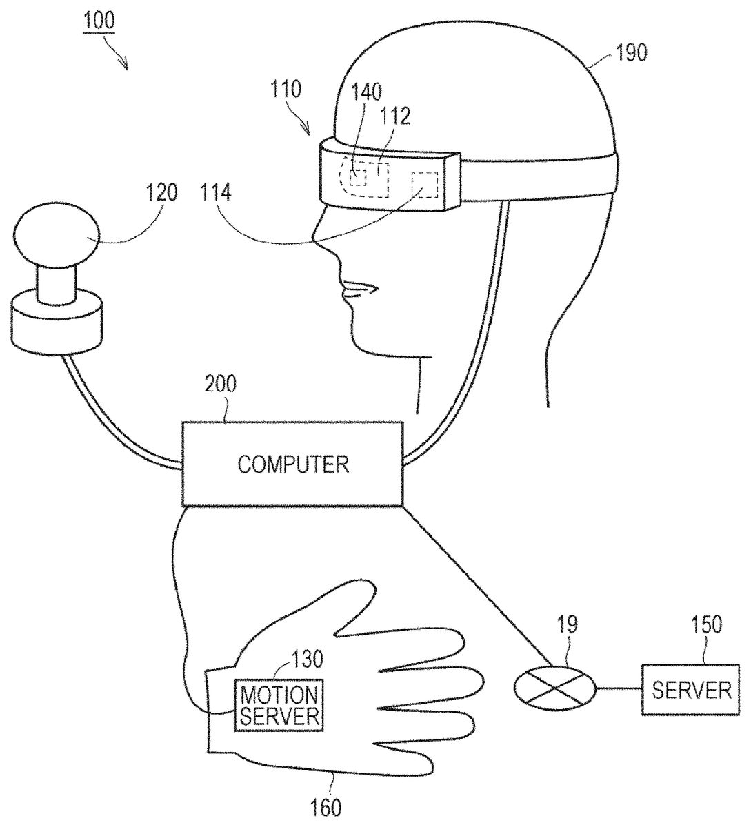
[Configuration of HMD System] With reference toFIG. 1, a configuration of a head mount display (HMD) system100is described.FIG. 1is a diagram of the configuration of the HMD system100according to at least one embodiment of this disclosure. In at least one aspect, the HMD system100is provided as a system for household use or a system for professional use.
InFIG. 1, the HMD system100according to at least one embodiment of this disclosure includes an HMD device110, an HMD sensor120, a controller160, and a computer200. The HMD device110includes a monitor112and an eye gaze sensor140. The controller160includes a motion sensor130. In at least one aspect, the computer200can be connected to a network19and can communicate to/from a server150connected to the network19. In at least one aspect, the HMD device110may include a sensor114instead of the HMD sensor120.
The HMD device110of at least one embodiment of this disclosure may be worn on a head of a user to provide a virtual space to the user during operation. More specifically, the HMD device110displays each of a right-eye image and a left-eye image on monitor112. When each eye of the user visually recognizes each image, the user may recognize the image as a three-dimensional image based on the parallax of both the eyes.
The monitor112is achieved as, for example, a non-transmissive display device or a partially transmissive display device. In at least one aspect, the monitor112is arranged on a main body of the HMD device110so as to be positioned in front of both the eyes of the user. Therefore, when the user visually recognizes the three-dimensional image displayed on the monitor112, the user can be immersed to the virtual space. According to at least one embodiment of this disclosure, the virtual space includes, for example, a background, objects that can be operated by the user, and menu images that can be selected by the user. According to at least one embodiment of this disclosure, the monitor112may be achieved as a liquid crystal monitor or an organic electroluminescence (EL) monitor included in a so-called smart phone or other information display terminals.
In at least one aspect, the monitor112may include a sub-monitor for displaying a right-eye image and a sub-monitor for displaying a left-eye image. In at least one aspect, the monitor112may be configured to integrally display the right-eye image and the left-eye image. In this case, the monitor112includes a high-speed shutter. The high-speed shutter operates so as to enable alternate display of the right-eye image and the left-eye image so that only one of the eyes can recognize the image at any single point in time.
The HMD sensor120includes a plurality of light sources (not shown). Each light source is achieved by, for example, an LED configured to emit an infrared ray. The HMD sensor120has a position tracking function for detecting the movement of the HMD device110. The HMD sensor120uses this function to detect the position and the inclination of the HMD device110in a real space.
In at least one aspect, the HMD sensor120may be achieved by a camera. In this case, the HMD sensor120may use image information of the HMD device110output from the camera to execute image analysis processing, to thereby enable detection of the position and the inclination of the HMD device110.
In at least one aspect, the HMD device110may include the sensor114instead of the HMD sensor120as a position detector. The HMD device110may use the sensor114to detect the position and the inclination of the HMD device110itself. For example, when the sensor114is an angular velocity sensor, a geomagnetic sensor, an acceleration sensor, or a gyrosensor, the HMD device110may use any of those sensors instead of the HMD sensor120to detect the position and the inclination of the HMD device110. As an example, when the sensor114is an angular velocity sensor, the angular velocity sensor detects over time the angular velocity about each of three axes of the HMD device110in the real space. The HMD device110calculates a temporal change of the angle about each of the three axes of the HMD device110based on each angular velocity, and further calculates an inclination of the HMD device110based on the temporal change of the angles.
In at least one aspect, the motion sensor130is mounted on the hand of the user to detect the movement of the hand of the user. For example, the motion sensor130detects a rotational speed and the number of rotations of the hand. The detection signal is transmitted to the computer200. The motion sensor130is provided to, for example, the glove-type controller160. According to at least one embodiment of this disclosure, to enhance safety in the real space, the controller160is mounted on an object that does not easily fly away, for example a glove-type object being worn on a hand of a user190. In at least one aspect, a sensor that is not mounted on the user190may detect the movement of the hand of the user190. For example, a signal of a camera that captures images of the user190may be input to the computer200as a signal representing the motion of the user190. The motion sensor130and the computer200are connected to each other through wired or wireless communication. In the case of wireless communication, the communication mode is not particularly limited, and for example, Bluetooth® or other known communication methods may be used.
The eye gaze sensor140is configured to detect a direction (line-of-sight direction) in which the lines of sight of the right eye and the left eye of the user190are directed. The direction is detected by, for example, a known eye tracking function. The eye gaze sensor140is achieved by a sensor having the eye tracking function. In at least one aspect, the eye gaze sensor140includes a right-eye sensor and a left-eye sensor. The eye gaze sensor140may be, for example, a sensor configured to irradiate the right eye and the left eye of the user190with infrared light, and to receive reflection light from the cornea and the iris with respect to the irradiation light, to thereby detect a rotational angle of each eyeball. The eye gaze sensor140can detect the line-of-sight direction of the user190based on each detected rotational angle.
The server150may transmit instructions to the computer200. In at least one aspect, the server150may communicate to/from another computer200for providing virtual reality to an HMD device used by another user. For example, when a plurality of users play a participatory game in an amusement facility, each computer200communicates to/from another computer200with a signal based on the motion of each user, to thereby enable the plurality of users to enjoy a common game in the same virtual space.
[Hardware Configuration]
With reference toFIG. 2, the computer200of at least one embodiment is described.FIG. 2is a block diagram of the hardware configuration of the computer200in at least one embodiment of this disclosure. The computer200includes a processor10, a memory11, a storage12, an input/output interface13, and a communication interface14. Each component is connected to a bus15.
The processor10is configured to execute a series of commands included in a program stored in the memory11or the storage12based on a signal transmitted to the computer200or on satisfaction of a condition determined in advance. In at least one aspect, the processor10is achieved as a central processing unit (CPU), a micro-processor unit (MPU), a field-programmable gate array (FPGA), or other devices.
The memory11temporarily stores programs and data. Temporary storage of data is performed in a non-transitory manner, such that detection of the stored date is possible. The programs are loaded from, for example, the storage12. The data includes data input to the computer200and data generated by the processor10. In at least one aspect, the memory11is achieved as a random access memory (RAM) or other volatile memories.
The storage12permanently stores programs and data. The storage12is achieved as, for example, a read-only memory (ROM), a hard disk device, a flash memory, or other non-volatile storage devices. The programs stored in the storage12include programs for providing a virtual space in the HMD system100, simulation programs, game programs, user authentication programs, and programs for achieving communication to/from other computers200. The data stored in the storage12includes data and objects for defining the virtual space.
In at least one aspect, the storage12may be achieved as a removable storage device like a memory card. In at least one aspect, a configuration that uses programs and data stored in an external storage device may be used instead of the storage12built into the computer200. With such a configuration, for example, in a situation where a plurality of HMD systems100are used as in an amusement facility, the programs and the data can be collectively updated.
The input/output interface13is configured to allow communication of signals among the HMD device110, the HMD sensor120, the motion sensor130, and the server150. In at least one aspect, the input/output interface13is achieved with use of a universal serial bus (USB) interface, a digital visual interface (DVI), a high-definition multimedia interface (HDMI)®, or other terminals. The input/output interface13is not limited to the examples described above.
The communication interface14is connected to the network19to communicate to/from other computers (for example, the server150) connected to the network19. In at least one aspect, the communication interface14is achieved as, for example, a local area network (LAN), other wired communication interfaces, wireless fidelity (WiFi), Bluetooth®, near field communication (NFC), or other wireless communication interfaces. The communication interface14is not limited to the examples described above.
In at least one aspect, the processor10loads one or more programs stored in the storage12to the memory11to execute a series of commands included in the program. The one or more programs may include an operating system of the computer200, an application program for providing a virtual space, and game software that can be executed in the virtual space with use of the controller160. The processor10transmits a signal for providing a virtual space to the HMD device110via the input/output interface13. The HMD device110displays a video on the monitor112based on the signal.
InFIG. 2, the computer200is provided outside of the HMD device110, but in at least one aspect, the computer200may be built into the HMD device110. As an example, a portable information communication terminal (for example, a smartphone) including the monitor112may function as the computer200.
Further, the computer200may be used in common among a plurality of HMD devices110. With such a configuration, for example, the same virtual space can be provided to a plurality of users, and hence each user can enjoy the same application with other users in the same virtual space.
According to at least one embodiment of this disclosure, in the HMD system100, a global coordinate system is set in advance. The global coordinate system has three reference directions (axes) that are respectively parallel to a vertical direction, a horizontal direction orthogonal to the vertical direction, and a front-rear direction orthogonal to both of the vertical direction and the horizontal direction in a real space. In at least one embodiment, the global coordinate system is one type of point-of-view coordinate system. Hence, the horizontal direction, the vertical direction (up-down direction), and the front-rear direction in the global coordinate system are defined as an x axis, a y axis, and a z axis, respectively. More specifically, the x axis of the global coordinate system is parallel to the horizontal direction of the real space, the y axis thereof is parallel to the vertical direction of the real space, and the z axis thereof is parallel to the front-rear direction of the real space.
In at least one aspect, the HMD sensor120includes an infrared sensor. When the infrared sensor detects the infrared ray emitted from each light source of the HMD device110, the infrared sensor detects the presence of the HMD device110. The HMD sensor120further detects the position and the inclination of the HMD device110in the real space in accordance with the movement of the user wearing the HMD device110based on the value of each point (each coordinate value in the global coordinate system). In more detail, the MID sensor120can detect the temporal change of the position and the inclination of the HMD device110with use of each value detected over time.
The global coordinate system is parallel to a coordinate system of the real space. Therefore, each inclination of the HMD device110detected by the HMD sensor120corresponds to each inclination about each of the three axes of the HMD device110in the global coordinate system. The HMD sensor120sets a UVW visual-field coordinate system to the MID device110based on the inclination of the HMD device110in the global coordinate system. The UVW visual-field coordinate system set to the HMD device110corresponds to a point-of-view coordinate system used when the user wearing the HMD device110views an object in the virtual space.
Overview of Configurations of Disclosed Embodiments
(Configuration 1) According to at least one embodiment of this disclosure, there is provided a method of providing a virtual space2to the HMD device110by the computer200. This method includes processing of defining the virtual space2by the processor10of the computer200. The method further includes processing of determining, by the processor10, a flying direction of an object that flies in the virtual space2in accordance with a motion of the user190of the HMD device110, based on the motion of the user190. The method further includes processing of causing, by the processor10, the MID device110to display a field of view of the user190in the virtual space2so that the field of view is moved in the flying direction.
(Configuration 2) According to at least one embodiment of this disclosure, in addition to Configuration 1, the processing of determining a flying direction includes processing of determining a flying distance of the object in the virtual space2based on the motion of the user190. The processing of causing the HMD device HO to display a field of view includes processing of causing the monitor112to display the field of view obtained from a position after movement in accordance with the flying distance in the virtual space2.
(Configuration 3) According to at least one embodiment of this disclosure, in addition to Configuration 1 or 2, the method further includes processing of moving, by the processor10, when the object reaches a target in the virtual space2, the user190in the virtual space2to the target.
(Configuration 4) According to at least one embodiment of this disclosure, in addition to Configuration 3, the processing of moving the user190to the target include moving, when the object reaches a stationary object, the user190to the stationary object in the virtual space2.
(Configuration 5) According to at least one embodiment of this disclosure, in addition to Configuration 3, the processing of moving the user190to the target include moving, when the object reaches a moving object, the user190in a traveling direction of the moving object.
(Configuration 6) According to at least one embodiment of this disclosure, in addition to any one of Configurations 3 to 5, the processing of moving the user190to the target include causing the HMD device110to display the field of view so that a landscape around the user190in the virtual space2approaches the user190.
(Configuration 7) According to at least one embodiment of this disclosure, in addition to Configuration 1 or 2, the method further include processing of causing, by the processor10, when the object reaches a target in the virtual space2, the HMD device110to display the field of view of the user190so that the target is attracted toward the user190.
(Configuration 8) According to at least one embodiment of this disclosure, in addition to any one of Configurations 1 to 7, the processing of determining a flying direction of an object include determining the flying direction of the object based on a physical quantity corresponding to a movement of a hand of the user190or on an operation performed on a controller connected to the computer200.
(Configuration 9) According to at least one embodiment of this disclosure, in addition to any one of Configurations 1 to 8, the processing of determining a flying distance of an object include determining the flying distance of the object based on a physical quantity corresponding to a movement of a hand of the user190or on an operation performed on a controller connected to the computer200.
(Configuration 10) The HMD system100according to at least one embodiment of this disclosure includes the HMD device110and the computer200configured to provide the virtual space2to the HMD device110. The computer200includes the memory configured to store a series of commands and the processor10configured to execute the series of commands. The processor10is configured to, when the processor10executes the series of commands, define the virtual space2. The processor10is further configured to, when the processor10executes the series of commands, determine the flying direction of the object that flies in the virtual space2in accordance with the motion of the user190of the HMD device110, based on the motion of the user190. The processor10is further configured to, when the processor10executes the series of commands, cause the HMD device110to display the field of view of the user190in the virtual space2so that the field of view is moved in the flying direction.
[UVW Visual-Field Coordinate System]
With reference toFIG. 3, the UVW visual-field coordinate system is described.FIG. 3is a schematic diagram of a UVW visual-field coordinate system to be set for the HMD device110of at least one embodiment of this disclosure. The HMD sensor120detects the position and the inclination of the HMD device110in the global coordinate system when the HMD device110is activated. The processor10sets the UVW visual-field coordinate system to the HMD device110based on the detected values.
InFIG. 3, the HMD device110sets a three-dimensional UVW visual-field coordinate system defining the head of the user wearing the HMD device110as a center (origin). More specifically, the HMD device110sets three directions newly obtained by inclining the horizontal direction, the vertical direction, and the front-rear direction (x axis, y axis, and z axis), which define the global coordinate system, about the respective axes by the inclinations about the respective axes of the HMD device110in the global coordinate system as a pitch direction (u axis), a yaw direction (v axis), and a roll direction (w axis) of the UVW visual-field coordinate system in the HMD device110.
In at least one aspect, when the user190wearing the HMD device110is standing upright and is visually recognizing the front side, the processor10sets the UVW visual field coordinate system that is parallel to the global coordinate system to the HMD device110. In this case, the horizontal direction (x axis), the vertical direction (y axis), and the front-rear direction (z axis) of the global coordinate system directly match with the pitch direction (u axis), the yaw direction (v axis), and the roll direction (w axis) of the UVW visual-field coordinate system in the HMD device110.
After the UVW visual-field coordinate system is set to the HMD device110, the HMD sensor120can detect the inclination (change amount of the inclination) of the HMD device110in the UVW visual-field coordinate system that is set based on the movement of the HMD device110. In this case, the HMD sensor120detects, as the inclination of the HMD device110, each of a pitch angle. (θu), a yaw angle (θv), and a roll angle (θw) of the HMD device110in the UVW visual-field coordinate system. The pitch angle (θu) represents an inclination angle of the HMD device110about the pitch direction in the UVW visual-field coordinate system. The yaw angle (θv) represents an inclination angle of the HMD device110about the yaw direction in the UVW visual-field coordinate system. The roll angle (θw) represents an inclination angle of the HMD device110about the roll direction in the UVW visual-field coordinate system.
The HMD sensor120sets, to the HMD device110, the UVW visual field coordinate system of the HMD device110obtained after the movement of the HMD device110based on the detected inclination angle of the HMD device110. The relationship between the HMD device110and the UVW visual-field coordinate system of the HMD device110is constant regardless of the position and the inclination of the HMD device110. When the position and the inclination of the HMD device110change, the position and the inclination of the UVW visual-field coordinate system of the HMD device110in the global coordinate system change in synchronization with the change of the position and the inclination.
In at least one aspect, the HMD sensor120may specify the position of the HMD device110in the real space as a position relative to the HMD sensor120based on the light intensity of the infrared ray or a relative positional relationship between a plurality of detection points (for example, a distance between the detection points), which is acquired based on output from the infrared sensor. Further, the processor10may determine the origin of the UVW visual-field coordinate system of the HMD device110in the real space (global coordinate system) based on the specified relative position.
[Virtual Space]
With reference toFIG. 4, the virtual space is further described.FIG. 4is a diagram of a mode of expressing the virtual space of at least one embodiment of this disclosure. The virtual space2has a structure with an entire celestial sphere shape covering a center21in all 360-degree directions. InFIG. 4, for the sake of simplicity, only the upper-half celestial sphere of the virtual space2is exemplified although one of ordinary skill would recognize that the virtual space2includes a lower-half celestial sphere as well. Each mesh section is defined in the virtual space2. The position of each mesh section is defined in advance as coordinate values in an XYZ coordinate system defined in the virtual space2. The computer200associates each partial image forming content (for example, still image or moving image) that can be developed in the virtual space2with each corresponding mesh section in the virtual space2, to thereby provide, to the user, the virtual space2in which a virtual space image22that can be visually recognized by the user is developed.
In at least one aspect, in the virtual space2, an XYZ spatial coordinate system having the center21as the origin is defined. The XYZ coordinate system is, for example, parallel to the global coordinate system. The XYZ coordinate system is one type of the point-of-view coordinate system, and hence the horizontal direction, the vertical direction (up-down direction), and the front-rear direction of the XYZ coordinate system are defined as an X axis, a Y axis, and a Z axis, respectively. Thus, the X axis (horizontal direction) of the XYZ coordinate system is parallel to the x axis of the global coordinate system, the Y axis (vertical direction) of the XYZ coordinate system is parallel to the y axis of the global coordinate system, and the Z axis (front-rear direction) of the XYZ coordinate system is parallel to the z axis of the global coordinate system.
When the HMD device110is activated, that is, when the HMD device110is initialized, a virtual camera1is arranged at the center21of the virtual space2. In synchronization with the movement of the HMD device110in the real space, the virtual camera1similarly moves in the virtual space2. With this, the change in position and direction of the HMD device110in the real space is reproduced similarly in the virtual space2.
The UVW visual-field coordinate system is defined in the virtual camera1similarly to the HMD device110. The Ii W visual field coordinate system of the virtual camera in the virtual space2is defined to be synchronized with the UVW visual-field coordinate system of the HMD device110in the real space (global coordinate system). Therefore, when the inclination of the HMD device110changes, the inclination of the virtual camera1also changes in synchronization therewith. The virtual camera1can also move in the virtual space2in synchronization with the movement of the user wearing the HMD device110in the real space.
The direction of the virtual camera1is determined based on the position and the inclination of the virtual camera1, and hence a line of sight (reference line of sight5) serving as a reference when the user visually recognizes the virtual space image22is determined based on the direction of the virtual camera1. The processor10of the computer200defines a field-of-view region23in the virtual space2based on the reference line of sight5. The field-of-view region23corresponds to a field of view of the user wearing the HMD device110in the virtual space2.
The line-of-sight direction of the user190detected by the eye gaze sensor140is a direction in the point-of-view coordinate system obtained when the user190visually recognizes an object. The UVW visual-field coordinate system of the HMD device110is equal to the point-of-view coordinate system used when the user190visually recognizes the monitor112. Further, the UVW visual-field coordinate system of the virtual camera1is synchronized with the UVW visual-field coordinate system of the HMD device110. Therefore, in the HMD system100in at least one aspect, the line-of-sight direction of the user190detected by the eye gaze sensor140can be regarded as the user's line-of-sight direction in the UVW visual-field coordinate system of the virtual camera1.
[User Line-of-Sight]
With reference toFIG. 5, determination of the user's line-of-sight direction is described.FIG. 5is a diagram of the head of the user wearing the HMD device of at least one embodiment of this disclosure.
In at least one aspect, the eye gaze sensor140detects lines of sight of the right eye and the left eye of the user190. In at least one aspect, when the user190is looking at a near place, the eye gaze sensor140detects lines of sight R1and L1. In at least one aspect, when the user190is looking at a far place, the eye gaze sensor140detects lines of sight R2and L2. In this case, the angles formed by the lines of sight R2and L2with respect to the roll direction w are smaller than the angles formed by the lines of sight R1and L1with respect to the roll direction w. The eye gaze sensor140transmits the detection results to the computer200.
When the computer200receives the detection values of the lines of sight R1and L1from the eye gaze sensor140as the detection results of the lines of sight, the computer200specifies a point of gaze N1being an intersection of both the lines of sight R1and L1based on the detection values. Meanwhile, when the computer200receives the detection values of the lines of sight R2and L2from the eye gaze sensor140, the computer200specifies an intersection of both the lines of sight R2and L2as the point of gaze. The computer200identifies a line-of-sight direction NO of the user190based on the specified point of gaze N1. The computer200detects, for example, an extension direction of a straight line that passes through the point of gaze N1and a midpoint of a straight line connecting a right eye R and a left eye L of the user190to each other as the line-of-sight direction N0. The line-of-sight direction NO is a direction in which the user190actually directs his or her lines of sight with both eyes. Further, the line-of-sight direction NO corresponds to a direction in which the user190actually directs his or her lines of sight with respect to the field-of-view region23.
In at least one aspect, the HMD system100may include microphones and speakers in any part constructing the HMD system100. When the user speaks to the microphone, an instruction can be given to the virtual space2with voice.
Further, in at least one aspect, the HMD system100may include a television broadcast reception tuner. With such a configuration, the HMD system100can display a television program in the virtual space2.
In at least one aspect, the HMD system100may include a communication circuit for connecting to the Internet or have a verbal communication function for connecting to a telephone line.
[Field-of-View Region]
With reference toFIG. 6andFIG. 7, the field-of-view region23is described.FIG. 6is a cross-sectional diagram of a YZ cross section obtained by viewing the field-of-view region23from an X direction in the virtual space2according to at least one embodiment of this disclosure.FIG. 7is a cross-sectional diagram of an XZ cross section obtained by viewing the field-of-view region23from a Y direction in the virtual space2according to at least one embodiment of this disclosure.
InFIG. 6, the field-of-view region23in the YZ cross section includes a region24. The region24is defined by the reference line of sight5of the virtual camera1and the YZ cross section of the virtual space2. The processor10defines a range of a polar angle α or more from the reference line of sight5serving as the center in the virtual space as the region24.
InFIG. 7, the field-of-view region23in the XZ cross section includes a region25. The region25is defined by the reference line of sight5and the XZ cross section of the virtual space2. The processor10defines a range of a polar angle β or more from the reference line of sight5serving as the center in the virtual space2as the region25.
In at least one aspect, the HMD system100causes the monitor112to display a field-of-view image26based on the signal from the computer200, to thereby provide the virtual space to the user190. The field-of-view image26corresponds to a part of the virtual space image22, which is superimposed on the field-of-view region23. When the user190moves the HMD device110worn on his or her head, the virtual camera1is also moved in synchronization with the movement. As a result, the position of the field-of-view region23in the virtual space2is changed. With this, the field-of-view image26displayed on the monitor112is updated to an image that is superimposed on the field-of-view region23of the virtual space image22in a direction in which the user faces in the virtual space2. The user can visually recognize a desired direction in the virtual space2.
In at least one embodiment, while the user190is wearing the HMD device110, the user190cannot visually recognize the real world but can visually recognize only the virtual space image22developed in the virtual space2. Therefore, the MID system100can provide a high sense of immersion in the virtual space2to the user.
In at least one aspect, the processor10may move the virtual camera1in the virtual space2in synchronization with the movement in the real space of the user190wearing the HMD device110. In this case, the processor10specifies an image region to be projected on the monitor112of the HMD device110(that is, the field-of-view region23in the virtual space2) based on the position and the direction of the virtual camera1in the virtual space2.
According to at least one embodiment of this disclosure, the virtual camera1is desired to include two virtual cameras, that is, a virtual camera for providing a right-eye image and a virtual camera for providing a left-eye image. Further, in at least one embodiment, an appropriate parallax be set for the two virtual cameras so that the user190can recognize the three-dimensional virtual space2. In at least one embodiment, a technical idea of this disclosure is exemplified assuming that the virtual camera1includes two virtual cameras, and the roll directions of the two virtual cameras are synthesized so that the generated roll direction (w) is adapted to the roll direction (w) of the HMD device110.
[Control Device of HMD Device]
With reference toFIG. 8, the control device of the HMD device110is described. According to at least one embodiment of this disclosure, the control device is achieved by the computer200having a known configuration.FIG. 8is a block diagram of the computer200of at least one embodiment of this disclosure as a module configuration.
InFIG. 8, the computer200includes a display control module220, a virtual space control module230, a memory module240, and a communication control module250. The display control module220includes, as sub-modules, a virtual camera control module221, a field-of-view region determining module222, a field-of-view image generating module223, and a reference line-of-sight specifying module224. The virtual space control module230includes, as sub-modules, a virtual space defining module231, a virtual object generating module232, and an object control module233. The memory module240stores space information241, object information242, and user information243.
According to at least one embodiment of this disclosure, the display control module220and the virtual space control module230are achieved by the processor10. According to at least one embodiment of this disclosure, a plurality of processors10may be combined to function as the display control module220and the virtual space control module230. The memory module240includes the memory11or the storage12. The communication control module250includes the communication interface14.
In at least one aspect, the display control module220is configured to control the image display on the monitor112of the HMD device110. The virtual camera control module221is configured to arrange the virtual camera1in the virtual space2, and control the behavior, the direction, and the like of the virtual camera1. The field-of-view region determining module222is configured to define the field-of-view region23. The field-of-view image generating module223is configured to generate the field-of-view image26to be displayed on the monitor112based on the determined field-of-view region23.
The reference line-of-sight specifying module224is configured to specify the line of sight of the user190based on the signal from the eye gaze sensor140.
The virtual space control module230is configured to control the virtual space2to be provided to the user190. The virtual space defining module231is configured to generate virtual space data representing the virtual space2to define the virtual space2in the HMD system100.
The virtual object generating module232is configured to generate a target to be displayed in the virtual space2. Examples of the target include forests, mountains, other landscapes, and animals to be displayed in accordance with the progression of the story of the game.
The object control module233is configured to control the motion of the object held by the user in the virtual space2. Examples of the object may include ropes, stones, lassos, and other throwing objects to be thrown in the virtual space2in synchronization with the motion of the user190in the real space.
The memory module240stores data to be used for providing the virtual space2to the user190by the computer200. In at least one aspect, the memory module240stores the space information241, the object information242, and the user information243. The space information241stores one or more templates defined for providing the virtual space2. The object information242stores content to be played in the virtual space2, and information for displaying an object to be used in the content. Examples of the content may include a game and content representing a landscape similar to that of the real society. The user information243stores a program for causing the computer200to function as the control device of the HMD system100, an application program that uses each piece of content stored in the object information242, and the like. The data and programs stored in the memory module240are input by the user of the HMD device110. Alternatively, the computer200downloads the data and programs from a computer (for example, the server150) that is managed by an external operator providing the content, to thereby store the data and programs in the memory module240.
The communication control module250may communicate to/from the server150or other information communication devices via the network19.
In at least one aspect, the display control module220and the virtual space control module230may be achieved with use of Unity® provided by Unity Technologies.
[Control Structure]
With reference toFIG. 9, the control structure of the HMD system100is described.FIG. 9is a flow chart of processing to be executed by the HMD system100according to at least one embodiment of this disclosure.
In Step S910, the processor10of the computer200serves as the virtual space defining module231to specify the virtual space image data.
In Step S920, the processor10initializes the virtual camera1. For example, the processor10arranges the virtual camera1at the center point defined in advance in the virtual space2, and directs the line of sight of the virtual camera1to a direction in which the user190faces.
In Step S930, the processor10serves as the field-of-view image generating module223to generate an initial field-of-view image. The generated field-of-view image is transmitted to the HMD device110by the communication control module250via the field-of-view image generating module223.
In Step S932, the monitor112of the HMD device110displays the field-of-view image based on the signal received from the computer200. The user190wearing the HMD device110may recognize the virtual space2through visual recognition of the field-of-view image.
In Step S934, the HMD sensor120detects the position and the inclination of the HMD device110based on a plurality of infrared beams emitted from the HMD device110. The detection result is transmitted to the computer200as movement detection data.
In Step S940, the processor10specifies the field-of-view direction of the user190wearing the HMD device110based on the position and the inclination of the HMD device110. The processor10executes an application program to display an object in the virtual space2based on the command included in the application program. The user190enjoys the content that can be visually recognized in the virtual space2through execution of the application program. In at least one aspect, examples of the content include ball games, lassos, other playgames, and guided tours in sightseeing spots.
In Step S942, the motion sensor130detects the movement of the hand of the user190. The signal representing the detected movement is transmitted to the computer200. The signal includes a rotational speed and an acceleration of the hand. For example, in at least one aspect, when an application program of a ball game is executed, there may be a scene in which a virtual user present in the virtual space2throws a ball in accordance with the swing of the arm of the user190. In this case, when the user190actually moves his or her arm, the rotational direction and the speed of the arm are detected. In at least one aspect, when a game of throwing a rope is executed and the user190rotates his or her arm, the rotational speed of the arm while the rope is rotated and the direction in which the arm is swung when the rope is thrown are detected. In at least one aspect, when a trip application program is executed, the virtual user in the virtual space2may function as a sightseeing guide. In this case, the movement of the right arm and the direction indicated by the right arm when the sightseeing guide in the virtual space2says “please look on the right side” to the tourist are detected.
In Step S950, the processor10specifies a flying direction based on the signal output from the motion sensor130. In at least one embodiment, the flying direction includes a direction in which balls, rings, stones, or other virtual objects fly in the virtual space2, or a direction indicated by an arm, a finger, a pointer, or other objects of the virtual user.
In Step S960, the processor10determines the field of view obtained after the movement of the virtual user based on the specified flying direction.
In Step S970, the processor10determines the direction of the virtual camera1based on the specified flying direction.
In Step S980, the processor10determines the field-of-view region based on the determined direction of the virtual camera1. In this embodiment, the field-of-view region represents a range that the virtual can visually recognize in the virtual space2.
In Step S990, the computer200generates the field-of-view image data for displaying the field-of-view image in accordance with the determined field-of-view region, and outputs the generated field-of-view image data to the MID device110.
In Step S992, the monitor112of the HMD device110updates the field-of-view image based on the received field-of-view image data, and displays the updated field-of-view image. The user190can recognize the updated field-of-view image, that is, the field of view obtained after the line of sight has been moved in the flying direction. While the above description refers to processor10, one of ordinary skill in the art would recognize that the functions of processor10could be separated among a plurality of processors.
With reference toFIG. 10, the control structure of the computer200is further described.FIG. 10is a flow chart of processing to be executed by the computer200when the virtual user throws a lasso or other objects to a target in the virtual space2according to at least one embodiment of this disclosure.
In Step S1010, the processor10serves as the virtual space defining module231to define the virtual space2in the memory11.
In Step S1020, the processor10detects the motion of the user190wearing the HMD device110based on the signal from the motion sensor130.
In Step S1030, the processor10determines the flying direction of the object that flies in the virtual space2based on the motion of the user190. For example, the processor10determines parameters such as an initial speed and the flying direction when the object flies based on the rotational speed and the throwing direction of the right hand of the user190. In at least one aspect, the processor10may determine the parameters based on the number of rotations and the throwing direction of the right hand of the user190. When the number of rotations is taken into consideration, as compared to the case where the rotational speed is taken into consideration, controller160can more easily perform control so that the object flies before the controller160separates from the hand of the user190, and hence the HMD device110can be used more safely.
In Step S1040, the processor10serves as the virtual object generating module232to generate the field-of-view image data for displaying the field-of-view image on the HMD device110so that the field of view of the user190in the virtual space2is moved in the flying direction. The processor10transmits the generated field-of-view image data to the HMD device110to cause the monitor112to display the field-of-view image based on the field-of-view image data.
In Step S1050, the processor10determines whether or not the object has reached the target of the virtual space2based on a virtual distance between the virtual user and the target in the virtual space and on the rotational motion of the arm of the user190. For example, the target may be a tree, a rock, or other stationary objects displayed in the virtual space2, or may be moving objects that run in the virtual space2such as an automobile, a dog, or a horse. Whether or not the object has reached the target may be determined based on, for example, the initial speed and the flying direction of the object in the virtual space2and the virtual distance from the virtual user to the target. This determination is applied in the virtual space2, and hence the air resistance or other physical quantities that need to be considered in the real space may be ignored. When the processor10determines that the object has reached the target of the virtual space2(YES in Step S1050), the control is switched to Step S1060. Otherwise (NO in Step S1050), the processor10returns the control to Step S1020.
In Step S1060, the processor10serves as the object control module233to move the position of the virtual user in the virtual space2to the target.
In at least one aspect, in the determination of Step S1050, for example, physical calculation to be executed in game software may be taken into consideration. In this case, for example, the size and the mass of the object, the gravity or the air resistance in the virtual space2, and the like may be taken into consideration. In this manner, a more enjoyable experience may be given in the virtual reality.
In at least one aspect, instead of the determination processing in Step S1050, the processor10may execute processing of specifying a target that the object has reached. Examples of the target include a tree, a rock, a ground, other stationary objects, an animal, a vehicle, and other moving objects. In at least one aspect, for example, the processor10may generate the field-of-view image so that the virtual user is moved to the target at high speed in the virtual space2. In this manner, even in a situation of high-speed movement, which is a unique situation in the virtual reality, the VR sickness can be reduced or prevented from occurring to the user190. While the above description refers to processor10, one of ordinary skill in the art would recognize that the functions of processor10could be separated among a plurality of processors.
[Movement of User with Respect to Stationary Object]
With reference toFIG. 11toFIG. 13, description is given of the movement of the user with respect to the stationary object in the virtual space2. According to at least one embodiment of this disclosure, a tree is exemplified as the stationary object, but the stationary object is not limited to the exemplified object. The stationary object may be at least an object that can be visually recognized by the user in the virtual space2, for example, a building or the other shore of a river.
FIGS. 11A and 11Bare diagrams of a state in which a mountain and a tree are present in the virtual space2according to at least one embodiment of this disclosure. The user recognizes a tree on the front right side and recognizes a mountain of the front left side.FIG. 11Ais an image1100that is visually recognized in the virtual space2by the user190wearing the HMD device110.FIG. 11Bis a diagram of a state in which the virtual space2is viewed from above (Y direction).
As an example, description is given on a scenario in which the HMD system100causes the virtual user to throw a rope in the virtual space2so that the virtual user is moved to a position at which the rope is caught. In at least one aspect, the user190wearing the HMD device110mounts a sensor on his or her right hand. The sensor detects the movement (rotation or throwing motion) of the right hand, and the detection result is input to the computer200. The computer200executes an application program for implementing the scenario, and transmits a signal for displaying the image to the monitor112. When the monitor112displays the image in accordance with the signal, the user190recognizes the image.
InFIG. 11A, in at least one aspect, the virtual user in the virtual space2visually recognizes a mountain and a tree1110. When the user190moves his or her hand on which the controller160is mounted in accordance with the progression of the above-mentioned scenario to perform a motion defined in advance in order to display a rope, a rope1120is displayed.
InFIG. 11B, when the virtual space2is viewed from the Y-axis direction, the rope1120is displayed in the visual field of the virtual camera1corresponding to the virtual user.
FIGS. 12A and 12Bare diagrams of a state when the virtual user throws the rope1120toward the tree1110according to at least one embodiment of this disclosure.FIG. 12Ais a diagram of a state in which the rope1120flies toward the tree1110.FIG. 12Bis a diagram of a state in which the virtual camera1is directed toward the tree1110in accordance with the thrown rope1120.
When the user190rotates his or her right arm several times and then swings his or her right hand to the front right side, the processor10switches the image to be displayed on the monitor112based on the signal output from the sensor mounted to the right hand. More specifically, the field-of-view image in the virtual space2is switched to an image having the tree1110at the center. When the virtual user throws the rope1120, the virtual user may visually recognize the field-of-view image as if the line of sight is switched in the direction of the tree1110. The user190can predict the direction in which the rope1120flies, and hence a so-called visually induced motion sickness (VR sickness) can be reduced or prevented without reducing the user's sense of immersion.
FIGS. 13A and 13Bare diagrams of the virtual user having moved to the vicinity of the tree1110in response to a loop of the rope1120being caught on the tree1110according to at least one embodiment of this disclosure.FIG. 13Ais a diagram of an image that is visually recognized by the virtual user that has moved to the vicinity of the tree1110.FIG. 13Bis a diagram of the position and the direction of the virtual camera1in the virtual space2.
InFIG. 13A, in at least one aspect, an image1300displays a state in which the virtual user has moved to the vicinity of the tree1110. When the user190performs such a motion of pulling the rope1120to himself or herself after the rope1120thrown by the virtual user present in the virtual space2is caught to a branch of the tree1110, the virtual user may move at high speed toward the tree1110in the virtual space2. More specifically, the virtual user may move at higher speed than the movement speed in accordance with the temporal change of the position of the HMD device110detected by the HMD sensor120. At this time, the field-of-view image may be displayed so that the landscape around the virtual user and the tree1110moves at high speed toward the virtual user.
InFIG. 13B, the position of the virtual camera1is instantaneously moved to the vicinity of the tree1110, and hence the user190may visually recognize the image as if the virtual user has instantaneously moved to the tree1110.
As described above, in at least one aspect, when the virtual user throws an object to the stationary object in the virtual space2based on the motion of the user190, the field-of-view image visually recognized by the virtual user is switched to a direction in which the object flies, that is, a direction in which the field of view of the virtual user moves. The motion of the user190includes the rotation of the arm and the gesture of throwing an object. The direction to switch the field-of-view image corresponds to such motions. Therefore, the user190can visually recognize the field-of-view image in the virtual space2in accordance with his or her motion, and hence the visually induced motion sickness may be suppressed or avoided.
[Movement of User with Respect to Stationary Object]
Next, with reference toFIG. 14toFIG. 16, description is given of the movement of the user with respect to a moving object in the virtual space2. According to at least one embodiment of this disclosure, a horse is exemplified as the moving object, but the moving object is not limited to the exemplified object. The moving object may be objects that move in the real space, such as other animals, automobiles, other vehicles, birds, airplanes, and rockets.
FIGS. 14A and 14Bare diagrams of a state in which a mountain is present in the virtual space2and a horse is running according to at least one embodiment of this disclosure.FIG. 14Ais a diagram of a field-of-view image1400that is visually recognized in the virtual space2by the user190wearing the HMD device110.FIG. 14Bis a diagram of a state in which the virtual space2is viewed from above (Y direction). In at least one aspect, the user190wearing the HMD device110visually recognizes the field-of-view image1400as the virtual user. The field-of-view image1400displays a mountain and a horse1410.
InFIG. 14A, when the user190performs a motion that is determined in advance, the processor10of the HMD device110displays a rope1120in the field-of-view image1400. When the user190moves his or her hand, the motion sensor130detects the movement of the hand, and the processor10displays, on the monitor112, such an image that the rope1120flies toward the running horse1410. At this time, the monitor112displays the image so that the horse1410is positioned at the center of the field-of-view image1400in accordance with the motion of the user190. Therefore, the direction in which the user190performs the motion and the direction displayed in the field-of-view image1400are substantially the same, and hence the VR sickness may be suppressed or avoided.
FIGS. 15A and 15Bare diagrams of an image1500displaying a state in which the target has moved in the virtual space2according to at least one embodiment of this disclosure.FIG. 15Ais a diagram of a state in which the horse1410has run and thus the location has changed in the virtual space2.FIG. 15Bis a diagram of a state in which the virtual space2is viewed from above (Y direction).
As illustrated inFIG. 15A, when the user190performs a motion of throwing the rope1120toward the running horse1410as the virtual user in the virtual space2, the motion sensor130detects the motion to detect the movement direction. For example, when the horse1410is running from the right to the left in the image1500, the user190performs a motion of swinging his or her right hand to the front left side. Then, the processor10generates a signal for switching the field-of-view image to the left direction, and transmits the signal to the monitor112.
InFIG. 15B, the direction of the virtual camera1corresponding to the virtual user is switched to the direction in which the horse1410is positioned at the center. When the monitor112displays the image under this state, the user190can visually recognize the horse1410at the center of the image in the virtual space2as the virtual user.
In at least one aspect, when the rope1120is caught to the horse1410, the user190performs a motion of pulling the rope1120, and thus the virtual user can be moved at high speed toward the horse1410.
FIGS. 16A and 16Bare diagrams of a state in which, in one aspect, the virtual user has moved to a moving object at high speed according to at least one embodiment of this disclosure. HG16A is a diagram of a field-of-view image1600to be visually recognized by the virtual user.FIG. 16Bis a diagram of a state in which the virtual space2is viewed from above (Y direction).
InFIG. 16A, the virtual user can move at high speed to the target in the virtual space2. For example, when the user190performs a motion of pulling the rope1120, for example, a motion of retreating his or her hand having the motion sensor130mounted thereon to himself or herself under a state in which the rope1120is caught to the horse1410as inFIG. 15A, the processor10displays, on the monitor11:2, such a screen that the virtual user approaches the horse1410at high speed. For example, such an image that the landscape around the virtual user passes behind the virtual user at high speed is displayed as the field-of-view image. In this manner, the user190that visually recognizes the field-of-view image can predict the movement direction that is based on his or her motion also in the virtual space2, and hence the VR sickness may be reduced or prevented from occurring.
As described above, according to at least one embodiment of this disclosure, the movement direction of the virtual user in the virtual space2is displayed based on the motion of the user190in the real space, and hence the motion of the user190and the movement direction in the virtual space2are synchronized with each other. As a result, even when the virtual user is moved in the virtual space2, the VR sickness may be reduced or prevented from occurring to the user190that has visually recognized the image at that time. The features disclosed above may be combined as appropriate.
[Configuration of HMD System]
With reference toFIG. 17, the configuration of the head mount display (HMD) system100A is described.FIG. 17is a diagram of an overview of the configuration of the HMD system100A according to at least one embodiment of this disclosure. In at least one aspect, the HMD system100A is provided as a system for household use or a system for professional use. Components having the same configurations as those of the above-mentioned HMD system100A are denoted by the same reference symbols, and redundant descriptions of the functions of those components are not repeated.
InFIG. 17, the HMD system100A according to at least one embodiment of this disclosure includes the above-mentioned HMD device110, the above-mentioned HMD sensor120, a board180, and a computer200A. The HMD device110includes the above-mentioned monitor112and the above-mentioned eye gaze sensor140. The board180includes an inclination sensor170. In at least one aspect, the computer200A can be connected to the network19, and can communicate to/from the server150connected to the network19. In at least one aspect, the HMD device110may include the above-mentioned sensor114instead of the HMD sensor120.
According to at least one embodiment of this disclosure, the HMD system100A may further include a controller160A. The controller160A may include a motion sensor130A.
The controller160A is configured to receive input of a command from the user190to the computer200A. In at least one aspect, the controller160A can be held by the user190. In at least one aspect, the controller160A can be mounted to the body or a part of the clothes of the user190. In at least one aspect, the controller160A may be configured to output at least one of a vibration, a sound, or light based on the signal transmitted from the computer200A.
In at least one aspect, the motion sensor130A is mounted on the hand of the user to detect the movement of the hand of the user. For example, the motion sensor130A detects the rotational speed and the number of rotations of the hand. The detection signal is transmitted to the computer200A. The motion sensor130A is provided to, for example, the glove-type controller160A. According to at least one embodiment of this disclosure, for the safety in the real space, the controller160A is desired to be mounted on an object that does not easily fly away like a glove-type object being worn on the hand of the user190. In at least one aspect, a sensor that is not mounted on the user190may detect the movement of the hand of the user190. For example, a signal of a camera that photographs the user190may be input to the computer200A as a signal representing the motion of the user190. The motion sensor130A and the computer200A are connected to each other through wired or wireless communication. In the case of wireless communication, the communication mode is not particularly limited, and for example, Bluetooth® or other known communication methods may be used.
The inclination sensor170is achieved by, for example, an acceleration sensor or a touch sensor. According to at least one embodiment of this disclosure, in a case of a member having a spherical bottom portion as the board180, an acceleration sensor is used as the inclination sensor170. According to at least one embodiment of this disclosure, when the user190uses equipment having side walls like a bobsled, a touch sensor may be arranged on each of the right and left side walls as the inclination sensor in addition to the acceleration sensor or instead of the acceleration sensor. In this case, the equipment may be detected to be inclined toward the side wall touched by the user190.
The board180is configured to incline in accordance with a load applied to its upper surface. For example, in at least one aspect, the board180has a bottom surface that is formed to have an arc-shaped inclination. In at least one aspect, the board180includes a plurality of springs or other elastic members arranged so as to transmit the applied load to the floor on which the board180is placed.
[Hardware Configuration]
With reference toFIG. 18, the computer200A of this embodiment is described.FIG. 18is a block diagram of an example of the hardware configuration of the computer200A according to at least one embodiment of this disclosure. The computer200A includes the above-mentioned processor10, the above-mentioned memory11, the above-mentioned storage12, the above-mentioned input/output interface13, and the above-mentioned communication interface14. Each component is connected to the above-mentioned bus15.
According to at least one embodiment of this disclosure, the input/output interface13is configured to allow communication of signals among the HMD device110, the HMD sensor120, the motion sensor130A, and the inclination sensor170. In at least one aspect, the input/output interface13is achieved with use of a universal serial bus (USB) interface, a digital visual interface (DVI), a high-definition multimedia interface (HDMI) (trademark), or other terminals. The input/output interface13is not limited to ones described above.
According to at least one embodiment of this disclosure, the input/output interface13may further communicate to/from the controller160A. For example, the input/output interface13receives input of a signal output from the motion sensor130A. In at least one aspect, the input/output interface13transmits a command output from the processor10to the controller160A. The command instructs the controller160A to vibrate, output a sound, emit light, or the like. When the controller160A receives the command, the controller160A executes any one of vibration, sound output, and light emission in accordance with the command.
In at least one aspect, the processor10loads one or more programs stored in the storage12to the memory11to execute a series of commands included in the program. The one or more programs may include an operating system of the computer200A, an application program for providing a virtual space, and game software that can be executed in the virtual space with use of the controller160A. The processor10transmits a signal for providing a virtual space to the HMD device110via the input/output interface13. The HMD device110displays a video on the monitor112based on the signal.
According to at least one embodiment of this disclosure, there is provided a method of providing a virtual space to a head mounted display device by a computer. This method includes defining the virtual space by at least one processor. The method further includes detecting, by the at least one processor, a direction in which a user of the head mounted display device is inclined (for example, one of right-left direction and front-back direction). The method further includes determining, by the at least one, processor, a movement direction of a virtual user corresponding to the user190in the virtual space based on the direction in which the user190is inclined. The method further includes causing, by the at least one processor, the head mounted display device to display a field of view of the virtual user in the virtual space so that the field of view is moved in the determined movement direction of the virtual user.
According to at least one embodiment of this disclosure, the step of determining a movement direction includes determining the movement direction in accordance with a time for which the inclination of the user190is continued.
According to at least one embodiment of this disclosure, the step of determining a movement direction includes determining the movement direction in accordance with a degree of the inclination of the user190.
According to at least one embodiment of this disclosure, the method further includes a step of determining, by the at least one processor, a movement distance of the virtual user in the virtual space based on the detected inclination of the user190. The step of causing the head mounted display device to display a field of view includes causing the head mounted display device to display the field of view of the virtual user so that the field of view is moved by the movement distance in the movement direction.
According to at least one embodiment of this disclosure, a method of providing a virtual space to a head mounted display device by a computer is disclosed. The method includes defining a virtual space by at least one processor. The method further includes detecting, by the at least one processor, a direction in which a user of the head mounted display device is inclined. The method further includes determining, by the at least one processor, a movement distance of a virtual user in the virtual space based on the detected inclination of the user190. The method further includes causing, by the at least one processor, the head mounted display device to display a field of view of the virtual user in the virtual space so that the field of view is moved by the determined movement distance of the virtual user.
According to at least one embodiment of this disclosure, the step of determining a movement distance includes determining the movement distance in accordance with a time for which the inclination of the user190is continued.
According to at least one embodiment of this disclosure, the step of determining a movement distance includes determining the movement distance in accordance with a degree of the inclination of the user190.
According to at least one embodiment of this disclosure, the step of detecting a direction in which the user190is inclined includes a step of detecting an acceleration based on a posture or a motion performed by the user190through weight shift.
According to at least one embodiment of this disclosure, the step of detecting a direction in which the user190is inclined includes detecting a load applied from the user190.
According to at least one embodiment of this disclosure, the processor is configured to define a virtual space, detect a direction in which a user of the head mounted display device is inclined, determine a movement direction of a virtual user in the virtual space based on the detected direction, and cause the head mounted display device to display a field of view of the virtual user in the virtual space so that the field of view is moved in the determined movement direction of the virtual user.
According to at least one embodiment of this disclosure, the processor is further configured to determine a movement distance of the virtual user in the virtual space based on the detected inclination of the user190. Causing the head mounted display device to display a field of view includes causing the head mounted display device to display the field of view of the virtual user so that the field of view is moved by the movement distance in the movement direction.
According to at least one embodiment of this disclosure, the processor is configured to define a virtual space, detect a direction in which a user of the head mounted display device is inclined, determine a movement distance of a virtual user in the virtual space based on the detected direction, and cause the head mounted display device to display a field of view of the virtual user in the virtual space so that the field of view is moved by the determined movement distance of the virtual user.
[Control Device of HMD Device]
With reference toFIG. 19, the control device of the HMD device110is described. According to at least one embodiment of this disclosure, the control device is achieved by the computer200A having a known configuration.FIG. 19is a block diagram of the computer200A of one embodiment of this disclosure as a module configuration according to at least one embodiment of this disclosure.
InFIG. 19, the computer200A includes the above-mentioned display control module220, the above-mentioned virtual space control module230, the above-mentioned memory module240, and the above-mentioned communication control module250. The display control module220includes, as sub-modules, the above-mentioned virtual camera control module221, the above-mentioned field-of-view region determining module222, the above-mentioned field-of-view image generating module223, and the above-mentioned reference line-of-sight specifying module224. The virtual space control module230includes, as sub-modules, the above-mentioned virtual space defining module231, the above-mentioned virtual object generating module232, the above-mentioned object control module233, a movement direction determining module234, and a movement distance determining module235.
The movement direction determining module234is configured to determine the movement direction of the virtual user in the virtual space2based on the output from the inclination sensor170. According to at least one embodiment of this disclosure, the movement direction determining module234is configured to detect the direction in which a load is applied by the user190based on the signal output from the inclination sensor170, to thereby determine the direction as a direction to move the virtual user.
The movement distance determining module235is configured to determine the movement distance of the virtual user based on the output from the inclination sensor170. For example, when the board180in a horizontal state is inclined, the movement distance determining module235determines the movement distance in accordance with an inclination angle. In at least one aspect, the movement distance determining module235is configured to determine the movement distance of the virtual user based on a virtual movement distance per degree of inclination angle defined in advance in the program executed by the processor10, and on the inclination angle. According to at least one embodiment of this disclosure, the movement distance determining module235is configured to determine the movement distance of the virtual user based on the time for which the inclination is continued. For example, the movement distance determining module235may determine the movement distance of the virtual user based on a product of the virtual movement distance per time defined in advance in the program executed by the processor10and the time for which the inclination is continued.
[Control Structure]
With reference toFIG. 20, the control structure of the HMD system100A is described.FIG. 20is a flow chart of processing to be executed by the HMD system100A according to at least one embodiment of this disclosure. InFIG. 20, the processing other than Step S942A is similar to the processing described above, and hence redundant description is not repeated.
In Step S940, the processor10specifies the field-of-view direction of the user190wearing the HMD device110based on the position and the inclination of the HMD device110. The processor10executes an application program to display an object in the virtual space2based on the command included in the application program. The user190enjoys the content that can be visually recognized in the virtual space2through execution of the application program. In at least one aspect, examples of the content include bobsled, other sports using sleds, skiing, and snowboarding. According to at least one embodiment of this disclosure, the user190may sit on the board180and change his or her posture in accordance with the transition of the image displayed on the monitor112.
In Step S942A, the inclination sensor170detects the direction in which the user190is inclined. The signal representing the detected inclination is transmitted to the computer200A. The signal includes an inclination angle of the board180. For example, in at least one aspect, when an application program of a downhill race like bobsled is executed, there may be a scene in which the virtual user present in the virtual space2controls the traveling direction of the bobsled displayed in the virtual space2in accordance with the inclination of the user190. In this case, when the user190inclines his or her body, the inclination sensor170detects the direction of the inclination.
In Step S950, the processor10determines the movement direction and the movement distance of the virtual user based on the signal output from the inclination sensor170. In at least one embodiment, the movement direction includes a direction in which the virtual user or a sled or other types of equipment on which the virtual user is sitting travels in the virtual space2. In at least one aspect, when only the movement direction is required, the processor10may serve as the movement direction determining module234to determine only the movement direction. In at least one aspect, when only the movement distance is required, the processor10may serve as the movement distance determining module235to determine only the movement distance.
In at least one aspect, the processor10may be configured to determine the movement direction and a movement speed of the virtual user based on the signal output from the inclination sensor170. The movement speed of the virtual user may be set to be increased as the inclination angle of the board180is increased.
In Step S960, the processor10determines the field of view obtained after the movement of the virtual user based on the determined movement direction and movement distance.
In Step S970, the processor10determines the position and the direction of the virtual camera1in the virtual space2based on the determined movement direction and movement distance.
In Step S980, the processor10determines the field-of-view region based on the determined position and direction of the virtual camera1. In at least one embodiment, the field-of-view region represents a range that the virtual user can visually recognize in the virtual space2.
In Step S990, the computer200A generates the field-of-view image data for displaying the field-of-view image in accordance with the determined field-of-view region, and outputs the generated field-of-view image data to the HMD device110. The field-of-view image data is configured to enable display of a mode in which a landscape around the virtual user approaches the virtual user at high speed so that the virtual user moves at high speed in the determined movement direction.
In Step S992, the monitor112of the HMD device110updates the field-of-view image based on the received field-of-view image data, and displays the updated field-of-view image. The user190can recognize the updated field-of-view image, that is, the field of view obtained after the line of sight has been moved in the movement direction. While the above description refers to processor10, one of ordinary skill in the art would recognize that the functions of processor10could be separated among a plurality of processors.
With reference toFIG. 21, the control structure of the computer200A is further described.FIG. 21is a flow chart of the processing to be executed by the computer200A in accordance with the motion of the user190sitting on the board180according to at least one embodiment of this disclosure.
In Step S1010A, the processor10serves as the virtual space defining module231to define the virtual space2in the memory11.
In Step S1020A, the processor10detects the direction in which the user190wearing the HMD device110and sitting on the board180is inclined, specifically, the right, left, front, or back direction based on the signal from the inclination sensor170.
In Step S1030A, the processor10determines the movement direction of the virtual user traveling in the virtual space2based on the inclination of the user190. For example, when the user190inclines his or her body to the right side for a certain time period, the processor10determines that the virtual user or a vehicle on which the virtual user is sitting is moved to the right side. In at least one aspect, the processor10determines the direction in which the virtual user is moved to the right side in accordance with the number of times that the user190performs the motion of temporarily inclining his or her body. For example, when the user190performs a motion of inclining his or her body once within a time period defined in advance, the processor10determines that the virtual user is moved by one degree to the right side with respect to the traveling direction. When the user190performs the motion 10 times, the processor10determines that the virtual user is moved by 10 degrees to the right side.
In at least one aspect, also when the user190performs a motion of inclining his or her body to the left side, similarly to the case where the motion of inclining the body to the right side is performed, the processor10determines the left movement direction.
According to at least one embodiment of this disclosure, the inclination sensor170may detect that the user190has inclined his or her body forward. At this time, the processor10may detect that the user190has inclined his or her body forward in accordance with the signal from the inclination sensor170, and may determine the movement distance based on the inclination angle. For example, in a case where the program executed by the processor10predetermines to move the virtual user by 10 meters when the forward inclination of one degree is detected, when the processor10detects that the user190has inclined forward by 5 degrees, the processor10determines to move the virtual user by 50 meters in the virtual space2.
In Step S1040A, the processor10serves as the virtual object generating module232to generate the field-of-view image data for displaying the field-of-view image on the HMD device110so that the field of view of the virtual user in the virtual space2is moved in the movement direction determined in Step S1030A. According to at least one embodiment of this disclosure, the processor10generates the field-of-view image data in which, in addition to the movement direction, the movement distance obtained based on the time for which the inclination of the user190is continued is reflected. The processor10transmits the generated field-of-view image data to the HMD device110, and the HMD device110displays the field-of-view image on the monitor112based on the field-of-view image data. While the above description refers to processor10, one of ordinary skill in the art would recognize that the functions of processor10could be separated among a plurality of processors.
[Movement of Sitting User]
With reference toFIG. 22AtoFIG. 24C, one mode of detecting the inclination of the user190is described.
FIGS. 22A, 22B and 22Care diagrams of a mode in which the user190is sitting on the board180of at least one embodiment of this disclosure.FIG. 22Ais a diagram of a mode in which the user190wearing the HMD device110(not shown) is sitting on the board180while maintaining the horizontal state.FIG. 22Bis a diagram of a mode in which the user190shifts his or her weight to incline the board180to the left side as viewed from the user190.FIG. 22Cis a diagram of a state in which the user shifts his or her weight to incline the board180to the right side as viewed from the user190. When the board180is inclined, the inclination sensor170outputs a signal corresponding to the direction. The output signal is input to the computer200A. The direction in which the inclination is detected is not limited to the left as inFIG. 22Bor to the right as inFIG. 22C. According to at least one embodiment of this disclosure, the inclination sensor170may detect the forward inclination when the user190shifts his or her weight forward or the backward inclination when the user190shifts his or her weight backward.
FIGS. 23A, 23B and 23Care diagrams of a mode in which the user190is standing on the board180of at least one embodiment of this disclosure.FIG. 23Ais a diagram of a mode in which the user190wearing the HMD device110(not shown) is sitting on the board180while maintaining the horizontal state.FIG. 23Bis a diagram of a mode in which the user190shifts his or her weight to incline the board180to the left side as viewed from the user190.FIG. 23Cis a diagram of a state in which the user shifts his or her weight to incline the board180to the right side as viewed from the user190. When the board180is inclined, the inclination sensor170outputs a signal corresponding to the direction. The output signal is input to the computer200A. The direction in which the inclination is detected is not limited to the left as inFIG. 23Bor to the right as inFIG. 23C. According to at least one embodiment of this disclosure, the inclination sensor170may detect the forward inclination when the user190shifts his or her weight forward or the backward inclination when the user190shifts his or her weight backward. The user190can predict the movement direction of the virtual user in the virtual space2in accordance with his or her weight shift, and hence a so-called visually induced motion sickness (VR sickness) can be reduced or prevented without reducing the user's sense of immersion.
With reference toFIGS. 24A, 24B and 24C, another mode of detection of the inclination is described.FIGS. 24A, 24B and 24Care diagrams of a mode in which the user190is sitting on a sled1300A in at least one embodiment of this disclosure. On both side surfaces of the sled1300A, touch sensors1370and1371are arranged. The output of the touch sensors1370and1371is connected to an input interface of the computer200A. In at least one aspect, one or more sleds1300A may be provided in a playground.
FIG. 24Ais a diagram of a mode in which the user190wearing the HMD device110(not shown) is sitting on the sled1300A while maintaining the horizontal state. At this time, the user190is not touching the touch sensor1370or1371.
FIG. 24Bis a diagram of a mode in which the user190shifts his or her weight to incline the sled1300A to the right side as viewed from the user190. When the sled1300A is inclined to the right side and thus the right hand of the user touches the touch sensor1370, a signal output from the touch sensor1370is input to the computer200A. The processor10detects that the sled1300A has inclined to the right side based on the signal. Further, the processor10generates the field-of-view image data so that the field of view from the front right side of the virtual user in the virtual space2may be recognized by the user190. The processor10transmits the field-of-view image data to the HMD device110, and the HMD device110displays the image based on the field-of-view image data on the monitor112. When the user190views the image, the user190feels like the user is moving in the right direction in the virtual space2.
FIG. 24Cis a diagram of a state in which the user190shifts his or her weight to incline the sled1300A to the left side as viewed from the user190. When the sled1300A is inclined to the left side and thus the left hand of the user touches the touch sensor1371, a signal output from the touch sensor1371is input to the computer200A. The processor10detects that the sled1300A has inclined to the left side based on the signal. Further, the processor10generates the field-of-view image data so that the field of view from the front left side of the virtual user in the virtual space2may be recognized by the user190. The processor10transmits the field-of-view image data to the HMD device110to display the image based on the field-of-view image data on the monitor112. When the user190views the image, the user190feels like the user is moving in the left direction in the virtual space2.
Also in the example illustrated inFIGS. 24A-C, similarly toFIGS. 22A-CorFIGS. 23A-C, the inclination sensor170may be arranged on the bottom portion of the sled1300A instead of the touch sensors1370and1371.
Next, with reference toFIG. 25AtoFIG. 27B, the movement of the virtual user in the virtual space2is described. According to at least one embodiment of this disclosure, the user190wearing the HMD device110visually recognizes a field-of-view image1400A in the virtual space2as the virtual user.
FIGS. 25A and 25Bare diagrams of a case where the board180or the sled1300A on which the user190is sitting or standing is maintained in a horizontal state according to at least one embodiment of this disclosure. At this time, the processor10determines that the user190is maintaining the horizontal state based on the signal output from the inclination sensor170or the touch sensors1370and1371. Further, the processor10generates such field-of-view image data that the image in the horizontal state is visually recognized in the virtual space2, and transmits the field-of-view image data to the monitor112of the HMD device110.
As inFIG. 25A, when the monitor11:2displays an image based on the field-of-view image data, the user190recognizes the field-of-view image1400A as the virtual user. At this time, as inFIG. 25B, the virtual camera1corresponding to the virtual user captures the field-of-view region23corresponding to the field of view of the virtual user.
[Movement to Right Side]
FIGS. 26A and 26Bare diagrams of a case where the user190maintaining a horizontal state leans to the right side to incline the board180or the sled1300A to the right side according to at least one embodiment of this disclosure. At this time, the processor10determines that the user190is inclined to the right side based on the signal output from the inclination sensor170or the touch sensors1370and1371. Further, the processor10generates the field-of-view image data in which the virtual user in the virtual space2is recognized as having moved to the right side from the original location (for example, seeFIGS. 25A and 25B). For example, the processor10generates the field-of-view image data for displaying the field-of-view image so that the image that is recognized in the virtual space2flows from the right to the left, and transmits the field-of-view image data to the HMD device110.
As inFIG. 26A, the monitor112displays a field-of-view image1500A based on the field-of-view image data. A tree1410A displayed on the right in the field-of-view image1400A is moved to the center of the field-of-view image1500A.
As inFIG. 26B, such movement corresponds to, for example, movement of the virtual camera1assumed in the virtual space2to the front of the tree1410A. The processor10generates the field-of-view image data in order to display an image similar to the image recognized in accordance with the movement of the virtual camera1.
The transition from the field-of-view image1400A to the field-of-view image1500A is performed based on the shift of the weight of the user190to the right side. In this manner, the user190can recognize the movement in the virtual space2due to the transition of the field-of-view image in accordance with his or her motion corresponding to the weight shift to the right side, and hence the inclination of the user190and the movement direction in the virtual space2are synchronized with each other. As a result, occurrence of a so-called VR sickness may be suppressed or avoided.
[Movement to Left Side]
FIGS. 27A and 27Bare diagrams of a case where the user190maintaining the horizontal state leans to the left side to incline the board180or the sled1300A to the left side according to at least one embodiment of this disclosure. At this time, the processor10determines that the user190is inclined to the left side based on the signal output from the inclination sensor170or the touch sensors1370and1371. Further, the processor10generates the field-of-view image data in which the virtual user in the virtual space2is recognized as having moved to the left side from the original location (for example, seeFIGS. 25aand25B). For example, the processor10generates the field-of-view image data for displaying the field-of-view image so that the image that is recognized in the virtual space2flows from the left to the right, and transmits the field-of-view image data to the HMD device110.
As inFIG. 27A, the monitor112displays a field-of-view image1600A based on the field-of-view image data. A mountain1420A that has been displayed on the left in the field-of-view image1400A is moved to the center of the field-of-view image1600A.
As inFIG. 27B, such movement corresponds to, for example, movement of the virtual camera1assumed in the virtual space2to the front of the mountain1420A. The processor10generates the field-of-view image data in order to display an image similar to the image recognized in accordance with the movement of the virtual camera1.
The transition from the field-of-view image1400A to the field-of-view image1600A is performed based on the shift of the weight of the user190to the left side. In this manner, the user190can recognize the movement in the virtual space2due to the transition of the field-of-view image in accordance with his or her motion corresponding to the weight shift to the left side, and hence the inclination of the user190and the movement direction in the virtual space2are synchronized with each other. As a result, occurrence of a so-called VR sickness may be suppressed or avoided.
[Movement to Forward Side]
FIGS. 28Aand B are diagrams of a case where the user190maintaining the horizontal state leans forward to incline the board180forward according to at least one embodiment of this disclosure. The processor10determines that the user190is inclined to the forward side based on the signal output from the inclination sensor170. Further, the processor10generates the field-of-view image data in which the virtual user in the virtual space2is recognized as having moved to the forward side from the original location (for example, seeFIGS. 25A and 25B). For example, the processor10generates the field-of-view image data for displaying the field-of-view image so that the image that is recognized in the virtual space2is approaching at high speed, and transmits the field-of-view image data to the HMD device110.
As inFIG. 28A, the monitor112displays a field-of-view image1700based on the field-of-view image data. The tree1410A and the mountain1420A that have been displayed small at far places in the field-of-view image1400A are displayed large in accordance with the movement distance in the virtual space2. In at least one aspect, the movement distance in the virtual space2may be calculated based on, for example, the angle of the forward inclination of the user190and on the movement distance per unit angle determined in advance. In at least one aspect, the movement distance may be calculated based on the time for which the state of the forward inclination is continued and on the movement distance per unit time determined in advance.
As inFIG. 28B, the movement of the field-of-view image in the virtual space2corresponds to, for example, movement of the virtual camera1assumed in the virtual space2at high speed toward the tree1410A or the mountain1420A. The processor10generates the field-of-view image data in order to display an image similar to the image recognized in accordance with the movement of the virtual camera1.
The transition from the field-of-view image1400A to the field-of-view image1700is performed based on the shift of the weight of the user190to the front side. The user190can recognize the movement in the virtual space2in accordance with his or her motion corresponding to the weight shift, and hence the inclination of the user190and the movement direction in the virtual space2are synchronized with each other. As a result, occurrence of a so-called VR sickness may be suppressed or avoided.
[Movement to Backward Side]
FIGS. 29A and 29Bare diagrams of a case where the user190maintaining the horizontal state leans backward to incline the board180backward according to at least one embodiment of this disclosure. The processor10determines that the user190is inclined to the backward side based on the signal output from the inclination sensor170. Further, the processor10generates the field-of-view image data in which the virtual user in the virtual space2is recognized as having moved to the backward side from the original location (for example, seeFIGS. 25aand25B). For example, the processor10generates the field-of-view image data for displaying the field-of-view image so that the image that is recognized in the virtual space2is moving away, and transmits the field-of-view image data to the HMD device110.
As inFIG. 29A, the monitor112displays a field-of-view image1800based on the field-of-view image data. The tree1410A and the mountain1420A that have been displayed in the field-of-view image1400A are displayed smaller as compared to the case illustrated inFIGS. 25A and 25B. For example, the tree1410A and the mountain1420A are displayed smaller in accordance with the movement distance in the virtual space2. In at least one aspect, the movement distance in the virtual space2may be calculated based on, for example, the angle of the backward inclination the user190and on the movement distance per unit angle determined in advance. In at least one aspect, the movement distance may be calculated based on the time for which the state of the backward inclination is continued and on the movement distance per unit time determined in advance.
As inFIG. 29B, the movement of the field-of-view image in the virtual space2corresponds to, for example, movement of the virtual camera1assumed in the virtual space2at high speed in a direction departing from the tree1410A or the mountain1420A. The processor10generates the field-of-view image data in order to display an image similar to the image recognized in accordance with the movement of the virtual camera1.
The transition from the field-of-view image1400A to the field-of-view image1800is performed based on the shift of the weight of the user190to the back side. The user190can recognize the movement in the virtual space2in accordance with his or her motion corresponding to the weight shift, and hence the inclination of the user190and the movement direction in the virtual space2are synchronized with each other similarly to the case of the forward inclination. As a result, occurrence of a so-called VR sickness may be suppressed or avoided.
As described above, according to at least one embodiment of this disclosure, the movement direction of the virtual user in the virtual space2is determined based on the direction in which the user190is inclined in the real space, and hence the inclination of the user190and the movement direction in the virtual space2are synchronized with each other. As a result, even when the virtual user is moved in the virtual space2, the VR sickness may be reduced or prevented from occurring to the user190that visually recognizes the image at this time. The features described in the embodiments above may be combined as appropriate. For example, regarding the forward or backward component when the user190maintaining the horizontal direction inclines the board180, the movement distance may be calculated so that the virtual user moves forward or backward in the direction of the reference line of sight5of the virtual camera1in the virtual space2, and the virtual camera1may be rotated about the yaw direction (v axis) in accordance with the degree of inclination in which the user inclines the board180to the right side or the left side.
It is to be understood that the embodiments disclosed above are merely examples in all aspects and in no way intended to limit this disclosure. The scope of this disclosure is defined by the appended claims and not by the description made above, and all the modifications made within the scope and spirit equivalent to those of the appended claims are included in this disclosure.
The following contents are supplementary notes for this disclosure.
(Item 1)
A method of providing a virtual space to a head mounted display device by a computer. The method includes defining a virtual space. The method further includes detecting a direction in which a user of the head mounted display device is inclined. The method further includes determining a movement direction of the user in the virtual space based on the detected direction in which the user is inclined. The method further includes causing the head mounted display device to display a field of view of the user in the virtual space so that the field of view is moved in the determined movement direction of the user.
(Item 2)
A method according to Item 1, in which the determining of the movement direction includes determining the movement direction in accordance with a time for which inclination of the user is continued.
(Item 3)
A method according to Item 1, in which the determining of the movement direction includes determining the movement direction in accordance with the direction which the user is inclined.
(Item 4)
A method according to any one of items 1 to 3, further including determining a movement distance of the user in the virtual space based on detected inclination of the user. The causing of the head mounted display device to display a field of view includes causing the head mounted display device to display the field of view of the user so that the field of view is moved by the movement distance in the movement direction.
(Item 5)
A method of providing a virtual space to a head mounted display device by a computer. The method includes defining a virtual space. The method further includes detecting inclination of a user of the head mounted display device is inclined. The method further includes determining a movement distance of the user in the virtual space based on the detected inclination of the user. The method further includes causing the head mounted display device to display a field of view of the user in the virtual space so that the field of view is moved in the determined movement distance of the user.
(Item 6)
A method according to Item 4 or 5, in which the determining of the movement distance includes determining the movement distance in accordance with a time for which the inclination of the user is continued.
(Item 7)
A method according to Item 4 or 5, in which the determining of the movement distance includes determining the movement distance in accordance with a degree of the inclination of the user.
(Item 8)
A method according to any one of items 1 to 7, in which the detecting of the inclination of the user includes a step of detecting an acceleration based on a posture or a motion performed by the user through weight shift.
(Item 9)
A method according to Item 8, in which the detecting of the inclination of the user includes detecting a load applied from the user.
(Item 10)
A non-transitory computer readable medium configured to store instructions for causing a computer to execute the method of any one of Items 1 to 9.
(Item 11)
A system including a head mounted display device. The system further includes a computer configured to provide a virtual space to the head mounted display device. The system further includes a sensor configured to detect that a user of the head mounted display device is inclined. The computer includes a memory configured to store a series of commands. The computer further includes a processor configured to execute the series of commands. The processor is configured to, when the processor executes the series of commands define a virtual space. The processor is further configured to detect a direction in which the user of the head mounted display device is inclined. The processor is further configured to determine a movement direction of the user in the virtual space based on the direction in which the user is inclined. The processor is further configured to cause the head mounted display device to display a field of view of the user in the virtual space so that the field of view is moved in the determined movement direction of the user.
(Item 12)
A system according to Item 11, in which the processor is further configured to determine a movement distance of the user in the virtual space based on detected inclination of the user. The processor is further configured to cause the head mounted display device to display a field of view by causing the head mounted display device to display the field of view of the user so that the field of view is moved by the movement distance in the movement direction.
(Item 13)
A system including a head mounted display device. The system further includes a computer configured to provide a virtual space to the head mounted display device. The system further includes a sensor configured to detect inclination of a user of the head mounted display device. The computer includes a memory configured to store a series of commands. The computer includes a processor configured to execute the series of commands. The processor is configured to, when the processor executes the series of commands, define a virtual space. The processor is further configured to detect the inclination of the user of the head mounted display device. The processor is further configured to determine a movement distance of the user in the virtual space based on the detected inclination of the user. The processor is further configured to cause the head mounted display device to display a field of view of the user in the virtual space so that the field of view is moved by the determined movement distance of the user.
One of ordinary skill in the art would understand that the embodiments disclosed above are merely examples in all aspects and in no way intended to limit this disclosure. The scope of this disclosure is defined by the appended claims and not by the description made above, and that all the modifications made within the scope and spirit equivalent to those of the appended claims are included in this disclosure.
Claims
- A method comprising: defining a virtual space, wherein the virtual space comprises a virtual camera;detecting a first inclination using a first sensor;setting a field of view direction in the virtual space based on the detected first inclination;detecting a second inclination using a second sensor different from the first sensor wherein detecting the second inclination comprises detecting an orientation of a board using the second sensor attached to the board, and the board is configured to support a user;determining a movement distance of the virtual camera based on the detected second inclination;and displaying a field of view image based on the field of view direction and the movement distance.
- The method according to claim 1 , further comprising: determining a movement direction of the virtual camera based on the detected second inclination, wherein the field of view image is based on the movement direction.
- The method according to claim 1 , wherein detecting the first inclination comprises detecting an inclination of a head of a user using the first sensor in a head mounted display (HMD).
- The method according to claim 1 , wherein the board is a sitting board, and the second sensor is in the sitting board.
- The method according to claim 2 , wherein the determining the movement direction comprises determining the movement direction based on the detected first inclination.
- The method according to claim 1 , wherein the board is configured to support user in a standing position.
- The method according to claim 1 , wherein the detecting the second inclination comprises detecting a user touching at least one touch sensor of a plurality of touch sensors.
- The method according to claim 1 , wherein the displaying the field of view image comprises displaying the field of view image using a HMD, the HMD comprises the first sensor.
- A system comprising: a head mounted display (HMD), wherein the HMD comprises a first sensor;a supporting device configured to support a user, wherein the supporting device comprises a second sensor in a board for supporting the user;a non-transitory computer readable medium configured to store instructions thereon;and a processor connected to the non-transitory computer readable medium, wherein the processor is configured to execute the instructions for: defining a virtual space, wherein the virtual space comprises a virtual camera;detecting a first inclination based on a signal from the first sensor;setting a field of view direction in the virtual space based on the detected first inclination;detecting a second inclination based on a signal from the second sensor;determining a movement distance of the virtual camera based on the detected second inclination;and instructing the HMD to display a field of view image based on the field of view direction and the movement distance.
- The system according to claim 9 , wherein the processor is configured to execute the instructions for: determining a movement direction of the virtual camera based on the detected second inclination, and instructing the HMD to display the field of view image is based on the movement direction.
- The system according to claim 1 , wherein the first sensor is configured to detect an inclination of a head of the user.
- The system according to claim 9 , wherein the supporting device is configured to support the user sitting on the board.
- The system according to claim 10 , wherein the processor is configured to execute the instructions for: determining the movement direction of the virtual camera based on the detected first inclination.
- The system according to claim 9 , wherein the second sensor comprises a plurality of touch sensors.
- The system according to claim 14 , wherein a first touch sensor of the plurality of touch sensors is located on a first side of the supporting device, and a second touch sensor of the plurality of touch sensors is located on a second side, opposite the first side, of the supporting device.
- The system according to claim 9 , wherein the supporting device comprises: a flat top surface;and a curved bottom surface.
- A method comprising: defining a virtual space, wherein the virtual space comprises a virtual camera;displaying a field of view image using a head mounted display based on a position of the virtual camera in the virtual space;detecting a first inclination using a first sensor in the HMD;setting a field of view direction in the virtual space based on the detected first inclination;detecting a second inclination using a second sensor in a supporting device configured to physically support a user;determining a movement direction of the virtual camera based on the detected second inclination;determining a movement distance of the virtual camera based on the detected second inclination;and updating the field of view image based on the field of view direction, the movement direction and the movement distance.
- The method according to claim 17 , wherein detecting the second inclination comprises detecting an orientation of a sitting board configured to support a user, and the second sensor is in the sitting board.
- The method according to claim 17 , wherein the determining the movement direction comprises determining the movement direction based on the detected first inclination.
- The method according to claim 17 , wherein the detecting the second inclination comprises detecting the user touching at least one touch sensor of a plurality of touch sensors.
Disclaimer: Data collected from the USPTO and may be malformed, incomplete, and/or otherwise inaccurate.