U.S. Pat. No. 10,583,354
INTERACTIVE GAME APPARATUS AND TOY CONSTRUCTION SYSTEM
AssigneeLego AS
Issue DateNovember 28, 2016
Illustrative Figure
Abstract
A toy construction system comprising: a plurality of toy construction elements, each comprising one or more coupling members configured for releasably interconnecting the toy construction elements with each other; an image capturing device operable to capture one or more images of a toy construction model constructed from one or more of said toy construction elements; and a processor configured to extract a two-dimensional view of the toy construction model from the captured image; to create a virtual object in a virtual environment; and to create a three-dimensional graphical representation of the virtual object from the extracted two-dimensional view, wherein the created three-dimensional representation has a first view, seen along a first direction, defined by the extracted two-dimensional view, and a size along the first direction determined from a size of the extracted two-dimensional view.
Description
DETAILED DESCRIPTION Various aspects and embodiments of toy construction systems disclosed herein will now be described with reference to toy construction elements in the form of bricks. However, the invention may be applied to other forms of construction elements for use in toy construction sets. InFIG. 1is shown a toy construction element with coupling studs on its top surface and a cavity extending into the brick from the bottom. The cavity has a central tube, and coupling studs on another brick can be received in the cavity in a frictional engagement as disclosed in U.S. Pat. No. 3,005,282.FIGS. 2 and 3show other such prior art construction elements. The construction elements shown in the remaining figures have this known type of coupling members in the form of cooperating studs and cavities. However, other types of coupling members may also be used in addition to or instead of the studs and cavities. The coupling studs are arranged in a square planar grid, i.e. defining orthogonal directions along which sequences of coupling studs are arranged. The distance between neighbouring coupling studs is uniform and equal in both directions. This or similar arrangements of coupling members at coupling locations defining a regular planar grid allow the toy construction elements to be interconnected in a discrete number of positions and orientations relative two each other, in particular at right angles with respect to each other. FIG. 4shows an embodiment of a toy construction system. The system comprises a computer401, an input device402, a display403, a camera404and a toy construction model406constructed from at least one toy construction element. The computer401may be a personal computer, a desktop computer, a laptop computer, a handheld computer such as a tablet computer, a smartphone or the like, a game console, a handheld entertainment device, or any other suitably programmable computer. ...
DETAILED DESCRIPTION
Various aspects and embodiments of toy construction systems disclosed herein will now be described with reference to toy construction elements in the form of bricks. However, the invention may be applied to other forms of construction elements for use in toy construction sets.
InFIG. 1is shown a toy construction element with coupling studs on its top surface and a cavity extending into the brick from the bottom. The cavity has a central tube, and coupling studs on another brick can be received in the cavity in a frictional engagement as disclosed in U.S. Pat. No. 3,005,282.FIGS. 2 and 3show other such prior art construction elements. The construction elements shown in the remaining figures have this known type of coupling members in the form of cooperating studs and cavities. However, other types of coupling members may also be used in addition to or instead of the studs and cavities. The coupling studs are arranged in a square planar grid, i.e. defining orthogonal directions along which sequences of coupling studs are arranged. The distance between neighbouring coupling studs is uniform and equal in both directions. This or similar arrangements of coupling members at coupling locations defining a regular planar grid allow the toy construction elements to be interconnected in a discrete number of positions and orientations relative two each other, in particular at right angles with respect to each other.
FIG. 4shows an embodiment of a toy construction system. The system comprises a computer401, an input device402, a display403, a camera404and a toy construction model406constructed from at least one toy construction element.
The computer401may be a personal computer, a desktop computer, a laptop computer, a handheld computer such as a tablet computer, a smartphone or the like, a game console, a handheld entertainment device, or any other suitably programmable computer. The computer401comprises a processor409such as a Central Processing Unit (CPU) and one or more storage devices such as a memory, a hard disk, and/or the like.
The display403is operatively coupled to the computer401and the computer401is configured to present a graphical representation of a virtual environment411on the display403. Though illustrated as separate functional blocks inFIG. 4, it will be appreciated that the display may be integrated in the housing of the computer.
The input device402is operatively coupled to the computer401and is configured to receive user inputs. For example, the input device may comprise a keyboard, a mouse, or other pointing device, and/or the like. In some embodiments, the system comprises more than one input device. In some embodiments an input device may be integrated in the computer and/or the display, e.g. in the form of a touch screen. It will be appreciated that the system may comprise further peripheral computer devices operatively coupled to, such as integrated into, the computer.
The camera404is operable to capture one or more images of the toy construction model406and to forward the captured image to the computer401. To this end, a user may position the toy construction model406on a suitable background surface 4, e.g. a desktop, a floor, or the like, and direct the camera to capture an image of at least a portion of the surface including the toy construction model. In some embodiments, the user may construct the toy construction model on top of a base plate, e.g. as described below. The camera may be a digital camera operable to take a digital picture, e.g. in the form of a two-dimensional array of pixels. Alternatively other types of image capturing devices may be used.
The display403, the camera404and the input device402may be operationally coupled to the computer in a variety of ways. For example one or more of the above devices may be coupled to the computer via a suitable wired or wireless input interface of the computer401, e.g. via a serial or parallel port of the computer such as a USB port, via Bluetooth, Wifi or another suitable wireless communications interface. Alternative, one or all of the devices may be integrated into the computer. For example, the computer may comprise an integrated display and/or input device and/or an integrated camera. In particular, many tablet computers and smartphones comprise an integrated camera, an integrated touch screen operable as a display and input device.
The computer401has stored thereon a program, e.g. an App or other software application, adapted to simulate a virtual environment, to process captured images and to create virtual objects as described herein.
It will be appreciated that, in some embodiments, the computer401may be communicatively connected to a host system, e.g. via the Internet or another suitable computer network. At least a part of the processing described herein may then be performed by the host system. For example, in some embodiments, a host system may generate and simulate a virtual environment, such as a virtual world which may be accessible by multiple users from respective client computers. A user may use a client computer executing a suitable program to capture an image. The captured image may be processed by the client computer or uploaded to the host system for processing and creation of a corresponding virtual object. The host system may then add the virtual object to the virtual world and control the virtual object within the virtual world as described herein.
In the example, ofFIG. 4, the virtual environment411is an underwater environment such as a virtual aquarium or other underwater environment. The virtual objects407,408resemble fish or other underwater animals or creatures. In particular, the computer has created one virtual object407based on the captured image of the toy construction model406. The computer has created the virtual object407so as to resemble the toy construction model. In the example ofFIG. 4, the virtual object407resembles the shape and colour of the toy construction model406. In the present example, the virtual object even resembles the individual toy construction elements from which the toy construction model406has been constructed. It will be appreciated, however, that different levels of resemblance may be implemented. For example, in some embodiments, the virtual object may be created so as to resemble only the overall shape of the construction model without simulating its internal structure of individual toy construction elements. The virtual object may also be created to have a size corresponding to the size of the virtual construction element, e.g. by providing a reference length scale on the background surface405so as to allow the computer to determine the actual size of the toy construction model. Alternatively, the computer may use the size of the toy construction elements as a reference length scale. In yet alternative embodiments, the user may manually scale the size of the virtual object. The process may also create a 3D graphical representation of the virtual object, e.g. as described with reference toFIGS. 7-13below.
FIG. 5illustrates an example of a process for controlling a virtual character or other virtual object in a virtual environment. For example the process may be performed by the system ofFIG. 4.
In initial step S501, the process obtains a digital representation of the toy construction model. For example, the process may capture a digital image of a toy construction model e.g. directly from a camera or via a data carrier, storage device or a computer network.
In subsequent steps S502and S503, the process detects the toy construction model within the digital image and detects the shape, size and colour of the detected toy construction model. To this end, the process may perform one or more image processing steps known per se in the art of digital image processing and object recognition. For example the processing may comprise one or more of the following steps: background detection, edge detection, colour calibration, colour detection. For example, an example of a process for detecting a toy construction model in a digital image is described in WO 2011/017393. If the process is based on a different kind of representation, other than a digital image, the process may detect the shape, size and colour of the toy construction model from the digital representation. The detection step may result in an extracted two-dimensional view of the toy construction model where any background has been removed. The two-dimensional view may include information about the position, type colour and/or the like of detected toy construction elements. In some embodiments, the extracted view may include information about detected features such as eyes of a fish, wheels of a car, a door of a house, and/or the like. In some embodiments, the extracted view may include information about detected coupling members, e.g. their type and/or position.
In subsequent step S504, the process determines one or more visual attributes of the detected toy construction model, e.g. an aspect ratio of the detected shape, a dominant colour, and/or the like.
In step S505, the process creates a virtual object based on the detected shape, size and colour of the toy construction model. To this end, the process may create a surface having the detected shape, size and colour. If movement of the virtual object is to be animated in the virtual environment, the process may further create a skeleton matching the detected shape and size.
In step S506, the process sets the values of one or more virtual attributes associated with the virtual object. The process sets the values based on the detected visual attributes. For example:the process may set a maximum speed parameter based on the aspect ratio: max_speed=F(aspect ratio);the process may set a food type of the virtual object based on the detected colour, e.g.Case (colour)(red): food type=meat;(green): Food type=plants;(else): Food type=all.The process may set the required daily calorie intake of a virtual character based on the detected size of the toy construction model.
In step S507, the process adds the virtual object to the virtual environment and controls evolution of the virtual environment including the behaviour of the virtual object. To this end, the process may execute a control process which implements a control system for controlling a virtual object in a virtual environment.
FIG. 6illustrates a functional block diagram of a control system for controlling a virtual character in a virtual environment. It will be appreciated that the control system may also be used to control other virtual objects.
The control system, generally designated620, may be implemented by a computer program executed on a data processing system. The control system comprises a number of functional blocks and interfaces with the virtual environment612within which the virtual character exists.
The control system comprises a sensory engine module614receiving input from the virtual environment612, e.g. data indicative of the position and status of other virtual characters in the environment. The sensory engine may also receive user input613. The sensory engine614processes the received data so as to filter relevant data and/or events that influence the behaviour of the virtual character and forwards the filtered and processed data/events to a behaviour control module621. The behaviour control module defines the goals of the virtual character (such as look for food, defend a certain territory, and/or the like). The behaviour control layer results in a selection of a sequence of basic behaviour, e.g. selected from a repertory of pre-programmed behaviours (such as “move from A to B”, etc.). The basic behaviours may then be controlled by one or more basic behaviour controllers616which represent a lower level of the control system. The basic behaviour controller616may in turn control a yet lower control level including a movement engine617which controls the movement of the visual character in the virtual environment and an animation engine618which implements the animation of the virtual character. The lower level control modules617and618may then interface with and update the virtual environment612.
As described herein, the appearance and attributes of the virtual characters are determined based on the visual appearance of a captured image of a toy construction model. They may be expressed by a number of behaviour parameters615and a data structure619representing the surface and skeleton of the virtual character. The data structure is generated from a digital representation680, e.g. a captured image, of a toy construction model, e.g. as described in connection with the process ofFIG. 5. The virtual attributes615and the data structure619may then be used by the control system controlling the virtual character. As is illustrated in the example ofFIG. 6, these parameters may influence the control system at different levels. In particular, the sensory engine may process and filter input from the virtual environment and/or user input dependent on one or more of the behaviour parameters, i.e. the behaviour parameters may control which events/input the virtual character is perceptive to and how. Similarly the behaviour parameters may control the processing of the top-level behaviour control module621, i.e. how the virtual character reacts on the received inputs. Alternatively or additionally, the behaviour parameters may influence the lower level control of the virtual character, e.g. the movement engine617. For example, the behaviour parameters may determine a maximal speed with which a virtual character can move. Similarly, the data structure619defining the visual appearance of the virtual character is used by the animation engine618when animating the virtual character.
FIG. 7illustrates an example of a process of creating a virtual object based on the detected shape and size of a toy construction model. The process ofFIG. 7illustrates an example of step S505ofFIG. 5.
In initial step S701, the process receives an extracted two-dimensional view of a detected toy construction model in a captured image, e.g. as provided by steps S501-S502and, optionally S503ofFIG. 5.
In step S702, the process determines a linear extent, e.g. a width, of the extracted 2D view and computes the depth (the dimension in the direction normal to the side face of the object that is created so as to match the extracted 2D view). For example, the process identifies a bottom edge and two lateral edges of the 2D view and determines the distance between the lateral edges measured along the bottom edge. In step S702, the process may further determine the colour or colours of the 2D view along the edges of the 2D view and, optionally, further features, such as the location of coupling members along the edges. The depth may then be computed as being equal to the determined width. Alternatively the depth may be computed as a different function of the determined width, e.g. as the width multiplied by a predetermined factor, by a factor that depends on a determined height of the extracted 2D view, etc.
In step S703, the process creates a 3D surface of a virtual object such that the object has a side face defined by the extracted 2D view and such that cross sections of the object in planes parallel to said side face have a periphery as defined by the extracted 2D view. The side face of the 3D surface matching the extracted 3D view may be generated so as to have the same colour(s) and/or texture, and/or other visible features as the extracted 2D view. The circumferential surfaces of the created 3D surface, i.e. the surfaces defined by the peripheries of said cross sections may have a colour or colours and/or texture and/or other visible features as the side face in a predetermined proximity to the corresponding portion of the edge of the extracted 2D view. A side face opposite the side face that matches the extracted 2D view may be created so as to also match the extracted 2D view or, alternatively, at least partially matching the extracted 2D view. For example, the side of a house opposite the side created based on the extracted 2D view may be created with the same shape and/or colour(s), but without a door and/or without any window. Alternatively all windows, doors and/or other visible features of the front face (that was based on the extracted 2D view) may also be added to the opposite side face.
A virtual object may be created as a solid object or as a hollow object, e.g. such that an interior of the created 3D object is visible through transparent portions of its surface, e.g. through a window of a house, through an open door of a house, etc. To this end the surfaces/walls of the object may be created in a predetermined thickness, e.g. as defined by a unit length of the toy construction system such as by the distance between neighbouring coupling members. In particular, the walls may be created as if built from virtual construction elements of a predetermined size.
FIG. 8shows an example of a base plate of a toy construction system. The base plate831comprises coupling members832, in this example coupling studs that frictionally engage corresponding cavities in another toy construction element. The coupling members832are arranged on grid points of a two-dimensional square grid, as illustrated by circles of a virtual base surface830. The coupling members are arranged around a surface area833that may comprise a visible tag (not shown inFIG. 8) for use by the detection system for proper alignment, scaling and/or colour calibration of the captured image.
FIG. 9shows an example of a toy construction model constructed on the base plate831ofFIG. 8. The toy construction model934is constructed from toy construction elements of the type described above, e.g. with reference toFIGS. 1-3. The toy construction model934is a model of a front wall of a house including a door936, a window935and a roof929. The toy construction elements of the model comprise coupling members as the one described above; one of the coupling members932is visible at the uppermost surface of the model. The door936and the window935are constructed from special construction elements resembling a door and a window, respectively. Alternatively, doors and/or windows may be constructed from simple, brick-like elements, e.g. by merely leaving openings in the wall. In the example, ofFIG. 9, the model has a width, as indicated by double arrow937, corresponding to 12 units length as defined by the distance between neighbouring coupling member locations of the grid of coupling members. As can be seen by the example ofFIG. 9, the model merely resembles a front wall of a house rather than being a model of an entire wall. Hence, though constructed from construction elements having a finite width, the model is effectively a 2D representation of a wall of a house.
FIG. 10shows an example of a 3D graphical representation of a virtual object in a virtual environment where the virtual object is created from a captured image of the toy construction model934ofFIG. 9. The virtual object1034represents a house having a front face1040resembling the front view of the toy construction model934ofFIG. 9, including graphical representations of a door1036, a window1035and a roof1029in accordance with the corresponding features of the toy construction model934ofFIG. 8, and having colours as the corresponding model934. The virtual object1034is positioned on a base surface1039which, in the example ofFIG. 10illustrates a grid of coupling locations representing a global coordinate system. The virtual object1034is aligned with this grid of coupling locations and is created to have a width in the direction (indicated by arrow1037) parallel to the front face1040of 12 units length as the toy construction model934ofFIG. 9from which the virtual object1034is generated. The graphical representation1034represents a 3D virtual object having a depth in the direction (indicated by arrow1041) normal to the front face1040equal to the width of the model, i.e. in this example 12 length units.
The side faces1038are created as a simulated extrusion of the edges of the periphery of the front face1040in the direction (indicated by arrow1041) normal to the front face. The side faces1038are created in the same colours as the corresponding edges of the front face1040. Moreover, the top surface of the 3D graphical representation of the building is created with a sequence of coupling members1032corresponding to the coupling member932of the model ofFIG. 9. The coupling members are created in alignment with a local coordinate system and with the distance between neighbouring coupling members as defined by the coupling members of the base plate ofFIG. 9. The door1039and the window1035are represented so as to allow a view in the interior of the house.
In this and other embodiments, the virtual object is associated with a virtual construction model constructed from a plurality of interconnected virtual construction elements. The virtual construction elements may represent physical toy construction elements of the toy construction system; in particular, the virtual construction elements may have a visual appearance resembling the corresponding physical construction elements. The virtual construction elements may further comprise virtual coupling members or coupling points representing positions at which a virtual construction element can be connected. A virtual construction model may thus be represented by a data structure indicative of which virtual construction elements are included in the model and how they are positioned and, optionally, how they are interconnected relative to each other and/or relative to a common coordinate system. Accordingly, the process of creating a graphical representation of the virtual object (e.g. step S703above) may generally comprise creating a three-dimensional virtual toy construction model having a side face matching the detected two-dimensional view. If the detected two-dimensional view includes information about detected toy construction elements, the process may create a first surface portion of the created virtual model based on this information, i.e. such that the first part of the surface comprises the detected construction elements. The simulated extruded side faces may be created such that the process adds, for each construction element detected along a circumference of the two-dimensional view, a linear sequence of further construction elements matching the detected construction elements, where the sequence of added construction elements extends in a direction normal to the two-dimensional view from the corresponding detected construction element at the edge of the side view. As the detection of the 2D view may not necessarily include depth information (in the direction normal to the 2D view), the process may select toy construction elements matching the 2D side view and having a predetermined depth, e.g. one unit length of the toy construction model or a different suitable dimension.
FIGS. 11 and 12illustrate another example of the creation of a virtual object based on a physical construction model.
In particular,FIG. 11shows an example of a toy construction model constructed on the base plate831ofFIG. 8. The toy construction model1134is similar to the toy construction model ofFIG. 9in that it is constructed of toy construction elements of the type described above, in that it represents a front wall of a house including a door936, windows935and a roof929, all as described in connection withFIG. 9. The model1134ofFIG. 11differs from the model ofFIG. 9in that it does not have a constant width. The base of the model1134has a width of 8 length units, as indicated by double arrow1137, while the roof is wider, in this example 10 units length, as indicated by double arrow1142.
FIG. 12shows an example of a 3D graphical representation of a virtual object in a virtual environment where the virtual object is created from a captured image of the toy construction model1134ofFIG. 10. The virtual object1234is similar to the corresponding object1034ofFIG. 10, but created based on the toy construction model1134ofFIG. 11. In the example ofFIG. 12, the 3D graphical representation is created with a constant depth (in the direction normal to the front face as indicated by arrow1241) equal to the width of the base of the front face. It will be appreciated that, in alternative embodiments, the depth of the model may be determined in a different manner, e.g. as the maximum width of the front face, an average width or the like.
FIG. 13shows another example of a 3D graphical representation of a virtual object in a virtual environment where the virtual object is created from a captured image of a toy construction model. The virtual object1334is similar to the corresponding object1034ofFIG. 10in that it represents a house, but created based on a different toy construction model. In the example ofFIG. 13, the front face of the model and, hence, of its graphical representation1334is not constant. In this example, the bottom part of the house has a first width, as indicated by arrow1337, while a top part has a smaller width as indicated by arrow1342. The transition between the wide part and the narrow part is abrupt, i.e. the bottom part has a flat upper surface1343from which the bottom part extends. In this example, the graphical representation is created such that the bottom part of the model and the top part of the model each have their respective depth (indicated by arrows1341and1345, respectively), equal to the respective width of the corresponding part.
In some embodiments, the process may determine whether or not to create the 3D representation with a constant depth based on one or more decision rules, e.g. based on the difference in width of the respective parts, whether the width changes abruptly or gradually, the respective sizes of the parts having different width, whether the different parts have the same or different colour, texture and/or other common or different features.
FIGS. 14A-Hillustrate an example of the process of creating a virtual object based on a physical toy construction model. In the example ofFIGS. 14A-Hthe process is performed by a tablet computer running an app. However, it will be appreciated that the process may be performed by a different type of data processing system.
In an initial step, as illustrated byFIG. 14A, the user constructs a physical model, e.g. as illustrated by the front side of a house1434. As in the previous example, the house is constructed on a base plate831having a specific graphical pattern837for use during the image processing for alignment, scaling and/or colour calibration.
In a subsequent step, the user uses a camera of the tablet computer to capture an image of the constructed model.FIG. 14Bshows a viewfinder view displayed on the display of the camera. The viewfinder view shows a frame1447assisting the user in correctly positioning the model within the field of view of the camera. The display further shows user interface elements1448allowing the user to control the camera functions.
When the tablet computer has captured a picture, the computer processes the captured image to extract a 2D view of the model, e.g. using known image processing techniques, e.g. as described in WO 2011/017393. The computer may then display a picture of the extracted 2D view, e.g. as shown inFIG. 14Cso as to allow the user to approve the extracted 2D view or to capture a new image.
In some embodiments, the user may then be presented with a user interface, e.g. as illustrated inFIG. 14D, allowing the user to set one or more attributes of the virtual model, e.g. to select an inhabitant or to select other game-related attribute. In some embodiments, some or all the attributes may be selected automatically based on detected visual parameters of the extracted 2D view as described herein. In some embodiments, the process may allow the user to select some or all of the attributes but where the selectable choices are restricted or otherwise determined by the process based on the detected visual parameters. Examples of attributes may include the type of virtual character should be spawned responsive to introduction of the virtual object into the virtual environment.
In a subsequent step, the virtual object is placed in a virtual environment, e.g. automatically by the process or in a user-controlled way. For example, the process may allow the user to place the newly created virtual object at a user-selected position, e.g. as illustrated byFIG. 14Eshowing a view of a part of a virtual environment, where the user has selected a position1449where the newly created house is to be positioned.
In a subsequent step the process displays the 3D graphical representation of the virtual object at the selected position. In the example ofFIGS. 14F-G, the creation of the 3D virtual object is presented as an animated virtual construction process where the 3D object is created step by step from virtual construction elements. To this end, the process may create a data structure of a 3D virtual construction model comprising a plurality of interconnected virtual construction element positioned so as to form a 3D virtual model where one side view of the 3D virtual model matches the extracted 2D view and the remaining sides form a simulated extruded circumferential surface matching the periphery of the 2D view.
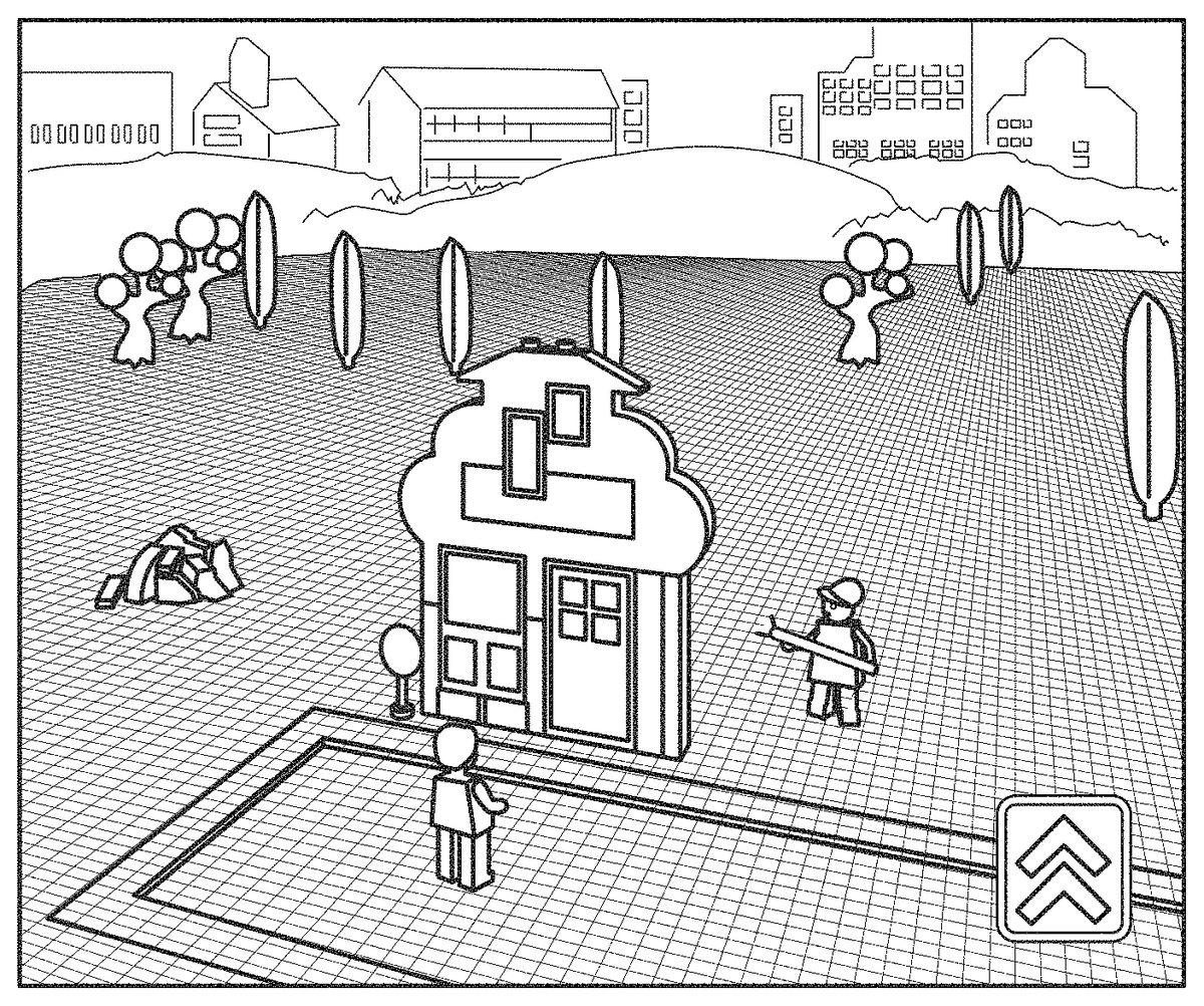
Finally, the newly added virtual object, represented as a 3D graphical representation1460, is modelled as part of the virtual environment with which virtual characters1461may interact, e.g. enter the building through a door, look out a window, climb in or out of a window, etc. e.g. as illustrated byFIG. 14H.
FIG. 15illustrates an exemplary user interface that allows a user to construct a virtual construction model from virtual construction elements, resulting in a digital representation of a virtual construction model. The user interface allows a user to select a virtual construction element from a selection area, in this example a list of construction elements, represented graphically in an element selection area1562, also referred to as palette. The user interface may be provided on a display of a user system, such as a suitably programmed computer or other data processing system. Using an input device of the user system (e.g., mouse, keyboard, trackball, touch screen, etc.) the user can select virtual construction elements from the palette1562and assemble a virtual construction model1565in a virtual building area1563. An exemplary process and user interface for placing and assembling virtual construction elements in a 3D scene is described in WO 2004/104811, the entire contents of which are incorporated herein by reference. The element selection area1562may be divided into a number of different sub-palettes, each sub-palette including different types of elements, thereby making it easier for a user to identify any desired element. The process may establish and maintain a data structure representing the virtual construction model1565and the data structure may comprise connectivity information e.g. using techniques such as those described in WO 2004/034333, the entire contents of which are incorporated herein by reference. The constructed model may subsequently be used as a virtual object in a virtual environment where the system implementing the virtual environment may set virtual attributes of the created virtual object based on one or more visible characteristics of the constructed model. Accordingly, the user interface of the construction environment may display current values of one or more virtual attributes1564of the virtual object, if the virtual object is created based on the virtual construction model1565in its currently displayed form. Whenever the user adds a new construction element to the model, removes a construction element from the model or repositions one of the construction elements, the system may re-compute the virtual attributes and display the updated values. Consequently, the user may easily monitor the consequences of the building activities on the attributes of the resulting virtual object or character.
To this end, each virtual construction element may have associated with it certain attributes, such as a colour, a weight or volume, and the process may determine a total weight or volume of the model or a dominant colour, and/or similar characteristics of the model from the corresponding characteristics of the individual construction elements. Moreover, the process may determine other visible attributes of the model, such as an aspect ratio, the relative size of certain parts of the model, a measure of connectedness, etc.
In the example of FIG. the model1565is a racing car which may subsequently be used in a virtual car racing game. The attributes of a car in the racing game may include one or more of the following: acceleration, top speed, safety, handling, traction, toughness. These and/or other attributes may determine how the virtual car in the racing game responds to user inputs and/or interactions with other cars or the environment.
The above attributes may, at least in part, be determined by visible attributes of the virtual construction model1565. For example, the total weight or volume of the model may have a strong negative impact on the acceleration of the car and a small negative impact on the top speed and the handling of the car. Similarly the total volume or weight may have a strong positive impact on the safety and the traction of the car and a small positive impact on the toughness. The impact of each characteristics may e.g. be modelled by the following equation: A=A0+w·C, where A is the virtual attribute (e.g. total speed) A0 is a base value of the attribute before the characteristic is taken into account, C is a characteristic influencing the attribute A (e.g. the total volume of the model), and w is a weight factor, where a negative weight factor corresponds to negative impact and a positive weight factor corresponds to positive impact.
Other examples of characteristics of the model1565that influence the virtual attributes of a virtual car in a car racing game include the shape of the model, e.g. a sloping angle of a frontal area (which is a measure of the aerodynamics of the virtual car), the number of virtual connection members interconnecting respective virtual construction elements in the model (which may have positive impact on parameters such as toughness, safety, handling, etc.), the size of the wheels, the (dominant) colour of the model, the presence of specific types of construction elements, e.g. elements representing certain engine parts, spoilers, etc.
Generally, in an alternative embodiment, the system may present the selectable toy construction elements in the selection area in a different manner. For example, the virtual construction elements in the selection area may be displayed as a simulated heap of arbitrarily positioned virtual construction elements. The user interface may then provide functionality allowing a user to select a virtual construction element from the simulated heap and to reposition the selected construction element within the selection area. The selection area may be a display area separate from the building area or combined with the building area. For example the elements in the simulated heap may surround the constructed model. Generally, the individual virtual construction elements in the heap may each be modelled as a solid object having a predetermined weight. Movement of one of the virtual element responsive to a user interaction, e.g. by clicking on the element with a mouse or by touching its representation on a touchscreen, may be modelled using a physics simulation engine. The physics simulation engine may be configured to model the movements of the virtual construction elements in the heap under a simulated gravity and responsive to a simulated force imparted on one of the elements by a user interaction and responsive to collisions of virtual elements with each other.
Selection of a virtual construction element from the heap may be implemented in a number of different ways, e.g. by dragging an element from the selection area to the building area, by double clicking/tabbing on the selected element, and/or the like.
Embodiments of the method described herein can be implemented by means of hardware comprising several distinct elements, and/or at least in part by means of a suitably programmed microprocessor.
In the claims enumerating several means, several of these means can be embodied by one and the same element, component or item of hardware. The mere fact that certain measures are recited in mutually different dependent claims or described in different embodiments does not indicate that a combination of these measures cannot be used to advantage.
It should be emphasized that the term “comprises/comprising” when used in this specification is taken to specify the presence of stated features, elements, steps or components but does not preclude the presence or addition of one or more other features, elements, steps, components or groups thereof.
Claims
- A computer-implemented method of manipulating a three-dimensional virtual construction model assembled from a plurality of virtual construction elements, the method comprising: displaying a representation of a virtual construction model on a display;displaying a plurality of virtual construction elements as a simulated heap of arbitrarily positioned virtual construction elements and computing a virtual attribute of a virtual object represented by the virtual construction model;and allowing a user to select one or more virtual construction elements and to add the selected virtual construction element to the virtual construction model;wherein the virtual construction elements are only positionable in a discrete number of relative positions and/or orientations with respect to each other and/or be interconnected with each other at predetermined connection points;wherein allowing a user to select one or more virtual construction elements comprises allowing a user to select a virtual construction element from the simulated heap and to reposition the selected construction element within a selection area, wherein repositioning a virtual construction element is not restricted by construction rules of the virtual construction elements in the virtual construction model;and wherein the method further comprises modelling movements of the virtual construction elements in the heap under a simulated gravity and responsive to a simulated force imparted on one of the virtual construction elements by a user interaction and responsive to collisions of virtual elements with each other.
- The method according to claim 1 , wherein the virtual construction model and the plurality of virtual construction elements are presented in a virtual environment.
- The method according to claim 2 , wherein the virtual attribute of the virtual object is associated with a behavioural characteristic of the virtual object, and wherein the virtual attribute has a value based on one or more determined visual attribute parameters.
- The method according to claim 3 , wherein the virtual attribute is indicative of one of: a speed of movement of the virtual object in the virtual environment;a behavioural pattern of an at least partly autonomous virtual object;and a need or preference of the at least partly autonomous virtual object.
- The method according to claim 3 , wherein the virtual object is configured to interact with the virtual environment based on the one or more determined visual attribute parameters.
- The method according to claim 3 , further comprising detecting a presence of one or more visual features of the virtual construction model.
- The method according to claim 2 , further comprising dynamically re-computing the virtual attribute responsive to adding one of the plurality of virtual construction elements to the virtual construction model.
- The method according to claim 2 , wherein: the virtual attribute of the virtual object is associated with a behavior of the virtual object, wherein the behavior is controllable by one or more behaviour simulation rules.
- The method according to claim 1 , wherein each of the plurality of virtual construction elements comprises a top surface, a bottom surface, and coupling members placed on at least one of the top and the bottom surfaces.
- A data processing system comprising computer program code configured to cause, when the computer program code is executed by the data processing system, the data processing system to perform the steps of the method defined in claim 1 .
- A computer program product comprising computer program code configured to cause, when executed by a data processing system, the data processing system to perform the steps of the method defined in claim 1 .
Disclaimer: Data collected from the USPTO and may be malformed, incomplete, and/or otherwise inaccurate.