Illustrative Figure
Abstract
A game controller includes a housing; a top panel disposed on an opening portion of the housing and having a manipulation input surface; a position detector configured to detect a position of a manipulation input performed on the manipulation input surface; a vibrating element configured to generate a vibration in the manipulation input surface of the top panel; and a drive controlling part configured to drive the vibrating element by using a driving signal causing the vibrating element to generate a natural vibration in an ultrasound-frequency-band in the manipulation input surface.
Description
DESCRIPTION OF EMBODIMENT Hereinafter, an embodiment to which a game controller of the present invention is applied will be described. An object is to provide a game controller that can provide a user with fine tactile sensations when operating the game controller. FIG. 1is a perspective view of a game controller100according to an embodiment. The game controller100includes a housing110and two touch panels150. The game controller100is a so-called remote controller connected to a game machine body by a wire or radio. The game controller100is manipulated by a user who performs a manipulation input on the touch panels150with fingertips or the like to operate a game machine body. Because the game controller100includes the two touch panels150, the user can manipulate the two touch panels150with both hands while holding the game controller100with both hands. For example, an acceleration sensor or a gyro sensor may be incorporated in the game controller100. In this case, the user can change an angle of the game controller100and can shake the game controller100to manipulate the game machine body in addition to manipulating the game machine body via the touch panels150. Buttons may be disposed on the game controller100. Next, a specific peripheral configuration of the touch panel150of the game controller100is described with reference toFIG. 2. FIG. 2is a diagram illustrating the touch panel150of the game controller100and its specific peripheral configuration according to the embodiment in plan view.FIG. 3is a diagram illustrating a cross-sectional view taken along a line A-A ofFIG. 2. The touch panel150and its specific peripheral configuration illustrated inFIG. 2correspond to one of the two touch panels150and its specific peripheral configuration illustrated inFIG. 1. A XYZ coordinate system as an orthogonal coordinate system is defined as illustrated inFIGS. 2 and 3. The game controller100includes the housing110, a top panel120, a double-faced adhesive tape130, a vibrating element140, the ...
DESCRIPTION OF EMBODIMENT
Hereinafter, an embodiment to which a game controller of the present invention is applied will be described. An object is to provide a game controller that can provide a user with fine tactile sensations when operating the game controller.
FIG. 1is a perspective view of a game controller100according to an embodiment.
The game controller100includes a housing110and two touch panels150. The game controller100is a so-called remote controller connected to a game machine body by a wire or radio.
The game controller100is manipulated by a user who performs a manipulation input on the touch panels150with fingertips or the like to operate a game machine body. Because the game controller100includes the two touch panels150, the user can manipulate the two touch panels150with both hands while holding the game controller100with both hands.
For example, an acceleration sensor or a gyro sensor may be incorporated in the game controller100. In this case, the user can change an angle of the game controller100and can shake the game controller100to manipulate the game machine body in addition to manipulating the game machine body via the touch panels150.
Buttons may be disposed on the game controller100.
Next, a specific peripheral configuration of the touch panel150of the game controller100is described with reference toFIG. 2.
FIG. 2is a diagram illustrating the touch panel150of the game controller100and its specific peripheral configuration according to the embodiment in plan view.FIG. 3is a diagram illustrating a cross-sectional view taken along a line A-A ofFIG. 2. The touch panel150and its specific peripheral configuration illustrated inFIG. 2correspond to one of the two touch panels150and its specific peripheral configuration illustrated inFIG. 1. A XYZ coordinate system as an orthogonal coordinate system is defined as illustrated inFIGS. 2 and 3.
The game controller100includes the housing110, a top panel120, a double-faced adhesive tape130, a vibrating element140, the touch panel150, and a substrate170.
The housing110is made of a plastic, for example. As illustrated inFIG. 3, the substrate170and the touch panel150are contained in a concave portion110A of the housing110, and the top panel120is adhered to the housing110by the double-faced adhesive tape130. The rectangular concave portion110A in plan view is formed on the housing110. Thereby, a rectangular opening formed by the concave portion110A is present in the housing110. InFIG. 2, this opening is substantially coincident with a rectangular opening of the double-faced adhesive tape130having a rectangular-ring shape. InFIG. 2, the touch panel150is positioned inside of the rectangular opening of the concave portion110A.
The top panel120is a plate-shaped member having a rectangular shape in plan view and is made of glass or a reinforced plastic such as polycarbonate. A surface of the top panel120which is located on a positive side in Z axis direction is one example of a manipulation input surface into which the user of the game controller100performs a manipulation input.
The vibrating element140is bonded on a surface of the top panel120which is located on a negative side in Z axis direction, and four sides in plan view of the top panel120are adhered to the housing110by the double-faced adhesive tape130. Herein, the double-faced adhesive tape130is not necessarily a rectangular-ring-shaped member in plan view as illustrated inFIG. 3, as long as the double-faced adhesive tape130can adhere four sides of the top panel120to the housing110.
The touch panel150is disposed on the negative side in Z axis direction of the top panel120. The top panel120is provided in order to protect the surface of the touch panel150. Another panel, protection film or the like may be provided on the surface of the top panel120.
In a state where the vibrating element140is bonded to the surface of the top panel120located on the negative side in Z axis direction, the top panel120vibrates if the vibrating element140is being driven. In the embodiment, a standing wave is generated in the top panel120by causing the top panel120to vibrate at a natural vibration frequency (natural resonance frequency or eigenfrequency) of the top panel120. Since the vibrating element140is bonded to the top panel120, it is preferable to determine the natural vibration frequency in consideration of a weight of the vibrating element140of the like, in a practical manner.
The vibrating element140is bonded on the surface of the top panel120which is located on the negative side in Z axis direction at a location along the short side extending in X axis direction at a positive side in Y axis direction. The vibrating element140may be any element as long as it can generate vibration an ultrasound-frequency-band. A piezoelectric element such as a piezo element is used as the vibrating element140, for example.
The vibrating element140is driven in accordance with a driving signal output from the drive controlling part which will be described later. An amplitude (intensity) and a frequency of the vibration output from the vibrating element140is set (determined) by the driving signal. An on/off action of the vibrating element140is controlled in accordance with the driving signal.
The ultrasound-frequency-band is a frequency band which is higher than or equal to about 20 kHz, for example. According to the game controller100of the embodiment, the frequency at which the vibrating element140vibrates is equal to a number of vibrations per unit time (frequency) of the top panel120. Accordingly, the vibrating element140is driven in accordance with the driving signal so that the vibrating element140vibrates at a number of natural vibrations per unit time (natural vibration frequency) of the top panel120.
The touch panel150is disposed on an upper side (positive side in Z axis direction) of the substrate170and is disposed on a lower side (negative side in Z axis direction) of the top panel120. The touch panel150is one example of a coordinate detector which detects a position at which the user of the game controller100touches the top panel120. Hereinafter, the position is referred to as a position of the manipulation input.
The touch panel150is any coordinate detector as long as it can detect the position of the manipulation input onto the top panel120performed by the user. The touch panel150may be a capacitance type coordinate detector or a resistance film type coordinate detector, for example. Hereinafter, the embodiment in which the touch panel150is the capacitance type coordinate detector will be described. In a case where the touch panel150is a capacitance type, the touch panel150can detect the manipulation input performed on the top panel120even if there is a clearance gap between the touch panel150and the top panel120.
Although the top panel120is disposed on the manipulation input surface side of the touch panel150in the present embodiment, the top panel120may be integrated with the touch panel150. In this case, the surface of the touch panel150is equal to the surface of the top panel120as illustrated inFIGS. 2 and 3, and the surface of the touch panel150becomes the manipulation input surface. Otherwise, the top panel120as illustrated inFIGS. 2 and 3may be omitted. In this case, the surface of the touch panel150constitutes the manipulation input surface. In this case, the vibrating element140vibrates the manipulation input surface at a natural vibration frequency of a member having the manipulation input surface.
In a case where the touch panel150is a capacitance type, the touch panel150may be disposed on the top panel120. In this case, the surface of the touch panel150constitutes the manipulation input surface. In a case where the touch panel150is a capacitance type, the top panel120as illustrated inFIGS. 2 and 3may be omitted. In this case, the surface of the touch panel150constitutes the manipulation input surface. In this case, the vibrating element140vibrates the manipulation input surface at a natural vibration frequency of a member having the manipulation input surface.
The substrate170is disposed inside of the concave portion110A of the housing110. The touch panel150is disposed on the substrate170. The touch panel150is fixed to the substrate170and the housing110by a holder or the like (not shown).
On the substrate170, a drive controlling apparatus which will be described hereinafter and circuits or the like that are necessary for driving the game controller100are mounted.
In the game controller100having the configuration as described above, when the user touches the top panel120with the fingertip and a movement of the fingertip is detected, the drive controlling part mounted on the substrate170drives the vibrating element140so that the top panel120vibrates at a frequency in the ultrasound-frequency-band. The frequency in the ultrasound-frequency-band is a resonance frequency of a resonance system including the top panel120and the vibrating element140. A standing wave is generated in the top panel120at the frequency.
The game controller100generates the standing wave in the ultrasound-frequency-band in the top panel120to provide a tactile sensation (haptic sensation) to the user through the top panel120.
Next, the standing wave generated in the top panel120is described with reference toFIGS. 4A and 4B.
FIGS. 4A and 4Bare diagrams illustrating crests and troughs of the standing wave formed in parallel with the short side of the top panel120included in the standing waves generated in the top panel120by the natural vibration in the ultrasound-frequency-band.FIG. 4Aillustrates a side view, andFIG. 4Billustrates a perspective view. InFIGS. 4A and 4B, a XYZ coordinate system similar to that described inFIGS. 2 and 3is defined. InFIGS. 4A and 4B, the amplitude of the standing wave is overdrawn in an easy-to-understand manner. The vibrating element140is omitted inFIGS. 4A and 4B.
The natural vibration frequency (the resonance frequency) f of the top panel120is represented by formulas (1) and (2) where E is the Young's modulus of the top panel120, ρ is the density of the top panel120, δ is the Poisson's ratio of the top panel120, l is the long side dimension of the top panel120, t is the thickness of the top panel120, and k is a periodic number of the standing wave along the direction of the long side of the top panel120. Because the standing wave has the same waveforms in every half cycle, the periodic number k takes values at 0.5 intervals. The periodic number k takes 0.5, 1, 1.5, 2 . . . .
f=πk2tl2E3ρ(1-δ2)(1)f=αk2(2)
The coefficient α included in formula (2) corresponds to coefficients other than k2included in formula (1).
A waveform of the standing wave as illustratedFIGS. 4A and 4Bis obtained in a case where the periodic number k is 10, for example. In a case where a sheet of Gorilla (registered trademark) glass of which the length l of the long side is 140 mm, the length of the short side is 80 mm, and the thickness t is 0.7 mm is used as the top panel120, for example, the natural vibration number f is 33.5 kHz, if the periodic number k is 10. In this case, a frequency of the driving signal is 33.5 kHz.
The top panel120is a planar member. If the vibrating element140(seeFIGS. 2 and 3) is driven and the natural vibration in the ultrasound-frequency-band is generated in the top panel120, the top panel120is bent as illustrated inFIGS. 4A and 4B. As a result, the standing wave is generated in the surface of the top panel120.
In the present embodiment, the single vibrating element140is bonded on the surface of the top panel120which is located on the negative side in Z axis direction at the location along the short side extending in X axis direction at the positive side in Y axis direction. The game controller100may include two vibrating elements140for the single top panel120. In a case where the game controller100includes two vibrating elements140, another vibrating element140may be bonded on the surface of the top panel120which is located on the negative side in Z axis direction at a location along the short side extending in X axis direction at a negative side in Y axis direction. In this case, the two vibrating elements140may be symmetrically disposed with respect to a center line of the top panel120parallel to the two short sides of the top panel120.
In a case where the game controller100includes two vibrating elements140, the two vibrating elements140may be driven in the same phase, if the periodic number k is an integer number. If the periodic number k is an odd number, the two vibrating elements140may be driven in opposite phases.
Next, the natural vibration at ultrasound-frequency-band generated in the top panel120of the game controller100is described with reference toFIGS. 5A and 5B.
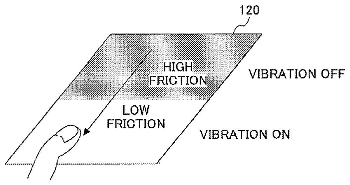
FIGS. 5A and 5Bare diagrams illustrating cases where a kinetic friction force applied to the fingertip varies when the natural vibration in the ultrasound-frequency-band is generated in the top panel120of the game controller100. InFIGS. 5Aand5B, the manipulation input is performed with the fingertip. InFIGS. 5A and 5B, the user touches the top panel120with the fingertip and performs the manipulation input by tracing the top panel120with the fingertip in a direction from a far side to a near side with respect to the user. An on/off state of the vibration is switched by controlling an on/off state of the vibrating element140(seeFIGS. 2 and 3).
InFIGS. 5A and 5B, areas which the fingertip touches while the vibration is being turned off are indicated in grey in the depth direction of the top panel120. Areas which the fingertip touches while the vibration is being turned on are indicated in white in the depth direction of the top panel120.
As illustrated inFIGS. 4A and 4B, the natural vibration in the ultrasound-frequency-band occurs on an entire surface of the top panel120.FIGS. 5A and 5Billustrate operation patterns in which the on/off state of the natural vibration is switched while the user's fingertip is tracing the top panel120from the far side to the near side.
Accordingly, inFIGS. 5A and 5B, areas which the fingertip touches while the vibration is being turned off are indicated in grey in the depth direction of the top panel120. Areas which the fingertip touches while the vibration is being turned on are indicated in white in the depth direction of the top panel120.
In the operation pattern as illustrated inFIG. 5A, the vibration is turned off when the user's fingertip is located on the far side of the top panel120, and the vibration is turned on in the process of tracing the top panel120with the fingertip toward the near side.
On the contrary, in the operation pattern as illustrated inFIG. 5B, the vibration is turned on when the user's fingertip is located on the far side of the top panel120, and the vibration is turned off in the process of tracing the top panel120with the fingertip toward the near side.
In a state where the natural vibration in the ultrasound-frequency-band is generated in the top panel120, a layer of air intervenes between the surface of the top panel120and the fingertip. The layer of air is provided by a squeeze film effect. As a result, a kinetic friction coefficient on the surface of the top panel120is decreased when the user traces the surface with the fingertip.
Accordingly, in the grey area located on the far side of the top panel120as illustrated inFIG. 5A, the kinetic friction force applied to the fingertip increases. In the white area located on the near side of the top panel120, the kinetic friction force applied to the fingertip decreases.
Therefore, the user who is performing the manipulation input to the top panel120in a manner as illustrated inFIG. 5Asenses a reduction of the kinetic friction force applied to the fingertip when the vibration is turned on. As a result, the user senses a slippery or smooth touch (texture) with the fingertip. In this case, the user senses as if a concave portion were present on the surface of the top panel120when the surface of the top panel120becomes slippery and the kinetic friction force decreases.
On the contrary, in the white area located on the far side of the top panel120as illustrated inFIG. 5B, the kinetic friction force applied to the fingertip decreases. In the grey area located on the near side of the top panel120, the kinetic friction force applied to the fingertip increases.
Therefore, the user who is performing the manipulation input in the top panel120in a manner as illustrated inFIG. 5Bsenses an increase of the kinetic friction force applied to the fingertip when the vibration is turned off. As a result, the user senses a grippy or scratchy touch (texture) with the fingertip. In this case, the user senses as if a convex portion were present on the surface of the top panel120when the surface of the top panel120becomes grippy and the kinetic friction force increases.
Accordingly, the user can sense a concavity or convexity with the fingertip in the cases as illustrated inFIGS. 5A and 5B. For example, “The Printed-matter Typecasting Method for Haptic Feel Design and Sticky-band Illusion” (the Collection of papers of the 11th SICE system integration division annual conference (SI2010, Sendai)_174-177, 2010-12) discloses that a human can sense a concavity or a convexity. “Fishbone Tactile Illusion” (Collection of papers of the 10th Congress of the Virtual Reality Society of Japan (September, 2005)) discloses that a human can sense a concavity or a convexity as well.
Although a variation of the kinetic friction force when the vibration is switched on or off is described above, a variation of the kinetic friction force similar to those described above is obtained when the amplitude (intensity) of the vibrating element140is varied.
In the following, a configuration of the game controller100according to the embodiment is described with reference toFIG. 6.
FIG. 6is a diagram illustrating the configuration of the game controller100according to the embodiment.FIG. 6illustrates a display panel510and a game machine body500connected to the game controller100by a wire or radio.
The game controller100includes the vibrating element140, an amplifier141, the touch panel150, a driver Integrated Circuit (IC)151, a controlling apparatus200, a sinusoidal wave generator310, and an amplitude modulator320.
The controlling apparatus200includes an control processor220, a drive controlling part240, and a memory250. The controlling apparatus200is realized by an IC chip, for example.
Although an embodiment in which the control processor220, the communication processor230, the drive controlling part240and the memory250are included in the single controlling apparatus200is described, the drive controlling part240may be disposed outside of the controlling apparatus200and realized by another IC chip or a processor. In this case, data which is necessary for a drive control performed by the drive controlling part240among data stored in the memory250may be stored in another memory.
InFIG. 6, the housing110, the top panel120, the double-faced adhesive tape130, and the substrate170(seeFIG. 2) are omitted. Herein, the amplifier141, the driver IC151, the control processor220, the drive controlling part240, the memory250, the sinusoidal wave generator310, and the amplitude modulator320are described.
The amplifier141is disposed between the amplitude modulator320and the vibrating element140. The amplifier141amplifies the driving signal output from the amplitude modulator320and drives the vibrating element140.
The driver IC151is connected to the touch panel150. The driver IC151detects position data representing the position on the touch panel150at which the manipulation input is performed and outputs the position data to the controlling apparatus200. As a result, the position data is input to the control processor220and the drive controlling part240.
The control processor220performs control processing except for controlling processing performed by the drive controlling part240among control processing of the game controller100.
The drive controlling part240outputs amplitude data to the amplitude modulator320. The amplitude data represents an amplitude value used for controlling an intensity of the driving signal used for driving the vibrating element140. The amplitude data that represents the amplitude value may be stored in the memory250.
The game controller100of the embodiment causes the top panel120to vibrate in order to vary the kinetic friction force applied to the user's fingertip when the fingertip traces along the surface of the top panel120.
There are various manipulation inputs such as a flick operation, a swipe operation and a drag operation, for example, that the user performs when the user moves the fingertip along the surface of the top panel120.
The flick operation is performed by flicking (snapping) the surface of the top panel120for a relatively-short distance with the fingertip. The swipe operation is performed by swiping the surface of the top panel120for a relatively-long distance with the fingertip. The drag operation is performed by moving the fingertip along the surface of the top panel120while selecting a button or the like displayed on the display panel510when the user slides the button of the like.
The manipulation inputs that are performed by moving the fingertip along the surface of the top panel120, such as the flick operation, the swipe operation and the drag operation that are introduced as examples, are used differently depending on a kind of a display by an application. Accordingly, when it is determined whether the position of the fingertip performing the manipulation input is within a designated area which requires generating the vibration, the kind of the application activated by the game controller100is concerned to the determination.
The memory250stores the amplitude data, representing the amplitude, and pattern data, representing vibration patterns. In the memory250, data that is necessary to be associated with each other among the data as described above may be stored as table format data using identifiers and the like, for example.
The memory250stores data, programs, and the like that are necessary for the control processor220to execute the control processing.
The sinusoidal wave generator310generates sinusoidal waves used for generating the driving signal which causes the top panel120to vibrate at the natural vibration frequency. For example, in a case of causing the top panel120to vibrate at 33.5 kHz of the natural vibration frequency f, a frequency of the sinusoidal waves becomes 33.5 kHz. The sinusoidal wave generator310inputs a sinusoidal wave signal in the ultrasound-frequency-band to the amplitude modulator320.
The amplitude modulator320generates the driving signal by modulating an amplitude of the sinusoidal wave signal input from the sinusoidal wave generator310based on the amplitude data input from the drive controlling part240. The amplitude modulator320modulates only the amplitude of the sinusoidal wave signal in the ultrasound-frequency-band input from the sinusoidal wave generator310and does not modulate a frequency and a phase of the sinusoidal wave signal in order to generate the driving signal.
Therefore, the driving signal output from the amplitude modulator320is a sinusoidal wave signal in the ultrasound-frequency-band obtained by modulating only the amplitude of the sinusoidal wave signal in the ultrasound-frequency-band input from the sinusoidal wave generator310. In a case where the amplitude data is zero, the amplitude of the driving signal becomes zero. This is the same as the amplitude modulator320not outputting the driving signal.
The game controller100is connected to the game machine body500via a cable or radio such as a wireless Local Area Network (LAN) or Bluetooth (registered trademark). The user who operates the game machine body500performs the manipulation input on the top panel120of the game controller100.
The game controller100transmits, to the game machine body500, a manipulation signal that represents a content of the manipulation input performed on the surface of the top panel120. The game machine body500controls an image displayed on the display panel510in accordance with progress of a video game and performs control based on the manipulation signal input from the game controller100.
For example, in a case where the manipulation is performed to move an object such as a vehicle or a man, a pointer, a cursor or the like displayed on the display panel510, a starting point of the manipulation input performed on an arbitrary position on the surface of the top panel120corresponds to a display position of the object, the pointer, the cursor or the like.
Movements of the manipulation input performed on the top panel120correspond to movements of the object, the pointer, the cursor or the like. The movements of the manipulation input relative to the starting point correspond to relative movements of the object, the pointer, the cursor or the like in a display screen on the display panel510.
Among data necessary for the game machine body500to control the screen, coordinate data is input to the game controller100from the game machine body500. The coordinate data represents coordinate positions in the screen of the image relating to driving of the vibrating element140.
The drive controlling part240of the game controller100drives the vibrating element140in accordance with the manipulation input on the surface of the top panel120and drives the vibrating element140in accordance with the coordinate data input from the game machine body500.
FIG. 7is a diagram illustrating a state in which the manipulation input is performed on the surface of the top panel120of the game controller100according to the embodiment. The touch panel150(seeFIGS. 2 and 3) is disposed on the back side of the top panel120, though it is not illustrated inFIG. 7.
FIG. 8is a diagram illustrating an example of an operation of the game controller100according to the embodiment.FIG. 8illustrates driving patterns for driving the vibrating element140in accordance with the manipulation input illustrated inFIG. 7. InFIG. 8, a horizontal axis represents time, and a vertical axis represents an amplitude value of the amplitude data.
As illustrated inFIG. 7, in a case where the manipulation input is performed along an arrow on the surface of the top panel120, the vibrating element140is turned on at a point of time at which the manipulation input starts, and the vibrating element140is turned off when a movement amount of the manipulation input from the starting point121reaches a designated movement amount.
For example, the vibrating element140is turned on when the drag operation is performed from the starting point121illustrated inFIG. 7. The vibrating element140is turned off when the position of the manipulation input passes positions represented by three dashed lines L1, L2, and L3.
The three dashed lines L1, L2, and L3inFIG. 7are illustrated for representing the movement amount from the starting point in a direction of movement of the manipulation input. The movement amount determined here is a relative amount of movement relative to the starting point121.
In the operation of the vibrating element140illustrated inFIG. 7, the drive controlling part240outputs the amplitude data of which the amplitude value is A1and the vibrating element140is turned on when the manipulation input is performed at a time t1as illustrated inFIG. 8.
The position of the manipulation input stops and does not move from the time t1until a time t2. Because the manipulation input is performed between the time t1and the time t2, the drive controlling part240continuously outputs the amplitude data of which the amplitude value is A1and the vibrating element is held in an on-state.
When the position of the manipulation input starts to move at the time t2, the drive controlling part240continuously outputs the amplitude data of which the amplitude value is A1and the vibrating element is held in the on-state. Because the kinetic friction coefficient applied to the user's fingertip is decreased by the squeeze film effect, the fingertip becomes easy to move over the surface of the top panel120.
When the movement amount of the manipulation input reaches a designated movement amount corresponding to a length from the starting point121(seeFIG. 7) to the first dashed line L1at the time t3, the drive controlling part240sets the amplitude value of the amplitude data to zero. In this way, the vibrating element140is turned off.
When the vibrating element140is turned off, the user senses an increase of the kinetic friction force applied to the fingertip. As a result, the user senses a grippy or scratchy touch (texture) with the fingertip. In this case, the user senses as if a convex portion were present on the surface of the top panel120when the surface of the top panel120becomes grippy and the kinetic friction force increases.
The vibrating element140is turned off only for a time period TP1. The time period TP1may be about 50 milliseconds, for example. When the time period TP1has elapsed, the drive controlling part240outputs the amplitude data of which the amplitude value is A1and the vibrating element is turned on again.
When the movement amount of the manipulation input reaches a movement amount corresponding to a length from the starting point121(seeFIG. 7) to the second dashed line L2at a time t4, the drive controlling part240sets the amplitude value of the amplitude data to zero. In this way, the vibrating element140is turned off and the kinetic friction force applied to the fingertip increases. Thereby, the user feels as if the convex portion were present on the surface of the top panel120.
The vibrating element140is turned off only for the time period TP1. When the time period TP1has elapsed, the drive controlling part240outputs the amplitude data of which the amplitude value is A1and the vibrating element is turned on again.
When the movement amount of the manipulation input reaches a movement amount corresponding to a length from the starting point121(seeFIG. 7) to the third dashed line L3at a time t5, the drive controlling part240sets the amplitude value of the amplitude data to zero. In this way, the vibrating element140is turned off and the kinetic friction force applied to the fingertip increases. Thereby, the user feels as if the convex portion were present on the surface of the top panel120.
The vibrating element140is turned off only for the time period TP1. When the time period TP1has elapsed, the drive controlling part240outputs the amplitude data of which the amplitude value is A1and the vibrating element is turned on again.
Because the movement of the manipulation input is stopped at a time t6and the manipulation input is performed by the fingertip touching the surface of the top panel120until a time t7, the drive controlling part240continuously outputs the amplitude data of which the amplitude value is A1and the vibrating element140is held in the on-state.
When the fingertip separates from the surface of the top panel120and the manipulation input is stopped at the time t7, the drive controlling part240sets the amplitude value of the amplitude data to zero and the vibrating element140is turned off.
FIG. 9is a diagram illustrating a flowchart executed by the drive controlling part240of the game controller100according to the embodiment.
An operating system (OS) of the game controller100executes control for driving the game controller100with respect to every designated control cycle. Accordingly, the drive controlling part240repeatedly executes the flow illustrated inFIG. 9with respect to every designated control cycle.
Before processing is started, the drive controlling part240does not output the amplitude data and the vibrating element140is in the off-state.
The drive controlling part240starts the processing when the power source of the game controller100is turned on.
The drive controlling part240determines whether the manipulation input is present (step S1). The drive controlling part240may determine presence/absence of the manipulation input based on whether the position data is input from the driver IC151(FIG. 6).
When the drive controlling part240determines that the manipulation input is present, (yes at step S1), the drive controlling part240uses the driving signal having the amplitude A1to drive the vibrating element140(step S2). In this way, the natural vibration in the ultrasound-frequency-band is generated in the top panel120.
When the drive controlling part240determines that the manipulation input is present, the drive controlling part240stores coordinates from which the manipulation input is started as the starting point. Position data input first from the driver IC151(seeFIG. 6) may be used as the coordinates from which the manipulation input is started.
Next, the drive controlling part240determines whether the manipulation input is present (step S3). This is to determine whether the manipulation input continues.
When the drive controlling part240determines that the manipulation input is present (yes at step S3), the drive controlling part240determines whether the movement amount of the manipulation input from the starting point reaches any of relative positions (step S4). Any of the relative positions are the positions of the three dashed lines L1, L2, and L3relative to the starting point121illustrated inFIG. 7, and are determined by a distance from the starting point121in the direction of movement of the manipulation input. InFIG. 7, the relative positions relative to the starting point121are determined by distances between the starting point121and the respective three dashed lines L1, L2, and L3in the direction of movement of the manipulation input represented by the arrow.
When the drive controlling part240determines that the movement amount of the manipulation input from the starting point reaches any of the relative positions (yes at step S4), the drive controlling part240turns off the driving signal for the time period TP1(step S5). In this way, the natural vibration in the ultrasound-frequency-band of the top panel120is turned off for the time period TP1. As described above, the time period TP1may be set to be 50 milliseconds, for example.
When the process at step S5ends, the drive controlling part240returns the flow to step S3.
When the drive controlling part240determines that the manipulation input is not present (no at step S1), the drive controlling part240repeatedly executes the process of step S1. This is because the series of processes illustrated inFIG. 9is started when the manipulation input is performed.
When the drive controlling part240determines that the manipulation input is not present (no at step S3), the series of processes ends (END). When the series of processes ends, the vibrating element140is turned off.
When the drive controlling part240determines that the movement amount does not reach any of relative positions (no at step S4), the flow returns to step S3.
The series of processes as described above is repeatedly executed while the power source of the game controller100is turned on.
In a case where the position of the manipulation input reaches the dashed line L1at the time t3, the position of the manipulation input reaches the dashed line L2at the time t4, and the position of the manipulation input reaches the dashed line L3at the time t5as illustrated inFIGS. 7 and 8, the flow proceeds as follows.
First, because the manipulation input is performed at the time t1, the drive controlling part240determines “YES” at step S1, and the vibrating element is turned on at step S2.
Subsequently, because the position of the manipulation input stops and does not move from the time t1until the time t2, the drive controlling part240determines “YES” at step S3and determines “NO” at step S4. From the time t1until the time t2, subroutine processing at steps S3and S4are repeatedly executed. The vibrating element140is held in the on-state from the time t1to the time t2.
When the position of the manipulation input starts to move at the time t2and the position of the manipulation input reaches the dashed line L1at the time t3, the drive controlling part240determines “YES” at step S4and turns off the vibrating element140for the time period TP1at step S5. When the time period TP1has elapsed from the time t3, the drive controlling part240turns on the vibrating element140.
After that, when the position of the manipulation input reaches the dashed line L2at the time t4, the drive controlling part240determines “YES” at step S4and turns off the vibrating element140for the time period TP1at step S5. When the time period TP1has elapsed from the time t4, the drive controlling part240turns on the vibrating element140.
After that, when the position of the manipulation input reaches the dashed line L3at the time t5, the drive controlling part240determines “YES” at step S4and turns off the vibrating element140for the time period TP1at step S5. When the time period TP1has elapsed from the time t5, the drive controlling part240turns on the vibrating element140.
When the position of the manipulation input stops at the time t6, the drive controlling part240determines “NO” at step S4. From the time t6until the time t7, subroutine processing at steps S3and S4are repeatedly executed and the vibrating element140is held in the on-state. This is because the manipulation input is continuously performed.
When the manipulation input is stopped at the time t7, the drive controlling part240determines “NO” at step S3and the series of processes ends (END). In this way, the vibrating element140is turned off.
For example, in a case where the user's fingertip separates from the top panel120and the manipulation input is stopped at the point of time at which the position of the manipulation input reaches the dashed line L1at the time t3, the drive controlling part240determines “NO” at step S3while the vibrating element140is turned off for the time period TP1from the time t3. Thereby, the series of processes ends (END) without turning on the vibrating element140again. For this reason, the control cycle of the series of processes illustrated inFIG. 9may be set shorter than the time period TP1.
The distance between the starting point121and each of the three dashed lines L1, L2, and L3in the direction of movement of the manipulation input represented by the arrow illustrated inFIG. 7may be set to an unit manipulation amount in the manipulation when the user plays the video game, for example. For example, in a case where the video game is a game for driving an automobile, the unit manipulation amount may be set to an amount corresponding to one increment of strength of a brake, degree of opening of an accelerator, a manipulation amount of a steering wheel or the like.
When the unit manipulation amount is set as described above, the tactile sensation can be provided to the user's fingertip as if the convex portion were present every time the manipulation amount reaches the unit manipulation amount. As a result, a fine operational feeling can be realized.
FIG. 10is a diagram illustrating a state in which the manipulation input is performed on the surface of the top panel120of the game controller100according to the embodiment. The touch panel150(seeFIGS. 2 and 3) is disposed on the back side of the top panel120.
FIG. 11is a diagram illustrating an example of an operation of the game controller100according to the embodiment.FIG. 11illustrates driving patterns for driving the vibrating element140in accordance with the manipulation input illustrated inFIG. 10. InFIG. 11, a horizontal axis represents time, and a vertical axis represents the amplitude value of the amplitude data.
As illustrated inFIG. 10, the manipulation input is performed by the drag operation along an arrow on the surface of the top panel120. It is supposed that the manipulation input is performed to move an object such as a vehicle or a man displayed on the display panel510.
When the position of the manipulation input passes designated positions P1and P2on the top panel120, the drive controlling part240turns on the vibrating element140for a very short time period.
If the drive controlling part240drives the vibrating element140as described above, the kinetic friction force applied to the fingertip decreases while the vibrating element140is turned on for the very short time period, and the kinetic friction force applied to the fingertip increases when the vibrating element140is turned off. Thereby, the fine tactile sensation can be provided to the user's fingertip as if the convex portion were present.
The above described processing can be realized by calculating coordinates of the designated positions P1and P2relative to the current position of the manipulation input of the top panel120based on data that represents a relative positional relationship between a current display position of the object displayed on the display screen of the display panel510and a designated spot in a traveling direction the object, for example.
When the object moves in the display screen of the display panel510and passes the designated spot in accordance with the manipulation input of the user playing the video game with the game controller100, the position of the manipulation input passes the designated positions P1and P2on the top panel120.
Accordingly, when the object, which moves in accordance with the manipulation input, passes the designated spot in the display screen on the display panel510, the drive controlling part240turns on the vibrating element140for the very short time period to cause the user to feel that the object has passed the designated spot through the tactile sensations.
For example, the designated spot in the display screen on the display panel510may be set to a boundary between areas in the display screen, a spot that gives a point in accordance with the pass or the like.
The operation of the vibrating element140illustrated inFIG. 10is described as follows with reference toFIG. 11.
When the manipulation input is performed at a time t11, the drive controlling part240outputs the amplitude data of which the amplitude value is zero and the vibrating element140is in an off-state.
The position of the manipulation input stops and does not move from the time t11until a time t12. The vibrating element140is held in the off-state from the time t11to the time t12.
When the position of the manipulation input starts to move at the time t12and the position of the manipulation input reaches the position P1(seeFIG. 10) at a time13, the drive controlling part240sets the amplitude value of the amplitude data to A1for the very short time period TP11. In this way, the vibrating element140is turned on for the time period TP11.
Because the kinetic friction coefficient applied to the user's fingertip is decreased by the squeeze film effect when the vibrating element140is turned on, the fingertip becomes easy to move over the surface of the top panel120.
When the time period TP11ends at a time t14, the drive controlling part240sets the amplitude value of the amplitude data to zero. In this way, the user feels as if the convex portion were present on the surface of the top panel120when the vibrating element140is turned off and the kinetic friction force applied to the fingertip increases.
The time period TP1for turning on the vibrating element140may be about 100 milliseconds, for example.
When the position of the manipulation input moves from the time t14until the time t15and the position of the manipulation input reaches the position P2(seeFIG. 10) at the time t15, the drive controlling part240sets the amplitude value of the amplitude data to A1for the very short time period TP11. In this way, the vibrating element140is turned on for the time period TP11.
Because the kinetic friction coefficient applied to the user's fingertip is decreased by the squeeze film effect when the vibrating element140is turned on, the fingertip becomes easy to move over the surface of the top panel120.
When the time period TP11ends, the drive controlling part240sets the amplitude value of the amplitude data to zero. In this way, the user feels as if the convex portion were present on the surface of the top panel120when the vibrating element140is turned off and the kinetic friction force applied to the fingertip increases.
The position of the manipulation input is stopped at the time t16and the manipulation input is performed by the fingertip touching the surface of the top panel120until the time t17. The vibrating element140is held in the off-state until the time t17.
At the time t17, the fingertip separates from the top panel120and the manipulation input is stopped.
FIG. 12is a diagram illustrating a state in which the manipulation input is performed on the surface of the top panel120of the game controller100according to the embodiment. The touch panel150(seeFIGS. 2 and 3) is disposed on the back side of the top panel120.
FIG. 13is a diagram illustrating an example of an operation of the game controller100according to the embodiment.FIG. 13illustrates driving patterns for driving the vibrating element140in accordance with the manipulation input illustrated inFIG. 12. InFIG. 13, a horizontal axis represents time, and a vertical axis represents an amplitude value of the amplitude data.
As illustrated inFIG. 12, the manipulation input is performed by the drag operation along an arrow on the surface of the top panel120. It is supposed that the manipulation input is performed to move an object such as a vehicle or a man displayed on the display panel510.
While the position of the manipulation input passes a designated zone S on the top panel120, the drive controlling part240uses the amplitude data of which the amplitude temporally changes in a random manner to turn on the vibrating element140.
When the vibrating element140is driven as described above, the kinetic friction force applied to the fingertip varies in accordance with the temporal change of the amplitude data. When the amplitude is large, the kinetic friction force is relatively small. When the amplitude is small, the kinetic friction force is relatively large.
Based on such a temporal variation of the kinetic friction force, a feel can be provided to the user's fingertip as if concave portions and convex portions having random heights were present on the surface of the top panel120. The feel is provided to the user's fingertip as if the surface of the top panel120were rough.
For example, in a case where the object such as the vehicle or the man displayed on the display screen of the display panel510passes a zone having many obstacles, the vibrating element140may be driven by using the amplitude data of which the amplitude temporally changes in the random manner as described above.
The coordinates of the designated positions P1and P2in the top panel120can be calculated by calculating coordinates of an end point and a starting point of the zone S relative to the current position of the manipulation input of the top panel120based on data that represents a relative positional relationship between a current display position of the object displayed on the display screen of the display panel510and positions of an end point and a starting point of the zone having many obstacles displayed on the display screen.
For example, the vibrating element140may be driven by using the amplitude data using random numbers so that amplitude values are output in time series in order to temporally change the amplitude in the random manner. Such amplitude data may be stored in the memory250(seeFIG. 6).
When the object moves in the display screen of the display panel510and passes the zone having many obstacles in accordance with the manipulation input of the user playing the video game with the game controller100, the position of the manipulation input passes the zone S on the top panel120.
Accordingly, when the object passes the zone having many obstacles in the display screen of the display panel510, the drive controlling part240drives uses the amplitude data of which the amplitude temporally changes in the random manner to turn on the vibrating element140. Thereby, the user can feel that the object has passed the zone having many obstacles through the tactile sensations.
The operation of the vibrating element140illustrated inFIG. 12is described as follows with reference toFIG. 13.
When the manipulation input is performed at a time t21, the drive controlling part240outputs the amplitude data of which the amplitude value is zero and the vibrating element140is in an off-state.
The position of the manipulation input stops and does not move from the time t21until a time t22. The vibrating element140is held in the off-state from the time t21to the time t22.
When the position of the manipulation input starts to move at the time t22and the position of the manipulation input reaches a starting point of the zone S (seeFIG. 12) at a time t23, the drive controlling part240uses the amplitude data of which the amplitude temporally changes in the random manner to turn on the vibrating element140.
The driving of the vibrating element140depending on the amplitude data of which the amplitude temporally changes in the random manner continues from the time t23until the time t24. Then, the drive controlling part240turns off the vibrating element140at the time t24.
Because the kinetic friction coefficient applied to the user's fingertip is decreased by the squeeze film effect when the vibrating element140is turned on, the fingertip becomes easy to move over the surface of the top panel120.
In the time period from the time t23until the time t24, a feel can be provided to the user's fingertip as if the surface of the top panel120were rough because the drive controlling part240uses the amplitude data of which the amplitude temporally changes in the random manner.
After the vibrating element140is turned off at the time t24, the manipulation input is performed until the time t25and the drive controlling part240sets the amplitude value of the amplitude data to zero.
Then, the manipulation input is stopped at the time t25.
In addition to the above described processes, the drive controlling part240may set the amplitude value in accordance with a temporal change degree of the position data.
Here, a moving speed of the user's fingertip tracing along the surface of the top panel120is used as the temporal change degree of the position data. The drive controlling part240may calculate the moving speed of the user's fingertip based on a temporal change degree of the position data input from the driver IC151.
The higher the moving speed becomes, the smaller the game controller100controls the amplitude value to be, in order to make the tactile sensation sensed by the user constant regardless of the moving speed of the fingertip, for example. The lower the moving speed becomes, the greater the game controller100controls the amplitude value to be, in order to make the tactile sensation constant regardless of the moving speed of the fingertip, for example.
Data which represents a relationship between the amplitude data, representing the amplitude value, and the moving speed may be stored in the memory250.
Although the amplitude value in accordance with the moving speed is set by using the data that represents the relationship between the amplitude data representing the amplitude value and the moving speed in the present embodiment, the amplitude value A may be calculated based on formula (3). The higher the moving speed becomes, the smaller the amplitude value A calculated by formula (3) becomes. The lower the moving speed becomes, the greater the amplitude value A calculated by formula (3) becomes.
A=A0/√{square root over (|V|/a)} (3)
“A0” is a reference value of the amplitude, “V” represents the moving speed of the fingertip and “a” is a designated constant value. In a case where the amplitude value A is calculated by using formula (3), data representing formula (3) and data representing the reference value A0and the designated constant value a may be stored in the memory250.
The drive controlling part240causes the vibrating element140to vibrate when the moving speed becomes greater than or equal to a designated threshold speed.
Accordingly, the amplitude value represented by the amplitude data output from the drive controlling part240becomes zero in a case where the moving speed is less than the designated threshold speed. The amplitude value is set to a designated amplitude value corresponding to the moving speed in a case where the moving speed is greater than or equal to the designated threshold speed. In a case where the moving speed is greater than or equal to the designated threshold speed, the higher the moving speed becomes, the smaller the amplitude value becomes. In a case where the moving speed is greater than or equal to the designated threshold speed, the lower the moving speed becomes, the greater the amplitude value becomes.
In a case where the moving speed of the fingertip is greater than or equal to the designated threshold speed, the drive controlling part240reads the amplitude data, which represents the amplitude value in accordance with the moving speed, from the memory250to output the amplitude data to the amplitude modulator320.
FIG. 14is a diagram illustrating the data which represents the relationship between the amplitude data representing the amplitude value and the moving speed stored in the memory250.
According to the data as illustrated inFIG. 14, the amplitude value is set to 0 in a case where the moving speed V is greater than or equal to 0 and less than b1(0<=V<b1), the amplitude value is set to A1in a case where the moving speed V is greater than or equal to b1and less than b2(b1<=V<b2), and the amplitude value is set to A2in a case where the moving speed V is greater than or equal to b2and less than b3(b2<=V<b3).
For example, the amplitude values of the driving patterns illustrated inFIGS. 8 and 11may be set in accordance with the moving speed of the fingertip as the data illustrated inFIG. 14.
Because the kinetic friction force applied to the user's fingertip is varied by generating the natural vibration in the ultrasound-frequency-band of the top panel120, the game controller100according to the embodiment can provide the fine tactile sensations to the user.
The game controller100of the embodiment generates the driving signal by causing the amplitude modulator320to modulate only the amplitude of the sinusoidal wave in the ultrasound-frequency-band output from the sinusoidal wave generator310. The frequency of the sinusoidal wave in the ultrasound-frequency-band generated by the sinusoidal wave generator310is equal to the natural vibration frequency of the top panel120. The natural vibration frequency is set in consideration of the vibrating element140.
The driving signal is generated by the amplitude modulator320modulating only the amplitude of the sinusoidal wave in the ultrasound-frequency-band generated by the sinusoidal wave generator310without modulating the frequency or the phase of the sinusoidal wave.
Accordingly, it becomes possible to generate the natural vibration of the top panel120in the ultrasound-frequency-band in the top panel120and to reduce the kinetic friction coefficient applied to the fingertip tracing the top panel120with absolute certainty by utilizing the layer of air provided by the squeeze film effect. It becomes possible to provide fine tactile sensations to the user as if the concave portion and the convex portion were present on the surface of the top panel120by utilizing the Sticky-band Illusion effect or the Fishbone Tactile Illusion effect.
In the embodiment as described above, in order to provide the tactile sensations to the user as if the concave portions and the convex portions were present on the top panel120, the vibrating element140is switched on or off. Turning off the vibrating element140is equal to setting the amplitude value represented by the driving signal used to drive the vibrating element140to zero.
However, it is not necessary to turn off the vibrating element140from a being turned on state. For example, the vibrating element140may be driven based on the drive signal having a small amplitude instead of turning off the vibrating element140. For example, the game controller100may provide the tactile sensations as if the concave portion and the convex portion were present on the surface of the top panel120to the user by reducing the amplitude to about one-fifth of that of the turned on state.
In this case, the vibrating element140is driven by the drive signal in a manner that the vibration of the vibrating element140is switched between a strong level and a weak level. As a result, the strength of the natural vibration generated in the top panel120is switched between the strong level and the weak level. It becomes possible to provide the tactile sensations as if the concave portion and the convex portion were present on the surface of the top panel120to the user's fingertip.
If the game controller100turns off the vibrating element140when making the vibration weaker in order to switch the vibration of the vibrating element140from the strong level to the weak level, the vibrating element140is switched off. Switching on and off the vibrating element140means driving the vibrating element140intermittently.
When the tactile sensations as if the concave portion and the convex portion were present on the top panel120, a degree of decreasing the amplitude value of the amplitude data may be adjusted in accordance with the moving speed of the fingertip.
FIGS. 15A and 15Bare diagrams illustrating driving patterns for adjusting the degree of decreasing the amplitude value of the amplitude data in accordance with the moving speed of the fingertip.
When decreasing the amplitude value in order to increase the kinetic friction force applied to the fingertip, the driving patterns illustrated inFIG. 15Adecrease, at a time t31and a time t32, the amplitude value to A01from a state where the amplitude value is set to A1and the vibrating element140is turned on. For example, the amplitude value A01is one-fifth of the amplitude value A1.
In contrast, when decreasing the amplitude value in order to increase the kinetic friction force applied to the fingertip, the driving patterns illustrated inFIG. 15Bdecrease, at the time t31and the time t32, the amplitude value to A02from a state where the amplitude value is set to A1and the vibrating element140is turned on. For example, the amplitude value A02is four-fifths of the amplitude value A1.
For example, in a case where the moving speed is higher than the designated value, the driving patterns ofFIG. 15Aare used to decrease the amplitude value to A01when the amplitude value is decreased in order to increase the kinetic friction force applied to the fingertip because there is a tendency that the fingertip is easy to feel the concavo-convex tactile sensations when the moving speed is high.
In a case where the moving speed is equal to or less than the designated value, the driving patterns ofFIG. 15Bare used to decrease the amplitude value to A02when the amplitude value is decreased in order to increase the kinetic friction force applied to the fingertip.
Tactile sensations different in accordance with the moving speed of the fingertip can be provided to the user by adjusting the amplitude value of the amplitude data in accordance with the moving speed of the fingertip as described above.
Although the game controller100includes the two touch panels150as illustrated inFIG. 1, the number of touch panels150may be one.
FIG. 16is a diagram illustrating a game controller100A of a variation example of the embodiment. The game controller100A includes one touch panel150disposed on an opening portion of a housing110B. A button111A is also disposed on the housing110A. The housing110B is vertically long. The user may hold a lower side inFIG. 16with one hand and manipulate the touch panel150disposed on an upper side with the other hand. The game controller100A has a shape particularly suitable for manipulation with an index finger of the other hand.
Although examples of a game controller according to the embodiment of the present invention have been described, the present invention is not limited to the embodiment specifically disclosed and various variations and modifications may be made without departing from the scope of the present invention.
All examples and conditional language provided herein are intended for pedagogical purposes of aiding the reader in understanding the invention and the concepts contributed by the inventors to further the art, and are not to be construed as limitation to such specifically recited examples and conditions, nor does the organization of such examples in the specification relate to a showing of superiority and inferiority of the invention. Although one or more embodiments of the present invention have been described in detail, it should be understood that various changes, substitutions, and alterations could be made hereto without departing from the sprit and scope of the invention.
Claims
- A game controller comprising: a housing having an opening portion;a top panel disposed on the opening portion and having a manipulation input surface;a position detector configured to detect a position of a manipulation input performed on the manipulation input surface of the top panel;a vibrating element configured to generate a vibration in the manipulation input surface of the top panel;and a drive controlling part configured to drive the vibrating element with a driving signal causing the vibrating element to generate a natural vibration in an ultrasound-frequency-band in the manipulation input surface of the top panel;wherein the drive controlling part is configured to turn on, in response to a start of the manipulation input performed on the manipulation input surface, the vibrating element with the driving signal to set the vibrating element in an ON state, continuously hold the vibrating element in the ON state until the position of the manipulation input starts moving from a starting point on the manipulation input surface, turn off the vibrating element with the driving signal to change the ON state of the vibrating element to an OFF state upon a movement amount of the position of the manipulation input on the manipulation input surface from the starting point reaching a predetermined distance from the starting point, and turn on, upon the OFF state of the vibrating element being continued over a predetermined period of time, the vibrating element with the driving signal to set the vibrating element in the ON state again.
- The game controller as claimed in claim 1 , wherein the drive controlling part drives the vibrating element so as to vary an intensity of the natural vibration in accordance with the position of the manipulation input performed on the manipulation input surface and a temporal change degree of the position.
- The game controller as claimed in claim 1 , wherein the drive controlling part drives the vibrating element so as to vary an intensity of the natural vibration when the position of the manipulation input passes a designated position corresponding to a position in a content displayed based on image data of a game.
- The game controller as claimed in claim 1 , wherein the driving signal causes the vibrating element to generate the natural vibration in the ultrasound-frequency-band in the manipulation input surface, the natural vibration having a constant frequency and a constant phase.
- The game controller as claimed in claim 1 , wherein the manipulation input surface has a rectangular shape having long sides and short sides in plan view, and wherein the drive controlling part causes the vibrating element to vibrate so that a standing wave of which amplitude varies along the long side occurs on the manipulation input surface.
Disclaimer: Data collected from the USPTO and may be malformed, incomplete, and/or otherwise inaccurate.