U.S. Pat. No. 10,507,385
Game Controller
Issue DateJanuary 25, 2017
Illustrative Figure
Abstract
The invention relates to a game controller for controlling the play of computerized games, more particularly, but not exclusively, the invention relates to ergonomics and control systems which can be programmed and customized. A game controller can include removable and replaceable ergonomic grips to accommodate and fit users having small, medium, and large hand sizes. Further, a game controller can include a removable and replaceable gate which can be circular, octagonal, square, diamond, or other geometric shape for customizing the play of at least one joystick or thumbstick control. In addition, a game controller can include customizable paddle controls mounted on the bottom side of the handle portions of the game controller. Alternatively, a game controller can include a plurality of control keys, or touch pad controls mounted on the bottom side of the handle portions. Moreover, a game controller can include touch pad controls for a majority and/or all of the various desired operations and functions of the device.
Description
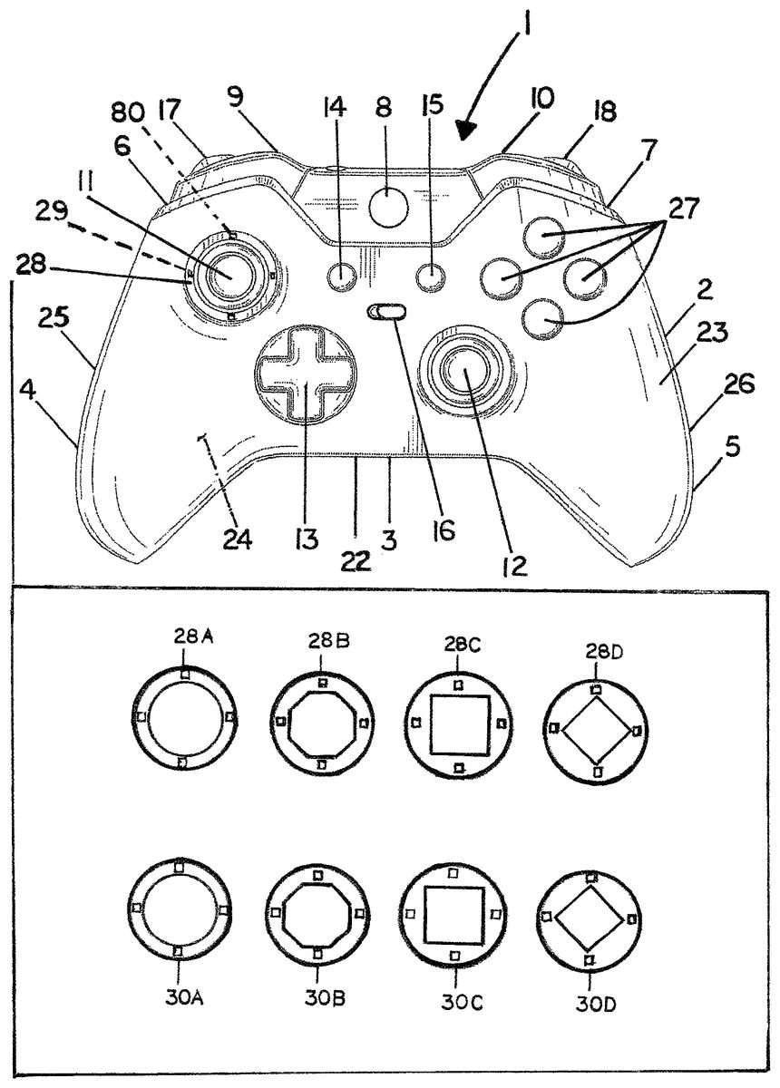
DETAILED DESCRIPTION Detailed descriptions of specific embodiments of the game controller and its actuator mechanisms and other features are disclosed herein. It can be readily understood that the disclosed embodiments are merely examples of the way in which certain aspects of the invention can be implemented and do not represent all of the ways the invention may be embodied. The game controller and its actuator mechanisms and other features described herein may be embodied in various alternative forms. Further, the drawing figures are not necessarily to scale and some features may be enlarged or minimalized to show certain details and features of particular embodiments. Some well-known structures, components, features, materials, and methods are not necessarily described in great detail for the sake of brevity and in order to focus upon the present invention. Any specific structural and functional details disclosed herein are not to be interpreted as limiting, but rather are provided for teaching one skilled in the art to variously employ the invention, and as basis for the claims. FIG. 1is a top view of a game controller1according to one embodiment including a left thumbstick control11and a right thumbstick control12located asymmetrically relative to the left handle portion4, the middle portion3, and the right handle portion5of the game controller1similar to the Microsoft Xbox One® game controller which is believed to be represented in U.S. D709,882 S by Morris et al. The embodiment of a game controller1shown inFIG. 1includes a case2having a front side21, back side22, top side23, bottom side24, left side25, right side26, left shoulder portion6, a right shoulder portion7, a middle portion3, a left handle portion4, and a right handle portion5. As shown, the top view of the controller1shows an on and off control8, a left selection control14which can be used as a back control switch and for other ...
DETAILED DESCRIPTION
Detailed descriptions of specific embodiments of the game controller and its actuator mechanisms and other features are disclosed herein. It can be readily understood that the disclosed embodiments are merely examples of the way in which certain aspects of the invention can be implemented and do not represent all of the ways the invention may be embodied. The game controller and its actuator mechanisms and other features described herein may be embodied in various alternative forms. Further, the drawing figures are not necessarily to scale and some features may be enlarged or minimalized to show certain details and features of particular embodiments. Some well-known structures, components, features, materials, and methods are not necessarily described in great detail for the sake of brevity and in order to focus upon the present invention. Any specific structural and functional details disclosed herein are not to be interpreted as limiting, but rather are provided for teaching one skilled in the art to variously employ the invention, and as basis for the claims.
FIG. 1is a top view of a game controller1according to one embodiment including a left thumbstick control11and a right thumbstick control12located asymmetrically relative to the left handle portion4, the middle portion3, and the right handle portion5of the game controller1similar to the Microsoft Xbox One® game controller which is believed to be represented in U.S. D709,882 S by Morris et al. The embodiment of a game controller1shown inFIG. 1includes a case2having a front side21, back side22, top side23, bottom side24, left side25, right side26, left shoulder portion6, a right shoulder portion7, a middle portion3, a left handle portion4, and a right handle portion5. As shown, the top view of the controller1shows an on and off control8, a left selection control14which can be used as a back control switch and for other functions, a right selection control15which can be used as a menu control switch and for other functions, a mapping preset control16for changing between a plurality of mapping presets, a left trigger control9and a left bumper control17on the left shoulder portion6, a right trigger control10and a right bumper control on the right shoulder portion7, four action controls27which can be labeled A, B, X, and Y, and a cross-shaped directional pad control13. Other mechanical controllers and switches for possible use in a game controller can be push button, slide, rocking, rotating, throwing, pulling, key-turning, magnetic, and toggle actuated.
FIG. 2is a bottom view of the game controller1shown inFIG. 1. Unlike, the Microsoft Xbox One® and Microsoft Xbox One Elite® game controllers which are believed to be represented in U.S. D709,882 S by Morris et al. and U.S. D772,988 S by Kujawski et al., the embodiment which is shown inFIG. 1includes paddle controls19which are secured on the left handle portion4, and also the right handle portion5of the game controller1. The game controller1shown inFIG. 2also includes a left bumper control17and left trigger control9on the left shoulder portion6, a right bumper control18and a right trigger control10on the right shoulder portion7, and two hair trigger lock controls20.
FIG. 3is a front view of the game controller1shown inFIG. 1showing a left trigger control9and a left bumper control17on the left shoulder portion6, and a right trigger control10and a right bumper control18on the right shoulder portion7of the game controller1, and a portion of the two paddle controls19can also be seen.
FIG. 4is a top view of a game controller1according to one embodiment which is generally similar to that shown inFIG. 1, but having a symmetrical placement of the left thumbstick control11and right thumbstick control12on the top side23.
FIG. 5is a bottom view of a game controller1according to one embodiment that is generally similar to that shown inFIG. 2, but which includes two paddle controls19on the left handle portion4and two paddle controls19on the right handle portion5of the game controller1. It can be readily understood that users normally have five fingers on their hands including the thumb. Counting the thumb as the first finger, the index finger is the second finger, the middle finger is the third finger, and the fourth finger, and then the fifth finger which is normally the smallest. In this regard, the paddle controls19can be actuated by a user's third or middle finger and also a user's fourth and fifth fingers.
FIG. 6is a bottom view of a game controller1according to one embodiment that is generally similar to that shown inFIG. 5, but which further includes two controls on the middle portion3of the game controller1. The two controls can be a toggle or paddle controls, and other mechanical controllers and switches for possible use in a game controller can be push button, slide, rocking, rotating, throwing, pulling, key-turning, and magnetic actuated.
FIG. 7is a top view of a game controller1according to one embodiment which has a left thumbstick control11and a right thumbstick control12located symmetrically relative to the left handle portion4, the middle portion3, and the right handle portion5of the game controller1on the top side23similar to the Sony® PS4 game controller which is believed to be represented in U.S. D715,296 S by Huang. The game controller1shown inFIG. 7includes a case2having a front side21, back side22, top side23, bottom side24, left side25, right side26, a left shoulder portion6, a right shoulder portion7, a middle portion3, a left handle portion4, and a right handle portion5. As shown, the top view of the controller1shows an on and off control8, a left selection control14which can be used as a back control and for other functions, a right selection control15which can be used as a menu control and for other functions, a control16for changing between mapping presets, a left trigger control9on the left shoulder portion6, a right trigger control10on the right shoulder portion7, four action controls27which can be labeled A, B, X, and Y, a cross-shaped directional pad control13, and a touch control screen77.
FIG. 8is a bottom plan view of the game controller1shown inFIG. 7, but which includes a paddle control19on the left handle portion4and a paddle control19on the right handle portion5of the game controller1. Unlike, the Microsoft Xbox One® and Microsoft Xbox One Elite® game controllers which are believed to be represented in U.S. D709,882 S by Morris et al. and U.S. D772,988 S by Kujawski et al., the embodiment which is shown inFIG. 7includes paddle controls19which are secured on the left handle portion4, and also the right handle portion5of the game controller1. The game controller1shown inFIG. 8also includes a left bumper control17and left trigger control9on the left shoulder portion6, a right bumper control18and a right trigger control10on the right shoulder portion7, and two hair trigger lock controls20.
FIG. 9is a front view of the game controller shown inFIG. 7showing a left trigger control9and a left bumper control17on the left shoulder portion6, and a right trigger control10and a right bumper control18on the right shoulder portion7of the game controller1, and a portion of the paddle controls19, and a touch screen control77can also be seen.
FIG. 10is a bottom plan view of a game controller1according to one embodiment that is generally similar to that shown inFIG. 8, but which includes two paddle controls19on the left handle portion4and two paddle controls19on the right handle portion5of the game controller1.
FIG. 11is a bottom plan view of a game controller1according to one embodiment that is generally similar to that shown inFIG. 8, but which further includes two paddle controls19in the middle portion of the game controller1.
FIG. 12is a cross-section view of the left handle portion4of the game controller1shown inFIG. 8taken along line44, showing a portion of the interior side42of the case2and a push button control switch39which can be actuated by paddle control19. The control mount38and switch39for use can be generally similar to those disclosed in the drawingFIGS. 5, 6, 15, 16, and the specification of published U.S. Patent Application 20160346682 A1 by Burgess et al., and/or as shown and discussed herein. For example, U.S. 20160346682 A1 by Burgess et al. shows in drawingFIG. 5a portion of a game controller including four single pole push button momentary control switches that are normally associated with open circuits in the rest position and which can be made to make contact and close their corresponding circuits enabling electrical energy to flow to the game console logic board or other destination where user activation of the switch is sensed when actuated with a paddle control by a user. In this regard, when actuated a paddle control depresses the bush button on the control switch below to close the corresponding circuit. A similar structure and push bottom control switch39can be used in a game controller1according to the embodiment which is shown inFIG. 8, herein. Alternatively, the paddle control switch39could include a normally closed switch39associated with a closed circuit which goes to ground in the rest position. In this regard, the control switch39can be single pole push button momentary control switch that is normally associated with a first closed circuit81which goes to ground when in the closed and resting position, but which can be made to open and therefore break the first closed circuit81which goes to ground and thereby cause electrical energy to instead flow in a second closed circuit82to the game console logic board or other destination where user activation of the switch is sensed when the control switch39is actuated with the paddle control19by a user. One possible advantage of the latter type of normally closed switch and wiring configuration is that it could possibly require less movement and deflection for effective operation and/or less wear on the contact surfaces resulting in greater durability.
FIG. 13is a cross-sectional view showing a portion of the interior side42of the case2of a game controller1and a push button control switch39according to one embodiment which can be activated with a paddle control19by a user which is generally similar to that shown inFIG. 8, taken along line44. The paddle control19design and sideways position of the push button control switch39is such that depressing the paddle control19causes the control switch39to be actuated. The push button control switch39can be a single pole push button momentary control switch39that is normally associated with an open circuit in the rest position and which can be made to make contact and close its corresponding circuit enabling electrical energy to flow to the game console logic board or other destination where user activation of the switch is sensed when the paddle control19is actuated by a user. Alternatively, the control switch39can be single pole push button momentary control switch that is normally associated with a first closed circuit81which goes to ground in the normally closed and resting position, but which can be made to break and open the first closed circuit81which goes to ground and thereby cause electrical energy to instead flow in a second closed circuit82to the game console logic board or other destination where user activation of the control switch39is sensed when the control switch39is actuated with a paddle control19by a user.
FIG. 14is a schematic view which relates to a portion of the case2of an alternative embodiment of a game controller1and a control switch39according to one embodiment which can be activated with a paddle control19including a contact41. The control switch39is normally associated with a first closed circuit81which goes to ground in the closed and resting position, but which can be made to break and open the first closed circuit81which goes to ground and thereby cause electrical energy to instead flow in a second closed circuit82which is no longer grounded, and then to the game console logic board or other destination where user activation of the control switch39is sensed when the control switch39is actuated with a paddle control19by a user. As shown inFIG. 14, the second closed circuit82which goes to the game console logic board or other destination where user activation of the control switch39is sensed is on one side or portion of a contact41and the first closed circuit81which goes to ground is located in close proximity on another side or portion of the contact41, but is not in direct electronic communication with the second closed circuit82. The paddle control19includes a corresponding contact41which is electrically conductive so that when the control switch39is in the normal closed and resting position there is electronic communication between the first closed circuit81and the second closed circuit82which effectively grounds the second closed circuit82. However, when the paddle control19is actuated, the electronic communication between the first closed circuit81which goes to ground and the second closed circuit82is broken, and there is then electronic communication to the game console logic board or other destination where user activation of the control switch39is sensed when the control switch39is actuated by the paddle control19.
FIG. 15is a cross-sectional view of a portion of the case2of a game controller1and a control switch39according to one embodiment which is generally similar to that shown inFIG. 8, taken along line44, and which can be activated with a paddle control19by a user. The paddle control19design and sideways position of the control switch39spring40and contact41is such that depressing the paddle control19causes the control switch39to be actuated. As shown, the control switch39is normally associated with a first closed circuit81which goes to ground in the closed and resting position, but can be made to break and open the first closed circuit81which goes to ground and thereby cause electrical energy to instead flow in a second closed circuit82to the game console logic board or other destination where user activation of the control switch39is sensed when the control switch39is actuated with a paddle control19by a user.
FIG. 16is a cross-sectional view of a portion of the case2of a game controller1and a control switch39according to one embodiment which is generally similar to that shown inFIG. 8, taken along line44, and which can be activated with a paddle control19by a user. The paddle control19design and approximately vertical position of the control switch39spring40and contact41is such that depressing the paddle control19causes the control switch39to be actuated. As shown, the control switch39is normally associated with a first closed circuit81which goes to ground in the closed and resting position, but can be made to break and open the first closed circuit81which goes to ground and thereby cause electrical energy to instead flow in a second closed circuit82to the game console logic board or other destination where user activation of the control switch39is sensed when the control switch39is actuated with a paddle control19by a user.
FIG. 17is a cross-sectional view of a portion of the case2of a game controller1and a control switch39according to one embodiment which is generally similar to that shown inFIG. 8, taken along line44, and which can be activated with a paddle control19by a user. The paddle control19design and external position of the control switch39spring40and contact41is such that depressing the paddle control19causes the control switch39to be actuated. As shown, the control switch39is normally associated with a first closed circuit81which goes to ground in the closed and resting position, but can be made to break and open the first close circuit81which goes to ground and thereby cause electrical energy to instead flow in a second closed circuit82to the game console logic board or other destination where user activation of the control switch39is sensed when the control switch39is actuated with a paddle control19by a user. In this alternative embodiment of a game controller1, the paddle control19, control mount38, retaining pin46, spring40, and contact41are all on the exterior side43of the case2which can facilitate customization and also removal and replacement of component parts. In this regard, different configurations of alternative paddle controls19, but also different alternative springs40having different stiffness, and also different alternative contacts41can be used as desired by a user to customize a game controller1for game play. The contact41can include a conductive metal, but also a plastic, thermoplastic or rubber material which can serve as a pad. In this regard, the inclusion of carbon black can render a thermoplastic or rubber material electrically conductive. Further, different paddle control19and switch39embodiments can be removably attached to game controllers1according to alternative embodiments using different structures and means, e.g., a paddle control19can alternatively include: an opening45for receiving a removable retaining pin46as shown inFIG. 18; an integral axle47for snap-fitting into a mating female receptacle as shown inFIG. 19; a semi-circular receptacle48for mating with a pin fixed in the case2or a removable retaining pin46as shown inFIG. 20; an opening45for receiving a screw49as shown inFIG. 21; and, a magnet50as shown inFIG. 22, and the like.
FIG. 23is a top plan view of a game controller1generally similar to that shown inFIG. 1, showing a case2including at least one receptacle29for receiving different alternative removable retaining rings28having different geometric shapes for possible use in securing and customizing the play of a joystick control such as thumbstick control11and/or thumbstick control12. The different alternative retaining rings28can include an integral gate30and/or secure a gate30comprising a particular geometric shape for customizing the play of at least one joystick control such as thumbstick control11and/or thumbstick control12. As shown in the box portion ofFIG. 23different optional retaining rings28including an integral gate30such as a circular retaining ring28A, octagonal retaining ring28B, square retaining ring28C, or a diamond retaining ring28D can include four male snap fit appendages79for inserting into mating female snap fit openings80. Alternatively, individual removable circular gate30A, octagonal gate30B, square gate30C, or diamond gate30D can include registered notches and/or openings45for permitted the snap fit appendages79on a circular retaining ring28A to pass therethrough and then be removably secured to the receptacle29portion of the case2are also shown. A selectively removable retaining ring28and/or gate30can have a geometric shape selected from the group consisting of: a circular shape, an octagonal shape, a square shape, a diamond shape, and other geometric shapes. The retaining rings28and/or gates30can be associated with 8 way, 4 way, 2 way, and other functions and operations associated with game play.
FIG. 24is a top view of a game controller1similar to that shown inFIG. 1showing different customizable and selectively removable ergonomic left grip31and right grip32for accommodating users having small, medium, and large hand sizes. In particular, the left grip31and right grip32can be removably attached using a friction fit, Velcro® loop and pile, adhesive means such as self-adhesive strips36having a peel ply layer37, screws, rivets, snap-fit structures, other mating male and female structures, and the like. The left grip31can extend along a portion of the left side25of the case2in an area between the left shoulder6and back side22of the left handle4, and the right grip32can extend along a portion of the right side26of the case2in an area between the right shoulder7and back side22of the right handle5in order to better fit the palm of a user's hand as desired. The left grip31and right grip32can then be customized and removably attached to best fit the hand size, comfort, and gaming preference of the user. In the top view shown inFIG. 24, the small size left grip31S and right grip32S can fit flush or nearly flush with the case2, but the medium size left grip31M and right grip32M and also the large size left grip31L and right grip32L can project by different amounts from the normal profile of the case2. Shown inFIG. 24is a game controller1including small size left grip31-S installed, and also showing a medium left grip31-M, a large left grip31-L, and a small right grip32-S which are relatively symmetrical in shape, but also a medium right grip32-MASYM and large right grip32-LASYM which have an asymmetrical shape. In this regard, it is possible to reverse and flip the direction of the asymmetrical grips so that the thicker portion can be either placed closer to the front21or the back22of the game controller1. Moreover, it is possible that a user may desire and choose to use one sized grip31having a particular symmetrical or asymmetrical configuration on the left side25and a different sized grip32on the right side26of the game controller1.
FIG. 25is a right side26view of the game controller1shown inFIG. 7. As shown inFIG. 12, the right grip32can be customized and removably secured to the right side26of the right handle5in a location between the shoulder7and the back side22of the right handle5. In this regard, the case2can include a female recess33for inserting a male portion34of the right grip32. A male portion of the right grip32can then be removably friction fit and/or snap fit in place on the right side26of the right handle5to secure the right grip32. If desired, a double sided strip of self-adhesive tape36having a peel ply layer37can also be applied to the male portion34of the right grip32in order to help secure it in place, as shown on the right side ofFIG. 24. Optionally, Velcro® loop and pile, screws, rivets, mechanical snap-fit, and other mating male and female structures can be used, and the like.
FIG. 26is a top view of a resilient stretch to fit game control cover75which can be made using a silicone or thermoplastic rubber material, and in ergonomic configurations to fit users having small75S, medium75M, and large75L hand sizes.
FIG. 27is bottom view of a game controller1according to one embodiment which can include controls and features resembling those shown on the top side23of the embodiment shown inFIG. 1, but instead includes on the bottom side24two push keys51and52on the right handle portion5, a push key53on the right part of the middle portion3, two push keys54and55on the left handle portion4, and another push key56on the left part of the middle portion3for actuating control switches39, and on the front side21near the right shoulder portion7includes a push right trigger key64and right bumper key65, and on the front side21near the left shoulder portion6includes a push left trigger key69and left bumper key70. In this regard, the control switches39can be push-button and similar to those which are commonly used on mouse devices. In this regard, computer mouse devices sometimes use OMRON® brand switches type DZFC-7N in 10 or 20 mm. The structure and function of the selection keys and switches used in keyboards and various mouse devices which can be suitable for use are disclosed in the following U.S. patents: U.S. Pat. No. 4,508,942 by Inaba, U.S. Pat. No. 6,313,826 B1 by Schrum et al., U.S. Pat. No. 6,135,886 by Armstrong, U.S. Pat. No. 6,256,013 B1 by Siddiqui, U.S. Pat. No. 6,933,925 B1 by Gibbons, U.S. Pat. No. 7,205,980 B2 by Maroun, U.S. Pat. No. 7,345,674 B2 by McLoone et al., U.S. Pat. No. 7,656,389 B2 by Adan et al., U.S. Pat. No. 7,939,774 B2 by Corcoran et al., U.S. Pat. No. 7,948,474 B2 by Chatterjee et al., U.S. Pat. No. 7,995,035 B2 by Wu, U.S. Pat. No. 8,547,334 B2 by Min-Liang et al., and U.S. Pat. No. 9,372,588 B2 by Dietz et al., all of these patents hereby being incorporated by reference herein. Several of these patents disclose pressure sensitive switches which can vary the electrical signal communicated during actuation depending upon the pressure being applied such as U.S. Pat. No. 6,135,886 by Armstrong, and U.S. Pat. No. 9,372,588 B2 by Dietz et al., and such can be suitable for use as desired.
FIG. 28is bottom view of a game controller1according to one embodiment which can include controls and features resembling those shown on the top side23of the embodiment shown inFIG. 7, but instead includes on the bottom side24two push keys51and52on the right handle portion5, a push key53on the right part of the middle portion3, two push keys54and55on the left handle portion4, and another push key56on the left part of the middle portion3for actuating control switches39, and on the front side21near the right shoulder portion7includes a push right trigger key64and right bumper key65, and on the front side21near the left shoulder portion6includes a push left trigger key69and left bumper key70. In this regard, the control switches39can be push-button and similar to those which are commonly used on mouse devices, as discussed above in connection withFIG. 27.
FIG. 29is bottom view of a game controller1according to one embodiment which can include controls and features resembling those shown on the top side23and front side21of the embodiment shown inFIG. 1, but instead includes on the bottom side24two touch pads61and62on the right handle portion5, a touch pad63on the right part of the middle portion3, two touch pads66and67on the left handle portion4, and a touch pad68of the left part of the middle portion3for actuating control of game play. In this regard, the structure and function of touch pads is disclosed in numerous patents by the Microsoft Corporation including: U.S. Pat. No. 7,659,887 B2 by Larsen et al., U.S. Pat. No. 7,813,774 B2 by Perez-Noguera, U.S. Pat. No. 7,880,727 B2 by Abanami et al., U.S. Pat. No. 8,581,852 B2 by Izadi et al., U.S. Pat. No. 8,648,822 B2 by Weiss, U.S. Pat. No. 8,665,244 B2 by Large et al., U.S. Pat. No. 8,754,855 B2 by Duncan et al., U.S. Pat. No. 8,884,907 B2 by Townsend et al., U.S. Pat. No. 8,913,019 B2 by Zhao et al., U.S. Pat. No. 8,933,912 B2 by Ambrus et al., U.S. Pat. No. 8,982,051 B2 by Rosenfeld et al., U.S. Pat. No. 9,098,117 B2 by Lutz et al., U.S. Pat. No. 9,152,288 B2 by Dietz, U.S. Pat. No. 9,174,124 B2 by Hammontree et al., U.S. Pat. No. 9,223,471 B2 by Buxton et al., U.S. Pat. No. 9,250,753 B2 by Westhues et al., U.S. Pat. No. 9,285,907 B2 by Weiss et al., U.S. Pat. No. 9,335,900 B2 by Weiss et al., U.S. Pat. No. 9,354,804 B2 by Berkes et al., U.S. Pat. No. 9,377,646 B2 by Westues et al., U.S. Pat. No. 9,436,338 B2 by Keller et al., U.S. Pat. No. 9,501,218 B2 by Hwang et al, and U.S. Pat. No. 9,519,419 B2 by Hinckley et al., all of these patents hereby being incorporated by reference herein. Within this group of patents: U.S. Pat. No. 8,913,019 B2 by Zhao et al. discloses multi-finger detection and control, U.S. Pat. No. 8,982,051 B2 by Rosenfeld et al. discloses a touch pad including multi-finger detection and control on a curved geometric feature; U.S. Pat. No. 9,377,646 B2 by Westues et al. disclosures a touch control including an oblique electrode matrix; U.S. Pat. No. 9,174,124 B2 by Hammontree et al. disclosures touch directional controls having similar function to analog joysticks; and, U.S. Pat. No. 8,581,852 B2 by Izadi et al. and U.S. Pat. No. 8,665,244 B2 by Large et al. disclose structures and methods of optical touch detection and actuation. Touch pads that work upon physical contact by a user via impedance or optical sensor(s) can be faster than mechanical switches, and also possibly more durable. Further, a game controller1can include a sensitivity control within its selection control and/or menu controls in order to customize and regulate the sensitivity of one or more touch pad controls.
FIG. 30is bottom view of a game controller1according to one embodiment which can include controls and features resembling those shown on the top side23and front side21of the embodiment shown inFIG. 7, but instead includes on the bottom side24a plurality of touch pads61,61,63on the right handle portion5and a plurality of touch pads66,67, and68on the left handle portion4for actuating control of game play. In this regard, at least two or three separate touch pads can be included on each of the left handle portion4and the right handle portion5, as discussed above in connection withFIG. 29.
FIG. 31is a bottom view of a game controller according to one embodiment which can include controls and features resembling those shown on the top side23and front side21of the embodiment shown inFIG. 1, but which instead includes a single touch pad71on the right handle portion5, and a single touch pad72on the left handle portion4which each have multi-finger detection and control capability and can be mapped and selected for desired control functions and operations. Once again, U.S. Pat. No. 8,913,019 B2 by Zhao et al. discloses multi-finger detection and control, U.S. Pat. No. 8,982,051 B2 by Rosenfeld et al. discloses a touch pad including multi-finger detection and control on a curved geometric feature; U.S. Pat. No. 9,377,646 B2 by Westues et al. disclosures a touch control including an oblique electrode matrix; U.S. Pat. No. 9,174,124 B2 by Hammontree et al. disclosures touch directional controls having similar function to analog joysticks; and, U.S. Pat. No. 8,581,852 B2 by Izadi et al. and U.S. Pat. No. 8,665,244 B2 by Large et al. disclose structures and methods of optical touch detection and actuation.
FIG. 32is a bottom view of a game controller according to one embodiment which can include controls and features resembling those shown on the top side23and front side21of the embodiment shown inFIG. 7, but which instead includes a single touch pad71on the right handle portion5, and a single touch pad72on the left handle portion4which each have multi-finger detection and control capability and can be mapped and selected for desired control functions and operations, as discussed above in connection withFIG. 31.
FIG. 33is front view of a game controller1according to one embodiment which can include controls and features resembling those shown on the top side23of the embodiment shown inFIG. 1, but which instead includes a touch pad57and also a touch pad58on the on the right shoulder portion7, and a touch pad59and also a touch pad60on the left shoulder portion6for actuating control of game play.
FIG. 34is front view of a game controller1according to one embodiment which can include controls and features resembling those shown on the top side23of the embodiment shown inFIG. 7, but which instead includes a touch pad57and also a touch pad58on the on the right shoulder portion7, and a touch pad59and also a touch pad60on the left shoulder portion6for actuating control of game play.
FIG. 35is front view of a game controller1according to one embodiment which can include controls and features resembling those shown on the top side23of the embodiment shown inFIG. 1, but which instead includes a single touch pad73on the on the right shoulder portion7, and a single touch pad72on the left shoulder portion6for actuating control of game play. In this regard, each of the touch pads72and73can have multi-finger detection and control capability and can be mapped and selected for desired control functions and operations.
FIG. 36is front view of a game controller1according to one embodiment which can include controls and features resembling those shown on the top side23of the embodiment shown inFIG. 7, but which instead includes a single touch pad73on the on the right shoulder portion7, and a single touch pad72on the left shoulder portion6for actuating control of game play. In this regard, each of the touch pads72and73can have multi-finger detection and control capability and can be mapped and selected for desired control functions and operations.
FIG. 37is top view of a game controller1according to one embodiment including a left touch pad76, a touch control screen77, and a right touch pad78on the top side23of the game controller1. In this regard, the left touch pad76can perform the functions which have been associated with game controllers having a left thumbstick control and/or directional pad control, and right touch pad78can perform the functions which have been associated with a right thumbstick control and/or directional pad control. The touch control screen77located in the middle portion3of the game controller1can include a plurality of other menu selections and controls including but not limited to a left selection control, a right selection control, a mapping control, an on and off button, action button controls such as A, B, X, and Y, and then in various possible partial combinations and permutations, or in complete combination, as desired.
FIG. 38is top view of a game controller1according to one embodiment including a left touch pad76, a touch screen77, and a right touch pad78on the top side23of the game controller1. In this regard, left touch pad76can perform the functions which have been associated with game controllers having a left thumbstick control and/or directional pad control, and right touch pad78can perform the functions which have been associated with a right thumbstick control and/or directional pad control. The touch screen77located in the middle portion3of the game controller1can include a plurality of other menu selections and controls including but not limited to a left selection control, a right selection control, a mapping control, an on and off button, action button controls such as A, B, X, and Y, and in various possible partial combinations and permutations, or in complete combination, as desired.
FIG. 39is a top view of a game controller1according to one embodiment including a left touch pad76, a touch screen77, and a right touch pad78on the top side23of the game controller1as shown inFIG. 37, and a touch pad57and also a touch pad58on the on the right shoulder portion7, and a touch pad59and also a touch pad60on the left shoulder portion6as shown inFIG. 33, and on the bottom side24at least two of touch pads61and62on the right handle portion5and at least two of touch pads66and67on the left handle portion4for actuating control of game play as shown inFIG. 29. This alternative embodiment of a game controller1can provide numerous possible combinations and permutations regarding game controls and mapping options.
FIG. 40is a top view a game controller1according to one embodiment including a left touch pad76, a touch screen77, and a right touch pad78on the top side23of the game controller1as shown inFIG. 37, but which further includes a single touch pad73on the right shoulder portion7, and a single touch pad72on the left shoulder portion6as shown inFIG. 35, and also on the bottom side24a single touch pad71on the right handle portion5, and a single touch pad72on the left handle portion4which each have multi-finger detection and control capability and can be mapped and selected for desired control functions and operations as shown and discussed above in connection withFIG. 31.
FIG. 41is a perspective view of a game controller1according to one embodiment including a left touch pad76, a touch screen77, and a right touch pad78on the top side23of the game controller1similar to that shown inFIG. 38, and further includes a single touch pad73on the right shoulder portion7, and a single touch pad72on the left shoulder portion6as shown inFIG. 36, and on the bottom side24includes a single touch pad71on the right handle portion5, and a single touch pad72on the left handle portion4as shown inFIG. 32which each have multi-finger detection and control capability and can be mapped and selected for desired control functions and operations, as shown and discussed above in connection withFIG. 31.
FIG. 42is a top view of a game controller1according to one embodiment including a left touch pad76, a left touch screen77, and a right touch pad78on the top side23of the game controller1as shown inFIG. 38, and a touch pad57and also a touch pad58on the right shoulder portion7, and a touch pad69and also a touch pad70on the left shoulder portion6as shown inFIG. 34, and on the bottom side24also includes at least two touch pads61and62on the right handle portion5and at least two of touch pads66and67on the left handle portion4for actuating control of game play as shown inFIG. 28. This alternative embodiment of a game controller1can also provide numerous possible combinations and permutations regarding game controls and mapping options.
Many other possible combinations and permutations of the structures and features which are shown and disclosed in the present application and also in the patents and patent applications which have been incorporated by reference herein are possible.
The game controllers may be coupled to a games console, computer, or games platform by a wire connection or by a wireless connection device. Further the game controllers may be coupled to a games platform online using the Internet by a wire connection or by a wireless connection device.
This disclosure may find application outside of game controllers, and may be applied to the mode of operation of other mechanical and electronic devices.
It can be readily understood that as used herein, directional references with respect to a game controller such as “top side,” “bottom side,” “front side,” “rear side,” “left side,” “right side,” “interior side,” and “exterior side” do not necessarily limit the respective features to such orientation, but merely serve to distinguish these features from one another.
While the above detailed description of the invention contains many specificities, these should not be construed as limitations on the scope of the invention, but rather as exemplifications of several preferred embodiments thereof. Although the present invention has been described with reference to preferred embodiments, workers skilled in the art will recognize that changes may be made in form and detail without departing from the spirit and scope of the invention. In this regard, the disclosed structures and features of a game controller, and also its related functions and methods of play may be combined in various partial or complete combinations and permutations. Accordingly, the scope of the invention should be determined not by the embodiments discussed or illustrated, but by the appended claims and their legal equivalents.
Claims
- A game controller comprising: a case comprising a top side, a bottom side, a front side, a rear side, a left side, a left shoulder portion, a left handle portion, a right side, a right shoulder portion, a right handle portion, and a middle portion;at least one control supported by the case;and a plurality of removable gates each including an opening having a different geometric shape for positioning about the at least one control, such that the play of said at least one control can be customized.
- The game controller according to claim 1 , wherein the at least one control comprises: at least two controls on each of said left handle portion and said right handle portion on said bottom side, wherein said at least two controls on said bottom side each comprise a touch pad control wherein said touch pad control distinguishes a touch of multiple independent fingers.
- The game controller according to claim 2 , said middle portion comprising at least two controls on said bottom side.
- The game controller according to claim 3 , wherein said at least two controls on said bottom side comprise paddle controls.
- The game controller according to claim 3 , wherein said at least two controls on said bottom side comprise push-button key controls.
- The game controller according to claim 1 , said left handle portion and said right handle portion each comprising at least one customizable and selectively removable grip portion.
- The game controller according to claim 1 , comprising at least one control switch comprising a normally closed switch which connects a first closed electrical circuit to ground in the resting position, but which breaks the connection to said ground and permits electrical energy to flow in a second closed electric circuit when said control is actuated by a user.
- The game controller according to claim 1 wherein said at least one control comprises at least two thumbstick controls.
- The game controller according to claim 8 , said at least two thumbstick controls located on said top side of said case and arranged in a symmetrical configuration relative to said left handle portion, said middle portion, and said right handle portion.
- The game controller according to claim 8 , said at least two thumbstick controls located on said top side of said case and arranged in an asymmetrical configuration relative to said left handle portion, said middle portion, and said right handle portion.
- The game controller according to claim 8 , said at least two thumbstick controls further comprising a push button control.
- The game controller according to claim 1 , said case comprising a receptacle for receiving a retaining ring for removably securing at least one gate of said plurality of gates.
- The game controller according to claim 1 , further comprising a plurality of other additional controls selected from the group consisting of: an on/off control, a keyboard control, a master control, a menu control, a control remapping control, a camera control, a chat control, at least one shift control, at least one bumper control, at least one trigger control, at least one hair trigger lock control, at least one sensitivity control, at least one cross-shaped directional control, at least one paddle control, at least one push button control, at least one touch screen control, at least one touch pad control, at least one joystick control, at least one thumbstick control, and, at least one action button control.
- The game controller according to claim 1 , comprising means for communication with at least one of a game console and a game platform, said means for communication selected from the group consisting of: a wire connection, and a wireless connection.
- The game controller of claim 1 , wherein the opening in each of the two or more gates comprises a circular shape, an octagonal shape, a square shape or a diamond shape.
- A game controller comprising: a case comprising a top side, a bottom side, a front side, a rear side, a left side, a left shoulder portion, a left handle portion, a right side, a right shoulder portion, a right handle portion, and a middle portion, the case comprising at least one receptacle for a thumbstick control;a plurality of removable gates each including an opening having a different geometric shape for positioning about said thumbstick control, such that the play of said thumbstick control can be customized;a retaining ring configured to be removably positioned within the receptacle to secure one of the gates within the receptacle;and at least two controls on each of said left handle portion and said right handle portion on said bottom side, wherein said at least two controls on said bottom side each comprise at least one touch pad control.
- The game controller of claim 16 , wherein the opening in each of the two or more gates comprises a circular shape, an octagonal shape, a square shape or a diamond shape.
Disclaimer: Data collected from the USPTO and may be malformed, incomplete, and/or otherwise inaccurate.