U.S. Pat. No. 10,500,482
METHOD OF OPERATING A VIDEO GAMING SYSTEM
AssigneePerformance Designed Products LLC
Issue DateMay 3, 2017
Illustrative Figure
Abstract
A method of operating a video game system can include applying an optical filter in a field of view of a camera to filter out visible light and allow the camera to view non-visible light directed at a display screen positioned within the field of view of the camera. The method can also include processing the video output feed from the camera with a computer processor to identify a location of a non-visible light dot within the field of view of the camera that is projected onto the display screen by a light targeting peripheral unit. The method can also include calculating the location of the non-visible light dot within the field of view of the camera as a proportion of one or more dimensions of the field of view of the camera and translating the location of the non-visible light dot within the field of view of the camera onto a location on the display screen.
Description
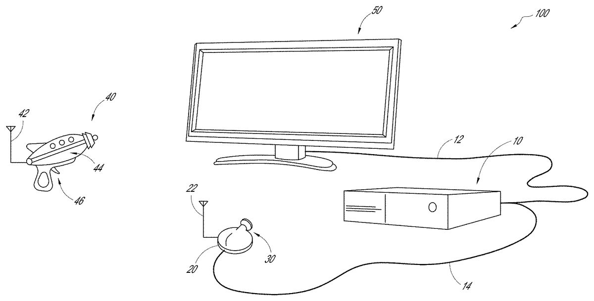
DETAILED DESCRIPTION FIG. 1shows one embodiment of a video gaming system100. The system100can include a console10, a light locating camera20that utilizes an optical filter30, and a light targeting peripheral (LTP)40(e.g., a light gun). Advantageously, the system100can be used with any size or type of display screen, including any type of television (e.g., LCD, LED, CRT, Plasma, etc.), computer monitor, display area (e.g., a projector screen, a wall area) that can display a video game image (e.g., projected onto the display area by a projector), or a display area that does not display a video game image (e.g., a poster used for calibration), where video game images are provided by a separate device (e.g., a virtual reality device, such as a head mounted display worn by the user), for example. The LTP40can direct non-visible light (e.g., an infrared (IR) light, ultraviolet (UV) light, etc.) onto a display screen50, and the location of the light on the display screen50can be located by the camera20, as discussed in more detail below. The console10can communicate with the display screen50(e.g., via a cable12), and the camera20can communicate with the console10(e.g., via a cable14). The console10can operate the video game and communicate with the display screen50to display images from the video game and provide audio effects associated with the video game. In some embodiments, one or more of the console10, camera20and LTP40can communicate wirelessly (e.g., via an RF link). In the illustrated embodiment, the LTP40can communicate wirelessly with the camera20, such as via an RF link. In another embodiment, the LTP40can additionally, or alternatively, communicates with the console10. For example, if the image processing is at least partially performed by software in the console10, the LTP40can communicate with the console10. The LTP40can have a wireless transmitter42to transmit data to one or both of the console10and the ...
DETAILED DESCRIPTION
FIG. 1shows one embodiment of a video gaming system100. The system100can include a console10, a light locating camera20that utilizes an optical filter30, and a light targeting peripheral (LTP)40(e.g., a light gun). Advantageously, the system100can be used with any size or type of display screen, including any type of television (e.g., LCD, LED, CRT, Plasma, etc.), computer monitor, display area (e.g., a projector screen, a wall area) that can display a video game image (e.g., projected onto the display area by a projector), or a display area that does not display a video game image (e.g., a poster used for calibration), where video game images are provided by a separate device (e.g., a virtual reality device, such as a head mounted display worn by the user), for example.
The LTP40can direct non-visible light (e.g., an infrared (IR) light, ultraviolet (UV) light, etc.) onto a display screen50, and the location of the light on the display screen50can be located by the camera20, as discussed in more detail below. The console10can communicate with the display screen50(e.g., via a cable12), and the camera20can communicate with the console10(e.g., via a cable14). The console10can operate the video game and communicate with the display screen50to display images from the video game and provide audio effects associated with the video game. In some embodiments, one or more of the console10, camera20and LTP40can communicate wirelessly (e.g., via an RF link).
In the illustrated embodiment, the LTP40can communicate wirelessly with the camera20, such as via an RF link. In another embodiment, the LTP40can additionally, or alternatively, communicates with the console10. For example, if the image processing is at least partially performed by software in the console10, the LTP40can communicate with the console10. The LTP40can have a wireless transmitter42to transmit data to one or both of the console10and the camera20, which can have a wireless receiver22, as discussed further below. Optionally, the LTP40can also have a wireless receiver to receive data from one or both of the console10and the camera20. In still another embodiment, the LTP40can communicate with one or both of the camera20and console10via a cable. The LTP40can have a light source44, which in one embodiment can be an infrared laser, where the IR laser can have optics to collimate and focus the laser so that the laser is straight, and where the size of the IR light dot from the laser has the same size regardless of the distance of the LTP40from the display screen50. In another embodiment, the LTP40can have an infrared LED as the light source44, with optics to focus the IR light from the LED. The size of the IR light dot will vary with the distance of the LTP40is from the display screen50(e.g., the IR light dot will be larger the farther the LTP40is from the display screen50). However, in other embodiments, the light source44of the LTP40can use other forms of non-visible light (e.g., ultraviolet light).
The LTP40can optionally be customizable. In one embodiment, the LTP40can be a passive device and include a non-visible light emitter (e.g., an IR light emitter) as the light source44and a trigger46. In one embodiment, actuation of the trigger46can break or switch off the non-visible light that is otherwise continuously emitted. In another embodiment, actuation of the trigger46does not break or switch off the non-visible light but communicates with the camera20and/or console10when the trigger46is actuated. In still another embodiment, the actuation of the trigger46can turn on the non-visible light momentarily, where the non-visible light is otherwise switched off, as described further below. If the LTP40is a wireless device, it can also include one or more batteries (not shown) and the wireless transmitter42. Where the LTP40is a passive device, it does not receive any data from the camera20.
In another embodiment, the LTP40can be an active device. In this embodiment, in addition to having the features described above for a passive device, the LTP40can include a receiver (e.g. wireless receiver) and circuitry (e.g., integrated circuit or IC) that allows it to have additional functionality. For example, the LTP40can receive data from the camera20that allows it to control aspects of the video game itself.
In another embodiment, the LTP40can include additional control inputs in addition to the trigger46that allow the LTP40to provide additional inputs to the video game, such as when the LTP40is an active device as described above. For example, the LTP40can include one or more of a D-pad, one or more input buttons, and an analog joystick.
In another embodiment, the LTP40can have one or more sensors, such as accelerometers, magnetometers, gyroscopes, that can be used in inertial tracking of the LTP40by tracking software of the system100. Said inertial tracking can facilitate the determination of the location of the non-visible light dot when the trigger is actuated (e.g., where the non-visible light is continually emitted and therefore continually tracked by the tracking software) by providing the tracking software with additional information about the direction of movement and/or orientation of the LTP40before the trigger46was actuated.
In another embodiment, the LTP40can have one or more expansion ports that can receive a controller to provide additional control in the video game. In such an embodiment, the LTP40can operate in tandem with the controller to provide a user with the ability to control more aspects of the video game than if the controller was not coupled to the LTP40.
The camera20can be positioned in any location that allows it to view or “look” at the display screen50(e.g., at a location below, above, to the left of, to the right of, close to, or far from the display screen50). Moreover, the camera20can be supported on any suitable surface, such as the floor, on a table, a counter, etc. The camera20can be mounted in any suitable manner. In one embodiment, the camera20can have a clamp that allows it to mount, for example, to a table (e.g., coffee table) or chair. In another embodiment, the camera20can have vacuum mount system (e.g., one or more vacuum cups or suction cups) that can removably mount the camera20to a support surface (such as a table surface, floor, etc.) to generally fix the location of the camera20. In still another embodiment, the camera20can have one or more pads (friction pads) on a bottom surface of the camera20to generally fix the location of the camera20. In one embodiment, the camera20can have a low profile that inhibits unintended movement of the camera20, for example, when bumped by a user. Optionally, the camera20can be dome shaped. In one embodiment, the camera20can have an accelerometer or other type of orientation sensor (e.g., magnetometer) that can provide information on the orientation of the camera20, which can be used by the software (e.g., calibration software or tracking software, as described further below) to ensure that the location of a non-visible light when the trigger46is actuated is correctly translated onto the display screen50.
With continued reference toFIG. 1, the camera20can have an optical filter30that filters out visible light but allows the camera20to view non-visible light, such as a low-pass IR optical filter, where the filter30is selectively applied to filter out visible light. In one embodiment, the optical filter30can resemble a piece of black plastic.FIG. 2Ashows an embodiment of the camera20with the optical filter30positioned in front of the lens23of the camera20to filter out visible light while allowing non-visible light (e.g., IR light) to pass through the lens23of the camera20.FIG. 2Bshows the camera20ofFIG. 2A, where the optical filter30is positioned out of the way of the lens23to allow visible light to pass through the lens23of the camera20.
In one embodiment, the filter30is a switchable or removable filter30that can be selectively positioned in front of the lens23of the camera20. For example, in one embodiment, the optical filter30can be positioned mechanically in front of the lens23of the camera20and moved out of the way from in front of the lens23of the camera20, such as with a stepper motor. However, other suitable mechanisms can be used to position the optical filter30in front of the lens23of the camera20as well as move it out of the way of the lens23of the camera20, such as a sliding mechanism. In still another embodiment, the optical filter30can be manually positioned in front of the lens23of the camera20(e.g., by a user) as well as removed from in front of the lens23. In another embodiment, the camera20can have an electronically switchable optical filter (e.g., night mode), as opposed to a physical optical filter, that can be selectively operated to filter out visible light while allowing non-visible light (e.g., IR light) to pass through the lens23of the camera20. In some embodiments, the camera20can be a wide bandwidth camera, where the IR blocking filter has been removed so that the camera20can view IR through visible light. In one embodiment, the camera20is a Raspberry Pi Noir IR camera.
FIG. 2Cshows one embodiment of an electronics diagram for the camera20. The camera20can include an optical filter30and an actuator32that selectively positions the filter30in front of the lens23to filter out visible light. Optionally, the light that passes through the lens23can be processed by an image processing circuit24in the camera20. In another embodiment, the camera20can exclude the image processing circuit and such circuit can be in the console10. The camera20can also include a communication module, which can be connected to the wireless receiver22and the cable14that connects the camera20to the console10. The camera20can also have control circuitry27for controlling the operation of the camera20, which can optionally include one or more sensors (e.g., accelerometer, magnetometer) and a memory28. In one embodiment, the camera20received power from an outside source via a power module29and cable. In another embodiment, the camera20can be powered by one or more batteries (not shown).
Calibration
Prior to use of the system100, the position of the camera20is calibrated relative to the display screen50.FIG. 3shows a flowchart of a calibration method200for the camera20. The optical filter30is removed210from the camera20(or the optical filter is switched off where the camera20has an electronically switchable optical filter) so that the camera20can see visible light. A calibration image is displayed230on the display screen50(e.g., by the console10). Image recognition software processes250the visible light video feed (e.g., continually reads the video output) from the camera20to find the calibration image. In one embodiment the image processing is at least partially performed by the camera20(via the image processing circuit24, as described above). In another embodiment, the image processing is at least partially performed by the console10. Once the calibration image is found by the software, the software calculates270camera coordinates that represent the corners of the display screen50in the field of view of the camera20, at which point the calibration of the camera20is completed. In some embodiments, where the camera20has an extra wide angle lens that distorts the image and where the display screen50appears curved, the image recognition software utilizes additional algorithms to undistort the image.
With respect to step230, various different images can be used in the calibration method200. In one embodiment, the calibration image can be a QR code. In another embodiment, the calibration image can be a plain screen image that cycles through a known sequence of colors on the display screen50(e.g., all red, all blue, all green, etc.), where the image recognition software can process the image and look for pixels in the live feed from the camera20that mimics the sequence of the calibration image.
FIG. 3Ashows one embodiment of a calibration image230A that can be used in step230of the calibration method200, where the calibration image230A includes nine markers232that are displayed on the display screen50. The image recognition software can process250the calibration image using a Harris Corner Detection algorithm. In another embodiment, the image recognition software can process250the calibration image using other suitable algorithms, such as a Features from Accelerated Segment Test (FAST) algorithm. Further details on the FAST algorithm can be found in the following articles, all of which are incorporated by reference: Edward Rosten et al.,Fusing Points and Lines for High Performance Tracking, IEEE International Conference on Computer Vision, October 2005; Edward Rosten et al.,Machine Learning for High-speed Corner Detection, European Conference on Computer Vision, May 2006; and Edward Rosten et al.,FASTER and Better: A Machine Learning Approach to Corner Detection, IEEE Trans. Pattern Analysis and Machine Intelligence, 2010.
The Harris Corner Detection algorithm returns a numerical value for each pixel in the camera image representative of a likelihood of the pixel being in a corner in the image. The algorithm filters out any pixel below a threshold value and generates a list of points (x, y coordinates) within the camera image that represent potential corners. The list of points are processed and grouped into clusters. For example, each point is processed to determine if it is within a distance threshold from any other point previously processed within an existing cluster; if the point is within the threshold it is added to the cluster. If said point is not within the threshold from another point, a new cluster is started with said point. This process is repeated until all points are processed. The center of each cluster is then calculated, which can be defined as the average coordinate of all the points in the cluster, and the radius of each cluster is also calculated, which is the furthest distance any of the points in the cluster is from the center of the cluster. Clusters having less than a predetermined number of points (e.g., less than 2 points) are rejected or filtered out.
FIG. 3Bshows a sub-step230B of the processing step250of the calibration process200with the calibration image on the display screen50, where all the detected clusters are represented by a circle and an identification number. As shown inFIG. 3B, the software has detected most of the reference marks, but there may be a few that are misidentified (e.g., no.7inFIG. 3B).
FIG. 3Cshows a sub-step230C of the processing step250in the calibration process200with the calibration image on the display screen50. The image recognition software determines if the clusters represent a screen by using the known relationship of the reference marks in the calibration image to each other. Each cluster in the list of clusters is evaluated as an “assumed” center point of the display screen50by determining if it meets the following set of rules. The image recognition software looks for pairs of clusters that can be connected by a line234that passes in close proximity to the center point of the “assumed” center point, and where the end points of such a line are approximately at the center of another line defined by another pair of clusters. InFIG. 3C, the line from cluster1to cluster7passes through the “assumed” center point (at cluster4) and the ends of said line are approximately at the center of the lines that connect clusters0to2and clusters6to8. Similarly, the line234that passes from cluster3to5passes through the “assumed” center point (at cluster4) and the ends of said line are approximately at the center of the lines that connect clusters2to8and that connect clusters0to6. The end point lines are evaluated to ensure they form a closed rectangle around the center point, and diagonal lines from the intersection of the four end point lines are evaluated to confirm the lines pass through the “assumed” center point. Additionally, angles between the four lines (e.g., between the line from cluster0to2, and line from cluster2to8) are evaluated to determine if the angle meets a threshold value (e.g. around 75 degrees). Because the camera20may be askew to the display screen50, the angle between the lines may not be approximately 90 degrees. Once the image recognition software has confirmed the “assumed” center point of the display screen50is the center point of the display screen50, the software determines270the coordinates of the four corners of the display screen50within the field of view of the camera20and the calibration is complete (e.g., P1-P4inFIG. 5B).
In another embodiment of the calibration method200, the calibration image, such as the calibration image230A inFIG. 3A, can be flashed on in one frame on the display screen50(e.g., by the console10) and turned off in the next frame on the display screen50. For example, in one embodiment the calibration image230A can be flashed on for 100 ms and turned off for 100 ms. However, in other embodiments, the time the calibration image230A is on and off can vary (e.g., can be about 150 ms). In the illustrated embodiment, the calibration image230A has nine markers. However, in other embodiments the calibration image230A can have a different number of markers (e.g., fewer markers, more markers). In one embodiment, the calibration image230A can have only four markers at the corners.
Image recognition software can process250the feed from the camera20frame by frame and perform frame subtraction to identify the changes in what is shown in the display screen50(e.g., identify changes on the display screen when the calibration image230A is turned on and off). In one embodiment, the camera20can operate at about 90 frames per second; however, in other embodiments, the camera20can operate at a larger or smaller number of frames per second. Where the flashed frames of the calibration image23A are not synchronized with the camera frames, the image processing software can use an algorithm, including an accumulator or counter, to account for the calibration image flashing at a slower rate than the camera operation, in order to perform the frame subtraction step and identify the calibration image. In one embodiment, the software compares a camera frame with a previous frame (e.g., a frame from 10-15 previous frames) that is not the immediately previous frame. In another embodiment, the software compares a camera frame with the immediately previous frame.
Due to the flashing of the calibration image230A on the display screen50, the frame subtraction process results in the background detail being removed (e.g., background detail that may be interpreted as false corners) and leaving only the calibration markers in a black screen (not shown), as shown inFIG. 3D. In some embodiments, the image calibration software can look for the flashing calibration image over a number of frames to identify the markers in the calibration image as reliable markers. The image recognition software can then associate the markers with the corners of the screen and the software determines270the coordinates of the four corners on the display screen50within the field of view of the camera20(e.g., connects the markers with lines to define the corners of the display screen50within the field of view of the camera20), as shown inFIG. 3E. The flashing of the calibration image and use of frame subtraction can advantageously simplify and speed-up the calibration process.
In one embodiment, the calibration method200can be performed every time the system100is turned on, prior to the user playing a game. In another embodiment, the calibration method200can be performed at a predetermined time (e.g., once a day, once every other day, once every week, etc.).
Recalibration
FIG. 4shows one embodiment of a recalibration method300, which can be performed after the calibration method200has been completed (e.g., while in play mode, discussed further below). If the camera20position moves (e.g., as a result of a player bumping into the camera), the camera20can be recalibrated relative to the display screen50. With continued reference toFIG. 4, if motion of the camera20is sensed310(e.g., with one or more sensors in the camera20, such as an accelerometer), the software determines320if the sensed motion is above a predetermined threshold (e.g., above a predetermined force magnitude). In one embodiment, the one or more sensors in the camera20that sense whether the camera20has been moved can be the same sensors used to determine the orientation of the camera20, as discussed above; in another embodiment, the sensors that sense movement of the camera20to determine if recalibration should be performed can be separate from the one or more sensors that sense the orientation of the camera20. If the sensed movement is above the threshold, then the calibration method200is performed again (seeFIG. 3). In one embodiment, if the sensed motion is above the predetermined threshold, the system100may automatically being the recalibration of the camera20. In another embodiment, the system100can provide feedback to the user (e.g., visual and/or audio feedback) that the camera20needs to be recalibrated, at which point the video game is paused and the camera20is recalibrated. If the sensed motion310is not above the threshold, the software determines that recalibration is not needed.
Play Mode—Tracking Non-Visible Light
FIG. 5shows a flowchart of a method of tracking the non-visible light (e.g., IR light) from the LTP40when the system100is in play mode (shown inFIG. 5A). Once calibration of the camera20is completed, the optical filter (such as optical filter30) is positioned410in front of the lens23of the camera20to filter out visible light while allowing non-visible light to pass through the lens23of the camera20.
The tracking software searches the feed from the camera20for non-visible light (e.g., IR light). As shown inFIG. 5B, there may be multiple sources of non-visible light, such as background IR light on a wall IR2, IR light on an LED TV IR3, IR reflection on the display screen50IR4, so the software determines430which source is most likely to be the non-visible light IR1from the LTP40. In one embodiment, the software determines which source in the video feed is the non-visible light IR1from the LTP40by filtering out intensity values below a predetermined threshold value (e.g., to filter out background light). In another embodiment, the software additionally, or alternatively, ignores (filters out) light sources that aren't round (or less dense, as discussed further below). For example, the software searches for a group of pixels that form a dot (e.g., generally circular shape) with the highest concentration or density of pixels, while considering the intensity values. In still another embodiment, the software ignores (filters out) light sources that are outside the quadrangle defined by the corners of the display screen (P1-P4inFIG. 5B) that are in the field of view of the camera20. However, other suitable techniques for identifying the non-visible light IR1from the LTP40can be used.
In another embodiment, the image processing software compares a frame (seeFIG. 5C), in which the non-visible light IR1from the LTP40has not been actuated, with the camera frame inFIG. 5B, in which the non-visible light IR1from the LTP40has been actuated, and uses a frame subtraction algorithm, as discussed above, to filter out sources of non-visible light that are not associated with the LTP40, resulting in the image onFIG. 5D, where non-visible light from other than the LTP40has been filtered out. In some embodiments, the image processing software can further use an algorithm to confirm that the remaining non-visible light on the screen50corresponds to the light from the LTP40. For example, as discussed above, the software can search for a group of pixels that form a dot (e.g., generally circular shape) with the highest concentration or density of pixels, while considering the intensity values.
Once the location of the non-visible light IR1from the LTP40is detected (e.g., at location tx, tyinFIG. 5BorFIG. 5D), the tracking software expresses450the position of the non-visible light dot IR1as a proportion of the quadrangle (P1-P4). In one embodiment, shown inFIG. 5E, this is done by projecting a line from one of the corners (e.g., P1) of the quadrangle through the detected location (tx, ty) of the non-visible light dot IR1(e.g., IR light dot), calculating where it intersects the opposite side of the quadrangle (P1-P4), and expressing said intersection on the opposite side of the quadrangle (P1-P4) as a proportion of the distance L2along said opposite side (e.g., Y1/Y2); this process of projecting a line from a corner through the detected location of the non-visible light dot and calculating the intersection of the line on an opposite side of the quadrangle and expressing it as a proportional distance along said opposite side can be repeated for one or more other corners of the quadrangle (P1-P4).
As shown inFIG. 5F, the tracking software then maps470said proportional distances (e.g., L2*Y1/Y2, L1*X1/X2inFIG. 5E) on the sides of the quadrangle (P1-P4) onto the display screen50to identify intersection points along corresponding borders of the display screen50(e.g., X1/X2and Y1/Y2inFIG. 5Eis equal to X3/X4and Y3/Y4inFIG. 5F, respectively). Lines are then calculated490from said intersection points to one or more corners (e.g., P1, P3) of the display screen50opposite the intersection location, and the intersection point of all the lines corresponds to the location trx, try) of the non-visible light dot (e.g., IR light dot) on the display screen50.
In the tracking process described above, only two lines need to be drawn from corners of the quadrangle (P1-P4) through the detected location (tx, ty) of the non-visible light dot and onto opposite sides of the quadrangle, which can then be translated to the display screen50as discussed above to translate the camera view to the display screen50or “game space”. However, use of four lines (one from each of the corners of the quadrangle) that intersect the detected non-visible light dot location can improve the accuracy of providing the non-visible light dot location on the display screen50and provides for error redundancy.
In one embodiment, the non-visible light (e.g., IR light) is continually projected by the LTP40, and the software is constantly tracking the non-visible light dot, but can in one embodiment only record its position once the trigger46on the LTP40is actuated. In another embodiment, the non-visible light is continually projected by the LTP40, but the light is switched off when the trigger46is actuated; in this embodiment, the tracking software searches the feed from the camera20for the location where the non-visible light dot is missing, and translates this location to the display screen50, as discussed above. Advantageously, this method of continually projecting the non-visible light and recording only when the trigger46is actuated provides a relatively fast system response (e.g., minimum latency) from the actuation of the trigger46to the video game providing feedback to the user (e.g., visual and/or audio feedback). However, the location of the non-visible light dot that is recorded corresponds to a location where the LTP40was pointed a fraction of a second prior, and one or more batteries of the LTP40may drain more quickly (e.g., where the LTP40is wireless) since the non-visible light would be constantly projected.
In another embodiment, the non-visible light is only projected by the LTP40when the trigger46is actuated. The software then searches the feed from the camera20to identify the non-visible light dot, as discussed above. Advantageously, this method results in increased accuracy of the actual position when the trigger46is actuated, and the one or more batteries of the LTP40(e.g., where the LTP40is wireless) may drain more slowly since the light is only projected when the trigger46is actuated. However, due to the latency in reviewing the feed from the camera20, it may take several milliseconds for the non-visible light dot to be identified in the camera feed and communicated to the console10, which may increase the latency for the user to receive feedback (e.g., visual and/or audio feedback) following the actuation of the trigger46.
FIG. 6shows a schematic diagram of the electronics in the LTP40. The LTP40can have a light source or emitter44, as discussed above, which can be electrically connected to control circuitry41. The control circuitry41can be electrically connected to a communication module43, which includes a wireless transmitter42, as discussed above. The LTP40can also have a switch47that is actuated by the trigger46and that communicates with the control circuitry41to indicate when the trigger46has been actuated. The LTP40can also have one or more batteries48that can power the electronics, including the control circuitry41, communication module43and switch47. In one embodiment, as discussed above, the LTP40can have one or more sensors, which can be part of the control circuitry41.
ThoughFIG. 1shows a single LTP40, one of skill in the art will recognize that more than one LTP40can be utilized while playing the video game (e.g., two LTPs40, four LTPs40), depending on the number of players, as shown inFIG. 7. As discussed above, the LTP40can communicate with one or both of the camera20and console10via an RF link. To accommodate multiple users during a video game, the system100can utilize a time division multiplexing method so that the multiple LTPs40are not all allowed to be actuated at the same time.
The console10can optionally have one or more processors, a communication interface, a main memory, a ROM and a storage device, which can be connected to a bus.
While certain embodiments of the inventions have been described, these embodiments have been presented by way of example only, and are not intended to limit the scope of the disclosure. Indeed, the novel methods and systems described herein may be embodied in a variety of other forms. Furthermore, various omissions, substitutions and changes in the systems and methods described herein may be made without departing from the spirit of the disclosure. The accompanying claims and their equivalents are intended to cover such forms or modifications as would fall within the scope and spirit of the disclosure. Accordingly, the scope of the present inventions is defined only by reference to the appended claims.
Features, materials, characteristics, or groups described in conjunction with a particular aspect, embodiment, or example are to be understood to be applicable to any other aspect, embodiment or example described in this section or elsewhere in this specification unless incompatible therewith. All of the features disclosed in this specification (including any accompanying claims, abstract and drawings), and/or all of the steps of any method or process so disclosed, may be combined in any combination, except combinations where at least some of such features and/or steps are mutually exclusive. The protection is not restricted to the details of any foregoing embodiments. The protection extends to any novel one, or any novel combination, of the features disclosed in this specification (including any accompanying claims, abstract and drawings), or to any novel one, or any novel combination, of the steps of any method or process so disclosed.
Furthermore, certain features that are described in this disclosure in the context of separate implementations can also be implemented in combination in a single implementation. Conversely, various features that are described in the context of a single implementation can also be implemented in multiple implementations separately or in any suitable subcombination. Moreover, although features may be described above as acting in certain combinations, one or more features from a claimed combination can, in some cases, be excised from the combination, and the combination may be claimed as a subcombination or variation of a sub combination.
Moreover, while operations may be depicted in the drawings or described in the specification in a particular order, such operations need not be performed in the particular order shown or in sequential order, or that all operations be performed, to achieve desirable results. Other operations that are not depicted or described can be incorporated in the example methods and processes. For example, one or more additional operations can be performed before, after, simultaneously, or between any of the described operations. Further, the operations may be rearranged or reordered in other implementations. Those skilled in the art will appreciate that in some embodiments, the actual steps taken in the processes illustrated and/or disclosed may differ from those shown in the figures. Depending on the embodiment, certain of the steps described above may be removed, others may be added. Furthermore, the features and attributes of the specific embodiments disclosed above may be combined in different ways to form additional embodiments, all of which fall within the scope of the present disclosure. Also, the separation of various system components in the implementations described above should not be understood as requiring such separation in all implementations, and it should be understood that the described components and systems can generally be integrated together in a single product or packaged into multiple products.
For purposes of this disclosure, certain aspects, advantages, and novel features are described herein. Not necessarily all such advantages may be achieved in accordance with any particular embodiment. Thus, for example, those skilled in the art will recognize that the disclosure may be embodied or carried out in a manner that achieves one advantage or a group of advantages as taught herein without necessarily achieving other advantages as may be taught or suggested herein.
Conditional language, such as “can,” “could,” “might,” or “may,” unless specifically stated otherwise, or otherwise understood within the context as used, is generally intended to convey that certain embodiments include, while other embodiments do not include, certain features, elements, and/or steps. Thus, such conditional language is not generally intended to imply that features, elements, and/or steps are in any way required for one or more embodiments or that one or more embodiments necessarily include logic for deciding, with or without user input or prompting, whether these features, elements, and/or steps are included or are to be performed in any particular embodiment.
Conjunctive language such as the phrase “at least one of X, Y, and Z,” unless specifically stated otherwise, is otherwise understood with the context as used in general to convey that an item, term, etc. may be either X, Y, or Z. Thus, such conjunctive language is not generally intended to imply that certain embodiments require the presence of at least one of X, at least one of Y, and at least one of Z.
Language of degree used herein, such as the terms “approximately,” “about,” “generally,” and “substantially” as used herein represent a value, amount, or characteristic close to the stated value, amount, or characteristic that still performs a desired function or achieves a desired result. For example, the terms “approximately”, “about”, “generally,” and “substantially” may refer to an amount that is within less than 10% of, within less than 5% of, within less than 1% of, within less than 0.1% of, and within less than 0.01% of the stated amount. As another example, in certain embodiments, the terms “generally parallel” and “substantially parallel” refer to a value, amount, or characteristic that departs from exactly parallel by less than or equal to 15 degrees, 10 degrees, 5 degrees, 3 degrees, 1 degree, or 0.1 degree.
The scope of the present disclosure is not intended to be limited by the specific disclosures of preferred embodiments in this section or elsewhere in this specification, and may be defined by claims as presented in this section or elsewhere in this specification or as presented in the future. The language of the claims is to be interpreted broadly based on the language employed in the claims and not limited to the examples described in the present specification or during the prosecution of the application, which examples are to be construed as non-exclusive.
Claims
- A method of operating a video game system, comprising: applying an optical filter in a field of view of a camera to filter out visible light and allow the camera to view non-visible light directed at a display screen positioned within the field of view of the camera;processing a digital video output feed from the camera with a computer processor to identify a location of a non-visible light dot within the field of view of the camera that is projected onto the display screen by a light targeting peripheral unit;calculating the location of the non-visible light dot within the field of view of the camera as a proportion of one or more dimensions of the field of view of the camera;translating the location of the non-visible light dot within the field of view of the camera onto a location on the display screen;and initiating a recalibration of the camera to recalculate a boundary of the display screen in the field of view of the camera if a motion of the camera above a threshold amount is sensed with a motion sensor.
- The method of claim 1 , wherein applying the optical filter includes mechanically positioning the optical filter in the field of view of the camera.
- The method of claim 1 , wherein applying the optical filter includes turning on an electronically switchable optical filter.
- The method of claim 1 , wherein processing the digital video feed from the camera includes continuously processing the video output feed.
- The method of claim 1 , wherein said processing is performed at least in part by the camera.
- The method of claim 1 , wherein said processing is performed at least in part by a console of the video game system.
- The method of claim 1 , wherein translating the location of the non-visible light dot within the field of view of the camera onto the location on the display screen includes applying the proportion of said one or more dimensions of the field of view of the camera to corresponding dimensions on the display screen.
- The method of claim 1 , wherein translating includes translating the location of the non-visible light dot onto the location on the display screen irrespective of the size of the display screen.
- The method of claim 8 , wherein the display screen is a television.
- The method of claim 1 , wherein the non-visible light dot is an infrared light dot.
- The method of claim 1 , wherein processing includes searching in the digital video output feed the location of the non-visible light dot continually projected by the light targeting peripheral unit, and recording the position of the non-visible light dot upon actuation of an actuator of the light targeting peripheral unit.
- The method of claim 1 , wherein processing includes searching the digital video output feed from the camera for the non-visible light dot that is projected by the light targeting peripheral unit onto the display screen upon actuation of an actuator of the light targeting peripheral unit.
- The method of claim 1 , wherein processing the video output feed from the camera with a computer processor to identify a location of a non-visible light dot within the field of view of the camera includes filtering out intensity values of non-visible light below a predetermined threshold value.
- The method of claim 1 , wherein processing the digital video output feed from the camera with a computer processor to identify a location of a non-visible light dot within the field of view of the camera includes filtering out non-visible light having a density of pixels below a threshold value.
- A method of operating a video game system, comprising: mechanically positioning an optical filter in a field of view of a camera to filter out visible light and allow the camera to view non-visible light directed at a display screen positioned within the field of view of the camera;searching a digital video output feed from the camera with a computer processor to identify a location of a non-visible light dot within the field of view of the camera that is projected onto the display screen by a light targeting peripheral unit;calculating the location of the non-visible light dot within the field of view of the camera as a proportion of one or more dimensions of the field of view of the camera;translating the location of the non-visible light dot within the field of view of the camera onto a location on the display screen;and initiating a recalibration of the camera to recalculate a boundary of the display screen in the field of view of the camera if a motion of the camera above a threshold amount is sensed with a motion sensor.
- The method of claim 15 , wherein the display screen is a television.
- The method of claim 15 , wherein the non-visible light dot is an infrared light dot.
- The method of claim 15 , wherein the non-visible light dot is continually projected by the light targeting peripheral unit onto the display screen and searching includes tracking in the digital video output feed the location of the non-visible light dot and recording the position of the non-visible light dot upon actuation of an actuator of the light targeting peripheral unit.
- The method of claim 15 , wherein the non-visible light dot is projected by the light targeting peripheral unit onto the display screen only upon actuation of the trigger, and searching includes searching in the digital video output feed the location of the non-visible light dot and recording the position of the non-visible light dot upon actuation of the actuator of the light targeting peripheral unit.
- A method of operating a video game system, comprising: positioning an optical filter in a field of view of a camera to filter out visible light and allow the camera to view non-visible light directed at a display screen positioned within the field of view of the camera;searching a digital video output feed from the camera with a computer processor to identify a location within the field of view of the camera where a non-visible light dot is absent upon actuation of an actuator of a light targeting peripheral that projects non-visible light onto the display screen;calculating the location within the field of view of the camera where the non-visible light dot is missing as a proportion of dimensions of the field of view of the camera;translating the location of the absence of the non-visible light dot within the field of view of the camera onto a location on the display screen by applying the proportion of said dimensions of the field of view of the camera to corresponding dimensions on the display screen;and initiating a recalibration of the camera to recalculate a boundary of the display screen in the field of view of the camera if a motion of the camera above a threshold amount is sensed with a motion sensor.
Disclaimer: Data collected from the USPTO and may be malformed, incomplete, and/or otherwise inaccurate.