U.S. Pat. No. 10,459,599
METHOD FOR MOVING IN VIRTUAL SPACE AND INFORMATION PROCESSING APPARATUS FOR EXECUTING THE METHOD
AssigneeCOLOPL, INC.
Issue DateFebruary 26, 2018
Illustrative Figure
Abstract
A method includes defining a virtual space. The virtual space includes a viewpoint associated with a first user, a first object, and a map object. At least one location option is associated with the map object. The method further includes defining a visual field based on a position of the viewpoint in the virtual space. The method further includes generating a visual-field image based on the visual field. The method further includes receiving a selection of any location option of the at least one location option by the first user. The method further includes moving the viewpoint to the selected location option. The method further includes updating the visual field based on a position of the selected viewpoint in the virtual space.
Description
DETAILED DESCRIPTION Now, with reference to the drawings, at least one embodiment of this disclosure is described. In the following description, like components are denoted by like reference symbols. The same applies to the names and functions of those components. Therefore, detailed description of those components is not repeated. Now, with reference to the drawings, embodiments of this technical idea are described in detail. In the following description, like components are denoted by like reference symbols. The same applies to the names and functions of those components. Therefore, detailed description of those components is not repeated. In one or more embodiments described in this disclosure, components of respective embodiments can be combined with each other, and the combination also serves as a part of the embodiments described in this disclosure. [Configuration of HMD System] With reference toFIG. 1, a configuration of a head-mounted device (HMD) system100is described.FIG. 1is a diagram of a system100including a head-mounted display (HMD) according to at least one embodiment of this disclosure. The system100is usable for household use or for professional use. The system100includes a server600, HMD sets110A,110B,110C, and110D, an external device700, and a network2. Each of the HMD sets110A,110B,110C, and110D is capable of independently communicating to/from the server600or the external device700via the network2. In some instances, the HMD sets110A,110B,110C, and110D are also collectively referred to as “HMD set110”. The number of HMD sets110constructing the HMD system100is not limited to four, but may be three or less, or five or more. The HMD set110includes an HMD120, a computer200, an HMD sensor410, a display430, and a controller300. The HMD120includes a monitor130, an eye gaze sensor140, a first camera150, a second camera160, a microphone170, and a speaker180. In at least one embodiment, the controller300includes a motion sensor420. In at least one aspect, the computer200is connected to the network2, ...
DETAILED DESCRIPTION
Now, with reference to the drawings, at least one embodiment of this disclosure is described. In the following description, like components are denoted by like reference symbols. The same applies to the names and functions of those components. Therefore, detailed description of those components is not repeated.
Now, with reference to the drawings, embodiments of this technical idea are described in detail. In the following description, like components are denoted by like reference symbols. The same applies to the names and functions of those components. Therefore, detailed description of those components is not repeated. In one or more embodiments described in this disclosure, components of respective embodiments can be combined with each other, and the combination also serves as a part of the embodiments described in this disclosure.
[Configuration of HMD System]
With reference toFIG. 1, a configuration of a head-mounted device (HMD) system100is described.FIG. 1is a diagram of a system100including a head-mounted display (HMD) according to at least one embodiment of this disclosure. The system100is usable for household use or for professional use.
The system100includes a server600, HMD sets110A,110B,110C, and110D, an external device700, and a network2. Each of the HMD sets110A,110B,110C, and110D is capable of independently communicating to/from the server600or the external device700via the network2. In some instances, the HMD sets110A,110B,110C, and110D are also collectively referred to as “HMD set110”. The number of HMD sets110constructing the HMD system100is not limited to four, but may be three or less, or five or more. The HMD set110includes an HMD120, a computer200, an HMD sensor410, a display430, and a controller300. The HMD120includes a monitor130, an eye gaze sensor140, a first camera150, a second camera160, a microphone170, and a speaker180. In at least one embodiment, the controller300includes a motion sensor420.
In at least one aspect, the computer200is connected to the network2, for example, the Internet, and is able to communicate to/from the server600or other computers connected to the network2in a wired or wireless manner. Examples of the other computers include a computer of another HMD set110or the external device700. In at least one aspect, the HMD120includes a sensor190instead of the HMD sensor410. In at least one aspect, the HMD120includes both sensor190and the HMD sensor410.
The HMD120is wearable on a head of a user5to display a virtual space to the user5during operation. More specifically, in at least one embodiment, the HMD120displays each of a right-eye image and a left-eye image on the monitor130. Each eye of the user5is able to visually recognize a corresponding image from the right-eye image and the left-eye image so that the user5may recognize a three-dimensional image based on the parallax of both of the user's the eyes. In at least one embodiment, the HMD120includes any one of a so-called head-mounted display including a monitor or a head-mounted device capable of mounting a smartphone or other terminals including a monitor.
The monitor130is implemented as, for example, a non-transmissive display device. In at least one aspect, the monitor130is arranged on a main body of the HMD120so as to be positioned in front of both the eyes of the user5. Therefore, when the user5is able to visually recognize the three-dimensional image displayed by the monitor130, the user5is immersed in the virtual space. In at least one aspect, the virtual space includes, for example, a background, objects that are operable by the user5, or menu images that are selectable by the user5. In at least one aspect, the monitor130is implemented as a liquid crystal monitor or an organic electroluminescence (EL) monitor included in a so-called smartphone or other information display terminals.
In at least one aspect, the monitor130is implemented as a transmissive display device. In this case, the user5is able to see through the HMD120covering the eyes of the user5, for example, smartglasses. In at least one embodiment, the transmissive monitor130is configured as a temporarily non-transmissive display device through adjustment of a transmittance thereof. In at least one embodiment, the monitor130is configured to display a real space and a part of an image constructing the virtual space simultaneously. For example, in at least one embodiment, the monitor130displays an image of the real space captured by a camera mounted on the HMD120, or may enable recognition of the real space by setting the transmittance of a part the monitor130sufficiently high to permit the user5to see through the HMD120.
In at least one aspect, the monitor130includes a sub-monitor for displaying a right-eye image and a sub-monitor for displaying a left-eye image. In at least one aspect, the monitor130is configured to integrally display the right-eye image and the left-eye image. In this case, the monitor130includes a high-speed shutter. The high-speed shutter operates so as to alternately display the right-eye image to the right of the user5and the left-eye image to the left eye of the user5, so that only one of the user's5eyes is able to recognize the image at any single point in time.
In at least one aspect, the HMD120includes a plurality of light sources (not shown). Each light source is implemented by, for example, a light emitting diode (LED) configured to emit an infrared ray. The HMD sensor410has a position tracking function for detecting the motion of the HMD120. More specifically, the HMD sensor410reads a plurality of infrared rays emitted by the HMD120to detect the position and the inclination of the HMD120in the real space.
In at least one aspect, the HMD sensor410is implemented by a camera. In at least one aspect, the HMD sensor410uses image information of the HMD120output from the camera to execute image analysis processing, to thereby enable detection of the position and the inclination of the HMD120.
In at least one aspect, the HMD120includes the sensor190instead of, or in addition to, the HMD sensor410as a position detector. In at least one aspect, the HMD120uses the sensor190to detect the position and the inclination of the HMD120. For example, in at least one embodiment, when the sensor190is an angular velocity sensor, a geomagnetic sensor, or an acceleration sensor, the HMD120uses any or all of those sensors instead of (or in addition to) the HMD sensor410to detect the position and the inclination of the HMD120. As an example, when the sensor190is an angular velocity sensor, the angular velocity sensor detects over time the angular velocity about each of three axes of the HMD120in the real space. The HMD120calculates a temporal change of the angle about each of the three axes of the HMD120based on each angular velocity, and further calculates an inclination of the HMD120based on the temporal change of the angles.
The eye gaze sensor140detects a direction in which the lines of sight of the right eye and the left eye of the user5are directed. That is, the eye gaze sensor140detects the line of sight of the user5. The direction of the line of sight is detected by, for example, a known eye tracking function. The eye gaze sensor140is implemented by a sensor having the eye tracking function. In at least one aspect, the eye gaze sensor140includes a right-eye sensor and a left-eye sensor. In at least one embodiment, the eye gaze sensor140is, for example, a sensor configured to irradiate the right eye and the left eye of the user5with an infrared ray, and to receive reflection light from the cornea and the iris with respect to the irradiation light, to thereby detect a rotational angle of each of the user's5eyeballs. In at least one embodiment, the eye gaze sensor140detects the line of sight of the user5based on each detected rotational angle.
The first camera150photographs a lower part of a face of the user5. More specifically, the first camera150photographs, for example, the nose or mouth of the user5. The second camera160photographs, for example, the eyes and eyebrows of the user5. A side of a casing of the HMD120on the user5side is defined as an interior side of the HMD120, and a side of the casing of the HMD120on a side opposite to the user5side is defined as an exterior side of the HMD120. In at least one aspect, the first camera150is arranged on an exterior side of the HMD120, and the second camera160is arranged on an interior side of the HMD120. Images generated by the first camera150and the second camera160are input to the computer200. In at least one aspect, the first camera150and the second camera160are implemented as a single camera, and the face of the user5is photographed with this single camera.
The microphone170converts an utterance of the user5into a voice signal (electric signal) for output to the computer200. The speaker180converts the voice signal into a voice for output to the user5. In at least one embodiment, the speaker180converts other signals into audio information provided to the user5. In at least one aspect, the HMD120includes earphones in place of the speaker180.
The controller300is connected to the computer200through wired or wireless communication. The controller300receives input of a command from the user5to the computer200. In at least one aspect, the controller300is held by the user5. In at least one aspect, the controller300is mountable to the body or a part of the clothes of the user5. In at least one aspect, the controller300is configured to output at least any one of a vibration, a sound, or light based on the signal transmitted from the computer200. In at least one aspect, the controller300receives from the user5an operation for controlling the position and the motion of an object arranged in the virtual space.
In at least one aspect, the controller300includes a plurality of light sources. Each light source is implemented by, for example, an LED configured to emit an infrared ray. The HMD sensor410has a position tracking function. In this case, the HMD sensor410reads a plurality of infrared rays emitted by the controller300to detect the position and the inclination of the controller300in the real space. In at least one aspect, the HMD sensor410is implemented by a camera. In this case, the HMD sensor410uses image information of the controller300output from the camera to execute image analysis processing, to thereby enable detection of the position and the inclination of the controller300.
In at least one aspect, the motion sensor420is mountable on the hand of the user5to detect the motion of the hand of the user5. For example, the motion sensor420detects a rotational speed, a rotation angle, and the number of rotations of the hand. The detected signal is transmitted to the computer200. The motion sensor420is provided to, for example, the controller300. In at least one aspect, the motion sensor420is provided to, for example, the controller300capable of being held by the user5. In at least one aspect, to help prevent accidently release of the controller300in the real space, the controller300is mountable on an object like a glove-type object that does not easily fly away by being worn on a hand of the user5. In at least one aspect, a sensor that is not mountable on the user5detects the motion of the hand of the user5. For example, a signal of a camera that photographs the user5may be input to the computer200as a signal representing the motion of the user5. As at least one example, the motion sensor420and the computer200are connected to each other through wired or wireless communication. In the case of wireless communication, the communication mode is not particularly limited, and for example, Bluetooth (trademark) or other known communication methods are usable.
The display430displays an image similar to an image displayed on the monitor130. With this, a user other than the user5wearing the HMD120can also view an image similar to that of the user5. An image to be displayed on the display430is not required to be a three-dimensional image, but may be a right-eye image or a left-eye image. For example, a liquid crystal display or an organic EL monitor may be used as the display430.
In at least one embodiment, the server600transmits a program to the computer200. In at least one aspect, the server600communicates to/from another computer200for providing virtual reality to the HMD120used by another user. For example, when a plurality of users play a participatory game, for example, in an amusement facility, each computer200communicates to/from another computer200via the server600with a signal that is based on the motion of each user, to thereby enable the plurality of users to enjoy a common game in the same virtual space. Each computer200may communicate to/from another computer200with the signal that is based on the motion of each user without intervention of the server600.
The external device700is any suitable device as long as the external device700is capable of communicating to/from the computer200. The external device700is, for example, a device capable of communicating to/from the computer200via the network2, or is a device capable of directly communicating to/from the computer200by near field communication or wired communication. Peripheral devices such as a smart device, a personal computer (PC), or the computer200are usable as the external device700, in at least one embodiment, but the external device700is not limited thereto.
[Hardware Configuration of Computer]
With reference toFIG. 2, the computer200in at least one embodiment is described.FIG. 2is a block diagram of a hardware configuration of the computer200according to at least one embodiment. The computer200includes, a processor210, a memory220, a storage230, an input/output interface240, and a communication interface250. Each component is connected to a bus260. In at least one embodiment, at least one of the processor210, the memory220, the storage230, the input/output interface240or the communication interface250is part of a separate structure and communicates with other components of computer200through a communication path other than the bus260.
The processor210executes a series of commands included in a program stored in the memory220or the storage230based on a signal transmitted to the computer200or in response to a condition determined in advance. In at least one aspect, the processor210is implemented as a central processing unit (CPU), a graphics processing unit (GPU), a micro-processor unit (MPU), a field-programmable gate array (FPGA), or other devices.
The memory220temporarily stores programs and data. The programs are loaded from, for example, the storage230. The data includes data input to the computer200and data generated by the processor210. In at least one aspect, the memory220is implemented as a random access memory (RAM) or other volatile memories.
The storage230permanently stores programs and data. In at least one embodiment, the storage230stores programs and data for a period of time longer than the memory220, but not permanently. The storage230is implemented as, for example, a read-only memory (ROM), a hard disk device, a flash memory, or other non-volatile storage devices. The programs stored in the storage230include programs for providing a virtual space in the system100, simulation programs, game programs, user authentication programs, and programs for implementing communication to/from other computers200. The data stored in the storage230includes data and objects for defining the virtual space.
In at least one aspect, the storage230is implemented as a removable storage device like a memory card. In at least one aspect, a configuration that uses programs and data stored in an external storage device is used instead of the storage230built into the computer200. With such a configuration, for example, in a situation in which a plurality of HMD systems100are used, for example in an amusement facility, the programs and the data are collectively updated.
The input/output interface240allows communication of signals among the HMD120, the HMD sensor410, the motion sensor420, and the display430. The monitor130, the eye gaze sensor140, the first camera150, the second camera160, the microphone170, and the speaker180included in the HMD120may communicate to/from the computer200via the input/output interface240of the HMD120. In at least one aspect, the input/output interface240is implemented with use of a universal serial bus (USB), a digital visual interface (DVI), a high-definition multimedia interface (HDMI) (trademark), or other terminals. The input/output interface240is not limited to the specific examples described above.
In at least one aspect, the input/output interface240further communicates to/from the controller300. For example, the input/output interface240receives input of a signal output from the controller300and the motion sensor420. In at least one aspect, the input/output interface240transmits a command output from the processor210to the controller300. The command instructs the controller300to, for example, vibrate, output a sound, or emit light. When the controller300receives the command, the controller300executes any one of vibration, sound output, and light emission in accordance with the command.
The communication interface250is connected to the network2to communicate to/from other computers (e.g., server600) connected to the network2. In at least one aspect, the communication interface250is implemented as, for example, a local area network (LAN), other wired communication interfaces, wireless fidelity (Wi-Fi), Bluetooth®, near field communication (NFC), or other wireless communication interfaces. The communication interface250is not limited to the specific examples described above.
In at least one aspect, the processor210accesses the storage230and loads one or more programs stored in the storage230to the memory220to execute a series of commands included in the program. In at least one embodiment, the one or more programs includes an operating system of the computer200, an application program for providing a virtual space, and/or game software that is executable in the virtual space. The processor210transmits a signal for providing a virtual space to the HMD120via the input/output interface240. The HMD120displays a video on the monitor130based on the signal.
InFIG. 2, the computer200is outside of the HMD120, but in at least one aspect, the computer200is integral with the HMD120. As an example, a portable information communication terminal (e.g., smartphone) including the monitor130functions as the computer200in at least one embodiment.
In at least one embodiment, the computer200is used in common with a plurality of HMDs120. With such a configuration, for example, the computer200is able to provide the same virtual space to a plurality of users, and hence each user can enjoy the same application with other users in the same virtual space.
According to at least one embodiment of this disclosure, in the system100, a real coordinate system is set in advance. The real coordinate system is a coordinate system in the real space. The real coordinate system has three reference directions (axes) that are respectively parallel to a vertical direction, a horizontal direction orthogonal to the vertical direction, and a front-rear direction orthogonal to both of the vertical direction and the horizontal direction in the real space. The horizontal direction, the vertical direction (up-down direction), and the front-rear direction in the real coordinate system are defined as an x axis, a y axis, and a z axis, respectively. More specifically, the x axis of the real coordinate system is parallel to the horizontal direction of the real space, the y axis thereof is parallel to the vertical direction of the real space, and the z axis thereof is parallel to the front-rear direction of the real space.
In at least one aspect, the HMD sensor410includes an infrared sensor. When the infrared sensor detects the infrared ray emitted from each light source of the HMD120, the infrared sensor detects the presence of the HMD120. The HMD sensor410further detects the position and the inclination (direction) of the HMD120in the real space, which corresponds to the motion of the user5wearing the HMD120, based on the value of each point (each coordinate value in the real coordinate system). In more detail, the HMD sensor410is able to detect the temporal change of the position and the inclination of the HMD120with use of each value detected over time.
Each inclination of the HMD120detected by the HMD sensor410corresponds to an inclination about each of the three axes of the HMD120in the real coordinate system. The HMD sensor410sets a uvw visual-field coordinate system to the HMD120based on the inclination of the HMD120in the real coordinate system. The uvw visual-field coordinate system set to the HMD120corresponds to a point-of-view coordinate system used when the user5wearing the HMD120views an object in the virtual space.
[Uvw Visual-Field Coordinate System]
With reference toFIG. 3, the uvw visual-field coordinate system is described.FIG. 3is a diagram of a uvw visual-field coordinate system to be set for the HMD120according to at least one embodiment of this disclosure. The HMD sensor410detects the position and the inclination of the HMD120in the real coordinate system when the HMD120is activated. The processor210sets the uvw visual-field coordinate system to the HMD120based on the detected values.
InFIG. 3, the HMD120sets the three-dimensional uvw visual-field coordinate system defining the head of the user5wearing the HMD120as a center (origin). More specifically, the HMD120sets three directions newly obtained by inclining the horizontal direction, the vertical direction, and the front-rear direction (x axis, y axis, and z axis), which define the real coordinate system, about the respective axes by the inclinations about the respective axes of the HMD120in the real coordinate system, as a pitch axis (u axis), a yaw axis (v axis), and a roll axis (w axis) of the uvw visual-field coordinate system in the HMD120.
In at least one aspect, when the user5wearing the HMD120is standing (or sitting) upright and is visually recognizing the front side, the processor210sets the uvw visual-field coordinate system that is parallel to the real coordinate system to the HMD120. In this case, the horizontal direction (x axis), the vertical direction (y axis), and the front-rear direction (z axis) of the real coordinate system directly match the pitch axis (u axis), the yaw axis (v axis), and the roll axis (w axis) of the uvw visual-field coordinate system in the HMD120, respectively.
After the uvw visual-field coordinate system is set to the HMD120, the HMD sensor410is able to detect the inclination of the HMD120in the set uvw visual-field coordinate system based on the motion of the HMD120. In this case, the HMD sensor410detects, as the inclination of the HMD120, each of a pitch angle (8u), a yaw angle (ev), and a roll angle (ew) of the HMD120in the uvw visual-field coordinate system. The pitch angle (eu) represents an inclination angle of the HMD120about the pitch axis in the uvw visual-field coordinate system. The yaw angle (ev) represents an inclination angle of the HMD120about the yaw axis in the uvw visual-field coordinate system. The roll angle (ew) represents an inclination angle of the HMD120about the roll axis in the uvw visual-field coordinate system.
The HMD sensor410sets, to the HMD120, the uvw visual-field coordinate system of the HMD120obtained after the movement of the HMD120based on the detected inclination angle of the HMD120. The relationship between the HMD120and the uvw visual-field coordinate system of the HMD120is constant regardless of the position and the inclination of the HMD120. When the position and the inclination of the HMD120change, the position and the inclination of the uvw visual-field coordinate system of the HMD120in the real coordinate system change in synchronization with the change of the position and the inclination.
In at least one aspect, the HMD sensor410identifies the position of the HMD120in the real space as a position relative to the HMD sensor410based on the light intensity of the infrared ray or a relative positional relationship between a plurality of points (e.g., distance between points), which is acquired based on output from the infrared sensor. In at least one aspect, the processor210determines the origin of the uvw visual-field coordinate system of the HMD120in the real space (real coordinate system) based on the identified relative position.
[Virtual Space]
With reference toFIG. 4, the virtual space is further described.FIG. 4is a diagram of a mode of expressing a virtual space11according to at least one embodiment of this disclosure. The virtual space11has a structure with an entire celestial sphere shape covering a center12in all 360-degree directions. InFIG. 4, for the sake of clarity, only the upper-half celestial sphere of the virtual space11is included. Each mesh section is defined in the virtual space11. The position of each mesh section is defined in advance as coordinate values in an XYZ coordinate system, which is a global coordinate system defined in the virtual space11. The computer200associates each partial image forming a panorama image13(e.g., still image or moving image) that is developed in the virtual space11with each corresponding mesh section in the virtual space11.
In at least one aspect, in the virtual space11, the XYZ coordinate system having the center12as the origin is defined. The XYZ coordinate system is, for example, parallel to the real coordinate system. The horizontal direction, the vertical direction (up-down direction), and the front-rear direction of the XYZ coordinate system are defined as an X axis, a Y axis, and a Z axis, respectively. Thus, the X axis (horizontal direction) of the XYZ coordinate system is parallel to the x axis of the real coordinate system, the Y axis (vertical direction) of the XYZ coordinate system is parallel to the y axis of the real coordinate system, and the Z axis (front-rear direction) of the XYZ coordinate system is parallel to the z axis of the real coordinate system.
When the HMD120is activated, that is, when the HMD120is in an initial state, a virtual camera14is arranged at the center12of the virtual space11. In at least one embodiment, the virtual camera14is offset from the center12in the initial state. In at least one aspect, the processor210displays on the monitor130of the HMD120an image photographed by the virtual camera14. In synchronization with the motion of the HMD120in the real space, the virtual camera14similarly moves in the virtual space11. With this, the change in position and direction of the HMD120in the real space is reproduced similarly in the virtual space11.
The uvw visual-field coordinate system is defined in the virtual camera14similarly to the case of the HMD120. The uvw visual-field coordinate system of the virtual camera14in the virtual space11is defined to be synchronized with the uvw visual-field coordinate system of the HMD120in the real space (real coordinate system). Therefore, when the inclination of the HMD120changes, the inclination of the virtual camera14also changes in synchronization therewith. The virtual camera14can also move in the virtual space11in synchronization with the movement of the user5wearing the HMD120in the real space.
The processor210of the computer200defines a field-of-view region15in the virtual space11based on the position and inclination (reference line of sight16) of the virtual camera14. The field-of-view region15corresponds to, of the virtual space11, the region that is visually recognized by the user5wearing the HMD120. That is, the position of the virtual camera14determines a point of view of the user5in the virtual space11.
The line of sight of the user5detected by the eye gaze sensor140is a direction in the point-of-view coordinate system obtained when the user5visually recognizes an object. The uvw visual-field coordinate system of the HMD120is equal to the point-of-view coordinate system used when the user5visually recognizes the monitor130. The uvw visual-field coordinate system of the virtual camera14is synchronized with the uvw visual-field coordinate system of the HMD120. Therefore, in the system100in at least one aspect, the line of sight of the user5detected by the eye gaze sensor140can be regarded as the line of sight of the user5in the uvw visual-field coordinate system of the virtual camera14.
[User's Line of Sight]
With reference toFIG. 5, determination of the line of sight of the user5is described.FIG. 5is a plan view diagram of the head of the user5wearing the HMD120according to at least one embodiment of this disclosure.
In at least one aspect, the eye gaze sensor140detects lines of sight of the right eye and the left eye of the user5. In at least one aspect, when the user5is looking at a near place, the eye gaze sensor140detects lines of sight R1and L1. In at least one aspect, when the user5is looking at a far place, the eye gaze sensor140detects lines of sight R2and L2. In this case, the angles formed by the lines of sight R2and L2with respect to the roll axis w are smaller than the angles formed by the lines of sight R1and L1with respect to the roll axis w. The eye gaze sensor140transmits the detection results to the computer200.
When the computer200receives the detection values of the lines of sight R1and L1from the eye gaze sensor140as the detection results of the lines of sight, the computer200identifies a point of gaze N1being an intersection of both the lines of sight R1and L1based on the detection values. Meanwhile, when the computer200receives the detection values of the lines of sight R2and L2from the eye gaze sensor140, the computer200identifies an intersection of both the lines of sight R2and L2as the point of gaze. The computer200identifies a line of sight NO of the user5based on the identified point of gaze N1. The computer200detects, for example, an extension direction of a straight line that passes through the point of gaze N1and a midpoint of a straight line connecting a right eye R and a left eye L of the user5to each other as the line of sight NO. The line of sight NO is a direction in which the user5actually directs his or her lines of sight with both eyes. The line of sight NO corresponds to a direction in which the user5actually directs his or her lines of sight with respect to the field-of-view region15.
In at least one aspect, the system100includes a television broadcast reception tuner. With such a configuration, the system100is able to display a television program in the virtual space11.
In at least one aspect, the HMD system100includes a communication circuit for connecting to the Internet or has a verbal communication function for connecting to a telephone line or a cellular service.
[Field-of-View Region]
With reference toFIG. 6andFIG. 7, the field-of-view region15is described.FIG. 6is a diagram of a YZ cross section obtained by viewing the field-of-view region15from an X direction in the virtual space11.FIG. 7is a diagram of an XZ cross section obtained by viewing the field-of-view region15from a Y direction in the virtual space11.
InFIG. 6, the field-of-view region15in the YZ cross section includes a region18. The region18is defined by the position of the virtual camera14, the reference line of sight16, and the YZ cross section of the virtual space11. The processor210defines a range of a polar angle α from the reference line of sight16serving as the center in the virtual space as the region18.
InFIG. 7, the field-of-view region15in the XZ cross section includes a region19. The region19is defined by the position of the virtual camera14, the reference line of sight16, and the XZ cross section of the virtual space11. The processor210defines a range of an azimuth R from the reference line of sight16serving as the center in the virtual space11as the region19. The polar angle α and β are determined in accordance with the position of the virtual camera14and the inclination (direction) of the virtual camera14.
In at least one aspect, the system100causes the monitor130to display a field-of-view image17based on the signal from the computer200, to thereby provide the field of view in the virtual space11to the user5. The field-of-view image17corresponds to apart of the panorama image13, which corresponds to the field-of-view region15. When the user5moves the HMD120worn on his or her head, the virtual camera14is also moved in synchronization with the movement. As a result, the position of the field-of-view region15in the virtual space11is changed. With this, the field-of-view image17displayed on the monitor130is updated to an image of the panorama image13, which is superimposed on the field-of-view region15synchronized with a direction in which the user5faces in the virtual space11. The user5can visually recognize a desired direction in the virtual space11.
In this way, the inclination of the virtual camera14corresponds to the line of sight of the user5(reference line of sight16) in the virtual space11, and the position at which the virtual camera14is arranged corresponds to the point of view of the user5in the virtual space11. Therefore, through the change of the position or inclination of the virtual camera14, the image to be displayed on the monitor130is updated, and the field of view of the user5is moved.
While the user5is wearing the HMD120(having a non-transmissive monitor130), the user5can visually recognize only the panorama image13developed in the virtual space11without visually recognizing the real world. Therefore, the system100provides a high sense of immersion in the virtual space11to the user5.
In at least one aspect, the processor210moves the virtual camera14in the virtual space11in synchronization with the movement in the real space of the user5wearing the HMD120. In this case, the processor210identifies an image region to be projected on the monitor130of the HMD120(field-of-view region15) based on the position and the direction of the virtual camera14in the virtual space11.
In at least one aspect, the virtual camera14includes two virtual cameras, that is, a virtual camera for providing a right-eye image and a virtual camera for providing a left-eye image. An appropriate parallax is set for the two virtual cameras so that the user5is able to recognize the three-dimensional virtual space11. In at least one aspect, the virtual camera14is implemented by a single virtual camera. In this case, a right-eye image and a left-eye image may be generated from an image acquired by the single virtual camera. In at least one embodiment, the virtual camera14is assumed to include two virtual cameras, and the roll axes of the two virtual cameras are synthesized so that the generated roll axis (w) is adapted to the roll axis (w) of the HMD120.
[Controller]
An example of the controller300is described with reference toFIG. 8AandFIG. 8B.FIG. 8Ais a diagram of a schematic configuration of a controller according to at least one embodiment of this disclosure.FIG. 8Bis a diagram of a coordinate system to be set for a hand of a user holding the controller according to at least one embodiment of this disclosure.
In at least one aspect, the controller300includes a right controller300R and a left controller (not shown). InFIG. 8Aonly right controller300R is shown for the sake of clarity. The right controller300R is operable by the right hand of the user5. The left controller is operable by the left hand of the user5. In at least one aspect, the right controller300R and the left controller are symmetrically configured as separate devices. Therefore, the user5can freely move his or her right hand holding the right controller300R and his or her left hand holding the left controller. In at least one aspect, the controller300may be an integrated controller configured to receive an operation performed by both the right and left hands of the user5. The right controller300R is now described.
The right controller300R includes a grip310, a frame320, and a top surface330. The grip310is configured so as to be held by the right hand of the user5. For example, the grip310may be held by the palm and three fingers (e.g., middle finger, ring finger, and small finger) of the right hand of the user5.
The grip310includes buttons340and350and the motion sensor420. The button340is arranged on a side surface of the grip310, and receives an operation performed by, for example, the middle finger of the right hand. The button350is arranged on a front surface of the grip310, and receives an operation performed by, for example, the index finger of the right hand. In at least one aspect, the buttons340and350are configured as trigger type buttons. The motion sensor420is built into the casing of the grip310. When a motion of the user5can be detected from the surroundings of the user5by a camera or other device. In at least one embodiment, the grip310does not include the motion sensor420.
The frame320includes a plurality of infrared LEDs360arranged in a circumferential direction of the frame320. The infrared LEDs360emit, during execution of a program using the controller300, infrared rays in accordance with progress of the program. The infrared rays emitted from the infrared LEDs360are usable to independently detect the position and the posture (inclination and direction) of each of the right controller300R and the left controller. InFIG. 8A, the infrared LEDs360are shown as being arranged in two rows, but the number of arrangement rows is not limited to that illustrated inFIG. 8. In at least one embodiment, the infrared LEDs360are arranged in one row or in three or more rows. In at least one embodiment, the infrared LEDs360are arranged in a pattern other than rows.
The top surface330includes buttons370and380and an analog stick390. The buttons370and380are configured as push type buttons. The buttons370and380receive an operation performed by the thumb of the right hand of the user5. In at least one aspect, the analog stick390receives an operation performed in any direction of 360 degrees from an initial position (neutral position). The operation includes, for example, an operation for moving an object arranged in the virtual space11.
In at least one aspect, each of the right controller300R and the left controller includes a battery for driving the infrared ray LEDs360and other members. The battery includes, for example, a rechargeable battery, a button battery, a dry battery, but the battery is not limited thereto. In at least one aspect, the right controller300R and the left controller are connectable to, for example, a USB interface of the computer200. In at least one embodiment, the right controller300R and the left controller do not include a battery.
InFIG. 8AandFIG. 8B, for example, a yaw direction, a roll direction, and a pitch direction are defined with respect to the right hand of the user5. A direction of an extended thumb is defined as the yaw direction, a direction of an extended index finger is defined as the roll direction, and a direction perpendicular to a plane is defined as the pitch direction.
[Hardware Configuration of Server]
With reference toFIG. 9, the server600in at least one embodiment is described.FIG. 9is a block diagram of a hardware configuration of the server600according to at least one embodiment of this disclosure. The server600includes a processor610, a memory620, a storage630, an input/output interface640, and a communication interface650. Each component is connected to a bus660. In at least one embodiment, at least one of the processor610, the memory620, the storage630, the input/output interface640or the communication interface650is part of a separate structure and communicates with other components of server600through a communication path other than the bus660.
The processor610executes a series of commands included in a program stored in the memory620or the storage630based on a signal transmitted to the server600or on satisfaction of a condition determined in advance. In at least one aspect, the processor610is implemented as a central processing unit (CPU), a graphics processing unit (GPU), a micro processing unit (MPU), a field-programmable gate array (FPGA), or other devices.
The memory620temporarily stores programs and data. The programs are loaded from, for example, the storage630. The data includes data input to the server600and data generated by the processor610. In at least one aspect, the memory620is implemented as a random access memory (RAM) or other volatile memories.
The storage630permanently stores programs and data. In at least one embodiment, the storage630stores programs and data for a period of time longer than the memory620, but not permanently. The storage630is implemented as, for example, a read-only memory (ROM), a hard disk device, a flash memory, or other non-volatile storage devices. The programs stored in the storage630include programs for providing a virtual space in the system100, simulation programs, game programs, user authentication programs, and programs for implementing communication to/from other computers200or servers600. The data stored in the storage630may include, for example, data and objects for defining the virtual space.
In at least one aspect, the storage630is implemented as a removable storage device like a memory card. In at least one aspect, a configuration that uses programs and data stored in an external storage device is used instead of the storage630built into the server600. With such a configuration, for example, in a situation in which a plurality of HMD systems100are used, for example, as in an amusement facility, the programs and the data are collectively updated.
The input/output interface640allows communication of signals to/from an input/output device. In at least one aspect, the input/output interface640is implemented with use of a USB, a DVI, an HDMI, or other terminals. The input/output interface640is not limited to the specific examples described above.
The communication interface650is connected to the network2to communicate to/from the computer200connected to the network2. In at least one aspect, the communication interface650is implemented as, for example, a LAN, other wired communication interfaces, Wi-Fi, Bluetooth, NFC, or other wireless communication interfaces. The communication interface650is not limited to the specific examples described above.
In at least one aspect, the processor610accesses the storage630and loads one or more programs stored in the storage630to the memory620to execute a series of commands included in the program. In at least one embodiment, the one or more programs include, for example, an operating system of the server600, an application program for providing a virtual space, and game software that can be executed in the virtual space. In at least one embodiment, the processor610transmits a signal for providing a virtual space to the HMD device110to the computer200via the input/output interface640.
[Control Device of HMD]
With reference toFIG. 10, the control device of the HMD120is described. According to at least one embodiment of this disclosure, the control device is implemented by the computer200having a known configuration.FIG. 10is a block diagram of the computer200according to at least one embodiment of this disclosure.FIG. 10includes a module configuration of the computer200.
InFIG. 10, the computer200includes a control module510, a rendering module520, a memory module530, and a communication control module540. In at least one aspect, the control module510and the rendering module520are implemented by the processor210. In at least one aspect, a plurality of processors210function as the control module510and the rendering module520. The memory module530is implemented by the memory220or the storage230. The communication control module540is implemented by the communication interface250.
The control module510controls the virtual space11provided to the user5. The control module510defines the virtual space11in the HMD system100using virtual space data representing the virtual space11. The virtual space data is stored in, for example, the memory module530. In at least one embodiment, the control module510generates virtual space data. In at least one embodiment, the control module510acquires virtual space data from, for example, the server600.
The control module510arranges objects in the virtual space11using object data representing objects. The object data is stored in, for example, the memory module530. In at least one embodiment, the control module510generates virtual space data. In at least one embodiment, the control module510acquires virtual space data from, for example, the server600. In at least one embodiment, the objects include, for example, an avatar object of the user5, character objects, operation objects, for example, a virtual hand to be operated by the controller300, and forests, mountains, other landscapes, streetscapes, or animals to be arranged in accordance with the progression of the story of the game.
The control module510arranges an avatar object of the user5of another computer200, which is connected via the network2, in the virtual space11. In at least one aspect, the control module510arranges an avatar object of the user5in the virtual space11. In at least one aspect, the control module510arranges an avatar object simulating the user5in the virtual space11based on an image including the user5. In at least one aspect, the control module510arranges an avatar object in the virtual space11, which is selected by the user5from among a plurality of types of avatar objects (e.g., objects simulating animals or objects of deformed humans).
The control module510identifies an inclination of the HMD120based on output of the HMD sensor410. In at least one aspect, the control module510identifies an inclination of the HMD120based on output of the sensor190functioning as a motion sensor. The control module510detects parts (e.g., mouth, eyes, and eyebrows) forming the face of the user5from a face image of the user5generated by the first camera150and the second camera160. The control module510detects a motion (shape) of each detected part.
The control module510detects a line of sight of the user5in the virtual space11based on a signal from the eye gaze sensor140. The control module510detects a point-of-view position (coordinate values in the XYZ coordinate system) at which the detected line of sight of the user5and the celestial sphere of the virtual space11intersect with each other. More specifically, the control module510detects the point-of-view position based on the line of sight of the user5defined in the uvw coordinate system and the position and the inclination of the virtual camera14. The control module510transmits the detected point-of-view position to the server600. In at least one aspect, the control module510is configured to transmit line-of-sight information representing the line of sight of the user5to the server600. In such a case, the control module510may calculate the point-of-view position based on the line-of-sight information received by the server600.
The control module510translates a motion of the HMD120, which is detected by the HMD sensor410, in an avatar object. For example, the control module510detects inclination of the HMD120, and arranges the avatar object in an inclined manner. The control module510translates the detected motion of face parts in a face of the avatar object arranged in the virtual space11. The control module510receives line-of-sight information of another user5from the server600, and translates the line-of-sight information in the line of sight of the avatar object of another user5. In at least one aspect, the control module510translates a motion of the controller300in an avatar object and an operation object. In this case, the controller300includes, for example, a motion sensor, an acceleration sensor, or a plurality of light emitting elements (e.g., infrared LEDs) for detecting a motion of the controller300.
The control module510arranges, in the virtual space11, an operation object for receiving an operation by the user5in the virtual space11. The user5operates the operation object to, for example, operate an object arranged in the virtual space11. In at least one aspect, the operation object includes, for example, a hand object serving as a virtual hand corresponding to a hand of the user5. In at least one aspect, the control module510moves the hand object in the virtual space11so that the hand object moves in association with a motion of the hand of the user5in the real space based on output of the motion sensor420. In at least one aspect, the operation object may correspond to a hand part of an avatar object.
When one object arranged in the virtual space11collides with another object, the control module510detects the collision. The control module510is able to detect, for example, a timing at which a collision area of one object and a collision area of another object have touched with each other, and performs predetermined processing in response to the detected timing. In at least one embodiment, the control module510detects a timing at which an object and another object, which have been in contact with each other, have moved away from each other, and performs predetermined processing in response to the detected timing. In at least one embodiment, the control module510detects a state in which an object and another object are in contact with each other. For example, when an operation object touches another object, the control module510detects the fact that the operation object has touched the other object, and performs predetermined processing.
In at least one aspect, the control module510controls image display of the HMD120on the monitor130. For example, the control module510arranges the virtual camera14in the virtual space11. The control module510controls the position of the virtual camera14and the inclination (direction) of the virtual camera14in the virtual space11. The control module510defines the field-of-view region15depending on an inclination of the head of the user5wearing the HMD120and the position of the virtual camera14. The rendering module520generates the field-of-view region17to be displayed on the monitor130based on the determined field-of-view region15. The communication control module540outputs the field-of-view region17generated by the rendering module520to the HMD120.
The control module510, which has detected an utterance of the user5using the microphone170from the HMD120, identifies the computer200to which voice data corresponding to the utterance is to be transmitted. The voice data is transmitted to the computer200identified by the control module510. The control module510, which has received voice data from the computer200of another user via the network2, outputs audio information (utterances) corresponding to the voice data from the speaker180.
The memory module530holds data to be used to provide the virtual space11to the user5by the computer200. In at least one aspect, the memory module530stores space information, object information, and user information.
The space information stores one or more templates defined to provide the virtual space11.
The object information stores a plurality of panorama images13forming the virtual space11and object data for arranging objects in the virtual space11. In at least one embodiment, the panorama image13contains a still image and/or a moving image. In at least one embodiment, the panorama image13contains an image in a non-real space and/or an image in the real space. An example of the image in a non-real space is an image generated by computer graphics.
The user information stores a user ID for identifying the user5. The user ID is, for example, an internet protocol (IP) address or a media access control (MAC) address set to the computer200used by the user. In at least one aspect, the user ID is set by the user. The user information stores, for example, a program for causing the computer200to function as the control device of the HMD system100.
The data and programs stored in the memory module530are input by the user5of the HMD120. Alternatively, the processor210downloads the programs or data from a computer (e.g., server600) that is managed by a business operator providing the content, and stores the downloaded programs or data in the memory module530.
In at least one embodiment, the communication control module540communicates to/from the server600or other information communication devices via the network2.
In at least one aspect, the control module510and the rendering module520are implemented with use of, for example, Unity (R) provided by Unity Technologies. In at least one aspect, the control module510and the rendering module520are implemented by combining the circuit elements for implementing each step of processing.
The processing performed in the computer200is implemented by hardware and software executed by the processor410. In at least one embodiment, the software is stored in advance on a hard disk or other memory module530. In at least one embodiment, the software is stored on a CD-ROM or other computer-readable non-volatile data recording media, and distributed as a program product. In at least one embodiment, the software may is provided as a program product that is downloadable by an information provider connected to the Internet or other networks. Such software is read from the data recording medium by an optical disc drive device or other data reading devices, or is downloaded from the server600or other computers via the communication control module540and then temporarily stored in a storage module. The software is read from the storage module by the processor210, and is stored in a RAM in a format of an executable program. The processor210executes the program.
[Control Structure of HMD System]
With reference toFIG. 11, the control structure of the HMD set110is described.FIG. 11is a sequence chart of processing to be executed by the system100according to at least one embodiment of this disclosure.
InFIG. 11, in Step S1110, the processor210of the computer200serves as the control module510to identify virtual space data and define the virtual space11.
In Step S1120, the processor210initializes the virtual camera14. For example, in a work area of the memory, the processor210arranges the virtual camera14at the center12defined in advance in the virtual space11, and matches the line of sight of the virtual camera14with the direction in which the user5faces.
In Step S1130, the processor210serves as the rendering module520to generate field-of-view image data for displaying an initial field-of-view image. The generated field-of-view image data is output to the HMD120by the communication control module540.
In Step S1132, the monitor130of the HMD120displays the field-of-view image based on the field-of-view image data received from the computer200. The user5wearing the HMD120is able to recognize the virtual space11through visual recognition of the field-of-view image.
In Step S1134, the HMD sensor410detects the position and the inclination of the HMD120based on a plurality of infrared rays emitted from the HMD120. The detection results are output to the computer200as motion detection data.
In Step S1140, the processor210identifies a field-of-view direction of the user5wearing the HMD120based on the position and inclination contained in the motion detection data of the HMD120.
In Step S1150, the processor210executes an application program, and arranges an object in the virtual space11based on a command contained in the application program.
In Step S1160, the controller300detects an operation by the user5based on a signal output from the motion sensor420, and outputs detection data representing the detected operation to the computer200. In at least one aspect, an operation of the controller300by the user5is detected based on an image from a camera arranged around the user5.
In Step S1170, the processor210detects an operation of the controller300by the user5based on the detection data acquired from the controller300.
In Step S1180, the processor210generates field-of-view image data based on the operation of the controller300by the user5. The communication control module540outputs the generated field-of-view image data to the HMD120.
In Step S1190, the HMD120updates a field-of-view image based on the received field-of-view image data, and displays the updated field-of-view image on the monitor130.
[Avatar Object]
With reference toFIG. 12AandFIG. 12B, an avatar object according to at least one embodiment is described.FIG. 12andFIG. 12Bare diagrams of avatar objects of respective users5of the HMD sets110A and110B. In the following, the user of the HMD set110A, the user of the HMD set110B, the user of the HMD set110C, and the user of the HMD set110D are referred to as “user5A”, “user5B”, “user5C”, and “user5D”, respectively. A reference numeral of each component related to the HMD set110A, a reference numeral of each component related to the HMD set110B, a reference numeral of each component related to the HMD set110C, and a reference numeral of each component related to the HMD set110D are appended by A, B, C, and D, respectively. For example, the HMD120A is included in the HMD set110A.
FIG. 12Ais a schematic diagram of HMD systems of several users sharing the virtual space interact using a network according to at least one embodiment of this disclosure. Each HMD120provides the user5with the virtual space11. Computers200A to200D provide the users5A to5D with virtual spaces11A to11D via HMDs120A to120D, respectively. InFIG. 12A, the virtual space11A and the virtual space11B are formed by the same data. In other words, the computer200A and the computer200B share the same virtual space. An avatar object6A of the user5A and an avatar object6B of the user5B are present in the virtual space11A and the virtual space11B. The avatar object6A in the virtual space11A and the avatar object6B in the virtual space11B each wear the HMD120. However, the inclusion of the HMD120A and HMD120B is only for the sake of simplicity of description, and the avatars do not wear the HMD120A and HMD120B in the virtual spaces11A and11B, respectively.
In at least one aspect, the processor210A arranges a virtual camera14A for photographing a field-of-view region17A of the user5A at the position of eyes of the avatar object6A.
FIG. 12Bis a diagram of a field of view of a HMD according to at least one embodiment of this disclosure.FIG. 12(B)corresponds to the field-of-view region17A of the user5A inFIG. 12A. The field-of-view region17A is an image displayed on a monitor130A of the HMD120A. This field-of-view region17A is an image generated by the virtual camera14A. The avatar object6B of the user5B is displayed in the field-of-view region17A. Although not included inFIG. 12B, the avatar object6A of the user5A is displayed in the field-of-view image of the user5B.
In the arrangement inFIG. 12B, the user5A can communicate to/from the user5B via the virtual space11A through conversation. More specifically, voices of the user5A acquired by a microphone170A are transmitted to the HMD120B of the user5B via the server600and output from a speaker180B provided on the HMD120B. Voices of the user5B are transmitted to the HMD120A of the user5A via the server600, and output from a speaker180A provided on the HMD120A.
The processor210A translates an operation by the user5B (operation of HMD120B and operation of controller300B) in the avatar object6B arranged in the virtual space11A. With this, the user5A is able to recognize the operation by the user5B through the avatar object6B.
FIG. 13is a sequence chart of processing to be executed by the system100according to at least one embodiment of this disclosure. InFIG. 13, although the HMD set110D is not included, the HMD set110D operates in a similar manner as the HMD sets110A,110B, and110C. Also in the following description, a reference numeral of each component related to the HMD set110A, a reference numeral of each component related to the HMD set110B, a reference numeral of each component related to the HMD set110C, and a reference numeral of each component related to the HMD set110D are appended by A, B, C, and D, respectively.
In Step S1310A, the processor210A of the HMD set110A acquires avatar information for determining a motion of the avatar object6A in the virtual space11A. This avatar information contains information on an avatar such as motion information, face tracking data, and sound data. The motion information contains, for example, information on a temporal change in position and inclination of the HMD120A and information on a motion of the hand of the user5A, which is detected by, for example, a motion sensor420A. An example of the face tracking data is data identifying the position and size of each part of the face of the user5A. Another example of the face tracking data is data representing motions of parts forming the face of the user5A and line-of-sight data. An example of the sound data is data representing sounds of the user5A acquired by the microphone170A of the HMD120A. In at least one embodiment, the avatar information contains information identifying the avatar object6A or the user5A associated with the avatar object6A or information identifying the virtual space11A accommodating the avatar object6A. An example of the information identifying the avatar object6A or the user5A is a user ID. An example of the information identifying the virtual space11A accommodating the avatar object6A is a room ID. The processor210A transmits the avatar information acquired as described above to the server600via the network2.
In Step S1310B, the processor210B of the HMD set110B acquires avatar information for determining a motion of the avatar object6B in the virtual space11B, and transmits the avatar information to the server600, similarly to the processing of Step S1310A. Similarly, in Step S1310C, the processor210C of the HMD set110C acquires avatar information for determining a motion of the avatar object6C in the virtual space11C, and transmits the avatar information to the server600.
In Step S1320, the server600temporarily stores pieces of player information received from the HMD set110A, the HMD set110B, and the HMD set10C, respectively. The server600integrates pieces of avatar information of all the users (in this example, users5A to5C) associated with the common virtual space11based on, for example, the user IDs and room IDs contained in respective pieces of avatar information. Then, the server600transmits the integrated pieces of avatar information to all the users associated with the virtual space11at a timing determined in advance. In this manner, synchronization processing is executed. Such synchronization processing enables the HMD set110A, the HMD set110B, and the HMD120C to share mutual avatar information at substantially the same timing.
Next, the HMD sets110A to110C execute processing of Step S1330A to Step S1330C, respectively, based on the integrated pieces of avatar information transmitted from the server600to the HMD sets110A to110C. The processing of Step S1330A corresponds to the processing of Step S1180ofFIG. 11.
In Step S1330A, the processor210A of the HMD set110A updates information on the avatar object6B and the avatar object6C of the other users5B and5C in the virtual space11A. Specifically, the processor210A updates, for example, the position and direction of the avatar object6B in the virtual space11based on motion information contained in the avatar information transmitted from the HMD set110B. For example, the processor210A updates the information (e.g., position and direction) on the avatar object6B contained in the object information stored in the memory module530. Similarly, the processor210A updates the information (e.g., position and direction) on the avatar object6C in the virtual space11based on motion information contained in the avatar information transmitted from the HMD set110C.
In Step S1330B, similarly to the processing of Step S1330A, the processor210B of the HMD set110B updates information on the avatar object6A and the avatar object6C of the users5A and5C in the virtual space11B. Similarly, in Step S1330C, the processor210C of the HMD set110C updates information on the avatar object6A and the avatar object6B of the users5A and5B in the virtual space11C.
[Detailed Configuration of Modules]
With reference toFIG. 14, a module configuration of the computer200is described.FIG. 14is a block diagram of a configuration of modules of the computer according to at least one embodiment of this disclosure.
InFIG. 14, the control module510includes a virtual camera control module1421, a field-of-view region determination module1422, a reference-line-of-sight identification module1423, a virtual space definition module1424, a virtual object generation module1425, a line-of-sight detection module1426, a movement management module1427, a chat control module1428, and a sound control module1429. The rendering module520includes a field-of-view image generation module1439. The memory module530stores space information1431, object information1432, user information1433, and avatar position information1434.
In at least one aspect, the control module510controls display of an image on the monitor130of the HMD120. The virtual camera control module1421arranges the virtual camera14in the virtual space11, and controls, for example, the behavior and direction of the virtual camera14. The field-of-view region determination module1422defines the field-of-view region15in accordance with the direction of the head of the user5wearing the HMD120. The field-of-view image generation module1439generates a field-of-view image to be displayed on the monitor130based on the determined field-of-view region15. Further, the field-of-view image generation module1439generates a field-of-view image based on data received from the control module510. Data on the field-of-view image generated by the field-of-view image generation module1439is output to the HMD120by the communication control module240. The reference-line-of-sight identification module1423identifies the line of sight of the user5based on the signal from the eye gaze sensor140.
The sound control module1429detects, from the HMD120, input of a sound signal that is based on utterance of the user5into the computer200. The sound control module1429assigns the sound signal corresponding to the utterance with an input time of the utterance to generate sound data. The sound control module1429transmits the sound data to a computer used by a user who is selected by the user5among the other computers200B to200D in the state of being capable of communicating to/from the computer200as chat partners of the user5.
The control module510controls the virtual space11to be provided to the user5. First, the virtual space definition module1424generates virtual space data representing the virtual space11, to thereby define the virtual space11in the HMD set110.
The virtual object generation module1425generates data on objects to be arranged in the virtual space11. For example, the virtual object generation module1425generates data on avatar objects representing the respective other users5B to5D, who are to chat with the user5via the virtual space11. Further, the virtual object generation module1425may change the line of sight of the avatar object of the user based on the lines of sights detected in response to utterance of the other users5B to5D.
The line-of-sight detection module1426detects the line of sight of the user5based on output from the eye gaze sensor140. In at least one aspect, the line-of-sight detection module1426detects the line of sight of the user5at the time of utterance of the user5when such utterance is detected. Detection of the line of sight is implemented by a technology, for example, non-contact eye tracking. As an example, as in the case of the limbus tracking method, the eye gaze sensor140may detect a motion of the line of sight of the user5based on data obtained by radiating an infrared ray to eyes of the user5and photographing the reflected light with a camera (now shown). In at least one aspect, the line-of-sight detection module1426identifies each position that depends on a motion of the line of sight of the user5as coordinate values (x, y) with a certain position on a display region of the monitor130serving as a reference point.
The movement management module1427manages movement of an avatar object corresponding to the user5of the computer200in the virtual space11. In at least one aspect, the movement management module1427determines whether or not the avatar object can move to a location specified by the user5in the virtual space11. This determination is performed based on, for example, a usage situation of the location. Data representing the usage situation is stored by the server600. In at least one aspect, the movement management module1427acquires a movement history of the user5, stores the history into the computer200, and transmits the history to the server600. The movement history contains, for example, a user ID, coordinate values in the virtual space11, and time data.
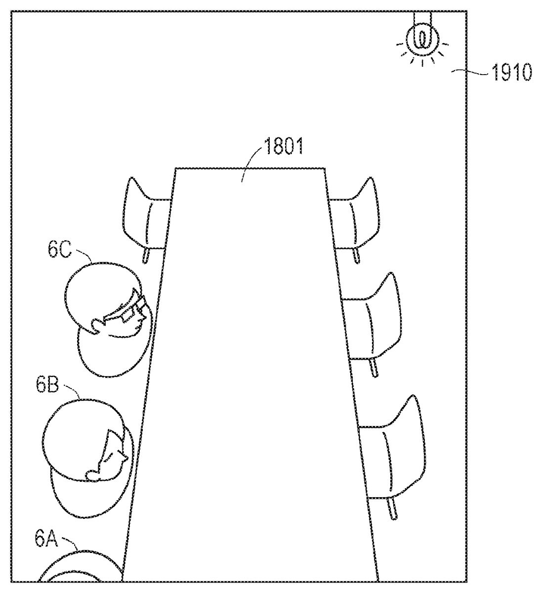
In at least one aspect, the virtual object generation module1425generates data for presenting a map object containing one or more location options selectable by the user5in the virtual space11. The field-of-image generation module1439generates data for presenting a field of view containing the map object based on the data for output to the monitor130. The map object is presented, for example, at an upper position in the virtual space11. The map object is not necessarily presented at an upper position in the virtual space11, and may be presented at any position as long as the map object does not impair the visibility of other existing objects (e.g., avatar objects of other users, chairs, and tables). When the monitor130displays the field of view based on the data, the user5recognizes the map object in the virtual space11. The map object is constructed so as to represent locations selectable by one or more users sharing the virtual space11in bird's eye view, for example. The map object contains one or more selectable sub-items. In at least one embodiment, the sub-items correspond to seats. Seats not used by the other users may be location options that can be selected by the user5for movement.
The user5can operate the controller300to select any one of seats in the map object. When the user5selects a seat, the movement management module1427determines that a location option corresponding to the seat is selected. In at least one aspect, when the user5directs his or her line of sight toward the map object, the line-of-sight detection module1426detects the line of sight of the user5that is directed toward the map object based on a signal output by the eye gaze sensor140. When the user5continues to look at any one of location options in the map object for a predetermined period of time, the movement management module1427determines the location option as a movement destination of the avatar object corresponding to the user5. The field-of-image generation module1439generates a field-of-view image for moving the point of view of the user5in the virtual space11to the location option based on the determination for output to the monitor130. When the user5wearing the HMD120visually recognizes an image displayed on the monitor130, the user5can recognize the fact that the user5has moved to the selected location option.
For example, in a case where the virtual space11is a conference room, when the user5at the entrance of the conference room looks at the ceiling of the conference room, a map object is presented. The map object corresponds to seats provided around a table in the conference room. Seats already occupied by avatar objects corresponding to the other users and vacant seats are presented in a distinguishable manner in the map object. The vacant seats are selectable by the user5as location options. The user5can operate the controller300to select a vacant seat as a movement destination location. In at least one aspect, when the user5continues to look at any one of the vacant seats, the vacant seat may be determined as the movement destination location. After that, when the user5performs a predetermined motion as a motion for establishing the selection, the user5moves to the location. For example, when the user5presses an OK button of the controller300, the vacant seat is established as the movement destination location. As a result, the point of view (namely, virtual camera14) of the user5moves to that location.
In at least one aspect, the virtual object generation module1425detects a motion of the user5based on a signal output from the motion sensor420, the HMD sensor410, or the eye gaze sensor140, and generates data for presenting a map object in response to the detection. The motion of the user5includes, for example, operation of the controller300, change of the direction of the line of sight, and change of the posture. The change of the direction of the line of sight includes looking up or down in the panorama image13. The change of the posture includes, for example, extending his or her body to look across an avatar object of another user present just in front of the line of sight of the user5. When such a motion is detected, the map object is presented in the virtual space11. With this configuration, the map object is presented in the virtual space11in synchronization with a usual motion of the user5in the real space. Therefore, implementing movement without impairing the sense of immersion into the virtual space11is possible.
In at least one aspect, the user5may look back depending on the situation of the virtual space11. When the HMD120includes an acceleration sensor and the user5wearing the HMD120turns his or her head, a signal output from the acceleration sensor is input to the computer200. The virtual object generation module1425generates data for presenting a map object including location options that are located backward of the current location of the user5based on the fact that the user5has looked backward, and outputs the data to the monitor130. For example, in a case where the user5is at the front of a university classroom presented in the virtual space11, when the user5turns his or her head backward, a map object representing seats located at the back of the classroom is presented so as to enter the field of view of the user5. When the user5operates the controller300to select any one of the location options presented in the map object, the location option becomes a selected state. Then, when the user5performs an operation of establishing the selection, the selection of that location option is established. The virtual camera14is moved to the location, and the field-of-image generation module1439generates data for displaying an image as viewed from that location, and outputs the data to the monitor130. The user5can look ahead from the back of the classroom.
In at least one aspect, the user5may be moved based on motions of the other users5B to5D sharing the virtual space11. For example, when an avatar object corresponding to the user5B moves to a new location in the virtual space11, the avatar object is presented at the new location in a field-of-view image visually recognized by the user5. At this point in time, location options selectable by the user5are changed, and thus the virtual object generation module1425may generate a map object having updated location options for presentation in the virtual space11in order to induce the user5to select a new location option. The user5can select a movement location based on the map object, and thus duplication of movement with the other users5B to5D is prevented.
In at least one aspect, the map object generated by the virtual object generation module1425includes the viewpoint position of the user5and the positions of the other users5B to5D sharing the virtual space11in the virtual space11. The viewpoint position of the user5and the positions of the other users5B to5D may be displayed in different modes. The movement management module1427receives selection of a location option that excludes the viewpoint position of the user5and the positions of the other users5B to5D. In this manner, the user5can select a movement destination while recognizing his or her own position.
In at least one aspect, the virtual object generation module1425generates data for presenting an object (e.g., arrow object) indicating a direction of existence of the map object after the viewpoint of the user5has moved in the virtual space11. When the arrow object is presented in the virtual space11, the user5can check the location of the map object by looking at the arrow object even after movement in the virtual space11. Therefore, the user5can easily grasp the position after movement.
In at least one aspect, the movement management module1427records a movement path of the viewpoint of the user5in the virtual space11into the memory module530. The virtual object generation module1425generates, based on an operation by the user5, data for presenting a path object indicating the movement path in the virtual space11using history data stored in the memory module530. The history data is stored in the server600, and is transmitted from the server600to the computer200in response to a request of the computer200. When the field-of-image generation module1439outputs the generated data to the monitor130, an object representing movement in the virtual space11is presented. The object is displayed as, for example, a polyline connecting points. The points each indicate a location in the virtual space. The line includes an arrow, and the arrow indicates the order of movement. When the user5visually recognizes the object, the user5can check the locus of his or her movement in the virtual space11. The field-of-image generation module1439may generate an image in which the viewpoint of the user5is returned to a position before movement based on an operation by the user5. With this, the user5can easily cancel movement also in the virtual space11.
The chat control module1428controls communication via the virtual space. In at least one aspect, the chat control module1428reads a chat application from the memory module530based on an operation by the user5or a request for starting a chat transmitted by another computer200B, to thereby start communication via the virtual space11. When the user5performs a login operation, e.g., inputs a user ID and a password into the computer200, the user5is associated with a session (also referred to as “room”) of a chat as one member of the chat via the virtual space11. After that, when the user5B using the computer200B logs in to the chat of the session, the user5and the user5B are associated with each other as members of the chat. When the chat control module1428identifies the user5B of the computer200B, who is to be a communication partner of the computer200, the virtual object generation module1425uses the object information1432to generate data for presenting an avatar object corresponding to the user5B, and outputs the data to the HMD120. When the HMD120displays the avatar object corresponding to the user5B on the monitor130based on the data, the user5wearing the HMD120recognizes the avatar object in the virtual space11.
In at least one embodiment of this disclosure, the chat control module1428waits for input of sound data that is based on a detected utterance of the user5and input of data from the eye gaze sensor140. When the user5performs an operation (e.g., operation of controller, gesture, selection by voice, or gaze by line of sight) for selecting an avatar object in the virtual space11, the chat control module1428detects, based on the operation, the fact that the user (e.g., user5) corresponding to the avatar object is selected as the chat partner. When the chat control module1428detects utterance of the user5, the chat control module1428transmits sound data that is based on a signal transmitted by the microphone170and eye tracking data that is based on a signal transmitted by the eye gaze sensor140to the computer200B via the communication control module240based on a network address of the computer200B used by the user5B. The computer200B updates the line of sight of the avatar object of the user5based on the eye tracking data, and transmits the sound data to the HMD120B. When the computer200B has a synchronization function, the line of sight of the avatar object is changed on the monitor130and sound is output from the speaker180substantially at the same timing, and thus the user5B is less likely to feel strange.
The space information1431stores one or more templates that are defined to provide the virtual space11.
The object information1432stores data for displaying an avatar object to be used for communication via the virtual space11, content to be reproduced in the virtual space11, and information for arranging an object to be used in the content. The content may include, for example, game content and content representing landscapes that resemble those of the real society. The data for displaying an avatar object may contain, for example, image data schematically representing a communication partner who is established as a chat partner in advance, and a photograph of the communication partner.
The user information1433stores, for example, a program for causing the computer200to function as a control device for the HMD set110, an application program that uses each piece of content stored in the object information1432, and a user ID and a password that are, in some instances, required to execute the application program. The data and programs stored in the memory module530are input by the user5of the HMD120. Alternatively, the processor210downloads programs or data from a computer (e.g., server600) that is managed by a business operator providing the content, and stores the downloaded programs or data into the memory module530.
The avatar position information1434contains position information on avatar objects used by respective users sharing the virtual space11. In at least one aspect, the position information is managed by the server600. After each user logs in to a room for a chat, when each user performs an operation of moving an avatar object in the virtual space11, the position information on the avatar object is updated. The data structure of the server600is described later.
[Operation Between Computers Through Communication Between Two Users]
Now, a description is given of operation of the computers200A and200B at the time when the two users5A and5B communicate to/from each other via the virtual space11. In the following, a description is given of a case in which the user5B wearing the HMD120B connected to the computer200B utters sound toward the user5A wearing the HMD120A connected to the computer200A.
(Transmission Side)
In at least one aspect, the user5B wearing the HMD120B utters sound toward the microphone170in order to chat with the user5A. The sound signal of the utterance is transmitted to the computer200B connected to the HMD120B. The sound control module1429converts the sound signal into sound data, and associates a timestamp representing the time of detection of the utterance with the sound data. The timestamp is, for example, time data of an internal clock of the processor210B. In at least one aspect, time data on a time when the communication control module240converts the sound signal into sound data is used as the timestamp.
When the user5B is uttering sound, a motion of the line of sight of the user5B is detected by the eye gaze sensor140. The result (eye tracking data) of detection by the eye gaze sensor140is transmitted to the computer200B. The line-of-sight detection module1426identifies each position (e.g., position of pupil) representing a change in line of sight of the user5B based on the detection result.
The computer200B transmits the sound data and the eye tracking data to the computer200A. The sound data and the eye tracking data are first transmitted to the server600. The server600refers to a destination of each header of the sound data and the eye tracking data, and transmits the sound data and the eye tracking data to the computer200A. At this time, the sound data and the eye tracking data may arrive at the computer200A at different times.
(Reception Side)
The computer200A receives the data transmitted by the computer200B from the server600. In at least one aspect, the processor210A of the computer200A detects reception of the sound data based on the data transmitted by the communication control module240. When the processor210A identifies the transmission source (i.e., computer200B) of the sound data, the processor210A serves as the chat control module1428to cause a chat screen to be displayed on the monitor130of the HMD120A.
The processor210A further detects reception of the eye tracking data. When the processor210A identifies a transmission source (i.e., computer200B) of the eye tracking data, the processor210serves as the virtual object generation module1425to generate data for displaying the avatar object of the user5B.
In at least one aspect, the processor210A may receive eye tracking data before reception of sound data. In this case, when detecting the transmission source identification number from the eye tracking data, the processor210A determines that there is sound data transmitted in association with the eye tracking data. The processor210A waits to output data for displaying an avatar object until the processor210A receives sound data containing the same transmission source identification number and time data as the transmission source identification number and time data contained in the eye tracking data.
Further, in at least one aspect, the processor210A may receive sound data before reception of eye tracking data. In this case, when detecting the transmission source identification number from the sound data, the processor210A determines that there is eye tracking data transmitted in association with the sound data. The processor210A waits to output the sound data until the processor210A receives eye tracking data containing the same transmission source identification number and time data as the transmission source identification number and time data contained in the sound data.
In each aspect described above, pieces of time data to be compared may not completely indicate the same time.
When confirming reception of sound data and eye tracking data containing the same time data, the processor210A outputs the sound data to the speaker180, and outputs, to the monitor130, data for displaying an avatar object in which the change that is based on the eye tracking data is translated. As a result, the user5can recognize the sound uttered by the user5B and the avatar at the same timing, and thus can enjoy a chat without feeling a time lag (e.g., deviation between change in avatar object and timing of outputting sound) due to delay of signal transmission.
In the same manner as in the processing described above, the processor210B of the computer200B used by the user5B can also synchronize the timing of outputting sound data and the timing of outputting an avatar object in which the movement of the line of sight of the user5is translated. As a result, the user5B can also recognize output of the sound uttered by the user5A and the change in avatar object at the same timing, and thus can enjoy a chat without feeling a time lag due to delay of signal transmission.
[Data Structure of Server]
With reference toFIG. 15, a description is given of a data structure of the server600.FIG. 15is a diagram of a mode of storage of data in the memory620included in the server600according to at least one embodiment of this disclosure. The memory620stores tables1510,1520, and1530.
The table1510contains data records of one or more users sharing the virtual space11by using a VR chat. Specifically, the table1510contains a user ID1511, a name1512, a login status1513, a seating status1514, a seating location1515, and position information1516. The user ID1511represents a user registered to be capable of sharing the virtual space11. The name1512represents the name of each user. The login status1513represents whether or not each user is logged in. For example, the login status1513represents whether or not each user shares the virtual space11at some point in time. The seating status1514represents the seating status of each user at a location option presented in the virtual space11. The location option represents a seat in, for example, a conference room, a movie theater, or a theater. The position information1516represents a location of the user in the virtual space11.
The table1520represents the usage status of each location option. The table1520is used to represent the status of the map object. The table1520includes a location option1521and a status1522. The location option1521specifies each location provided in the virtual space11. For example, seats may be specified in a manner that resembles that of a movie theater or a theater. In at least one aspect, when seats are arranged to surround a table in a conference room, numbers are used in an ascending order of 1, 2, 3, . . . , n, or in a descending order of n, n−1, . . . , 1.
The table1530stores history information on movement of each user in the virtual space11. The table1530contains a record number1531, a user ID1532, position information1533, and time information1534. The record number1531identifies a movement event that has occurred in a session that used the virtual space11in at least one aspect. The user ID1532identifies a user who has moved in the session. The position information1533identifies a position of the user in the virtual space11. In at least one aspect, the position information1533is represented based on three-dimensional coordinate axes (x, y, z) in the virtual space11. The time information1534represents a timing at which the user has moved to a position indicated by the position information1533.
When the server600detects movement of each user in the virtual space11, the memory620accumulates data in the movement history. The movement path is identified by connecting location points identified by the history of each movement. In at least one aspect, the server600transmits data representing the movement path to the computer200. The computer200can present a path object representing the movement path in the virtual space11based on the data. When the user5recognizes the path object, the user5can select a location before movement as necessary, and return to the location before movement.
[Control Structure]
With reference toFIG. 16, a description is given of a control structure of the computer200.FIG. 16is a flowchart of processing to be executed by the processor210of the computer200according to at least one embodiment of this disclosure.
In Step S1610, the processor210serves as the control module510to access the server600and display a service menu provided in the virtual space11on the monitor130based on an operation by the user5. Further, the processor210logs in to a VR chat service selected by the user5.
In Step S1615, the processor210serves as the control module510to transmit data for presenting the virtual space11on the HMD120. The user5wearing the HMD120recognizes the virtual space11via the monitor130.
In Step S1620, the processor210serves as the chat control module1428to receive list data from the server600, and outputs the received list data to the HMD120. When the monitor130displays a list of rooms based on the list data, the user5recognizes the list of rooms presented in the virtual space11.
In Step S1625, the processor210serves as the chat control module1428to select a room that the user5desires to enter based on an operation by the user5. For example, the user5can select a room using the controller300. In at least one aspect, when the user5keeps directing his or her line of sight toward any one of objects representing each room, the room is selected and the selection is established. In other cases, when a room is selected, the user enters the selected room. The HMD120presents a space after the user5has entered the room in the virtual space11. The processor210arranges the virtual camera14at an initial position determined in advance. This initial position is a viewpoint of the user5. The virtual space11may include a location option selectable by the user5in addition to an initial position. The user5can select any one of location options by keeping looking at the location option or operating the controller300. For example, the user5can select a movement destination location as long as there exists no avatar object of another user at that location in the virtual space11.
In Step S1630, the processor210serves as the movement management module1427to arrange the avatar object of the user5at a location corresponding to the selected location option. After that, when another user logs in to the same room, a computer used by another user transmits data on the login to the server600. The data contains a user ID, an initial position, and image data on the avatar object (or ID of avatar object).
In Step S1635, the processor210serves as the chat control module1428to receive data on other users who have entered the same room from the server600, and presents avatar objects of the other users in the virtual space11. Similarly to the case of the user5, the avatar objects of the other users are arranged at locations where the avatar object of the user5is not arranged.
In Step S1640, the processor210serves as the line-of-sight detection module1426to detect the fact that the user5is looking at some point in a ceiling based on a signal output from the eye gaze sensor140. Step S1640is not limited to detecting a line of sight directed at a point in the ceiling and is applicable to detecting a line of sight directed to other locations in the virtual space11. The processor210transmits, to the server600, a request for transmitting information representing a situation of arrangement of avatar objects in response to the detection. The server600reads the information (e.g., table1510ofFIG. 15) from the memory620in response to the transmission request, and transmits the read information to the computer200.
In Step S1645, the processor210serves as the control module510to present a map object representing a seating status of each user in the virtual space11based on the information received from the server600.
In Step S1650, the processor210serves as the movement management module1427to detect selection of a vacant seat based on output from the controller300or a signal output from the eye gaze sensor140. When an operation of establishing the selection, for example, pressing of a button or gazing for a fixed period of time, is performed, this vacant seat is determined as a location option serving as a movement destination of the avatar object of the user5.
In Step S1655, the processor210serves as the movement management module1427to move the avatar object of the user5to the selected vacant seat. The location of the virtual camera14corresponds to the movement destination location of the avatar object. The information on the position after movement is transmitted from the computer200to the server600. The processor610updates the table1510, and stores the history into the table1530.
In Step S1660, the processor210presents the map object, which is obtained after the avatar object of the user5is moved, in the virtual space11. For example, the map object is presented in the virtual space11until a predetermined period of time (e.g., few seconds) have elapsed after the avatar object is moved, and after that, the presentation ends. With this, the user5can easily grasp his or her own position even after movement in the virtual space11.
[Control Structure of Server]
With reference toFIG. 17, a description is given of a control structure of the server600.FIG. 17is a flowchart of the processing to be executed by the processor610of the server600according to at least one embodiment of this disclosure.
In Step S1710, the processor610receives login information to a chat room from each computer. The reception timing differs depending on each user. The processor610stores the login information on each user into the memory620, and updates the table1510. The server600initializes the table1520. The number of tables1520provided by the server600may correspond to the number of VR chat rooms provided by the server600. For example, when four rooms are provided, a table that corresponds to each room is created.
In Step S1720, the processor610receives, from the computer200, a request for transmitting data for displaying a map object. In at least one aspect, the data contains information representing an arrangement situation of each avatar object. In Step S1730, the processor610transmits data for displaying a map object to the computer in response to the transmission request.
In Step S1740, the processor610receives, from the computer200, position information on a movement destination location selected from location options. In Step S1750, the processor610uses the position information to update the login information stored in the memory620. More specifically, the processor610updates each item of the table1510and the table1520. Further, the processor610stores the movement history of the user into the table1530.
In Step S1760, the processor610transmits the updated login information, namely, pieces of data of the tables1510and1520to each computer. When the computer200receives the login information, the computer200updates the avatar position information1434. The virtual object generation module1425uses the updated avatar position information1434to generate data for presenting a map object. The field-of-image generation module1439uses the data to generate data for displaying a field-of-view image, and outputs the generated data to the monitor130. When the monitor130displays a map object that is based on the data, the user5can check his or her position after movement or the positions of the other users.
With reference toFIG. 18toFIG. 22, a description is given of at least one aspect of the movement in the virtual space11.FIG. 18is a diagram of a field-of-view image1817according to at least one embodiment of this disclosure.FIG. 19is a diagram of a state in which an object for displaying a map object is presented according to at least one embodiment of this disclosure. The field-of-view image1817is presented on the HMD120by login of the user5A to the room. For example, the field-of-view image1817is presented when the user5A has logged in to a room “conference room”.
InFIG. 18, the field-of-view image1817contains an object1801, an avatar object6A, an avatar object6B, an avatar object6C, and an object1840. The object1801corresponds to a virtually arranged table. The avatar object6A corresponds to the user5A. The avatar objects6B and6C correspond to the other users5B and5C, who have logged in to the same room. The object1840represents the chair of a vacant seat. The object1840is located within the line of sight of the user5A, namely, within the line of sight of the virtual camera14, and thus displayed on the field-of-view image1817. There is a chair selectable by the user between the avatar object6B and the avatar object6C as well, but the chair is not visible from the avatar object6A.
InFIG. 19, in at least one aspect, when the user5A looks up in the conference room in the virtual space11, an object1910is presented. The mode of the object1910is not particularly limited. The object1910may be an object such as a ball, a lamp, or a question mark, to attract the attention of each user in the virtual space11. Such an object may be transparent, or may flash. When the user5A selects or keeps looking at the object1910, the movement management module1427detects selection of the object1910. The virtual object generation module1425generates data for presenting the map object based on the result of detection, and the field-of-image generation module1439outputs the data to the monitor130.
FIG. 20is a diagram of a mode of a map object2000according to at least one embodiment of this disclosure. The map object2000contains images2001,2010,2020,2030,2040, and2050. The image2001corresponds to the object1801. The image2010corresponds to the user5A in the virtual space11. The images2020and2040correspond to the objects6B and6C representing other users, respectively. The images2030and2050represent vacant seats. Among those images, the image2050corresponds to the object1840. The image2050corresponds to a chair that is not located within the field of view of the user5A inFIG. 18orFIG. 19. The images2030and2050are displayed in modes different from display modes of the images2010,2020, and2040. Thus, the user5A can easily recognize selectable location options. In at least one aspect, the user5A can operate the controller300to select the image2030, namely, a movement destination location. In at least one aspect, when the user5A keeps looking at the image2030, the image2030is selected as a movement destination location, and the selection may be established when the user5A keeps looking at the image2030for a longer period of time. The user5A moves to the location identified by the image2030.
FIG. 21is a diagram of the field-of-view region15to be visually recognized at a location to which the user5has moved in the virtual space11according to at least one embodiment of this disclosure. The object6A corresponds to the user5A. Therefore, the user5can understand the fact that the user5has moved to a seat on the right of the object6C. In at least one aspect, the processor210presents an object2110representing an arrow in the field-of-view region15. The object2110represents the fact that the object1910for movement has been presented in a direction indicated by the arrow. The user5can recognize the object2110, to thereby check the current position after movement.
FIG. 22is a diagram of a mode of the map object2000to be presented according to at least one embodiment of this disclosure. The map object2200is presented at a location determined in advance for a predetermined period of time after the user5has moved in the virtual space11. The location determined in advance includes, for example, an upper position in the field-of-view region15and a back surface of an object that is arranged last in the field-of-view region15. The map object2200may be transparent. With this, visibility in the field-of-view region15is less likely to be hindered, and thus the user5can easily grasp the current location after movement in the virtual space11.FIGS. 20 and 22distinguish between a location occupied by the avatar object of the user5and other avatar objects based on different shapes for the corresponding images. In at least one embodiment, a map object distinguishes between locations occupied by different avatar objects based on distinguishing features other than shapes, such as color, shading, transparency, etc.FIGS. 20 and 22distinguish between a location occupied by other avatar objects and vacant locations based on shading. In at least one embodiment, a map object distinguishes between locations of avatar objects and vacant locations based on distinguishing features other than shading, such as shape, color, transparency, etc.
With reference toFIG. 23andFIG. 24, a description is further given of movement in the virtual space11.FIG. 23is a diagram of a field-of-view image2300according to at least one embodiment of this disclosure. The field-of-view image2300is, for example, a theater in the virtual space11. The field-of-view image2300includes a screen object2310and a seat object2320. As described above, when the user5keeps looking at a location determined in advance, a map object2330is presented.
FIG. 24is a diagram of the map object2330according to at least one embodiment of this disclosure. In the seat object2320, the map object2330includes seats. Apart of those seats may already be occupied by another user. Thus, inFIG. 24, vacant seats and used seats are distinguished from one another in the map object2330. For example, a region2410represents the fact that a seat is already used. The seat at this time is managed by the server600as A5(seat5in row A). Similarly, other hatched regions are already used. An unhatched region, for example, a region2420, represents the fact that the seat is not occupied. Thus, each user can select the seat as the movement destination in the virtual space11.
With reference toFIG. 25, a description is given of presentation of a history of movement in the virtual space11.FIG. 25is a diagram of a state in which a history of movement in the virtual space11is presented according to at least one embodiment of this disclosure. In at least one aspect, the processor210may present a polyline object2510based on data of the table1530stored in the server600. The polyline object2510represents the fact that the user5wearing the HMD120has moved in the virtual space11. The polyline object2510contains points2511,2512,2513, and2514. Those points are connected by arrows. The points are associated with pieces of position information. The polyline object2510represents the fact that the user5has moved in the order of the point2511, the point2512, the point2513, and the point2514in the virtual space11, and the fact that the current location of the user5is identified by the point2514.
For example, the polyline object2510is presented in the virtual space11when presentation of the history is set on. When the user5selects any one of points other than the point2514indicating the current location in the polyline object2510, the user5can return to the selected point. Alternatively, in at least one aspect, the user5selects an arrow instead of selecting a point. Also in this case, the user5moves to a point corresponding to a starting point of the selected arrow. With such a configuration, movement can be canceled when grasp of the current position becomes difficult in the virtual space11. Therefore, convenience of movement in the virtual space11becomes less likely to be impaired.
As described above, according to at least one embodiment of this disclosure, the map object representing a vacant state of a seat is presented in the virtual space11, and thus the user5can refer to the map object to easily move to a location that cannot be visually recognized in the virtual space11.
SUMMARY
The technical features described above in detail may be summarized as follows.
[Configuration 1]
According to at least one embodiment of this disclosure, there is provided a method to be executed on a computer200to move in a virtual space11provided by an HMD120. This method includes defining the virtual space11. The method further includes arranging an object (e.g., objects6B,6C,1840, and1910) visually recognizable by a user5of the HMD120in the virtual space11. The method further includes presenting a map object2330including one or more location options selectable by the user5in the virtual space11. The method further includes receiving selection of any one of the one or more location options included in the map object2330. The method further includes moving a viewpoint of the user5in the virtual space11to the selected one of the one or more location options.
[Configuration 2]
According to at least one embodiment of this disclosure, the presenting of the map object2330includes presenting the map object2330based on a motion of the user5. For example, when the user5performs a motion of looking up in the virtual space11, that motion triggers presentation of a menu. Therefore, movement in the virtual space11without a complicated operation is possible.
[Configuration 3]
According to at least one embodiment of this disclosure, the motion of the user5includes changing a direction of a line of sight by the user5. The presenting of the map object2330includes presenting the map object2330when the user5has changed the direction of the line of sight. With such a configuration, the user5may move in the virtual space11with a natural motion.
[Configuration 4]
According to at least one embodiment of this disclosure, the changing of the direction of the line of sight by the user5includes moving the line of sight of the user5toward an upper direction. The presenting of the map object includes presenting the map object when the line of sight of the user5has moved toward the upper direction. For example, when the user5looks up, a transparent ball is displayed. When the user5keeps looking at the ball, a location option to which the user5can move may be displayed. With this, a movement destination option is easily presented, and thus a complicated operation is avoided.
[Configuration 5]
According to at least one embodiment of this disclosure, the changing of the direction of the line of sight by the user5includes moving the line of sight toward a rear direction by the user5. The presenting of the map object2330includes presenting the map object including a location option that is located at the back of a current location of the user5based on the user5looking backward. With such a configuration, the user5can easily move even when the user5moves backward from the current location in the virtual space11.
[Configuration 6]
According to at least one embodiment of this disclosure, the method further includes detecting a motion of the HMD120. The presenting of the map object2330includes presenting the map object2330when the HMD120has moved. With such a configuration, for example, the map object2330is presented even when the head (HMD) of the user5has moved (e.g., turned left or right), and thus the user5can move in accordance with the intention of the user5.
[Configuration 7]
According to at least one embodiment of this disclosure, the method further includes establishing communication to/from other users5B and5C via the virtual space11. The arranging of the object includes arranging avatar objects6B and6C representing the other users5B and5C. The presenting of the map object2330includes presenting the map object2330based on the motions of the other users5B and5C. With such a configuration, the map object2330is presented in the field-of-view region15of the user5B based on the motions of the users5B and5C serving as communication partners. Therefore, the trigger for movement in the virtual space11may be diversified.
[Configuration 8]
According to at least one embodiment of this disclosure, the presenting of the map object2330includes presenting (FIG. 20) a position of the viewpoint of the user5in the virtual space11and positions of the other users5B and5C sharing the virtual space11. The receiving of the selection includes receiving selection of a location option where the viewpoint of the user5and the other users5B and5C are not present. With such a configuration, the user5can select a location where the other users5B and5C are not present.
[Configuration 9]
According to at least one embodiment of this disclosure, the method further includes presenting an object2110indicating a direction in which an avatar object is present after movement of the viewpoint of the user5in the virtual space11. With such a configuration, the direction of an indicator serving as a mark is presented after movement in the virtual space11. Therefore, the user5can easily check the current position even after movement.
[Configuration 10]
According to at least one embodiment of this disclosure, the method further includes recording a movement path of the viewpoint of the user5in the virtual space11. The method further includes presenting an object (e.g., polyline object2510) representing the movement path in the virtual space11. With such a configuration, the movement locus is presented in the virtual space11, and thus the user5can easily return to a position before movement as desired.
[Configuration 11]
According to at least one embodiment of this disclosure, the method further includes receiving an instruction to cancel movement of the viewpoint of the user5in the virtual space11. The method further includes returning the viewpoint of the user5to the location before movement based on the instruction. With such a configuration, the user5can easily return to an original position also in the virtual space11.
[Configuration 12]
According to at least one embodiment of this disclosure, the receiving of the instruction to cancel the movement includes receiving an operation to select a movement path included in a path object. With such a configuration, the user5can easily return to the position before movement simply by selecting a path presented in the virtual space11.
[Configuration 13]
According to at least one embodiment of this disclosure, the receiving of the operation to select the movement path includes detecting a line of sight directed toward the movement path included in the path object. With such a configuration, the path can be selected by the line of sight without using a hand, and thus a wider variety of operation methods for canceling movement are obtained.
The embodiments disclosed herein are merely examples in all aspects and in no way intended to limit this disclosure. The scope of this disclosure is defined by the appended claims and not by the above description, and this disclosure encompasses all modifications made within the scope and spirit equivalent to those of the appended claims.
In the at least one embodiment described above, the description is given by exemplifying the virtual space (VR space) in which the user is immersed using an HMD. However, a see-through HMD may be adopted as the HMD. In this case, the user may be provided with a virtual experience in an augmented reality (AR) space or a mixed reality (MR) space through output of a field-of-view image that is a combination of the real space visually recognized by the user via the see-through HMD and a part of an image forming the virtual space. In this case, action may be exerted on a target object in the virtual space based on motion of a hand of the user instead of the operation object. Specifically, the processor may identify coordinate information on the position of the hand of the user in the real space, and define the position of the target object in the virtual space in connection with the coordinate information in the real space. With this, the processor can grasp the positional relationship between the hand of the user in the real space and the target object in the virtual space, and execute processing corresponding to, for example, the above-mentioned collision control between the hand of the user and the target object. As a result, an action is exerted on the target object based on motion of the hand of the user.
Claims
- A method, comprising: defining a virtual space, wherein the virtual space comprises a viewpoint associated with a first user, a first object, and a map object, and wherein a plurality of location options is associated with the map object;defining a visual field based on a position of the viewpoint in the virtual space;generating a visual-field image based on the visual field;displaying the map object in the visual field in response to detection of a predetermined motion;identifying occupied location options from the plurality of location options;receiving a selection of any location option of the plurality of location options by the first user, wherein the receiving the selection comprises preventing the first user from selecting any location option of the plurality of location options identified as occupied;moving the viewpoint to the selected location option;and updating the visual field based on a position of the selected viewpoint in the virtual space.
- The method according to claim 1 , further comprising: hiding the map object from the first user prior to displaying the map object in the visual field.
- The method according to claim 1 , wherein the predetermined motion comprises changing a direction of a line of sight of the first user, and wherein the method further comprises displaying the map object in the visual field in response to the change of the direction of the line of sight.
- The method according to claim 3 , further comprising displaying the map object in the visual field in response to the line of sight being directed toward an upper direction in the virtual space.
- The method according to claim 3 , further comprising: defining a front and a back of the virtual space based on the position of the viewpoint in the virtual space;defining a first option, which is a location option of the plurality of location options included in the front of the virtual space;defining a second option, which is a location option of the plurality of location options included in the back of the virtual space;displaying the map object associated with the first option in the visual field in response to the line of sight being directed toward the front;and displaying the map object associated with the second option in the visual field in response to the line of sight being directed toward the back.
- The method according to claim 1 , wherein the predetermined motion comprises a motion of a head mounted device (HMD) configured to display the visual-field image, and wherein the method further comprises displaying the map object in the visual field in response to the detected motion of the HMD.
- The method according to claim 1 , wherein the first object comprises an avatar object associated with a second user, and wherein the method further comprises: receiving data for identifying a motion of the second user;and displaying the map object in the visual field depending on the motion of the second user.
- The method according to claim 7 , further comprising: identifying a position of the avatar object in the virtual space depending on a position of the viewpoint after movement in the virtual space;and displaying a second object indicating the position of the avatar object in the updated visual field.
- The method according to claim 1 , wherein the first object comprises an avatar object associated with a second user, wherein the map object includes a position of the viewpoint in the virtual space and a position of the avatar object in the virtual space, and wherein the identifying occupied location options comprises identifying the position of the viewpoint and the position of the avatar object as occupied.
- The method according to claim 1 , further comprising: recording a movement path of the viewpoint in the virtual space;and displaying a path object representing the movement path in the virtual space.
- The method according to claim 10 , further comprising: receiving an instruction to cancel movement of the viewpoint in the virtual space;and returning the viewpoint to a location prior to the canceled movement based on the instruction.
- The method according to claim 11 , further comprising: receiving, from the first user, an operation to select a position corresponding to the movement path included in the path object;and returning the viewpoint to the location prior to the canceled movement based on the operation.
- The method according to claim 12 , further comprising: identifying a line of sight of the first user;detecting the operation in response to the line of sight being directed toward the movement path included in the path object;and returning the viewpoint to the location prior to the canceled movement based on the operation.
- The method according to claim 1 , wherein displaying the map object comprises: displaying a first location option of the plurality of location options using a first icon;and displaying a second location option of the plurality of location options using a second icon different from the first icon.
- The method according to claim 14 , wherein the first location option is a location option of the viewpoint, and the second location option is a location option occupied by an avatar object associate with a second user.
- The method according to claim 14 , wherein the first location option is a location option of the viewpoint, and the second location option is an unoccupied location option.
- The method according to claim 14 , wherein the first location option is a location option of an avatar object associated with a second user, and the second location option is an unoccupied location option.
- The method according to claim 1 , wherein the displaying of the map object comprises displaying each location option of the plurality of location options.
- The method according to claim 18 , wherein the displaying each location option comprises: displaying occupied location options of the plurality of location options using a different mode from unoccupied location options of the plurality of location options.
- The method according to claim 18 , wherein the displaying each location option comprises: displaying occupied location options of the plurality of location options using a different icon from unoccupied location options of the plurality of location options.
Disclaimer: Data collected from the USPTO and may be malformed, incomplete, and/or otherwise inaccurate.