U.S. Pat. No. 10,445,917
METHOD FOR COMMUNICATION VIA VIRTUAL SPACE, NON-TRANSITORY COMPUTER READABLE MEDIUM FOR STORING INSTRUCTIONS FOR EXECUTING THE METHOD ON A COMPUTER, AND INFORMATION PROCESSING SYSTEM FOR EXECUTING THE METHOD
AssigneeCOLOPL, INC.
Issue DateDecember 6, 2017
Illustrative Figure
Abstract
A method includes defining a virtual space, wherein the virtual space comprises a first avatar object associated with a first user. The method further includes detecting a motion of a portion of a face of the first user. The method further includes generating face data representing the detected motion of the portion of the face. The method further includes modifying the face data to change a magnitude of the detected motion of the portion of the face. The method further includes controlling a face of the first avatar object based on the face data or the modified face data.
Description
DETAILED DESCRIPTION Now, with reference to the drawings, embodiments of this technical idea are described in detail. In the following description, like components are denoted by like reference symbols. The same applies to the names and functions of those components. Therefore, detailed description of those components is not repeated. In one or more embodiments described in this disclosure, components of respective embodiments can be combined with each other, and the combination also serves as a part of the embodiments described in this disclosure. [Configuration of HMD System] With reference toFIG. 1, a configuration of a head-mounted device (HMD) system100is described.FIG. 1is a diagram of a system100including a head-mounted display (HMD) according to at least one embodiment of this disclosure. The system100is usable for household use or for professional use. The system100includes a server600, HMD sets110A,110B,110C, and110D, an external device700, and a network2. Each of the HMD sets110A,110B,110C, and110D is capable of independently communicating to/from the server600or the external device700via the network2. In some instances, the HMD sets110A,110B,110C, and110D are also collectively referred to as “HMD set110”. The number of HMD sets110constructing the HMD system100is not limited to four, but may be three or less, or five or more. The HMD set110includes an HMD120, a computer200, an HMD sensor410, a display430, and a controller300. The HMD120includes a monitor130, an eye gaze sensor140, a first camera150, a second camera160, a microphone170, and a speaker180. In at least one embodiment, the controller300includes a motion sensor420. In at least one aspect, the computer200is connected to the network2, for example, the Internet, and is able to communicate to/from the server600or other computers connected to the network2in a wired or wireless manner. Examples of the other computers include a computer of another HMD set110or the external device700. In at least one aspect, the HMD120includes a sensor190instead ...
DETAILED DESCRIPTION
Now, with reference to the drawings, embodiments of this technical idea are described in detail. In the following description, like components are denoted by like reference symbols. The same applies to the names and functions of those components. Therefore, detailed description of those components is not repeated. In one or more embodiments described in this disclosure, components of respective embodiments can be combined with each other, and the combination also serves as a part of the embodiments described in this disclosure.
[Configuration of HMD System]
With reference toFIG. 1, a configuration of a head-mounted device (HMD) system100is described.FIG. 1is a diagram of a system100including a head-mounted display (HMD) according to at least one embodiment of this disclosure. The system100is usable for household use or for professional use.
The system100includes a server600, HMD sets110A,110B,110C, and110D, an external device700, and a network2. Each of the HMD sets110A,110B,110C, and110D is capable of independently communicating to/from the server600or the external device700via the network2. In some instances, the HMD sets110A,110B,110C, and110D are also collectively referred to as “HMD set110”. The number of HMD sets110constructing the HMD system100is not limited to four, but may be three or less, or five or more. The HMD set110includes an HMD120, a computer200, an HMD sensor410, a display430, and a controller300. The HMD120includes a monitor130, an eye gaze sensor140, a first camera150, a second camera160, a microphone170, and a speaker180. In at least one embodiment, the controller300includes a motion sensor420.
In at least one aspect, the computer200is connected to the network2, for example, the Internet, and is able to communicate to/from the server600or other computers connected to the network2in a wired or wireless manner. Examples of the other computers include a computer of another HMD set110or the external device700. In at least one aspect, the HMD120includes a sensor190instead of the HMD sensor410. In at least one aspect, the HMD120includes both sensor190and the HMD sensor410.
The HMD120is wearable on a head of a user5to display a virtual space to the user5during operation. More specifically, in at least one embodiment, the HMD120displays each of a right-eye image and a left-eye image on the monitor130. Each eye of the user5is able to visually recognize a corresponding image from the right-eye image and the left-eye image so that the user5may recognize a three-dimensional image based on the parallax of both of the user's the eyes. In at least one embodiment, the HMD120includes any one of a so-called head-mounted display including a monitor or a head-mounted device capable of mounting a smartphone or other terminals including a monitor.
The monitor130is implemented as, for example, a non-transmissive display device. In at least one aspect, the monitor130is arranged on a main body of the HMD120so as to be positioned in front of both the eyes of the user5. Therefore, when the user5is able to visually recognize the three-dimensional image displayed by the monitor130, the user5is immersed in the virtual space. In at least one aspect, the virtual space includes, for example, a background, objects that are operable by the user5, or menu images that are selectable by the user5. In at least one aspect, the monitor130is implemented as a liquid crystal monitor or an organic electroluminescence (EL) monitor included in a so-called smartphone or other information display terminals.
In at least one aspect, the monitor130is implemented as a transmissive display device. In this case, the user5is able to see through the HMD120covering the eyes of the user5, for example, smartglasses. In at least one embodiment, the transmissive monitor130is configured as a temporarily non-transmissive display device through adjustment of a transmittance thereof. In at least one embodiment, the monitor130is configured to display a real space and a part of an image constructing the virtual space simultaneously. For example, in at least one embodiment, the monitor130displays an image of the real space captured by a camera mounted on the HMD120, or may enable recognition of the real space by setting the transmittance of a part the monitor130sufficiently high to permit the user5to see through the HMD120.
In at least one aspect, the monitor130includes a sub-monitor for displaying a right-eye image and a sub-monitor for displaying a left-eye image. In at least one aspect, the monitor130is configured to integrally display the right-eye image and the left-eye image. In this case, the monitor130includes a high-speed shutter. The high-speed shutter operates so as to alternately display the right-eye image to the right of the user5and the left-eye image to the left eye of the user5, so that only one of the user's5eyes is able to recognize the image at any single point in time.
In at least one aspect, the HMD120includes a plurality of light sources (not shown). Each light source is implemented by, for example, a light emitting diode (LED) configured to emit an infrared ray. The HMD sensor410has a position tracking function for detecting the motion of the HMD120. More specifically, the HMD sensor410reads a plurality of infrared rays emitted by the HMD120to detect the position and the inclination of the HMD120in the real space.
In at least one aspect, the HMD sensor410is implemented by a camera. In at least one aspect, the HMD sensor410uses image information of the HMD120output from the camera to execute image analysis processing, to thereby enable detection of the position and the inclination of the HMD120.
In at least one aspect, the HMD120includes the sensor190instead of, or in addition to, the HMD sensor410as a position detector. In at least one aspect, the HMD120uses the sensor190to detect the position and the inclination of the HMD120. For example, in at least one embodiment, when the sensor190is an angular velocity sensor, a geomagnetic sensor, or an acceleration sensor, the HMD120uses any or all of those sensors instead of (or in addition to) the HMD sensor410to detect the position and the inclination of the HMD120. As an example, when the sensor190is an angular velocity sensor, the angular velocity sensor detects over time the angular velocity about each of three axes of the HMD120in the real space. The HMD120calculates a temporal change of the angle about each of the three axes of the HMD120based on each angular velocity, and further calculates an inclination of the HMD120based on the temporal change of the angles.
The eye gaze sensor140detects a direction in which the lines of sight of the right eye and the left eye of the user5are directed. That is, the eye gaze sensor140detects the line of sight of the user5. The direction of the line of sight is detected by, for example, a known eye tracking function. The eye gaze sensor140is implemented by a sensor having the eye tracking function. In at least one aspect, the eye gaze sensor140includes a right-eye sensor and a left-eye sensor. In at least one embodiment, the eye gaze sensor140is, for example, a sensor configured to irradiate the right eye and the left eye of the user5with an infrared ray, and to receive reflection light from the cornea and the iris with respect to the irradiation light, to thereby detect a rotational angle of each of the user's5eyeballs. In at least one embodiment, the eye gaze sensor140detects the line of sight of the user5based on each detected rotational angle.
The first camera150photographs a lower part of a face of the user5. More specifically, the first camera150photographs, for example, the nose or mouth of the user5. The second camera160photographs, for example, the eyes and eyebrows of the user5. A side of a casing of the HMD120on the user5side is defined as an interior side of the HMD120, and a side of the casing of the HMD120on a side opposite to the user5side is defined as an exterior side of the HMD120. In at least one aspect, the first camera150is arranged on an exterior side of the HMD120, and the second camera160is arranged on an interior side of the HMD120. Images generated by the first camera150and the second camera160are input to the computer200. In at least one aspect, the first camera150and the second camera160are implemented as a single camera, and the face of the user5is photographed with this single camera.
The microphone170converts an utterance of the user5into a voice signal (electric signal) for output to the computer200. The speaker180converts the voice signal into a voice for output to the user5. In at least one embodiment, the speaker180converts other signals into audio information provided to the user5. In at least one aspect, the HMD120includes earphones in place of the speaker180.
The controller300is connected to the computer200through wired or wireless communication. The controller300receives input of a command from the user5to the computer200. In at least one aspect, the controller300is held by the user5. In at least one aspect, the controller300is mountable to the body or a part of the clothes of the user5. In at least one aspect, the controller300is configured to output at least any one of a vibration, a sound, or light based on the signal transmitted from the computer200. In at least one aspect, the controller300receives from the user5an operation for controlling the position and the motion of an object arranged in the virtual space.
In at least one aspect, the controller300includes a plurality of light sources. Each light source is implemented by, for example, an LED configured to emit an infrared ray. The HMD sensor410has a position tracking function. In this case, the HMD sensor410reads a plurality of infrared rays emitted by the controller300to detect the position and the inclination of the controller300in the real space. In at least one aspect, the HMD sensor410is implemented by a camera. In this case, the HMD sensor410uses image information of the controller300output from the camera to execute image analysis processing, to thereby enable detection of the position and the inclination of the controller300.
In at least one aspect, the motion sensor420is mountable on the hand of the user5to detect the motion of the hand of the user5. For example, the motion sensor420detects a rotational speed, a rotation angle, and the number of rotations of the hand. The detected signal is transmitted to the computer200. The motion sensor420is provided to, for example, the controller300. In at least one aspect, the motion sensor420is provided to, for example, the controller300capable of being held by the user5. In at least one aspect, to help prevent accidently release of the controller300in the real space, the controller300is mountable on an object like a glove-type object that does not easily fly away by being worn on a hand of the user5. In at least one aspect, a sensor that is not mountable on the user5detects the motion of the hand of the user5. For example, a signal of a camera that photographs the user5may be input to the computer200as a signal representing the motion of the user5. As at least one example, the motion sensor420and the computer200are connected to each other through wired or wireless communication. In the case of wireless communication, the communication mode is not particularly limited, and for example, Bluetooth (trademark) or other known communication methods are usable.
The display430displays an image similar to an image displayed on the monitor130. With this, a user other than the user5wearing the HMD120can also view an image similar to that of the user5. An image to be displayed on the display430is not required to be a three-dimensional image, but may be a right-eye image or a left-eye image. For example, a liquid crystal display or an organic EL monitor may be used as the display430.
In at least one embodiment, the server600transmits a program to the computer200. In at least one aspect, the server600communicates to/from another computer200for providing virtual reality to the HMD120used by another user. For example, when a plurality of users play a participatory game, for example, in an amusement facility, each computer200communicates to/from another computer200via the server600with a signal that is based on the motion of each user, to thereby enable the plurality of users to enjoy a common game in the same virtual space. Each computer200may communicate to/from another computer200with the signal that is based on the motion of each user without intervention of the server600.
The external device700is any suitable device as long as the external device700is capable of communicating to/from the computer200. The external device700is, for example, a device capable of communicating to/from the computer200via the network2, or is a device capable of directly communicating to/from the computer200by near field communication or wired communication. Peripheral devices such as a smart device, a personal computer (PC), or the computer200are usable as the external device700, in at least one embodiment, but the external device700is not limited thereto.
[Hardware Configuration of Computer]
With reference toFIG. 2, the computer200in at least one embodiment is described.FIG. 2is a block diagram of a hardware configuration of the computer200according to at least one embodiment. The computer200includes, a processor210, a memory220, a storage230, an input/output interface240, and a communication interface250. Each component is connected to a bus260. In at least one embodiment, at least one of the processor210, the memory220, the storage230, the input/output interface240or the communication interface250is part of a separate structure and communicates with other components of computer200through a communication path other than the bus260.
The processor210executes a series of commands included in a program stored in the memory220or the storage230based on a signal transmitted to the computer200or in response to a condition determined in advance. In at least one aspect, the processor210is implemented as a central processing unit (CPU), a graphics processing unit (GPU), a micro-processor unit (MPU), a field-programmable gate array (FPGA), or other devices.
The memory220temporarily stores programs and data. The programs are loaded from, for example, the storage230. The data includes data input to the computer200and data generated by the processor210. In at least one aspect, the memory220is implemented as a random access memory (RAM) or other volatile memories.
The storage230permanently stores programs and data. In at least one embodiment, the storage230stores programs and data for a period of time longer than the memory220, but not permanently. The storage230is implemented as, for example, a read-only memory (ROM), a hard disk device, a flash memory, or other non-volatile storage devices. The programs stored in the storage230include programs for providing a virtual space in the system100, simulation programs, game programs, user authentication programs, and programs for implementing communication to/from other computers200. The data stored in the storage230includes data and objects for defining the virtual space.
In at least one aspect, the storage230is implemented as a removable storage device like a memory card. In at least one aspect, a configuration that uses programs and data stored in an external storage device is used instead of the storage230built into the computer200. With such a configuration, for example, in a situation in which a plurality of HMD systems100are used, for example in an amusement facility, the programs and the data are collectively updated.
The input/output interface240allows communication of signals among the HMD120, the HMD sensor410, the motion sensor420, and the display430. The monitor130, the eye gaze sensor140, the first camera150, the second camera160, the microphone170, and the speaker180included in the HMD120may communicate to/from the computer200via the input/output interface240of the HMD120. In at least one aspect, the input/output interface240is implemented with use of a universal serial bus (USB), a digital visual interface (DVI), a high-definition multimedia interface (HDMI) (trademark), or other terminals. The input/output interface240is not limited to the specific examples described above.
In at least one aspect, the input/output interface240further communicates to/from the controller300. For example, the input/output interface240receives input of a signal output from the controller300and the motion sensor420. In at least one aspect, the input/output interface240transmits a command output from the processor210to the controller300. The command instructs the controller300to, for example, vibrate, output a sound, or emit light. When the controller300receives the command, the controller300executes any one of vibration, sound output, and light emission in accordance with the command.
The communication interface250is connected to the network2to communicate to/from other computers (e.g., server600) connected to the network2. In at least one aspect, the communication interface250is implemented as, for example, a local area network (LAN), other wired communication interfaces, wireless fidelity (Wi-Fi), Bluetooth®, near field communication (NFC), or other wireless communication interfaces. The communication interface250is not limited to the specific examples described above.
In at least one aspect, the processor210accesses the storage230and loads one or more programs stored in the storage230to the memory220to execute a series of commands included in the program. In at least one embodiment, the one or more programs includes an operating system of the computer200, an application program for providing a virtual space, and/or game software that is executable in the virtual space. The processor210transmits a signal for providing a virtual space to the HMD120via the input/output interface240. The HMD120displays a video on the monitor130based on the signal.
InFIG. 2, the computer200is outside of the HMD120, but in at least one aspect, the computer200is integral with the HMD120. As an example, a portable information communication terminal (e.g., smartphone) including the monitor130functions as the computer200in at least one embodiment.
In at least one embodiment, the computer200is used in common with a plurality of HMDs120. With such a configuration, for example, the computer200is able to provide the same virtual space to a plurality of users, and hence each user can enjoy the same application with other users in the same virtual space.
According to at least one embodiment of this disclosure, in the system100, a real coordinate system is set in advance. The real coordinate system is a coordinate system in the real space. The real coordinate system has three reference directions (axes) that are respectively parallel to a vertical direction, a horizontal direction orthogonal to the vertical direction, and a front-rear direction orthogonal to both of the vertical direction and the horizontal direction in the real space. The horizontal direction, the vertical direction (up-down direction), and the front-rear direction in the real coordinate system are defined as an x axis, a y axis, and a z axis, respectively. More specifically, the x axis of the real coordinate system is parallel to the horizontal direction of the real space, the y axis thereof is parallel to the vertical direction of the real space, and the z axis thereof is parallel to the front-rear direction of the real space.
In at least one aspect, the HMD sensor410includes an infrared sensor. When the infrared sensor detects the infrared ray emitted from each light source of the HMD120, the infrared sensor detects the presence of the HMD120. The HMD sensor410further detects the position and the inclination (direction) of the HMD120in the real space, which corresponds to the motion of the user5wearing the HMD120, based on the value of each point (each coordinate value in the real coordinate system). In more detail, the HMD sensor410is able to detect the temporal change of the position and the inclination of the HMD120with use of each value detected over time.
Each inclination of the HMD120detected by the HMD sensor410corresponds to an inclination about each of the three axes of the HMD120in the real coordinate system. The HMD sensor410sets a uvw visual-field coordinate system to the HMD120based on the inclination of the HMD120in the real coordinate system. The uvw visual-field coordinate system set to the HMD120corresponds to a point-of-view coordinate system used when the user5wearing the HMD120views an object in the virtual space.
[Uvw Visual-Field Coordinate System]
With reference toFIG. 3, the uvw visual-field coordinate system is described.FIG. 3is a diagram of a uvw visual-field coordinate system to be set for the HMD120according to at least one embodiment of this disclosure. The HMD sensor410detects the position and the inclination of the HMD120in the real coordinate system when the HMD120is activated. The processor210sets the uvw visual-field coordinate system to the HMD120based on the detected values.
InFIG. 3, the HMD120sets the three-dimensional uvw visual-field coordinate system defining the head of the user5wearing the HMD120as a center (origin). More specifically, the HMD120sets three directions newly obtained by inclining the horizontal direction, the vertical direction, and the front-rear direction (x axis, y axis, and z axis), which define the real coordinate system, about the respective axes by the inclinations about the respective axes of the HMD120in the real coordinate system, as a pitch axis (u axis), a yaw axis (v axis), and a roll axis (w axis) of the uvw visual-field coordinate system in the HMD120.
In at least one aspect, when the user5wearing the HMD120is standing (or sitting) upright and is visually recognizing the front side, the processor210sets the uvw visual-field coordinate system that is parallel to the real coordinate system to the HMD120. In this case, the horizontal direction (x axis), the vertical direction (y axis), and the front-rear direction (z axis) of the real coordinate system directly match the pitch axis (u axis), the yaw axis (v axis), and the roll axis (w axis) of the uvw visual-field coordinate system in the HMD120, respectively.
After the uvw visual-field coordinate system is set to the HMD120, the HMD sensor410is able to detect the inclination of the HMD120in the set uvw visual-field coordinate system based on the motion of the HMD120. In this case, the HMD sensor410detects, as the inclination of the HMD120, each of a pitch angle (θu), a yaw angle (θv), and a roll angle (θw) of the HMD120in the uvw visual-field coordinate system. The pitch angle (θu) represents an inclination angle of the HMD120about the pitch axis in the uvw visual-field coordinate system. The yaw angle (θv) represents an inclination angle of the HMD120about the yaw axis in the uvw visual-field coordinate system. The roll angle (θw) represents an inclination angle of the HMD120about the roll axis in the uvw visual-field coordinate system.
The HMD sensor410sets, to the HMD120, the uvw visual-field coordinate system of the HMD120obtained after the movement of the HMD120based on the detected inclination angle of the HMD120. The relationship between the HMD120and the uvw visual-field coordinate system of the HMD120is constant regardless of the position and the inclination of the HMD120. When the position and the inclination of the HMD120change, the position and the inclination of the uvw visual-field coordinate system of the HMD120in the real coordinate system change in synchronization with the change of the position and the inclination.
In at least one aspect, the HMD sensor410identifies the position of the HMD120in the real space as a position relative to the HMD sensor410based on the light intensity of the infrared ray or a relative positional relationship between a plurality of points (e.g., distance between points), which is acquired based on output from the infrared sensor. In at least one aspect, the processor210determines the origin of the uvw visual-field coordinate system of the HMD120in the real space (real coordinate system) based on the identified relative position.
[Virtual Space]
With reference toFIG. 4, the virtual space is further described.FIG. 4is a diagram of a mode of expressing a virtual space11according to at least one embodiment of this disclosure. The virtual space11has a structure with an entire celestial sphere shape covering a center12in all 360-degree directions. InFIG. 4, for the sake of clarity, only the upper-half celestial sphere of the virtual space11is included. Each mesh section is defined in the virtual space11. The position of each mesh section is defined in advance as coordinate values in an XYZ coordinate system, which is a global coordinate system defined in the virtual space11. The computer200associates each partial image forming a panorama image13(e.g., still image or moving image) that is developed in the virtual space11with each corresponding mesh section in the virtual space11.
In at least one aspect, in the virtual space11, the XYZ coordinate system having the center12as the origin is defined. The XYZ coordinate system is, for example, parallel to the real coordinate system. The horizontal direction, the vertical direction (up-down direction), and the front-rear direction of the XYZ coordinate system are defined as an X axis, a Y axis, and a Z axis, respectively. Thus, the X axis (horizontal direction) of the XYZ coordinate system is parallel to the x axis of the real coordinate system, the Y axis (vertical direction) of the XYZ coordinate system is parallel to the y axis of the real coordinate system, and the Z axis (front-rear direction) of the XYZ coordinate system is parallel to the z axis of the real coordinate system.
When the HMD120is activated, that is, when the HMD120is in an initial state, a virtual camera14is arranged at the center12of the virtual space11. In at least one embodiment, the virtual camera14is offset from the center12in the initial state. In at least one aspect, the processor210displays on the monitor130of the HMD120an image photographed by the virtual camera14. In synchronization with the motion of the HMD120in the real space, the virtual camera14similarly moves in the virtual space11. With this, the change in position and direction of the HMD120in the real space is reproduced similarly in the virtual space11.
The uvw visual-field coordinate system is defined in the virtual camera14similarly to the case of the HMD120. The uvw visual-field coordinate system of the virtual camera14in the virtual space11is defined to be synchronized with the uvw visual-field coordinate system of the HMD120in the real space (real coordinate system). Therefore, when the inclination of the HMD120changes, the inclination of the virtual camera14also changes in synchronization therewith. The virtual camera14can also move in the virtual space11in synchronization with the movement of the user5wearing the HMD120in the real space.
The processor210of the computer200defines a field-of-view region15in the virtual space11based on the position and inclination (reference line of sight16) of the virtual camera14. The field-of-view region15corresponds to, of the virtual space11, the region that is visually recognized by the user5wearing the HMD120. That is, the position of the virtual camera14determines a point of view of the user5in the virtual space11.
The line of sight of the user5detected by the eye gaze sensor140is a direction in the point-of-view coordinate system obtained when the user5visually recognizes an object. The uvw visual-field coordinate system of the HMD120is equal to the point-of-view coordinate system used when the user5visually recognizes the monitor130. The uvw visual-field coordinate system of the virtual camera14is synchronized with the uvw visual-field coordinate system of the HMD120. Therefore, in the system100in at least one aspect, the line of sight of the user5detected by the eye gaze sensor140can be regarded as the line of sight of the user5in the uvw visual-field coordinate system of the virtual camera14.
[User's Line of Sight]
With reference toFIG. 5, determination of the line of sight of the user5is described.FIG. 5is a plan view diagram of the head of the user5wearing the HMD120according to at least one embodiment of this disclosure.
In at least one aspect, the eye gaze sensor140detects lines of sight of the right eye and the left eye of the user5. In at least one aspect, when the user5is looking at a near place, the eye gaze sensor140detects lines of sight R1and L1. In at least one aspect, when the user5is looking at a far place, the eye gaze sensor140detects lines of sight R2and L2. In this case, the angles formed by the lines of sight R2and L2with respect to the roll axis w are smaller than the angles formed by the lines of sight R1and L1with respect to the roll axis w. The eye gaze sensor140transmits the detection results to the computer200.
When the computer200receives the detection values of the lines of sight R1and L1from the eye gaze sensor140as the detection results of the lines of sight, the computer200identifies a point of gaze N1being an intersection of both the lines of sight R1and L1based on the detection values. Meanwhile, when the computer200receives the detection values of the lines of sight R2and L2from the eye gaze sensor140, the computer200identifies an intersection of both the lines of sight R2and L2as the point of gaze. The computer200identifies a line of sight NO of the user5based on the identified point of gaze N1. The computer200detects, for example, an extension direction of a straight line that passes through the point of gaze N1and a midpoint of a straight line connecting a right eye R and a left eye L of the user5to each other as the line of sight NO. The line of sight NO is a direction in which the user5actually directs his or her lines of sight with both eyes. The line of sight NO corresponds to a direction in which the user5actually directs his or her lines of sight with respect to the field-of-view region15.
In at least one aspect, the system100includes a television broadcast reception tuner. With such a configuration, the system100is able to display a television program in the virtual space11.
In at least one aspect, the HMD system100includes a communication circuit for connecting to the Internet or has a verbal communication function for connecting to a telephone line or a cellular service.
[Field-of-View Region]
With reference toFIG. 6andFIG. 7, the field-of-view region15is described.FIG. 6is a diagram of a YZ cross section obtained by viewing the field-of-view region15from an X direction in the virtual space11.FIG. 7is a diagram of an XZ cross section obtained by viewing the field-of-view region15from a Y direction in the virtual space11.
InFIG. 6, the field-of-view region15in the YZ cross section includes a region18. The region18is defined by the position of the virtual camera14, the reference line of sight16, and the YZ cross section of the virtual space11. The processor210defines a range of a polar angle α from the reference line of sight16serving as the center in the virtual space as the region18.
InFIG. 7, the field-of-view region15in the XZ cross section includes a region19. The region19is defined by the position of the virtual camera14, the reference line of sight16, and the XZ cross section of the virtual space11. The processor210defines a range of an azimuth β from the reference line of sight16serving as the center in the virtual space11as the region19. The polar angle α and β are determined in accordance with the position of the virtual camera14and the inclination (direction) of the virtual camera14.
In at least one aspect, the system100causes the monitor130to display a field-of-view image17based on the signal from the computer200, to thereby provide the field of view in the virtual space11to the user5. The field-of-view image17corresponds to a part of the panorama image13, which corresponds to the field-of-view region15. When the user5moves the HMD120worn on his or her head, the virtual camera14is also moved in synchronization with the movement. As a result, the position of the field-of-view region15in the virtual space11is changed. With this, the field-of-view image17displayed on the monitor130is updated to an image of the panorama image13, which is superimposed on the field-of-view region15synchronized with a direction in which the user5faces in the virtual space11. The user5can visually recognize a desired direction in the virtual space11.
In this way, the inclination of the virtual camera14corresponds to the line of sight of the user5(reference line of sight16) in the virtual space11, and the position at which the virtual camera14is arranged corresponds to the point of view of the user5in the virtual space11. Therefore, through the change of the position or inclination of the virtual camera14, the image to be displayed on the monitor130is updated, and the field of view of the user5is moved.
While the user5is wearing the HMD120(having a non-transmissive monitor130), the user5can visually recognize only the panorama image13developed in the virtual space11without visually recognizing the real world. Therefore, the system100provides a high sense of immersion in the virtual space11to the user5.
In at least one aspect, the processor210moves the virtual camera14in the virtual space11in synchronization with the movement in the real space of the user5wearing the HMD120. In this case, the processor210identifies an image region to be projected on the monitor130of the HMD120(field-of-view region15) based on the position and the direction of the virtual camera14in the virtual space11.
In at least one aspect, the virtual camera14includes two virtual cameras, that is, a virtual camera for providing a right-eye image and a virtual camera for providing a left-eye image. An appropriate parallax is set for the two virtual cameras so that the user5is able to recognize the three-dimensional virtual space11. In at least one aspect, the virtual camera14is implemented by a single virtual camera. In this case, a right-eye image and a left-eye image may be generated from an image acquired by the single virtual camera. In at least one embodiment, the virtual camera14is assumed to include two virtual cameras, and the roll axes of the two virtual cameras are synthesized so that the generated roll axis (w) is adapted to the roll axis (w) of the HMD120.
[Controller]
An example of the controller300is described with reference toFIG. 8AandFIG. 8B.FIG. 8Ais a diagram of a schematic configuration of a controller according to at least one embodiment of this disclosure.FIG. 8Bis a diagram of a coordinate system to be set for a hand of a user holding the controller according to at least one embodiment of this disclosure.
In at least one aspect, the controller300includes a right controller300R and a left controller (not shown). InFIG. 8Aonly right controller300R is shown for the sake of clarity. The right controller300R is operable by the right hand of the user5. The left controller is operable by the left hand of the user5. In at least one aspect, the right controller300R and the left controller are symmetrically configured as separate devices. Therefore, the user5can freely move his or her right hand holding the right controller300R and his or her left hand holding the left controller. In at least one aspect, the controller300may be an integrated controller configured to receive an operation performed by both the right and left hands of the user5. The right controller300R is now described.
The right controller300R includes a grip310, a frame320, and a top surface330. The grip310is configured so as to be held by the right hand of the user5. For example, the grip310may be held by the palm and three fingers (e.g., middle finger, ring finger, and small finger) of the right hand of the user5.
The grip310includes buttons340and350and the motion sensor420. The button340is arranged on a side surface of the grip310, and receives an operation performed by, for example, the middle finger of the right hand. The button350is arranged on a front surface of the grip310, and receives an operation performed by, for example, the index finger of the right hand. In at least one aspect, the buttons340and350are configured as trigger type buttons. The motion sensor420is built into the casing of the grip310. When a motion of the user5can be detected from the surroundings of the user5by a camera or other device. In at least one embodiment, the grip310does not include the motion sensor420.
The frame320includes a plurality of infrared LEDs360arranged in a circumferential direction of the frame320. The infrared LEDs360emit, during execution of a program using the controller300, infrared rays in accordance with progress of the program. The infrared rays emitted from the infrared LEDs360are usable to independently detect the position and the posture (inclination and direction) of each of the right controller300R and the left controller. InFIG. 8A, the infrared LEDs360are shown as being arranged in two rows, but the number of arrangement rows is not limited to that illustrated inFIG. 8. In at least one embodiment, the infrared LEDs360are arranged in one row or in three or more rows. In at least one embodiment, the infrared LEDs360are arranged in a pattern other than rows.
The top surface330includes buttons370and380and an analog stick390. The buttons370and380are configured as push type buttons. The buttons370and380receive an operation performed by the thumb of the right hand of the user5. In at least one aspect, the analog stick390receives an operation performed in any direction of 360 degrees from an initial position (neutral position). The operation includes, for example, an operation for moving an object arranged in the virtual space11.
In at least one aspect, each of the right controller300R and the left controller includes a battery for driving the infrared ray LEDs360and other members. The battery includes, for example, a rechargeable battery, a button battery, a dry battery, but the battery is not limited thereto. In at least one aspect, the right controller300R and the left controller are connectable to, for example, a USB interface of the computer200. In at least one embodiment, the right controller300R and the left controller do not include a battery.
InFIG. 8AandFIG. 8B, for example, a yaw direction, a roll direction, and a pitch direction are defined with respect to the right hand of the user5. A direction of an extended thumb is defined as the yaw direction, a direction of an extended index finger is defined as the roll direction, and a direction perpendicular to a plane is defined as the pitch direction.
[Hardware Configuration of Server]
With reference toFIG. 9, the server600in at least one embodiment is described.FIG. 9is a block diagram of a hardware configuration of the server600according to at least one embodiment of this disclosure. The server600includes a processor610, a memory620, a storage630, an input/output interface640, and a communication interface650. Each component is connected to a bus660. In at least one embodiment, at least one of the processor610, the memory620, the storage630, the input/output interface640or the communication interface650is part of a separate structure and communicates with other components of server600through a communication path other than the bus660.
The processor610executes a series of commands included in a program stored in the memory620or the storage630based on a signal transmitted to the server600or on satisfaction of a condition determined in advance. In at least one aspect, the processor610is implemented as a central processing unit (CPU), a graphics processing unit (GPU), a micro processing unit (MPU), a field-programmable gate array (FPGA), or other devices.
The memory620temporarily stores programs and data. The programs are loaded from, for example, the storage630. The data includes data input to the server600and data generated by the processor610. In at least one aspect, the memory620is implemented as a random access memory (RAM) or other volatile memories.
The storage630permanently stores programs and data. In at least one embodiment, the storage630stores programs and data for a period of time longer than the memory620, but not permanently. The storage630is implemented as, for example, a read-only memory (ROM), a hard disk device, a flash memory, or other non-volatile storage devices. The programs stored in the storage630include programs for providing a virtual space in the system100, simulation programs, game programs, user authentication programs, and programs for implementing communication to/from other computers200or servers600. The data stored in the storage630may include, for example, data and objects for defining the virtual space.
In at least one aspect, the storage630is implemented as a removable storage device like a memory card. In at least one aspect, a configuration that uses programs and data stored in an external storage device is used instead of the storage630built into the server600. With such a configuration, for example, in a situation in which a plurality of HMD systems100are used, for example, as in an amusement facility, the programs and the data are collectively updated.
The input/output interface640allows communication of signals to/from an input/output device. In at least one aspect, the input/output interface640is implemented with use of a USB, a DVI, an HDMI, or other terminals. The input/output interface640is not limited to the specific examples described above.
The communication interface650is connected to the network2to communicate to/from the computer200connected to the network2. In at least one aspect, the communication interface650is implemented as, for example, a LAN, other wired communication interfaces, Wi-Fi, Bluetooth, NFC, or other wireless communication interfaces. The communication interface650is not limited to the specific examples described above.
In at least one aspect, the processor610accesses the storage630and loads one or more programs stored in the storage630to the memory620to execute a series of commands included in the program. In at least one embodiment, the one or more programs include, for example, an operating system of the server600, an application program for providing a virtual space, and game software that can be executed in the virtual space. In at least one embodiment, the processor610transmits a signal for providing a virtual space to the HMD device110to the computer200via the input/output interface640.
[Control Device of HMD]
With reference toFIG. 10, the control device of the HMD120is described. According to at least one embodiment of this disclosure, the control device is implemented by the computer200having a known configuration.FIG. 10is a block diagram of the computer200according to at least one embodiment of this disclosure.FIG. 10includes a module configuration of the computer200.
InFIG. 10, the computer200includes a control module510, a rendering module520, a memory module530, and a communication control module540. In at least one aspect, the control module510and the rendering module520are implemented by the processor210. In at least one aspect, a plurality of processors210function as the control module510and the rendering module520. The memory module530is implemented by the memory220or the storage230. The communication control module540is implemented by the communication interface250.
The control module510controls the virtual space11provided to the user5. The control module510defines the virtual space11in the HMD system100using virtual space data representing the virtual space11. The virtual space data is stored in, for example, the memory module530. In at least one embodiment, the control module510generates virtual space data. In at least one embodiment, the control module510acquires virtual space data from, for example, the server600.
The control module510arranges objects in the virtual space11using object data representing objects. The object data is stored in, for example, the memory module530. In at least one embodiment, the control module510generates virtual space data. In at least one embodiment, the control module510acquires virtual space data from, for example, the server600. In at least one embodiment, the objects include, for example, an avatar object of the user5, character objects, operation objects, for example, a virtual hand to be operated by the controller300, and forests, mountains, other landscapes, streetscapes, or animals to be arranged in accordance with the progression of the story of the game.
The control module510arranges an avatar object of the user5of another computer200, which is connected via the network2, in the virtual space11. In at least one aspect, the control module510arranges an avatar object of the user5in the virtual space11. In at least one aspect, the control module510arranges an avatar object simulating the user5in the virtual space11based on an image including the user5. In at least one aspect, the control module510arranges an avatar object in the virtual space11, which is selected by the user5from among a plurality of types of avatar objects (e.g., objects simulating animals or objects of deformed humans).
The control module510identifies an inclination of the HMD120based on output of the HMD sensor410. In at least one aspect, the control module510identifies an inclination of the HMD120based on output of the sensor190functioning as a motion sensor. The control module510detects parts (e.g., mouth, eyes, and eyebrows) forming the face of the user5from a face image of the user5generated by the first camera150and the second camera160. The control module510detects a motion (shape) of each detected part.
The control module510detects a line of sight of the user5in the virtual space11based on a signal from the eye gaze sensor140. The control module510detects a point-of-view position (coordinate values in the XYZ coordinate system) at which the detected line of sight of the user5and the celestial sphere of the virtual space11intersect with each other. More specifically, the control module510detects the point-of-view position based on the line of sight of the user5defined in the uvw coordinate system and the position and the inclination of the virtual camera14. The control module510transmits the detected point-of-view position to the server600. In at least one aspect, the control module510is configured to transmit line-of-sight information representing the line of sight of the user5to the server600. In such a case, the control module510may calculate the point-of-view position based on the line-of-sight information received by the server600.
The control module510translates a motion of the HMD120, which is detected by the HMD sensor410, in an avatar object. For example, the control module510detects inclination of the HMD120, and arranges the avatar object in an inclined manner. The control module510translates the detected motion of face parts in a face of the avatar object arranged in the virtual space11. The control module510receives line-of-sight information of another user5from the server600, and translates the line-of-sight information in the line of sight of the avatar object of another user5. In at least one aspect, the control module510translates a motion of the controller300in an avatar object and an operation object. In this case, the controller300includes, for example, a motion sensor, an acceleration sensor, or a plurality of light emitting elements (e.g., infrared LEDs) for detecting a motion of the controller300.
The control module510arranges, in the virtual space11, an operation object for receiving an operation by the user5in the virtual space11. The user5operates the operation object to, for example, operate an object arranged in the virtual space11. In at least one aspect, the operation object includes, for example, a hand object serving as a virtual hand corresponding to a hand of the user5. In at least one aspect, the control module510moves the hand object in the virtual space11so that the hand object moves in association with a motion of the hand of the user5in the real space based on output of the motion sensor420. In at least one aspect, the operation object may correspond to a hand part of an avatar object.
When one object arranged in the virtual space11collides with another object, the control module510detects the collision. The control module510is able to detect, for example, a timing at which a collision area of one object and a collision area of another object have touched with each other, and performs predetermined processing in response to the detected timing. In at least one embodiment, the control module510detects a timing at which an object and another object, which have been in contact with each other, have moved away from each other, and performs predetermined processing in response to the detected timing. In at least one embodiment, the control module510detects a state in which an object and another object are in contact with each other. For example, when an operation object touches another object, the control module510detects the fact that the operation object has touched the other object, and performs predetermined processing.
In at least one aspect, the control module510controls image display of the HMD120on the monitor130. For example, the control module510arranges the virtual camera14in the virtual space11. The control module510controls the position of the virtual camera14and the inclination (direction) of the virtual camera14in the virtual space11. The control module510defines the field-of-view region15depending on an inclination of the head of the user5wearing the HMD120and the position of the virtual camera14. The rendering module520generates the field-of-view region17to be displayed on the monitor130based on the determined field-of-view region15. The communication control module540outputs the field-of-view region17generated by the rendering module520to the HMD120.
The control module510, which has detected an utterance of the user5using the microphone170from the HMD120, identifies the computer200to which voice data corresponding to the utterance is to be transmitted. The voice data is transmitted to the computer200identified by the control module510. The control module510, which has received voice data from the computer200of another user via the network2, outputs audio information (utterances) corresponding to the voice data from the speaker180.
The memory module530holds data to be used to provide the virtual space11to the user5by the computer200. In at least one aspect, the memory module530stores space information, object information, and user information.
The space information stores one or more templates defined to provide the virtual space11.
The object information stores a plurality of panorama images13forming the virtual space11and object data for arranging objects in the virtual space11. In at least one embodiment, the panorama image13contains a still image and/or a moving image. In at least one embodiment, the panorama image13contains an image in a non-real space and/or an image in the real space. An example of the image in a non-real space is an image generated by computer graphics.
The user information stores a user ID for identifying the user5. The user ID is, for example, an internet protocol (IP) address or a media access control (MAC) address set to the computer200used by the user. In at least one aspect, the user ID is set by the user. The user information stores, for example, a program for causing the computer200to function as the control device of the HMD system100.
The data and programs stored in the memory module530are input by the user5of the HMD120. Alternatively, the processor210downloads the programs or data from a computer (e.g., server600) that is managed by a business operator providing the content, and stores the downloaded programs or data in the memory module530.
In at least one embodiment, the communication control module540communicates to/from the server600or other information communication devices via the network2.
In at least one aspect, the control module510and the rendering module520are implemented with use of, for example, Unity® provided by Unity Technologies. In at least one aspect, the control module510and the rendering module520are implemented by combining the circuit elements for implementing each step of processing.
The processing performed in the computer200is implemented by hardware and software executed by the processor410. In at least one embodiment, the software is stored in advance on a hard disk or other memory module530. In at least one embodiment, the software is stored on a CD-ROM or other computer-readable non-volatile data recording media, and distributed as a program product. In at least one embodiment, the software may is provided as a program product that is downloadable by an information provider connected to the Internet or other networks. Such software is read from the data recording medium by an optical disc drive device or other data reading devices, or is downloaded from the server600or other computers via the communication control module540and then temporarily stored in a storage module. The software is read from the storage module by the processor210, and is stored in a RAM in a format of an executable program. The processor210executes the program.
[Control Structure of HMD System]
With reference toFIG. 11, the control structure of the HMD set110is described.FIG. 11is a sequence chart of processing to be executed by the system100according to at least one embodiment of this disclosure.
InFIG. 11, in Step S1110, the processor210of the computer200serves as the control module510to identify virtual space data and define the virtual space11.
In Step S1120, the processor210initializes the virtual camera14. For example, in a work area of the memory, the processor210arranges the virtual camera14at the center12defined in advance in the virtual space11, and matches the line of sight of the virtual camera14with the direction in which the user5faces.
In Step S1130, the processor210serves as the rendering module520to generate field-of-view image data for displaying an initial field-of-view image. The generated field-of-view image data is output to the HMD120by the communication control module540.
In Step S1132, the monitor130of the HMD120displays the field-of-view image based on the field-of-view image data received from the computer200. The user5wearing the HMD120is able to recognize the virtual space11through visual recognition of the field-of-view image.
In Step S1134, the HMD sensor410detects the position and the inclination of the HMD120based on a plurality of infrared rays emitted from the HMD120. The detection results are output to the computer200as motion detection data.
In Step S1140, the processor210identifies a field-of-view direction of the user5wearing the HMD120based on the position and inclination contained in the motion detection data of the HMD120.
In Step S1150, the processor210executes an application program, and arranges an object in the virtual space11based on a command contained in the application program.
In Step S1160, the controller300detects an operation by the user5based on a signal output from the motion sensor420, and outputs detection data representing the detected operation to the computer200. In at least one aspect, an operation of the controller300by the user5is detected based on an image from a camera arranged around the user5.
In Step S1170, the processor210detects an operation of the controller300by the user5based on the detection data acquired from the controller300.
In Step S1180, the processor210generates field-of-view image data based on the operation of the controller300by the user5. The communication control module540outputs the generated field-of-view image data to the HMD120.
In Step S1190, the HMD120updates a field-of-view image based on the received field-of-view image data, and displays the updated field-of-view image on the monitor130.
[Avatar Object]
With reference toFIG. 12AandFIG. 12B, an avatar object according to at least one embodiment is described.FIG. 12andFIG. 12Bare diagrams of avatar objects of respective users5of the HMD sets110A and110B. In the following, the user of the HMD set110A, the user of the HMD set110B, the user of the HMD set110C, and the user of the HMD set110D are referred to as “user5A”, “user5B”, “user5C”, and “user5D”, respectively. A reference numeral of each component related to the HMD set110A, a reference numeral of each component related to the HMD set110B, a reference numeral of each component related to the HMD set110C, and a reference numeral of each component related to the HMD set110D are appended by A, B, C, and D, respectively. For example, the HMD120A is included in the HMD set110A.
FIG. 12Ais a schematic diagram of HMD systems of several users sharing the virtual space interact using a network according to at least one embodiment of this disclosure. Each HMD120provides the user5with the virtual space11. Computers200A to200D provide the users5A to5D with virtual spaces11A to11D via HMDs120A to120D, respectively. InFIG. 12A, the virtual space11A and the virtual space11B are formed by the same data. In other words, the computer200A and the computer200B share the same virtual space. An avatar object6A of the user5A and an avatar object6B of the user5B are present in the virtual space11A and the virtual space11B. The avatar object6A in the virtual space11A and the avatar object6B in the virtual space11B each wear the HMD120. However, the inclusion of the HMD120A and HMD120B is only for the sake of simplicity of description, and the avatars do not wear the HMD120A and HMD120B in the virtual spaces11A and11B, respectively.
In at least one aspect, the processor210A arranges a virtual camera14A for photographing a field-of-view region17A of the user5A at the position of eyes of the avatar object6A.
FIG. 12Bis a diagram of a field of view of a HMD according to at least one embodiment of this disclosure.FIG. 12(B)corresponds to the field-of-view region17A of the user5A inFIG. 12A. The field-of-view region17A is an image displayed on a monitor130A of the HMD120A. This field-of-view region17A is an image generated by the virtual camera14A. The avatar object6B of the user5B is displayed in the field-of-view region17A. Although not included inFIG. 12B, the avatar object6A of the user5A is displayed in the field-of-view image of the user5B.
In the arrangement inFIG. 12B, the user5A can communicate to/from the user5B via the virtual space11A through conversation. More specifically, voices of the user5A acquired by a microphone170A are transmitted to the HMD120B of the user5B via the server600and output from a speaker180B provided on the HMD120B. Voices of the user5B are transmitted to the HMD120A of the user5A via the server600, and output from a speaker180A provided on the HMD120A.
The processor210A translates an operation by the user5B (operation of HMD120B and operation of controller300B) in the avatar object6B arranged in the virtual space11A. With this, the user5A is able to recognize the operation by the user5B through the avatar object6B.
FIG. 13is a sequence chart of processing to be executed by the system100according to at least one embodiment of this disclosure. InFIG. 13, although the HMD set110D is not included, the HMD set110D operates in a similar manner as the HMD sets110A,110B, and110C. Also in the following description, a reference numeral of each component related to the HMD set110A, a reference numeral of each component related to the HMD set110B, a reference numeral of each component related to the HMD set110C, and a reference numeral of each component related to the HMD set110D are appended by A, B, C, and D, respectively.
In Step S1310A, the processor210A of the HMD set110A acquires avatar information for determining a motion of the avatar object6A in the virtual space11A. This avatar information contains information on an avatar such as motion information, face tracking data, and sound data. The motion information contains, for example, information on a temporal change in position and inclination of the HMD120A and information on a motion of the hand of the user5A, which is detected by, for example, a motion sensor420A. An example of the face tracking data is data identifying the position and size of each part of the face of the user5A. Another example of the face tracking data is data representing motions of parts forming the face of the user5A and line-of-sight data. An example of the sound data is data representing sounds of the user5A acquired by the microphone170A of the HMD120A. In at least one embodiment, the avatar information contains information identifying the avatar object6A or the user5A associated with the avatar object6A or information identifying the virtual space11A accommodating the avatar object6A. An example of the information identifying the avatar object6A or the user5A is a user ID. An example of the information identifying the virtual space11A accommodating the avatar object6A is a room ID. The processor210A transmits the avatar information acquired as described above to the server600via the network2.
In Step S1310B, the processor210B of the HMD set110B acquires avatar information for determining a motion of the avatar object6B in the virtual space11B, and transmits the avatar information to the server600, similarly to the processing of Step S1310A. Similarly, in Step S1310C, the processor210C of the HMD set110C acquires avatar information for determining a motion of the avatar object6C in the virtual space11C, and transmits the avatar information to the server600.
In Step S1320, the server600temporarily stores pieces of player information received from the HMD set110A, the HMD set110B, and the HMD set110C, respectively. The server600integrates pieces of avatar information of all the users (in this example, users5A to5C) associated with the common virtual space11based on, for example, the user IDs and room IDs contained in respective pieces of avatar information. Then, the server600transmits the integrated pieces of avatar information to all the users associated with the virtual space11at a timing determined in advance. In this manner, synchronization processing is executed. Such synchronization processing enables the HMD set110A, the HMD set110B, and the HMD120C to share mutual avatar information at substantially the same timing.
Next, the HMD sets110A to110C execute processing of Step S1330A to Step S1330C, respectively, based on the integrated pieces of avatar information transmitted from the server600to the HMD sets110A to110C. The processing of Step S1330A corresponds to the processing of Step S1180ofFIG. 11.
In Step S1330A, the processor210A of the HMD set110A updates information on the avatar object6B and the avatar object6C of the other users5B and5C in the virtual space11A. Specifically, the processor210A updates, for example, the position and direction of the avatar object6B in the virtual space11based on motion information contained in the avatar information transmitted from the HMD set110B. For example, the processor210A updates the information (e.g., position and direction) on the avatar object6B contained in the object information stored in the memory module530. Similarly, the processor210A updates the information (e.g., position and direction) on the avatar object6C in the virtual space11based on motion information contained in the avatar information transmitted from the HMD set110C.
In Step S1330B, similarly to the processing of Step S1330A, the processor210B of the HMD set110B updates information on the avatar object6A and the avatar object6C of the users5A and5C in the virtual space11B. Similarly, in Step S1330C, the processor210C of the HMD set110C updates information on the avatar object6A and the avatar object6B of the users5A and5B in the virtual space11C.
[Details of Module Configuration]
With reference toFIG. 14, details of a module configuration of the computer200are described.FIG. 14is a block diagram of a configuration of modules of the computer according to at least one embodiment of this disclosure.
InFIG. 14, the control module510includes a virtual camera control module1421, a field-of-view region determination module1422, a reference-line-of-sight identification module1423, a face part detection module1424, a motion detection module1425, a virtual space definition module1426, a virtual object generation module1427, an operation object control module1428, and an avatar control module1429. The rendering module520includes a field-of-view image generation module1438. The memory module530stores space information1431, object information1432, user information1433, and face information1434.
The virtual camera control module1421arranges the virtual camera14in the virtual space11. The virtual camera control module1421controls a position in the virtual space11at which the virtual camera14is arranged and the direction (inclination) of the virtual camera14. The field-of-view region determination module1422determines the field of view region15based on the direction of the head of the user wearing the HMD120and the position at which the virtual camera14is arranged. The field-of-view image generation module1438generates the field-of-view region17to be displayed on the monitor130based on the determined field of view region15.
The reference-line-of-sight identification module1423identifies the line of sight of the user5based on a signal from the eye gaze sensor140. The face part detection module1424detects parts (e.g., mouth, eyes, and eyebrows) of the face of the user5from the face image of the user5generated by the first camera150and the second camera160. The motion detection module1425detects a motion (shape) of each part detected by the face part detection module1424. Details of control of the face part detection module1424and the motion detection module1425are described later with reference toFIG. 15toFIG. 17.
The virtual space definition module1426generates virtual space data representing the virtual space11, to thereby define the virtual space11in the HMD system100.
The virtual object generation module1427generates objects to be arranged in the virtual space11. The objects may include, for example, forests, mountains, other landscapes, and animals to be arranged in accordance with the progression of the story of the game.
The operation object control module1428arranges, in the virtual space11, an operation object for receiving an operation of the user5in the virtual space11. The user operates the operation object to operate an object arranged in the virtual space11, for example. In at least one aspect, the operation object includes, for example, a hand object corresponding to the hand of the user wearing the HMD120. In at least one aspect, the operation object corresponds to a hand part of an avatar object described later.
The avatar control module1429generates data for arranging an avatar object of the user of another computer200, which is connected via the network2, in the virtual space11. In at least one aspect, the avatar control module1429generates data for arranging an avatar object of the user5in the virtual space11. In at least one aspect, the avatar control module1429generates an avatar object simulating the user5based on an image including the user5. In at least one aspect, the avatar control module1429generates data for arranging an avatar object in the virtual space2, which is selected by the user5from among a plurality of types of avatar objects (e.g., objects simulating animals or objects of deformed humans).
The avatar control module1429reflects a motion of the HMD120, which is detected by the HMD sensor410, in an avatar object. For example, the avatar control module1429detects inclination of the HMD120, and generates data for arranging the avatar object in an inclined manner. In at least one aspect, the avatar control module1429reflects a motion of the controller300in an avatar object. In this case, the controller300includes, for example, a motion sensor, an acceleration sensor, or a plurality of light emitting elements (e.g., infrared LEDs) for detecting a motion of the controller300. The avatar control module1429reflects motions of face parts detected by the motion detection module1425in the face of an avatar object arranged in the virtual space11. That is, the avatar control module1429reflects a motion of the face of the user5A in the avatar object.
When one object in the virtual space11collides with another object in the virtual space11, the control module510detects the collision. In at least one embodiment, the control module510detects, for example, a timing at which an object and the other object have touched with each other, and performs predetermined processing in response to the detected timing. In at least one embodiment, the control module510detects a timing at which an object and another object, which have been in contact with each other, have moved away from each other, and performs predetermined processing in response to the detected timing. In at least one embodiment, the control module510detects a state in which an object and the other object are in contact with each other. Specifically, when an operation object touches with another object, the operation object control module1428detects the fact that the operation object has touched the other object, and performs predetermined processing.
The memory module530stores data usable by the computer200to provide the user5with the virtual space11. In at least one aspect, the memory module530stores the space information1431, the object information1432, the user information1433, and the face information1434.
The space information1431stores one or more templates that are defined to provide the virtual space11.
The object information1432stores content to be reproduced in the virtual space11, objects to be used in the content, and information (e.g., positional information) for arranging objects in the virtual space11. The content may include, for example, game content and content representing landscapes that resemble those of the real world.
The user information1433stores, for example, a program for causing the computer200to function as a control device of the system.100and an application program that uses each content stored in the object information1432.
The face information1434stores templates, e.g., templates that are stored in advance, for the face part detection module1424to detect face parts of the user5. In at least one aspect, the face information1434stores a mouth template1435, an eye template1436, and an eyebrow template1437. In at least one embodiment, each template is an image corresponding to a different part of a face. For example, the mouth template1435is an image of a mouth. In at least one embodiment, each template includes a plurality of images. In at least one embodiment, an image of the plurality of images is selected for use with the user5in advance.
[Face Tracking]
In the following, with reference toFIG. 15toFIG. 17, a specific example of detecting a motion (shape) of the face of the user is described. InFIG. 15toFIG. 17, a specific example of detecting a motion of the mouth of the user is described as an example according to at least one embodiment of this disclosure. The detection method described with reference toFIG. 15toFIG. 17is not limited to detection of a motion of the mouth of the user, but may be applied to detection of motions of other parts (e.g., eyes or eyebrows) of the face of the user.
FIG. 15is a diagram of a mouth from a facial image1541of the user according to at least one embodiment of this disclosure. The facial image1541generated by the first camera150includes the nose and mouth of the user5.
The face part detection module1424identifies a mouth region1542from the facial image1541by pattern matching using the mouth template1435stored in the face information1434. In at least one aspect, the face part detection module1424sets a rectangular comparison region in the facial image1541, and changes the size, position, and angle of this comparison region to calculate a similarity degree between an image of the comparison region and an image of the mouth template1435. In at least one embodiment, a shape of the comparison region is a shape other than rectangular, e.g., elliptical. The face part detection module1424may identify, as the mouth region1542, a comparison region for which a similarity degree larger than a threshold value determined in advance is calculated.
In at least one embodiment, the face part detection module1424further determines whether or not the comparison region corresponds to the mouth region based on a relative positional relationship between positions of other face parts (e.g., eyes and nose) and the position of the comparison region for which the calculated similarity degree is larger than the threshold value.
The motion detection module1425detects a more detailed shape of the mouth from the mouth region1542detected by the face part detection module1424.
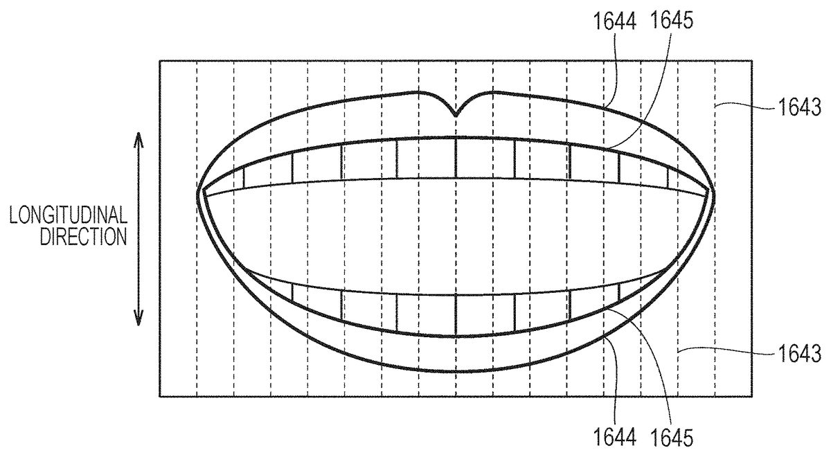
FIG. 16is a diagram of detection of the shape of the mouth by the motion detection module1425according to at least one embodiment of this disclosure. With reference toFIG. 16, the motion detection module1425sets a contour detection line1643for detecting the shape of the mouth (contour of lips) contained in the mouth region1542. A plurality of contour detection lines1643are set at predetermined intervals in a direction (hereinafter referred to as “lateral direction”) orthogonal to a height direction (hereinafter referred to as “longitudinal direction”) of the face.
In at least one embodiment, the motion detection module1425detects a change in brightness value of the mouth region1542along each of the plurality of contour detection lines1643, and identify a position at which the change in brightness value is abrupt as a contour point. More specifically, the motion detection module1425identifies, as the contour point, a pixel for which a brightness difference (namely, change in brightness value) between the pixel and an adjacent pixel is equal to or larger than a threshold value determined in advance, in at least one embodiment. The brightness value of a pixel is obtained by, for example, integrating RBG values of the pixel with predetermined weighting.
The motion detection module1425identifies two types of contour points from the image corresponding to the mouth region1542. The motion detection module1425identifies a contour point1644corresponding to a contour of the outer side of the mouth (lips) and a contour point1645corresponding to a contour of the inner side of the mouth (lips). In at least one aspect, when three or more contour points are detected on one contour detection line1643, the motion detection module1425identifies contour points on both ends of the contour detection line1643as the outer contour points1644. In this case, the motion detection module1425identifies contour points other than the outer contour points1644as the inner contour points1645. When two or less contour points are detected on one contour detection line1643, the motion detection module1425identifies the detected contour points as the outer contour points1644.
FIG. 17is a diagram of detection of the shape of the mouth by the motion detection module1425according to at least one embodiment of this disclosure. InFIG. 17, the outer contour points1644and the inner contour points1645are indicated by white circles and hatched circles, respectively.
The motion detection module1425interpolates points between the inner contour points1645to identify a mouth shape1746(size of mouth opening). In at least one aspect, the motion detection module1425identifies the mouth shape1746using a nonlinear interpolation method, for example, spline interpolation. In at least one aspect, the motion detection module1425identifies the mouth shape1746by interpolating points between the outer contour points1644. In at least one aspect, the motion detection module1425identifies the mouth shape1746by removing contour points that greatly deviate from an assumed mouth shape (predetermined shape that may be formed by upper lip and lower lip of person) and using left contour points. In this manner, the motion detection module1425may identify a motion (shape) of the mouth of the user. The method of detecting the mouth shape1746is not limited to the above, and the motion detection module1425may detect the mouth shape1746with another technique. The motion detection module1425may detect motions of other face parts of eyes and eyebrows of the user in the same manner.
FIGS. 18A and 18Bare diagrams of a comparison between a facial expression of the user in the real space and a facial expression of the avatar object of the user in the virtual space according to at least one embodiment of this disclosure.FIG. 18Ais a diagram of the user5B in the real space according to at least one embodiment of this disclosure.FIG. 18Bis a diagram of a field-of-view image1817A recognized by the user5A according to at least one embodiment of this disclosure.
With reference toFIG. 18A, the first camera150B and the second camera160B constructing the HMD set110B photograph the user5B. The user5B is smiling at the time of photography. InFIG. 18A, the user is wearing the HMD120B, but the HMD120B is omitted for the sake of clarity. The HMD is also omitted for similar diagrams described later.
The motion detection module1425detects the shape of the mouth of the user5B based on an image photographed by the first camera150B. The computer200B outputs data representing the detected shape (motion) of the mouth to the server600. The server600transfers the data to the computer200A, which shares the same virtual space11as that of the computer200B. An avatar control module1429A reflects the shape of the mouth of the user5B in the avatar object6B based on the data. With this, as inFIG. 18B, the avatar object6B displayed on the field-of-view image1817A of the user5A represents a facial expression of smiling.
[Control Structure of Server600]
FIG. 19is a diagram of a hardware configuration and a module configuration of the server600according to at least one embodiment of this disclosure. In one embodiment of this disclosure, the server600includes the communication interface650, the processor610, and the storage630.
The communication interface650functions as a communication module for wireless communication, which is configured to perform, for example, modulation/demodulation processing for transmitting/receiving signals to/from an external communication device, for example, the computer200. The communication interface650is implemented by, for example, a tuner or a high frequency circuit.
The processor610controls operation of the server600. The processor610executes various control programs stored in the storage630to function as a transmission/reception unit1951, a server processing unit1952, and a matching unit1953.
The transmission/reception unit1951transmits/receives various kinds of information to/from each computer200. For example, the transmission/reception unit1951transmits to each computer200a request for arranging objects in the virtual space11, a request for deleting objects from the virtual space11, a request for moving objects, voices of the user, or information for defining the virtual space11.
The server processing unit1952performs processing required for a plurality of users to share the same virtual space11. For example, the server processing unit1952updates avatar object information1956described later based on the information received from the computer200.
The matching unit1953performs a series of processing for associating a plurality of users with one another. For example, when an input operation for the plurality of users to share the same virtual space11is performed, the matching unit1953performs, for example, processing of associating users belonging to the virtual space11to one another.
The storage630stores virtual space designation information1954, object designation information1955, the avatar object information1956, and user information1959.
The virtual space designation information1954is information to be used by the virtual space definition module1426of the computer200to define the virtual space11. For example, the virtual space designation information1954contains information for designating the size of the virtual space11.
The object designation information1955designates an object to be arranged (generated) by the virtual object generation module1427of the computer200in the virtual space11.
The avatar object information1956contains face information1957and position information1958. The face information1957is information (face tracking data) representing a motion (shape) of each part (e.g., mouth, eyes, and eyebrows) forming the face of the user of the computer200. The face tracking data is an example of face data. The position information1958represents a position (coordinates) of each avatar object in the virtual space11. The avatar object information1956is updated as appropriate based on information input from the computer200.
The user information1959is information on the user5of the computer200. The user information1959contains, for example, identification information (e.g., user account) identifying the plurality of users5.
[Control for Reflecting Operation of User in Avatar Object]
With reference toFIG. 20, a method of controlling operation of an avatar object in the virtual space is described.FIG. 20is a flowchart of signals between the computer200and the server600for translating a motion of the user in the avatar object according to at least one embodiment of this disclosure. In at least one embodiment, the processing inFIG. 20is implemented by the processor210of the computer200executing a control program stored in the memory220or the storage230and the processor610of the server600executing a control program stored in the storage630.
In Step S2002, the processor610of the server600serves as the transmission/reception unit1951to transmit the virtual space designation information1954to the computers200A and200B based on requests for generating the virtual space, which are received from the computers200A and200B. At this time, in at least one embodiment, each computer200transmits identification information on the user5to the server600together with the virtual space designation information1954. Then, in at least one embodiment, the processor610serves as the matching unit1953to associate pieces of identification information on the computers200A and200B with each other to establish the fact that the users5A and5B share the same virtual space.
In Step S2004, the processor210A of the computer200A serves as a virtual space definition module1426A to define the virtual space11A based on the received virtual space designation information1954. In Step S2006, similarly to the processor210A, the processor210B of the computer200B defines the virtual space11B.
In Step S2008, the processor610outputs the object designation information1955for designating objects to be arranged in the virtual spaces11A and11B to the computers200A and200B.
In Step S2010, the processor210A serves as a virtual object generation module1427A to arrange objects in the virtual space11A based on the received object designation information1955. In Step S2012, the processor210B arranges objects in the virtual space11B similarly to the processor210A.
In Step S2014, the processor210A serves as an avatar control module1429A to arrange the avatar object6A (denoted by “own avatar object” inFIG. 20) of the user5A himself or herself in the virtual space11A. Then, the processor210A transmits information (e.g., data for modeling and positional information) on the avatar object6A to the server600.
In Step S2016, the processor610stores the received information on the avatar object6A into the storage630(avatar object information1956). The processor610further transmits the information on the avatar object6A to the computer200B sharing the same virtual space with the computer200A.
In Step S2018, the processor210B serves as an avatar control module1429B to arrange the avatar object6A in the virtual space11B based on the received information on the avatar object6A.
Similarly to Step S2014to Step S2018, in Step S2020to Step S2024, the avatar object6B is generated in the virtual spaces11A and11B (denoted by “another avatar object” inFIG. 20), and information on the avatar object6B is stored in the storage630.
In Step S2026, the processor210A photographs the face of the user5A with the first camera150A and the second camera160A to generate a facial image.
In Step S2028, the processor210A serves as the face part detection module1424A and the motion detection module1425A to detect face tracking data representing a motion (shape) of the face (e.g., mouth, eyes, and eyebrows) of the user5A. The processor210A further transmits the detected face tracking data to the server600.
In Step S2030, the processor210A serves as the avatar control module1429A to reflect the detected motion of the face of the user5A in the avatar object6A arranged in the virtual space11A.
In Step S2032to Step S2036, similarly to Step S2026to Step S2030, the processor210B reflects a motion of the face of the user5B in the avatar object6B based on the facial images generated by the first camera150B and the second camera160B. The processor210B transmits face tracking data representing the motion of the face of the user5B to the server600.
In Step S2038, the processor610serves as the server processing unit1952to update the face information1957corresponding to the avatar object6A based on the face tracking data received from the computer200A. The processor610further updates the face information1957corresponding to the avatar object6B based on the face tracking data received from the computer200B.
In Step S2038, the processor610further serves as the transmission/reception unit1951to transmit the face tracking data received from the computer200A to the computer200B. The processor610transmits the face tracking data received from the computer200B to the computer200A.
In Step S2040, the processor210A serves as the avatar control module1429A to reflect a motion of the face of the user5B in the avatar object6B based on the face tracking data received from the server600.
In Step S2042, the processor210B serves as the avatar control module1429B to translate a motion of the face of the user5A in the avatar object6A based on the face tracking data received from the server600.
In Step S2044, the processor210A moves the avatar object6A. “Movement” in this step includes changing the coordinate position of an avatar object and changing the direction (inclination) of the avatar object. As an example, the processor210A receives, from the controller300, input of an instruction to move the own avatar object6A. As an example, the processor210A moves the avatar object6A based on the positional information on the HMD120detected by the HMD sensor410. In Step S2044, the processor210A further transmits the positional information on the avatar object6A in the virtual space11A to the server600. In at least one aspect, the processor210A is configured to transmit information representing the movement amount of the avatar object6A to the server600.
In Step S2046, similarly to the processor210A, the processor210B moves the avatar object6B, and at the same time, transmits the positional information on the avatar object6B in the virtual space11B to the server600.
In Step S2048, the processor610serves as the server processing unit1952to update the position information1958corresponding to the avatar object6A based on the positional information received from the computer200A. The processor610further updates the position information1958corresponding to the avatar object6B based on the positional information received from the computer200B.
In Step S2048, the processor610further serves as the transmission/reception unit1951to transmit the positional information received from the computer200A to the computer200B. The processor610transmits the positional information received from the computer200B to the computer200A.
In Step S2050, the processor210A serves as the avatar control module1429A to move the avatar object6B based on the received positional information. In Step S2052, the processor210B serves as the avatar control module1429B to move the avatar object6A based on the received positional information.
In Step S2054, the processor210A displays, on the monitor130A, an image photographed by the virtual camera12A arranged at the position of the eyes of the avatar object6A. As a result, a field-of-view image recognized by the user5A is updated. After that, the processor210A returns the processing to Step S2026.
In Step S2056, similarly to the processor210A, the processor210B displays an image photographed by the virtual camera12B on the monitor130B. With this, a field-of-view image recognized by the user5B is updated. After that, the processor210B returns the processing to Step S2032.
In at least one embodiment of this disclosure, the processing of Step S2026to S2056is executed repeatedly at an interval of, e.g., 1/60 second or 1/30 second.
Through a series of processing described above, the user5is able to understand the facial expression of a partner via an avatar object of the partner.
In at least one aspect, the above-mentioned repeatedly executed processing includes processing of transmitting voices of the user5to the computer200of the partner and other processing of enhancing communication between users in the virtual space11.
As described above, in Step S2014and in Step S2020, the computer200arranges the avatar object6of the user in the virtual space11. In at least one aspect, the processing in Step S2014and in Step S2020is omitted because the user is able to communicate to/from a partner as long as the avatar object of the partner is arranged in the virtual space11.
[Increase (Change) of Face Tracking Data]
With reference toFIG. 21AandFIG. 21B, a technology of encouraging communication between users in the virtual space11is described.FIG. 21AandFIG. 21Bare diagrams of detected motion of eyebrows of the user in the real space, and corresponding motions of eyebrows in the avatar object in the virtual space11.FIG. 21Ais a diagram of the user5B in the real space according to at least one embodiment of this disclosure.FIG. 21Bis a diagram of the avatar object6B in the field-of-view image2117A of the user5A according to at least one embodiment of this disclosure.
In at least one aspect, the user5B uses the first camera150B and the second camera160B to photograph a facial image. At this time, the user5B is troubled, and an angle θ formed by a right eyebrow2161and a left eyebrow2162is 180 degrees or more.
For example, when the angle θ is 200 degrees or more, the user5A recognizing the avatar object6B of the user5B easily notices that the user5B is troubled. However, when the angle θ is 200 degrees or less, the user5A is less likely to notice that the user5B is troubled.
In view of this, in at least one aspect, when the angle θ formed by the eyebrows of the user5B is equal to or larger than 180 degrees and smaller than 200 degrees, the processor210B of the computer200B transmits face tracking data in which motions of the eyebrows are increased to cause the angle θ to be 200 degrees or more. That is, a magnitude of change of the corresponding portion of the face of the avatar object6B is different from a magnitude of the detected change of the portion of the face of the user5B. With this, as inFIG. 21B, the angle formed by eyebrows2164and2165of the avatar object6B recognized by the user5A is 200 degrees or more, and thus the user5A easily notices that the user5B is troubled.
In the above-mentioned example, the processor210detects the angle θ formed by eyebrows of the user5. However, the processing of determining whether or not the user5is troubled is not limited thereto. In at least one aspect, the processor210stores a normal angle of eyebrows of the user5B in advance, and when an angle of deviation with respect to the normal angle falls within a range (e.g., 5 degrees or more and 10 degrees or less) defined in advance, face tracking data is generated in which motions of the eyebrows of the corresponding avatar object are increased. In at least one embodiment, the normal angle of eyebrows is, for example, an angle (e.g., angle of eyebrows with respect to eyes) of eyebrows of the user5B that has been measured most frequently in a certain period of time (e.g., 5 seconds). In at least one embodiment, the normal angle of eyebrows is, for example, an angle of eyebrows of the user5B obtained from a template image of the user5B.
In at least one aspect, the processor210determines whether or not the user5is troubled based on a wrinkle2163formed between the right eyebrow2161and the left eyebrow2162of the user5. For example, when the number of wrinkles2163falls within a predetermined range, the processor210determines that the user5is troubled, and generates face tracking data in which motions of the eyebrows are increased.
FIG. 22AandFIG. 22Bare diagrams of increasing (emphasizing) motions (shapes) of the eyes of the user in the real space, and translating the increased (emphasized) motions in the avatar object in the virtual space11.
FIG. 22Ais a diagram of the user5B in the real space according to at least one embodiment of this disclosure.FIG. 22Bis a diagram of the avatar object6B in a field-of-view image2217A recognized by the user5A according to at least one embodiment of this disclosure.
InFIG. 22A, the user5B is surprised, and a right eye2261and a left eye2262have opened a little wider. However, in some instances, the user5A will not notice that the user5B is surprised with the eyes of the avatar object6B having opened only a little wider.
In view of the above, in at least one aspect, the processor210B transmits, to the server600, face tracking data in which motions (shapes) of the eyes of the user5B are increased. In at least one aspect, as described above with reference toFIG. 16andFIG. 17, the processor210B detects, as the size of an eye, an interval between outer contour points2267on a certain contour detection line2266. When the size of an eye falls within a predetermined range, the processor210B increases the motion (shape) of the eye, namely, generates face tracking data in such a manner as to increase the size of the eye, and outputs the face tracking data to the server600. That is, a magnitude of change of the corresponding portion of the face of the avatar object6B is different from a magnitude of the detected change of the portion of the face of the user5B. With this, as inFIG. 22B, eyes2264and2265of the avatar object6B recognized by the user5A have opened noticeably wider, and thus the user5A is able to easily notice that the user5B is surprised.
In at least one aspect, the processor210B is configured to, when the variation amount with respect to the normal size of an eye falls within a predetermined range, generate face tracking data in which a motion of the eye is increased. In at least one embodiment, the normal size of an eye of the user5B is the size of the eye that has been measured most frequently in a certain period of time (e.g., 5 seconds). In at least one embodiment, the normal size of an eye is, for example, a size of the eye of the user5B obtained from a template image of the user5B.
In the examples ofFIG. 21A,FIG. 21B,FIG. 22AandFIG. 22B, the computer200B generates face tracking data in which motions of part of the face are increased, but in at least one aspect, the computer200A or the server600performs this processing.
FIG. 23is a flowchart of processing of the computer200performed inFIG. 21A,FIG. 21B,FIG. 22AandFIG. 22Baccording to at least one embodiment of this disclosure. In at least one embodiment, the processing inFIG. 23is implemented by the processor210of the computer200executing a control program stored in the memory220or the storage230.
In Step S2310, the processor210defines the virtual space11based on the virtual space designation information1954received from the server600.
In Step S2320, the processor210arranges the avatar object6in the virtual space11.
In Step S2330, the processor210detects a motion of the face of the user5based on the facial image of the user5photographed by the first camera150and the second camera160.
In Step S2340, the processor210determines whether or not the detected motion of the face of the user5satisfies a condition determined in advance. More specifically, the processor210determines whether or not a motion of each part of the face satisfies a condition set for each part. For example, the processor210determines whether or not the size of an eye falls within a range determined in advance.
When the processor210determines that the detected motion of the face of the user5satisfies the condition determined in advance (YES in Step S2340), the processor210advances the processing to Step S2350. Otherwise (NO in Step S2340), the processor210advances the processing to Step S2370.
In Step S2350, the processor210increases the detected motion of the face, and translates the increased motion in the avatar object6arranged in the virtual space11.
In Step S2360, the processor210outputs to the server600face tracking data in which the motion is increased. After that, the processor210returns the processing to Step S2330.
In Step S2370, the processor210translates the detected motion of the face in the avatar object6. At this time, the processor210does not increase the detected motion of the face.
In Step S2380, the processor210outputs to the server600face tracking data in which the motion is not increased. After that, the processor210returns the processing to Step S2330.
According to the above-mentioned description, the system100in at least one embodiment of this disclosure diversifies the facial expression of an avatar object in the virtual space11, to thereby encourage communication between users belonging to the virtual space11.
FIG. 24AandFIG. 24Bare diagrams of increasing (emphasizing) a motion (shape) of the mouth of the user in the real space, and translating the increased (emphasized) motion in the avatar object in the virtual space11.
FIG. 24Ais a diagram of the user5B in the real space according to at least one embodiment of this disclosure.FIG. 24Bis a diagram of the avatar object6B in a field-of-view image2417A recognized by the user5A according to at least one embodiment of this disclosure. With reference toFIG. 24A, the user5B utters a voice toward a microphone170B, e.g., when having a conversation with the user5A in the virtual space11B. At the same time, the first camera150B photographs a motion (shape) of the mouth of the user5B.
In at least one aspect, the motion of the mouth of the user5B detected by the processor210is small although the volume of utterance by the user5B, which is detected by the microphone170B, is sufficiently large to indicate the user5B is talking.
In this case, the user5A hears a loud voice from the speaker180A although the mouth of the avatar object6B has moved a little, and thus may feel a sense of strangeness. As a result, the user5A may not be able to concentrate on communication to/from the user5B, in some instances.
In view of the above, in at least one aspect, when the volume of a sound detected by the microphone170is equal to or larger than a threshold value (volume) and the detected motion of the mouth of the user5B is small, the processor210B generates face tracking data in which the detected motion of the mouth is increased for output to the server600. As a result, as inFIG. 24B, the mouth2472of the avatar object6B has opened wider than a detected movement of the mouth of the user5B. That is, a magnitude of change of the corresponding portion of the face of the avatar object6B is different from a magnitude of the detected change of the portion of the face of the user5B. Thus, the user5A becomes less likely to feel a sense of strangeness. In at least one aspect, the threshold value (sound volume) is determined in advance and set to about a sound volume (e.g., 60 decibels) of utterance by a person at the time of conversation.
In the above description, although the case of a large sound volume and a small motion has been described, the sound may be small and the motion may be large. That is, the user may feel a sense of strangeness also when the sound is small and the motion of the mouth is large (e.g., when microphone170is far from user5). Thus, when the volume of sound detected by the microphone170is smaller than a threshold value and the detected motion of the mouth of the user5B is large, the processor210B generates face tracking data in which the detected motion of the mouth is decreased for output to the server600. As a result, the user becomes less likely to feel a sense of strangeness about a relationship between the volume and the size of the mouth.
In the above description, as an example, as inFIG. 17, the processor210B detects an interval between the inner contour points1645on one contour detection line1643as a motion of the mouth (size of mouth).
FIG. 25is a flowchart of processing of the computer200performed inFIG. 24AandFIG. 24Baccording to at least one embodiment of this disclosure. In at least one embodiment, the processing inFIG. 25is implemented by the processor210of the computer200executing a control program stored in the memory220or the storage230. Processing steps inFIG. 25that are denoted by the same reference symbols as those ofFIG. 23are the similar processing steps as those ofFIG. 23. Thus, a description of the processing steps is not repeated for the sake of brevity.
In Step S2510, the processor210detects a motion (shape and size) of the mouth of the user5based on the mouth image of the user5photographed by the first camera150.
In Step S2520, the processor210determines whether or not the volume of voice of the user5detected by the microphone170is equal to or larger than a threshold value determined in advance. When the processor210determines that the volume of the voice of the user5is equal to or larger than the threshold value determined in advance (YES in Step S2520), the processor210advances the processing to Step S2530. Otherwise (NO in Step S2520), the processor210advances the processing to Step S2550.
In Step S2530, the processor210determines whether or not the detected motion of the mouth of the user5satisfies a condition determined in advance. As at least one example, when the detected size of the mouth of the user5is smaller than a threshold value, the processor210determines that the condition determined in advance is satisfied.
When the processor210determines that the detected motion of the mouth of the user5satisfies the condition determined in advance (YES in Step S2530), the processor210advances the processing to Step S2540. Otherwise (NO in Step S2530), the processor210advances the processing to Step S2550.
In Step S2540, the processor210increases the detected motion (size) of the mouth of the user5, and translates the increased motion in the avatar object6.
In Step S2550, the processor210reflects the detected motion of the mouth of the user5in the avatar object6without increasing the motion.
According to the above description, the user5becomes less likely to feel a sense of strangeness about the relationship between the volume of the voice and the size of the mouth of an avatar object. As a result, the system100helps to encourage communication between the users5in the virtual space11.
[Adjustment of Degree of Increase Depending on Types of Avatar Objects]
FIG. 26AandFIG. 26Bare diagrams of a type of the avatar object and a degree of increase in detected motion of the user.FIG. 26Ais a diagram of a realistic avatar object2676according to at least one embodiment of this disclosure.FIG. 26Bis a diagram of a deformed (simplified) avatar object2606according to at least one embodiment of this disclosure.
In at least one aspect, the realistic avatar object2676is arranged in the space11. At this time, when each part forming the face of the avatar object2676, which accurately reproduces a person in the real world, moves in an unrealistic manner, the user5recognizing the avatar object2676may feel a sense of strangeness, in some instances. Thus, in at least one aspect, the processor210sets an increase rate of a motion of the face of the user5for the realistic avatar object2676lower than an increase rate of a motion of the face of the user5for the deformed avatar object2606. As a result, the user5recognizing the realistic avatar object2676becomes less likely to feel a sense of strangeness. In this manner, in at least one embodiment, the system100is configured to adjust the increase rate of the detected motion of the face of the user5depending on the type of the avatar objects6in the virtual space11. In at least one embodiment, the avatar object6includes, for example, an object simulating an animal, a deformed (simplified) object of a person, or a realistic object of a person.
[Other Configurations]
In the example given above, the system100is configured to use the first camera150and the second camera160to acquire an image of the face of the user5, and detect a motion of the face of the user5through processing of the image. In at least one aspect, the system100is configured to detect a motion of the face of the user5based on output of an electromyograph that reads motions of muscles of the face of the user5. In this case, in at least one embodiment, the system100omits at least one of the first camera150or the second camera160, and thus may be simplified. In at least one embodiment, the HMD system100eliminates inconvenience of the user5caused by the second camera160protruding from the HMD120.
[Configurations]
The technical features of at least one embodiment disclosed above are summarized in the following manner.
(Configuration 1)
There is provided a method to be executed by a processor210of a computer200for communication via a virtual space. The method includes defining (S2310) a virtual space; arranging (S2320), in the virtual space, an avatar object6of a user5performing communication via the virtual space. The method further includes detecting (S2330) a motion of a face of the user. The method further includes increasing the detected motion of the face and translating the increased motion in the face of the avatar object6.
(Configuration 2)
A method according to Configuration 1, in which the step of translating the increased motion includes determining (S2340) whether or not the detected motion of the face satisfies a condition determined in advance. The method further includes increasing the detected motion of the face and translating the increased motion in the face of the avatar object6in response to a determination that the condition determined in advance is satisfied.
(Configuration 3)
A method according to Configuration 2, in which the step of detecting a motion of a face of the user5includes detecting a motion of a predetermined part of the face of the user5. The condition determined in advance includes a condition that a variation amount of the predetermined part with respect to a predetermined state falls within a range determined in advance. The step of translating the increased motion includes increasing the motion of the predetermined part and translating the increased motion in the face of the avatar object6.
(Configuration 4)
A method according to Configuration 3, in which the predetermined part includes at least one of a mouth, eyes, or eyebrows.
(Configuration 5)
A method according to Configuration 2, in which the step of detecting a motion of a face of the user5includes detecting a motion of a mouth of the user5. The above-mentioned method further includes a step (S2520) of detecting utterance of the user5. The condition determined in advance includes a condition that a size of the mouth is smaller than a threshold value (S2530) and a volume of the detected utterance of the user5is equal to or larger than a threshold value (S2520).
(Configuration 6)
A method according to any one of Configuration 1 to Configuration 5, in which the step of translating the increased motion includes setting a degree of increase in detected motion of the face depending on a type of the avatar object6in the virtual space11.
(Configuration 7)
A method according to any one of Configuration 1 to Configuration 6, in which an HMD120includes a second camera160configured to photograph an upper part of the face of the user5and a first camera150configured to photograph a lower part of the face of the user5. The step of detecting a motion of a face of the user5includes detecting the motion of the face of the user5based on an image generated by the first camera150and an image generated by the second camera160.
(Configuration 8)
A method according to any one of Configuration 1 to Configuration 6, in which an HMD120includes an electromyograph configured to detect change in an electric characteristic value (e.g., voltage value) of muscles forming the face of the user5. The step of detecting a motion of a face of the user5includes detecting the motion of the face of the user5based on output of the electromyograph.
It is to be understood that the embodiments disclosed herein are merely examples and in no way are intended to limit this disclosure. The scope of this disclosure is defined by the appended claims and not by the above description, and this disclosure encompasses all modifications made within the scope and spirit equivalent to those of the appended claims.
In the at least one embodiment described above, the description is given by exemplifying the virtual space (VR space) in which the user is immersed using an HMD. However, a see-through HMD may be adopted as the HMD. In this case, the user may be provided with a virtual experience in an augmented reality (AR) space or a mixed reality (MR) space through output of a field-of-view image that is a combination of the real space visually recognized by the user via the see-through HMD and a part of an image forming the virtual space. In this case, action may be exerted on a target object in the virtual space based on motion of a hand of the user instead of the operation object. Specifically, the processor may identify coordinate information on the position of the hand of the user in the real space, and define the position of the target object in the virtual space in connection with the coordinate information in the real space. With this, the processor can grasp the positional relationship between the hand of the user in the real space and the target object in the virtual space, and execute processing corresponding to, for example, the above-mentioned collision control between the hand of the user and the target object. As a result, an action is exerted on the target object based on motion of the hand of the user.
Claims
- A method, comprising: defining a virtual space, wherein the virtual space comprises a avatar associated with a user;detecting a motion of a portion of a first face of the user;generating face data representing the detected motion;detecting a magnitude of the motion of the portion of the first face;and controlling a second face of the avatar, wherein controlling the second face comprises: controlling the second face using modified face data, having a different magnitude from the detected magnitude, in response to the detected magnitude exceeding a predetermined value, and controlling the second face using the face data in response to the detected magnitude being equal to or less than the predetermined value.
- The method according to claim 1 , wherein the portion of the first face comprises a mouth.
- The method according to claim 1 , wherein the predetermined value comprises a magnitude value.
- The method according to claim 1 , wherein the detection of the motion of the portion of the first face comprises detection of motion of at least one of a mouth, eyes, or eyebrows.
- The method according to claim 1 , further comprising: detecting a volume of an utterance by the first user, wherein the detection of the motion of the portion of the comprises detection of motion of a mouth, modifying the face data for controlling the second face, wherein the modifying of the face data comprises: increasing a magnitude of the detected motion of the mouth in response to a determination that the volume of the utterance is above a first threshold value, and decreasing a magnitude of the detected motion of the mouth in response to a determination that the volume of the utterance is below a second threshold value, and wherein the controlling of the second face of the avatar object comprises controlling the face of the first avatar object based on the modified face data.
- The method according to claim 1 , further comprising: acquiring type information representing a type of the avatar;and modifying the face data based on the acquired type information, and wherein the controlling of the second face comprises controlling the second face based on the modified face data.
- The method according to claim 1 , further comprising: acquiring a first image of an upper part of the first face;and acquiring a second image of a lower part of the first face, wherein the detecting of the motion includes detecting the motion based on the first image and the second image.
- The method according to claim 1 , wherein the detecting of the motion of the portion of the first face of the user comprises detecting motion of at least one eyebrow of the first face of the user.
- The method according to claim 1 , wherein the detecting of the motion of the portion of the first face of the user comprises detecting motion of at least one eye of the first face of the user.
- The method according to claim 1 , wherein the detecting of the motion of the portion of the first face of the user comprises detecting motion of a mouth of the first face of the user.
- The method according to claim 1 , further comprising: detecting a volume of an utterance by the first user;modifying the face data for controlling the second face, wherein the modifying of the face data comprises: increasing a magnitude of the detected motion in response to a determination that the volume of the utterance is above a first threshold value, and decreasing a magnitude of the detected motion in response to a determination that the volume of the utterance is below a second threshold value.
- The method according to claim 1 , further comprising: modifying the face data to change a magnitude of the detected motion after the controlling of the second face of the avatar based on the face data;and controlling of the second face of the avatar based on the modified face data.
- A non-transitory computer readable medium configured to store instructions thereon, wherein in response to executing the instructions a processor is configured to: define a virtual space, wherein the virtual space comprises a first avatar object associated with a first user;detect a motion of a portion of a face of the first user;generate face data representing the detected motion of the portion of the face;detect a magnitude of the motion of the portion of the first face;and control a face of the first avatar object, wherein the face of the first avatar object is control by: controlling the face of the first avatar object using modified face data, having a different magnitude from the detected magnitude, in response to the detected magnitude exceeding a predetermined value, and controlling the face of the first avatar object using the face data in response to the detected magnitude being equal to or less than the predetermined value.
- The non-transitory computer readable medium according to claim 13 , wherein in response to executing the instructions the processor is configured to: detecting a volume of an utterance by the first user, wherein the portion of the face comprises a mouth, modify the face data by: increasing a magnitude of the detected motion of the mouth in response to a determination that the volume of the utterance is above a first threshold value, and decreasing a magnitude of the detected motion of the mouth in response to a determination that the volume of the utterance is below a second threshold value, and control the face of the first avatar object based on the modified face data.
- The non-transitory computer readable medium according to claim 13 , wherein the predetermined value comprises a magnitude value.
- The non-transitory computer readable medium according to claim 13 , wherein in response to executing the instructions the processor is configured to: detect the motion of the portion of the face of the user by detecting motion of at least one of a mouth, eyes, or eyebrows.
- The non-transitory computer readable medium according to claim 13 , wherein in response to executing the instructions the processor is configured to: detect a volume of an utterance by the first user, detect the motion of the portion of the face of the user by detecting motion of a mouth, modify the face data by: increasing a magnitude of the detected motion of the mouth in response to a determination that the volume of the utterance is above a first threshold value, and decreasing a magnitude of the detected motion of the mouth in response to a determination that the volume of the utterance is below a second threshold value, and control the face of the first avatar object based on the modified face data.
- A system, comprising: a memory configured to store instructions thereon;and a processor connected to the memory, wherein the processor is configured to execute the instructions for: defining a virtual space, wherein the virtual space comprises a first avatar object associated with a first user;detecting a motion of a portion of a face of the first user;generating face data representing the detected motion of the portion of the face;detecting a magnitude of the motion of the portion of the first face;and controlling a face of the first avatar object, wherein the controlling the face of the first avatar object comprises: controlling the face of the first avatar object using modified face data, having a different magnitude from the detected magnitude, in response to the detected magnitude exceeding a predetermined value, and controlling the face of the first avatar object using the face data in response to the detected magnitude being equal to or less than the predetermined value.
- The system according to claim 18 , further comprising: a sensor, wherein the processor is configured to execute the instructions for: detecting the motion of the portion of the face based on information from the sensor;and modifying the face data based on information from the sensor.
- The system according to claim 18 , wherein the processor is configured to: detect a volume of an utterance by the first user, detect the motion of the portion of the face of the user by detecting motion of a mouth, modify the face data by: increasing a magnitude of the detected motion of the mouth in response to a determination that the volume of the utterance is above a first threshold value, and decreasing a magnitude of the detected motion of the mouth in response to a determination that the volume of the utterance is below a second threshold value, and control the face of the first avatar object based on the modified face data.
Disclaimer: Data collected from the USPTO and may be malformed, incomplete, and/or otherwise inaccurate.