U.S. Pat. No. 10,441,882
METHOD AND SYSTEM FOR COOLING AN ELECTRIC MOTOR OF A SIMULATION OR VIDEO GAME CONTROLLER
AssigneeGuillemot Corporation S.A.
Issue DateOctober 6, 2016
Illustrative Figure
Abstract
A method and system for cooling an electric motor of a simulation or video game controller that comprises a rotor arranged in a casing, wherein the method comprises a forced air ventilation from the outside of the casing to the inside of the casing by a fan arranged on the rotor and kinetically decoupled from the rotor. As such, cold outside air is recovered and circulates through the coils which constitute the heat source and expulsed to the other end of the motor. There is therefore a homogeneous extraction of the heat from the coils. As the fan is kinetically decoupled from the rotor, the cooling system therefore operates independently of the speed of rotation of the main shaft of the motor.
Description
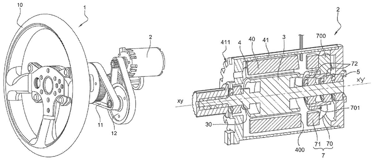
DETAILED DESCRIPTION The video game controller1shown inFIG. 1comprises a steering wheel10and a rotating electric motor2connected to the steering wheel10by a certain number of pulleys12and belts11. The electric motor2shown inFIG. 2comprises a rotor3integral with a shaft30of axis xx′ and a stator4with a winding40mounted on a casing41. The shaft30extends through the casing41. The shaft30has two ends (first and second ends). A steering wheel10is coupled to the first end (left end as viewed inFIG. 1). In the framework of this description, it shall be considered that the rotor and the stator of the motor can be inverted without leaving the scope of this invention. As such, in an electric motor, the coils can be fixed with respect to the casing and the magnet or magnets can be mobile with respect to the casing, and inversely. The references of each one can therefore be inverted in the claims. The casing41comprises a substantially cylindrical inside space wherein are arranged the rotor3and the stator4; and the casing41concentrically supports them and maintains them coaxial. The shaft30and the casing41are connected by bearings5allowing for a rotation of one with respect to the other. In the first embodiment ofFIGS. 2 and 3, the fan7includes a set of blades70and its own winding71integral with the casing41of the electric motor2(i.e. the coils of the fan7are fixed with respect to the casing41). The fan7is concentrically supported by the rotor3. The fan7is rotatably axially supported by the shaft30of the motor. The set of blades70is connected to the shaft30by bearings72in order to be able to rotate freely about said shaft30. The fan7is borne by the rotor3and is mobile in rotation about the yy′ axis with respect to the rotor3. Accordingly, the fan7has only one degree of freedom in rotation with respect to the rotor3and one degree of freedom in rotation with respect to the stator4too. The ...
DETAILED DESCRIPTION
The video game controller1shown inFIG. 1comprises a steering wheel10and a rotating electric motor2connected to the steering wheel10by a certain number of pulleys12and belts11.
The electric motor2shown inFIG. 2comprises a rotor3integral with a shaft30of axis xx′ and a stator4with a winding40mounted on a casing41.
The shaft30extends through the casing41. The shaft30has two ends (first and second ends). A steering wheel10is coupled to the first end (left end as viewed inFIG. 1).
In the framework of this description, it shall be considered that the rotor and the stator of the motor can be inverted without leaving the scope of this invention. As such, in an electric motor, the coils can be fixed with respect to the casing and the magnet or magnets can be mobile with respect to the casing, and inversely. The references of each one can therefore be inverted in the claims.
The casing41comprises a substantially cylindrical inside space wherein are arranged the rotor3and the stator4; and the casing41concentrically supports them and maintains them coaxial. The shaft30and the casing41are connected by bearings5allowing for a rotation of one with respect to the other.
In the first embodiment ofFIGS. 2 and 3, the fan7includes a set of blades70and its own winding71integral with the casing41of the electric motor2(i.e. the coils of the fan7are fixed with respect to the casing41). The fan7is concentrically supported by the rotor3. The fan7is rotatably axially supported by the shaft30of the motor. The set of blades70is connected to the shaft30by bearings72in order to be able to rotate freely about said shaft30. The fan7is borne by the rotor3and is mobile in rotation about the yy′ axis with respect to the rotor3. Accordingly, the fan7has only one degree of freedom in rotation with respect to the rotor3and one degree of freedom in rotation with respect to the stator4too. The fan7has no degree of freedom in translation with respect to the rotor3. The set of blades70comprises magnets701and blades700. Here the axis of the fan yy′ is coaxial with the axis xx′, but it can have a slight inclination with respect to the latter.
The air is forced to circulate to winding71of said fan7. The blades700of the set of blades70radially extend beyond the magnets701in such a way as to at least partially cover the winding71in order to improve the cooling therein and in order to have a blade surface that is as large as possible in order to optimise the cooling of the set of coils40and71.
The casing41has openings412at one of its axial ends and vents411at its other axial end. The openings and the vents are distributed at regular intervals radially with respect to the axis xx′. The blades700are arranged between the openings412and the winding71.
In this embodiment, the outside air is sucked by the fan7(arrows E) into the openings412, then sent to the winding71of the fan, circulates between the winding71of the fan, then circulates between the winding40of the motor, and exits via the vents411(arrows C).
The cooling can be done either by rotating the fan7permanently in order to permanently cool the motor and/or by changing its speed when the temperature of the motor measured by a temperature sensor (not shown) reaches a predetermined value, or by turning it on when the temperature of the motor reaches a predetermined value.
On the second embodiment ofFIG. 4, the motor (2) of the first embodiment has a fan6and the casing41is provided with a lateral opening410. The opening410is arranged radially with respect to the axis xx′. This opening410is preferably located in the vicinity of an end of the motor2, or of a winding head400. Here, the casing41has no opening412at one of its axial end (however it has vents411at its other axial end).
The fan6on an axis of rotation zz′ is connected to the casing41radially and facing the opening410, i.e. the axis zz′ is substantially orthogonal to the axis xx′. Here, the fan6is arranged under the casing in a box60and comprises blades61. The box60is fixed to the casing41by screws for example.
The casing41also has vents411arranged at the other axial end of the casing with respect to the opening410and distributed at regular intervals radially with respect to the axis xx′.
In this embodiment, the outside air will be sucked by the fan6(arrows E) which will send it to the opening410then to the set of coils40and exit via vents411(arrows C).
In the second embodiment, the cooling can be done either by rotating one or more of the fans (6,7) permanently in order to permanently cool the winding of the motor (2) and/or by changing their respective fan speed when the temperature of the motor measured by one or more temperature sensors (not shown) reach predetermined value(s), or by turning the fan(s) on when the temperature of the motor reaches a predetermined value.
In each of the two embodiments, the fan(s) can be controlled using the measurement of the current consumed by the motor. Indeed, the higher the current consumed is, the higher the thermal power to be dissipated will be. The current consumed by the motor is measured by a current sensor (not shown). The speed of rotation of the fan(s) can as such be controlled according to the current consumed by the motor. When the current consumed by the motor increases, an increase in the internal temperature of the motor is anticipated and consequently the speed of rotation of the fan(s) is (are) increased. The measurement of the current is taken by using a current sensor (a resistance or a Hall effect sensor).
The fan(s) can finally be controlled using the angular measurement of the steering wheel, and the calculation of the speed of the motor. The speed of rotation of the fan can as such be controlled by the speed of the motor. The faster the motor rotates, the slower the fan(s) rotate(s); inversely, the slower the motor rotates, the faster the fan(s) rotate(s).
Any of the types of fans may be used. For example, the fan(s) can be axial-flow fan(s), or radial-flow fan(s) (radial-flow fans are sometimes called centrifugal fans), or cross-flow fan(s).
In case of a radial fan, the casing41has openings arranged radially with respect to the axis yy′, instead of the (longitudinal) openings412. These openings radially face the blades of the fan.
The fan7can be located at different position longitudinally on the axis yy′ (which is coaxial with the axis xx′), for example near the back end of the motor i.e. at the side opposite to the pinion (as shown onFIG. 5) or near the front end of the motor (i.e. near the side where is the pinion). The fan can be arranged at either side with respect to the coils of the motor.
FIG. 5is a diagram of one embodiment of a system for a simulation or video game with a video game controller according to the invention. In one embodiment, the video game controller1may be connected to a computer system or console device503. The connection may be a wireless connection or may be a wire line connection. The wireless system may include a transmitting device within the video game controller1and a receiving device507attached to the computer or console or within the computer or console. A wire line system may use a specialized system or a general standard system such as a USB connection. The computer system may be any personal computer system, workstation or similar system. The system may be a console device such as a Sony, Microsoft, or Nintendo console or similar system. The computer system or console device may be connected to a monitor device such as a television505, LCD display or similar display device.
FIG. 6shows a simplified structure of a video game controller (1) according to the invention.
In one embodiment, the video game controller (1) may include a set of input mechanisms (A). The input mechanisms may include any number of buttons. The input mechanisms may include a cross pad, ministick or similar directional input mechanisms. The game controller (1) may have any number of input mechanisms and any configuration of types of input mechanisms (A).
The input/output module (I) receives internal input signals from the input mechanisms either directly or through microcontroller (μc). The input/output module (I) transforms the internal signals into signals that can be transmitted over a wire or wirelessly to the associated computer system or console device. In one embodiment, the input/output module (I) may transmit a wireless signal to a receiver attached to the console device or computer system. In another embodiment, the input/output module (I) may drive a signal or set of signals over a wire or set of wires to a specialized input port on a console or computer system. In a further embodiment, the input/output module may drive a signal or set of signals over a standard communications system such as a universal serial bus (USB) or similar system to a computer system or console device.
The input/output module (I) receives internal input signals from a rotation sensor (S1) either directly or through microcontroller (μc). The input/output module (I) transforms the internal signals into signals that can be transmitted over a wire or wirelessly to the associated computer system or console device.
In one embodiment, the input/output module (I) may transmit a wireless signal to a receiver attached to the console device or computer system. In another embodiment, the input/output module (I) may drive a signal or set of signals over a wire or set of wires to a specialized input port on a console or computer system. In a further embodiment, the input/output module may drive a signal or set of signals over a standard communications system such as a universal serial bus (USB) or similar system to a computer system or console device.
The input/output module (I) may receive information from an associated computer system or console device. The input/output module (I) may be a receiver for a wireless system or wired system. Information received from the computer system or console may be to direct the operation of the Feedback module via the microcontroller (μc) which embeds a data processing unit and a data storage unit. The feedback module (F) may be a circuit or similar system for driving the motor (2) such as a pulse width modulated (PWM) motor or similar device to generate a feedback sensation to a user. The feedback may be generated in response to the state of the current software application.
In one embodiment, the game controller (1) may include a set of light emitting diodes (LEDs) or similar devices. The LEDs (L) may be utilized to indicate the reception of input from input mechanisms. The LEDs (L) may be used to back-light or retro-light buttons for playing in dark areas. An LED may be activated in a flashing pattern to indicate an increase of heat when the user opposes to the rotation of the wheel of the game controller under the forces caused by the motor (2).
In one embodiment, the game controller (1) may include a fan (7) or a set of fans (6,7) for cooling the motor (2).
The microcontroller (μc) may receive information from one or more sensors (S1, S2, S3) to determine the heat in the casing of the motor (2) and/or in the shell of the game controller (1) which surrounds a portion of the game controller which is fixed in rotation (such portions including the motor (2), and,—if any—means (11,12) for transmitting rotational movements generated by the motor to the wheel10). Information received from the sensors may be to direct the operation of the fans (6,7). The fans may be activated or their speed increased selectively in response to an actual or anticipated increase of heat.
In the foregoing specification, the invention has been described with reference to specific embodiments thereof. It will, however, be evident that various modifications and changes can be made thereto without departing from the broader spirit and scope of the invention as set forth in the appended claims. The specification and drawings are, accordingly, to be regarded in an illustrative rather than a restrictive sense.
Claims
- A method for cooling an electric motor of a video game controller, the electric motor comprising a casing defining an interior motor space, a rotor and a number of motor coils positioned in the interior motor space, wherein the method comprises a forced air circulation between the motor coils, by a fan which is positioned in the interior motor space of the casing, and which is supported by the rotor and is mobile in rotation with respect to the rotor, in such a way that the speed of rotation of the fan is independent from the speed of rotation of the rotor.
- The method according to claim 1 , wherein the fan rotates at a substantially constant speed of rotation.
- The method according to claim 1 , wherein a current sensor measures the current consumed by the electric motor and the current determines the speed of rotation of the fan.
- The method according to claim 1 , wherein the motor coils are spaced to form cooling ducts for the forced air circulation.
- The method according to claim 1 , wherein the air also circulates between fan coils.
- The method according to claim 1 , wherein the air circulates in cooling ducts which are arranged between motor coils and are arranged substantially at the same distance of the axis xx' and in directions which are substantially parallel to the axis xx'.
- The method according to claim 1 , wherein at least one additional fan kinetically decoupled from the rotor is arranged on the casing of the electric motor.
- The method according to claim 7 , wherein the casing has at least an opening for the entry of air and at least one additional fan forces the entry of air to inside of the casing through the opening.
- The method according to claim 8 , wherein the casing has another opening for the escape of air and another fan forces the escape of air from the casing through the another opening.
- A video game controller having a motor comprising a main motor rotor which is mobile in rotation about an axis xx' with respect to a casing, and a fan mobile in rotation about an axis yy', wherein the fan is arranged on the main motor rotor, into the casing, in that the fan is coaxial with the main motor rotor, and in that the fan is mobile in rotation with respect to the main motor rotor.
- The video game controller according to claim 10 , wherein the main motor rotor bears the fan and in that the main motor rotor extends from the interior of the motor at both sides of the casing.
- The video game controller according to claim 11 , wherein one end of the main motor rotor is directly or indirectly connected to a steering wheel and the rotation of the other end of the main motor rotor is sensed by a rotation sensor.
- The video game controller according to claim 10 wherein the fan comprises a winding and an opening is arranged in the casing in vicinity of the winding of the fan.
- The video game controller according to claim 10 , wherein a fan rotor is connected to the axis xx' by a ball bearing.
- The video game controller according to claim 10 , wherein at least one additional fan kinetically decoupled from the main motor rotor is arranged at the bottom of the casing.
- The video game controller according to claim 10 , wherein at least one additional fan kinetically decoupled from the main motor rotor is arranged at the top of the casing.
- The video game controller according to claim 10 , wherein at least two additional fans kinetically decoupled from the main motor rotor are arranged on the casing.
- A method for cooling an electric motor of a video game controller when the motor converts electrical energy into a mechanical couple to tend to cause rotation of a main rotor about an axis xx' and exterior forces substantially oppose to such rotation, the motor having a casing having an opening for entry of sucked air wherein the method comprises a forced air ventilation from the outside of the casing to the inside of the casing, and a forced longitudinal circulation of air between coils of the motor, by at least one fan inside the casing, which is supported by the main rotor and rotatably movable with respect to the main rotor about an axis yy' which is coaxial with the axis xx'.
- The method according to claim 18 wherein blades of the fan radially extend beyond a magnet of the fan at least as much as the coils radially extend, in such a way to optimise the cooling of the coils.
- The method according to claim 18 wherein the main rotor and the fan rotor are coaxial.
Disclaimer: Data collected from the USPTO and may be malformed, incomplete, and/or otherwise inaccurate.