U.S. Pat. No. 10,441,874
ELECTRONIC GAME BOARD SYSTEM COMMUNICATING AT LEAST ONE GAME-PLAY-DATA
AssigneeIndividual
Issue DateJanuary 23, 2015
Illustrative Figure
Abstract
Disclosed is an electronic game board system communicating at least one game-play-data to an external device. The system includes a contactless communication unit (CCU), an electronic game board and one or more play items. The contactless communication unit communicates with the external device, and further provides alternating electric field. The electronic game board includes plurality of the play fields to receive the alternating electric field, wherein the playfields serially interconnected with each other. The play item capacitively transmits the game play data to the contactless communication unit. The contactless communication unit generates a processed-game-play-data defining a status of the play item placed on the play field, and the contactless communication unit further transmits the processed-game-play-data to the external device.
Description
The foregoing summary, as well as the following detailed description of certain embodiments of the present invention, will be better understood when read in conjunction with the appended drawings. For the purpose of illustrating the invention, certain embodiments are shown in the drawings. It should be understood, however, that the present invention is not limited to the arrangements and instrumentality shown in the attached drawings. DETAILED DESCRIPTION OF THE INVENTION While this technology is illustrated and described in a preferred embodiment, electronic gaming system may be produced in many different configurations, forms and materials. There is depicted in the drawings, and will herein be described in detail, as a preferred embodiment of the invention, with the understanding that the present disclosure is to be considered as an exemplification of the principles of the invention and the associated functional specifications for its construction and is not intended to limit the invention to the embodiment illustrated. Those skilled in the art will envision many other possible variations within the scope of the technology described herein. Reference will now be made in detail to several embodiments of the invention which are illustrated in the accompanying drawings. Wherever feasible and convenient, the same reference numerals are used in the figures and the description to refer to the same or like parts. The drawings are in a simplified form and not to precise scale. For purposes of convenience and clarity only, directional terms, such as top, bottom, left, right, up, down, over, above, below, beneath, rear, and front may be used with respect to the accompanying drawings. These and similar directional terms should not be strictly construed to limit the scope of the invention. In addition, words such as attached, affixed, coupled, connected and similar terms with their inflectional morphemes are used interchangeably, unless the ...
The foregoing summary, as well as the following detailed description of certain embodiments of the present invention, will be better understood when read in conjunction with the appended drawings. For the purpose of illustrating the invention, certain embodiments are shown in the drawings. It should be understood, however, that the present invention is not limited to the arrangements and instrumentality shown in the attached drawings.
DETAILED DESCRIPTION OF THE INVENTION
While this technology is illustrated and described in a preferred embodiment, electronic gaming system may be produced in many different configurations, forms and materials. There is depicted in the drawings, and will herein be described in detail, as a preferred embodiment of the invention, with the understanding that the present disclosure is to be considered as an exemplification of the principles of the invention and the associated functional specifications for its construction and is not intended to limit the invention to the embodiment illustrated. Those skilled in the art will envision many other possible variations within the scope of the technology described herein.
Reference will now be made in detail to several embodiments of the invention which are illustrated in the accompanying drawings. Wherever feasible and convenient, the same reference numerals are used in the figures and the description to refer to the same or like parts. The drawings are in a simplified form and not to precise scale. For purposes of convenience and clarity only, directional terms, such as top, bottom, left, right, up, down, over, above, below, beneath, rear, and front may be used with respect to the accompanying drawings.
These and similar directional terms should not be strictly construed to limit the scope of the invention. In addition, words such as attached, affixed, coupled, connected and similar terms with their inflectional morphemes are used interchangeably, unless the difference is noted or made otherwise clear from the context. These words and expressions do not necessarily signify direct connections, but include connections through mediate components and devices.
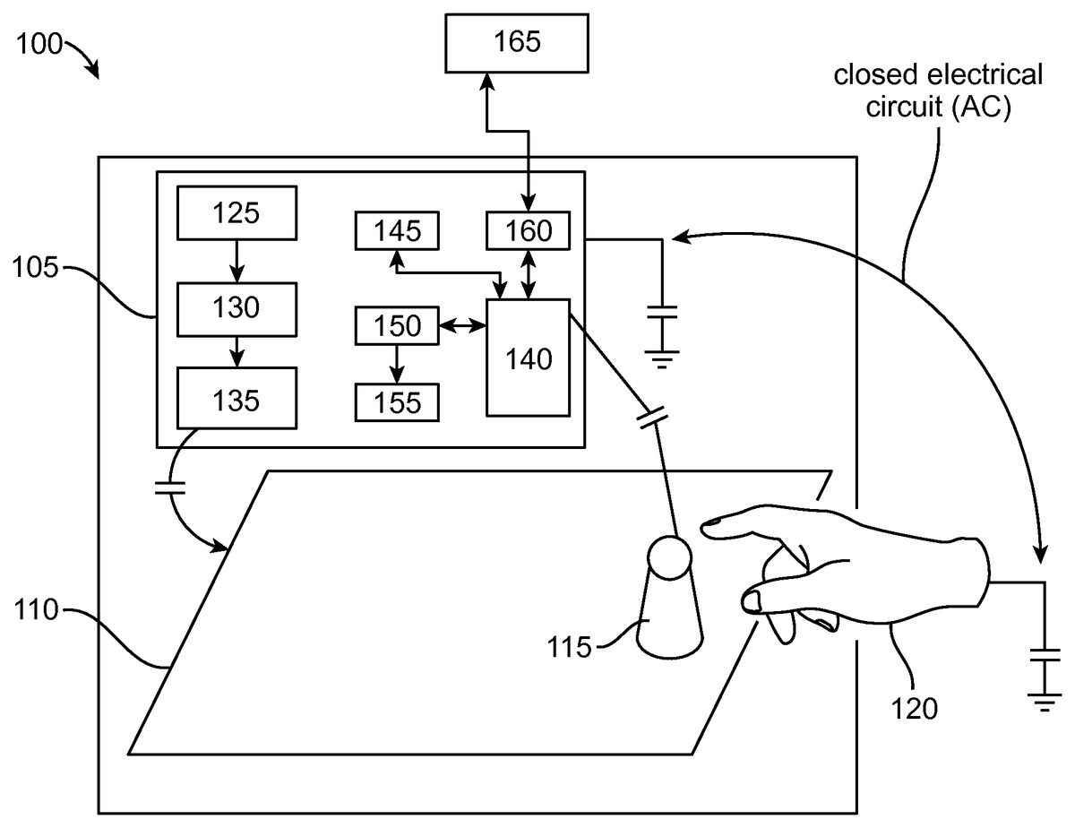
FIG. 1Aillustrates network architecture of an electronic game board system100communicating at least one game-play-data to an external device165. The system100includes a contactless communication unit105, an electronic game board110, and one or more play items115. The contactless communication unit105communicates with the external device165, and further provides alternating electric field. The electronic game board110having plurality of the play fields to receive the alternating electric field. Examples of the external device165may include but not limited to mobile phone, TV, personal computer, portable computer including laptop computer and notebook computer, and personal digital assistant.
The play fields are serially interconnected with each other. The play items115capacitively transmits the game-play-data to the contactless communication unit105. The contactless communication unit105generates a processed-game-play-data defining a status of the play item115placed on the play field. Further, the contactless communication unit105transmits the processed-game-play-data to the external device165. The play fields are explained in detail in conjunction with theFIG. 1B.
The contactless communication unit105includes a generator125, a first converter130, a first electrode135, an interface140, a memory unit145, a controller unit150, and a wireless transceiver unit160. The generator125receives power from a DC source for generating a low level alternating voltage. Examples of the generator125includes but not limited to an oscillator, a thermoelectric generator, and electromagnetic coils. The first converter130shifts the low level alternating voltage received from the generator125to a high level alternating voltage.
Example of the first converter130includes but not limited to a level shifter. However, it will be readily apparent to those with ordinary skill in the art that the various other types of the generator125and the first converter130may also be used for generating electric voltage and shifting the alternating voltage, respectively without deviating from the scope of the present invention.
The first electrode135is connected to the first converter130for emitting high level alternating electric field of specific frequency. Examples of the first electrode135includes but not limited to a conductive surface. The memory unit145stores a reference data associated with the play items115and the electronic game board110. The surface information, position information and identification information of the play item115are stored as the reference data. Examples of memory unit145includes but not limited to SD Flash ROM, memory card and other similar devices.
The interface140receives the game-play-data from the play item115caused by the user interaction. The interface140receives the plurality of game-play-data in the form of an analog signal and further converts the received analog signal into a digital signal i.e. digitized game-play-data. Example of interface140includes but not limited to electronic switches, analog to digital conversion (ADC) and digital to analog conversion (DAC).
The controller unit150processes the game-play-data received from the interface140by comparing the reference data with the game-play-data. In the preferred embodiment of the present invention, the controller unit150may be a finite state machine which may be implemented as hardware or a software running on a processor or combinations of the two. The finite state machine provides the condition/status of the play item115based on the progression of the game play performed by the user120.
FIG. 1Billustrates the play item115placed on the electronic game board110communicating with the contactless communication unit105, in accordance to the present invention. The play item115includes a second electrode205i.e. conductive electrode, a floating electrode210, a second converter215, a buffer220, a detection unit225and a modulator230.
The second electrode205i.e. conductive electrode receives the alternating electric field emitted from the first electrode135, and further receives the gesture signal of the user120. The floating electrode210floats the electric field received from the first electrode135to the ground, so as to form a closed electric circuit with at least one of: the contactless communication unit105; and the user120. Examples of the second electrode205and the floating electrode210include but not limited to any conductive surface.
The second converter215converts the alternating voltage received from the second electrode205into a direct voltage. Example of the second converter215may be a rectifier, inductor, resonator, cascade, diode bridges, transformer, and level shifter. The buffer220stores the direct voltage received from the second converter215. Examples of the buffer220include but not limited to capacitor, and accumulator. As an example, a 5.5 V/1 F Panasonic “super capacitor” specifies a voltage drop at 20° C. from 5.5 V down to 3 V in 600 hours (25 days or 3.6 weeks) for a double cell capacitor.
The detection unit225detects the game-play-data associated with at least one surface information, the position information, and a first identification information of the play item115. The detection unit225detects the game-play-data when the closed electrical circuit is formed in between the play item115and the user120. The detection unit225is explained in detail in conjunction with theFIG. 2BandFIG. 2Cof the present invention.
The modulator230modulates the alternating electric field influenced by the first electrode140with the detected data, and further transmits the modulated data to the interface140. The controller unit150receives the modulated data and further processes the modulated data based on the reference data stored in the memory145. The signal transmitted by the modulator230may be modulated using any modulation technique.
Examples of the modulation technique include but not limited to analog modulation such as AM, FM, PM, QAM, SM, digital modulation such as ASK, APSK, CPM, FSK, MFSK, MSK, OOK, PPM, PSK, QAM, SC-FDE, TCM and spread spectrum such as CSS, DSSS, FHSS, THSS. The entire electric circuitry such as the second electrode205, the floating electrode210, the second converter215, the buffer220, the detection unit225, and the modulator230of the play item115may be embedded in a single chip or in a printed decal or on a flexible polymer foil.
The controller unit150outputs the processed game-play-data to define the status of the play item115. The wireless transceiver160is bi-directionally communicating the processed-game-play-data to the external device165. The processed-game-play-data defining the image of the play item115and the electronic game board110is displayed in the external device165. Examples of wireless transceiver unit116include but not limited to Bluetooth, Wi-Fi, Ethernet, frame relay, devices supporting ATM/SONET and devices supporting internet protocols.
In another preferred embodiment of the present invention, the display unit155displays the processed-game-play-data defining the status of the play item115. Example of display unit155includes but not limited to touch panel screen of the mobile phone, LED display, OLED display, and other similar display devices.
In another preferred embodiment of the present invention, the system100further includes a bi-directional player communication unit (PCU)300integrated to a wearable article305such as a wristband of the user120for communicating with the contactless communication unit105, in accordance with the present invention.
The player communication unit (PCU)300transmits the second identification information and gesture information associated with the user120and further receives the command data signalizing the status of the play item115from the controller unit150through the interface140. Thus, the player communication unit300works bi-directionally. Examples of the wearable articles305include but not limited to an ear-plug, a headband, a glove, a ring, and a clip attachable to the user120. The user120is identified as anonymous user, when the user120initiates the game play without any player communication unit300.
The second identification information indicates the identity information of the user120for enabling the contactless communication unit105to identify the user120. The gesture information indicates the user location and the user proximity relative to the play item115placed on the play field200a. The detection of the second identification information and gesture information is explained in detail in conjunction with theFIG. 2Bof the present invention.
In the preferred embodiment of the present invention, the plurality of the play fields202are positioned along the outer peripheral edges of the electronic game board110. The play fields202are the conductive traces that receive the alternating electric field emitted from the first electrode140. The electric field is bridged in between the PCU300and the play field202to detect the gesture information of the user120.
The PCU300includes an electronic circuitry that is similar to that of the circuitry incorporated in the play item115. The PCU300further transmits the detected second identification information and gesture information associated with the user120to the interface145. The controller unit150determines the user's identity and user's gesture based on the reference data stored in the memory unit160. For example, from the gesture information, the CCU105identifies whether the user120approaches the play item115from the north direction or south direction or east direction or west direction.
In another preferred embodiment of the present invention the PCU300is integrated with a wearable article such as the ear-plug. For example, the PCU300transmits the second identification information indicating identified-user as e.g. Tom and the user's gesture information as “Tom approaching the play item115from east direction of the game board”. The CCU105sends the command data associated with the play item115and the user to the PCU300. The ear-plug integrated to the PCU300plays an audio signal to signalize the user information as “Tom” and the user's gesture information as “Tom approaching the play item115from east direction of the game board”.
FIG. 2Aillustrates the network architecture of the one or more play items115a,115b,115cplaced on the playfields200a,200b, and200crespectively, and communicating with the contactless communication unit105. The electronic game board110further includes printed lines204to indicate connectivity between the one or more playfields200a,200b, and200c.
In an exemplary embodiment, the voltage ratio of the play item115aplaced on the first playfield200ais 99% and the voltage ratio of the play item115cplaced on the last playfield200cis 1%. The detection of voltage ratio of the play item115to the play field200is explained in detail in conjunction withFIG. 2C.
As shown, the play items115, such as pawns115a,115c, and dice115bhaving surface S1-S3 (Visible), S4-S6 (not shown inFIG. 2A). However it is readily apparent to those skilled in the art that various play items115such as action figures, play stones, play cards, dice, miniatures (houses in monopoly) may be envisioned without deviating from the scope of the present invention. For example, the dice115bhaving 6 surfaces (as shown inFIG. 2A), one or more second electrodes E are arranged along the respective surfaces S1-S6 of the play item115b.
In the preferred embodiment of the present invention, the dice surface S4 is in contact with the play field200b. When the dice surface S4 is in contact with the play field200bthen the electric field strength in between the play field200band the electrode E2 integrated with the dice surface S4 is greater. Hence, the dice115bis detected to be closer to the play field200b. Similarly, the play item115ais detected closer to the play field200a, and the play item115cis detected closer to the play field200c.
FIG. 2Billustrates the circuitry of the detection unit225to detect the surface of the play item115in contact with the play field200b. In the preferred embodiment of the present invention, the play item115is a dice with multiple surfaces, wherein at least one detection unit225is attached to the second electrodes of the play item115.
For exemplary purposes, the play item115has six detection units225a-225fattached to the second electrodes E1-E6 at the surfaces S1-S6 of the play item115respectively. The detection unit225aincludes a first Schmitt trigger ST1, a second Schmitt trigger ST2, and a counter L1. The first Schmitt trigger ST1 generates a clock signal on receiving an analog input which is the alternating voltage of the second electrode E1 at surface S1 of the play item115.
The second Schmitt trigger ST2 generates a pulse signal having time interval associated with the electric field strength in between the second electrode E1 of the play item115and the play field200b. The counter L1 e.g. D-flip flop counter is connected to the first Schmitt trigger ST1, and the second Schmitt trigger ST2. The counter L1 counts the digital value that represents the electric field strength in between the play field200band the second electrode E1 of the play item115.
Similarly, the other detection units225b-225foutput the digital value that represents the electric field strength in between the play field200band the second electrodes E2-E6 of the play item115respectively.
The modulator (not shown inFIG. 2B) receives the digital value from the counter L1-L6, and further sends the modulated digital code to the controller unit (not shown inFIG. 2B) through the interface (not shown inFIG. 2B). The controller unit detects the orientation of the play item115on the play field200b. In a preferred embodiment of the present invention, the display unit (not shown inFIG. 2B) or the external device (not shown inFIG. 2B) further displays the top surface of the play item115on the play field200b.
For an example, the dice surface S1 is having one spot representing a dice-thrown-value as one, the dice surface S2 is having two spots representing a dice-thrown-value as two, the dice surface S3 having three spots representing a dice-thrown-value as three, the dice surface S4 having four spots representing a dice-thrown-value as four, the dice surface S5 having five spots representing a dice-thrown-value as five, and the dice surface S6 having six spots representing a dice-thrown-value as six.
For exemplary purposes the digital output of the detection units225a-225fin contact with the play field200bare shown in the below table1. The counter output L1-L6 versus various conditions associated with the play item115is illustrated in the below table.
L1L2L3L4L5L6CounterDice-o/po/po/po/po/po/pO/P (L1-thrownat S1at S2at S3at S4at S5at S6L6)valueCondition 1:1000001000006S1in contactwith playfieldCondition 2: S20100000100004in contact withplayfieldCondition 3: S30010000010005in contact withplayfieldCondition 4: S40001000001002in contact withplayfieldCondition 5: S50000100000103in contact withplayfieldCondition 6: S60000010000011in contact withplayfield
When the dice surface S1 is in contact with the play field200b, the dice surface S6 is on the top. The controller unit identifies the top dice surface S6 is oriented opposite to the dice surface S1 based on the digital code (100000) as illustrated in the above table. The controller unit outputs the surface information indicating a dice-throw-value as 6 and the identity of the play item115as dice to signalize the status of the thrown play item115. The display unit (not shown inFIG. 2B) displays the dice surface S6 having six spots to signalize the status of the thrown play item115.
In other preferred embodiment the detection unit225includes a shift register to receive the digital value from the counter L1-L6, when the dice surface S1 is in contact with the play field200. The shift register further shifts the digital output into a digital code e.g. Manchester code indicating at least one of the identification number and the surface information of the play item115.
FIG. 2Cillustrates the detection unit225for detecting the position of the play item115. The contactless communication unit (not shown inFIG. 2C) stores the reference data associated with the position information P1-P6 of the play fields200. The playfields200function as serial capacitance C1-C6 to feed the electric field in from all sides of the play item115. The playfields at position P1-P6 may be arranged in any matrix-free linear format.
The detection unit225measures voltage ratio of the one or more second electrodes of the play item115to the play field200. The detection unit225detects the position of the play item115placed on the position P4 of the play field200based on the voltage ratio of the play item115.
The voltage ratio is calculated by the following formula:
Position information=voltage ratio of the play item 115=(R1×I1)/(R2×I2),
Where,R1=resistance value at the resistor connected to position P1 of the first play field;I1=current value across the resistance R1 connected to position P1 of the first play field;R2=resistance value at the resistor connected to position of the last play field;I2=current value across the resistance R2 connected to position n+1 of the last play field.
For example, the user120moves the play item115to different positions such as P4, P5 and P6 during the game play. Then the voltage ratio of the play item115is 70% at the position P4, the voltage ratio of the play item115is 50% at the position P5, and the voltage ratio of the play item115is 30% at the position P6. The detection unit225transmits the detected position information of the play item115to the interface of the contactless communication unit (not shown inFIG. 2C).
Further the controller unit (not shown inFIG. 2C) processes the game-play-data associated with the position information of the play item115. The controller unit outputs the position information of the play item115as P4. In the preferred embodiment of the present invention, the display unit (not shown inFIG. 2C) or the external device (not shown inFIG. 2C) displays a visual indica of the play item115at the position P4 of the play field200.
FIG. 3illustrates the formation of closed electrical circuit in between the play item115and the user120. The play item115further includes an optical unit235to generate an optical signal for signaling the status of the play items115. Example of the optical unit include but not limited to a light emitting diode, neon lights etc. The status of the play items115is explained in detail in conjunction with theFIG. 2AandFIG. 2Bof the present invention.
The optical unit235illuminates the light upon the gesture/proximity information of the user120detected by the detection unit (not shown inFIG. 3). In the preferred embodiment of the present invention, if the play item115is approached by the user, then the optical unit235illuminates the light with low intensity. If the play item115is touched by the user, then the optical unit235illuminates the light with high intensity.
In another preferred embodiment of the present invention, the play item115further includes a vibration unit to cause a vibration signal for signaling the status of the play items, and an audio unit to generate an audio signal for signaling the status of the play items. Example of the vibration unit includes but not limited to a piezoelectric vibrator, and example of the audio unit includes but not limited to a speaker.
FIG. 4illustrates the flow chart illustrating the electronic gaming method400for communicating game-play-data to at least an external device. The method400initiates with the step402of providing alternating electric field from a contactless communication unit (CCU) communicating with the external device. The step402is followed by a step404of receiving the alternating electric field by an electronic game board having plurality of the play fields serially interconnected with each other.
The step404is followed by a step406of transmitting the game-play-data from one or more play items to the contactless communication unit for generating a processed-game-play-data defining a status of the play item placed on the play field. The step406is followed by a step408of transmitting the processed-game-play-data from the contactless communication unit to the external device.
FIG. 5illustrates the electronic game system500communicating game-play-data in between the contactless communication unit (CCU)105and the one or more play items115, in accordance to other preferred embodiment of the present invention. The system500allows the user120to perform the game play by the CCU105, the play item115, and the player communication unit300. Example of the CCU105includes but not limited to a mobile phone, a smart phone, a phablet, a tablet and a smart watch.
The CCU105displays plurality of play fields200associated with a game, to perform a game play by the user120. The play item115are placed on the play fields200displayed on the contactless communication unit105. Further the play items115are capacitively coupled to the CCU105.
The play item115communicates the game-play-data to the interface (not shown inFIG. 5) of the CCU105when the play item115is moved on the play field200by the user120. In the exemplary embodiment, the user120is wearing a wearable article integrated with a player communication unit (PCU)300to transmit the second identification information and gesture information associated with the user120.
The controller unit (not shown inFIG. 5) of the CCU105processes the game-play-data received from the interface (not shown inFIG. 5). The controller unit further transmits the processed game-play-data such as surface information, the position information and the identification information of the play item115to the interface (not shown inFIG. 5).
In an exemplary embodiment of the present invention, the display unit (not shown inFIG. 5) or the external device displays the processed-game-play-data defining the status of the play item115received from the interface (not shown inFIG. 5). The features and function of the CCU105, the play item115, the player communication unit (PCU)300are explained in detail in conjunction with theFIG. 1AandFIG. 1B.
In this embodiment, the system500further includes an electronic game board (not shown inFIG. 5) to receive the alternating electric field from the CCU105. The play items115placed on the electronic game board transmit the game-play-data to the CCU105. The features and function of the electronic game board are explained in detail in conjunction with theFIG. 1A.
There has thus been shown and described the electronic gaming system and method for providing interactive game-play-data to at least an external device. Many changes, modifications, variations and other uses and applications of the subject invention will, however, become apparent to those skilled in the art after considering this specification and the accompanying drawings which disclose the preferred embodiments thereof. All such changes, modifications, variations and other uses and applications which do not depart from the spirit and scope of the invention are deemed to be covered by the invention, which is to be limited only by the claims which follow.
Claims
- An electronic game board system communicating at least one game-play-data to an external device, the system comprising: a contactless communication unit to communicate with the external device, and further to provide alternating electric field, wherein the contactless communication unit comprising;a generator to receive power from a DC source for generating a low level alternating voltage;a first converter to shift the low level alternating voltage received from the generator to high level alternating voltage;a first electrode connected to the first converter for emitting high level alternating electric field of fixed frequency;a memory unit to store reference data associated with each of the play item and the electronic game board;an interface to receive the game-play-data from the play item caused by the user interaction;a controller unit to process the game-play-data received from the interface by comparing the reference data with the game-play-data and further transmits the processed game-play-data to the interface;and a wireless transceiver to bi-directionally communicate the processed-game-play-data received from the controller unit to the external device;an electronic game board having plurality of the play fields to receive the alternating electric field, wherein the playfields serially interconnected with each other;and one or more play items capacitively transmits the game play data to the contactless communication unit for generating a processed-game-play-data defining status of the play item placed on the play field, wherein the contactless communication unit transmits the processed-game-play-data to the external device, wherein the external device processes, stores and displays the game play data.
- The system according to claim 1 , wherein the play item comprising: a second electrode to receive the alternating electric field emitted from the first electrode, and further receiving gesture signal of the user;a floating electrode to float the alternating electric field to the ground for forming a closed electric circuit with at least one of: the CCU;and the user;a second converter to convert the alternating voltage received from the second electrode to the direct voltage;a buffer to store the direct voltage received from the second converter;a detection unit to detect the game-play-data associated with at least one surface of the play item, position of the play item on the play field, and a first identification information of the play item;and a modulator to modulate the alternating electric field influenced by the first electrode with the detected data, and further transmits the modulated data to the interface.
- The system according to claim 1 , wherein the contactless communication unit comprising a display unit to display the processed-game-play-data defining the status of the play item.
- The system according to claim 1 , further comprising a bi-directional player communication unit (PCU) integrated with a wearable article of the user to communicate the second identification information and user-gesture-information with the controller unit through the interface.
- The system according to claim 2 , wherein the detection unit comprising: a first Schmitt trigger to generate a clock signal on receiving the alternating voltage of the second electrode;a second Schmitt trigger to generate a pulse signal having time interval associated with the electric field strength in between the play item and the play field;and a counter connected to the first Schmitt trigger and the second Schmitt trigger for generating a digital value indicating the surface information of the play item and the position information of the play item.
- The system according to claim 1 , wherein the controller unit further sends a command data to at least one of the play item;and the player communication unit (PCU) through the interface for signalizing the status of the play item.
- The system according to claim 1 , wherein the memory unit further stores the processed-game-play-data associated with the game play performed by the user.
- The system according to claim 2 , wherein the play item further comprising: an optical unit to generate an optical signal for signaling the status of the play items;a vibration unit to cause a vibration signal for signaling the status of the play items;and an audio unit to generate an audio signal for signaling the status of the play items.
- An electronic game board system communicating game-play-data over a communication network, the system comprising: a contactless communication unit communicating over a communication network to provide alternating electric field;an electronic game board having plurality of the play fields to receive the alternating electric field;and one or more play items capacitively coupled to the contactless communication unit, further the play items transmit the game-play-data to the contactless communication unit;wherein the contactless communication unit comprising: a generator to receive power from a DC source for generating a low level alternating voltage;a first converter to shift the low level alternating voltage received from the generator to high level alternating voltage;a first electrode connected to the converter for emitting high level alternating electric field of specific frequency;a memory unit to store reference data associated with the play item and the electronic game board;an interface to receive the game-play-data transmitted from the play item caused by the user interaction;a controller unit to process the game-play-data received from the interface by comparing the reference data with the game-play-data and further transmits the processed game-play-data to the interface;and a display unit to display the processed-game-play-data defining the status of the play item received from the interface;an electronic game board having plurality of the play fields to receive the alternating electric field, wherein the playfields serially interconnected with each other;and one or more play items capacitively coupled to the contactless communication unit, the play item comprising: at least a second electrode to receive the alternating electric field emitted from the first electrode, and further receiving the trigger signal from gesture of the user;a floating electrode to float the alternating electric field to the ground for forming a closed electric circuit with at least one of: the CCU;and the user;a second converter to convert the alternating voltage received from the second electrode to the direct voltage;a buffer to store the direct voltage received from the second converter;a detection unit to detect the game-play-data associated with at least one surface of the play item, position of the play item on the play field, and a first identification information of the play item;and a modulator to modulate the alternating electric field influenced by the first electrode with the detected data, and further transmits the modulated data to the interface.
- The system according to claim 9 , further comprising a bi-directional player communication unit (PCU) integrated with a wearable article of the user to transmit the second identification information and gesture information associated with the user.
- The system according to claim 9 , wherein the detection unit comprising: a first Schmitt trigger to generate a clock signal on receiving the alternating voltage of the second electrode;a second Schmitt trigger to generate a pulse signal having time interval associated with the electric field strength in between the play item and the play field;and a counter connected to the first Schmitt trigger and the second Schmitt trigger for generating a digital value indicating the surface information of the play item and the position information of the play item.
- The system according to claim 9 , wherein the controller unit further sends a command data to the play item and the player communication unit (PCU) through the interface for signalizing the status of the play item.
- The system according to claim 9 , wherein the memory unit further stores the processed-game-play-data associated with the game play performed by the user.
- The system according to claim 9 , wherein the play item further comprising: an optical unit to generate an optical signal for signaling the status of the play items;a vibration unit to cause a vibration signal for signaling the status of the play items;and an audio unit to generate an audio signal for signaling the status of the play items.
- The system according to claim 9 , wherein the play item further comprising a flexible polymer foil for embedding the second electrode, the floating electrode, the second converter, the buffer, the detection unit, and the modulator of the play item.
- An electronic game system communicating game-play-data, the system comprising: a contactless communication unit to display plurality of play fields associated with a game, and further to provide alternating electric field;one or more play items capacitively coupled to the contactless communication unit, further the play items transmit the game-play-data to the contactless communication unit;wherein the contactless communication unit comprising: a generator to receive power from a DC source for generating a low level alternating voltage;a first converter to shift the low level alternating voltage received from the generator to high level alternating voltage;a first electrode connected to the converter for emitting high level alternating electric field of specific frequency;a memory unit to store reference data associated with the play item;an interface to receive the game-play-data transmitted from the play item caused by the user interaction;a controller unit to process the game-play-data received from the interface by comparing the reference data with the game-play-data and further transmits the processed game-play-data to the interface;and a display unit to display the processed-game-play-data defining the status of the play item received from the interface;one or more play items placed on the play fields displayed on the contactless communication unit, the play item comprising: at least a second electrode to receive the alternating electric field emitted from the first electrode, and further receiving the trigger signal from gesture of the user;a floating electrode to float the alternating electric field to the ground for forming a closed electric circuit with at least one of: the CCU;and the user;a second converter to convert the alternating voltage received from the second electrode to the direct voltage;a buffer to store the direct voltage received from the second converter;a detection unit to detect the game-play-data associated with at least one surface of the play item, position of the play item on the play field, and a first identification information of the play item;and a modulator to modulate the alternating electric field influenced by the first electrode with the detected data, and further transmits the modulated data to the interface.
- The system according to claim 16 , further comprising a player communication unit (PCU) integrated with a wearable article of the user to transmit the second identification information and gesture information associated with the user, and further receives the command data signalizing the status of the play items from the controller unit through the interface.
- The system according to claim 16 , wherein the detection unit comprising: a first Schmitt trigger to generate a clock signal on receiving the alternating voltage of the second electrode;a second Schmitt trigger to generate a pulse signal having time interval associated with the electric field strength in between the play item and the play field;and a counter connected to the first Schmitt trigger and the second Schmitt trigger for generating a digital value indicating the surface information of the play item and the position information of the play item.
- The system according to claim 16 , further comprising an electronic game board to receive the alternating electric field;wherein the play items placed on the electronic game board transmit the game-play-data to the contactless communication unit.
Disclaimer: Data collected from the USPTO and may be malformed, incomplete, and/or otherwise inaccurate.