U.S. Pat. No. 10,427,038
GAME CONSOLE INCORPORATING BEAM-SPLITTER DISPLAY AND REAL WORLD OBJECTS
AssigneeToccata Gaming International, LLC
Issue DateJanuary 21, 2016
Illustrative Figure
Abstract
A game console having a beam splitter disposed in a housing and a projector that projects images onto the beam splitter that are reflected so that a player can see the images. Real world objects and/or additional projectors are positioned behind the beam splitter relative to the player and transmit images through the beam splitter so that the player can see them. In this fashion, during game play the player simultaneously sees images that are reflected from the beam splitter and images that are transmitted through the beam splitter.
Description
DETAILED DESCRIPTION The following definitions are used throughout the specification and claims: “Beam splitter” is used herein to designate a device of any configuration that divides a beam of light or other electromagnetic radiation into two or more separate beams. Beam splitters include prisms and various types of coated glass. Beam splitters, including coated beam-splitting glass that operates in the visual wavelengths is commercially available from a large number of suppliers, such as Edmund Optics (Barrington, N.J.). Beam-splitting glass is typically characterized by its percentage of reflectance (R) versus transmittance (T), the wavelength ranges for reflectance/transmittance, and whether it polarizes the reflected/transmitted image. Any beam splitter that operates in the visual wavelengths may be used in the present console. “Computer” as used herein means any electronic device that is specially and permanently programmed to generate digital images (still pictures, animation, motion pictures, alpha-numeric text, etc.), to generate sound, and to execute game code (either via software code, hardware-implemented code, firmware-implemented code, or any combination thereof) or any electronic device that can be programmed to generate the images and sounds and to execute the game code (again via software, hardware, firmware, or any combination thereof) needed to play an interactive video game, including (by way of example and not limitation), a single (or multiple) processor-based system that may be supported in a stand-alone (desktop, laptop, personal digital assistant, arcade console), networked, mainframe, or client-server architecture, or other computing environment. The system used may include one or more known storage devices (e.g., Random Access Memory (RAM), Read Only Memory (ROM), hard disk drive (HDD), floppy drive, tape drive, compact disk/write-read-ROM, DVD, bubble memory, flash memory, etc.), and may also include one or more memory devices embedded within a processor, or shared with one or more of the other components. The computer may ...
DETAILED DESCRIPTION
The following definitions are used throughout the specification and claims:
“Beam splitter” is used herein to designate a device of any configuration that divides a beam of light or other electromagnetic radiation into two or more separate beams. Beam splitters include prisms and various types of coated glass. Beam splitters, including coated beam-splitting glass that operates in the visual wavelengths is commercially available from a large number of suppliers, such as Edmund Optics (Barrington, N.J.). Beam-splitting glass is typically characterized by its percentage of reflectance (R) versus transmittance (T), the wavelength ranges for reflectance/transmittance, and whether it polarizes the reflected/transmitted image. Any beam splitter that operates in the visual wavelengths may be used in the present console.
“Computer” as used herein means any electronic device that is specially and permanently programmed to generate digital images (still pictures, animation, motion pictures, alpha-numeric text, etc.), to generate sound, and to execute game code (either via software code, hardware-implemented code, firmware-implemented code, or any combination thereof) or any electronic device that can be programmed to generate the images and sounds and to execute the game code (again via software, hardware, firmware, or any combination thereof) needed to play an interactive video game, including (by way of example and not limitation), a single (or multiple) processor-based system that may be supported in a stand-alone (desktop, laptop, personal digital assistant, arcade console), networked, mainframe, or client-server architecture, or other computing environment. The system used may include one or more known storage devices (e.g., Random Access Memory (RAM), Read Only Memory (ROM), hard disk drive (HDD), floppy drive, tape drive, compact disk/write-read-ROM, DVD, bubble memory, flash memory, etc.), and may also include one or more memory devices embedded within a processor, or shared with one or more of the other components. The computer may generate images and execute game code to play any interactive video game of any description, with or without accompanying sounds, music, haptic signals, and the like. The computer may be dimensioned and configured as one or more hardware modules, as one or more software modules, or any combination thereof.
“Controller” is defined broadly to mean any device dimensioned and configured for one or more human users to control game play in an interactive video game, including hardwired and wireless controllers, haptic feedback controllers, motion-sensing controllers and the like, whether now known or developed in the future, and of any configuration or input mechanism. Conventional controllers come in many configurations, all of which are included in the definition “controller.” For example, a gamepad or joypad controller is held in one or both hands and the thumb(s) and finger(s) are used to provide input. Gamepads can have a number of action buttons combined with one or more omnidirectional control sticks or buttons. Paddle controllers include a wheel and one or more action buttons, for example a “fire” or “shoot” button. Joystick controllers have a handheld stick that can be tilted around either of two axes and (optionally) twisted around a third. Joystick controllers are often used for flight simulators. Joystick controllers are sometimes combined with a throttle quadrant controller (see below) to yield a “hands-on throttle-and-stick” controller in which action buttons or switches are placed on the joystick itself, thus enabling the player to use the joystick and to execute other actions simultaneously, without having to remove their hands from the joystick. For example, in the context of a flight simulation game, the joystick is conventionally used to control the flight of the virtual aircraft, and buttons on the joystick are used to access other functions, such as releasing virtual bombs or firing virtual weapons. Trackball controllers are essentially an upside-down mouse that is manipulated with the palm and fingers of the players hands. A throttle quadrant controller includes a set of one or more levers that are most often used to simulate throttles or other similar controls in a real vehicle, particularly an aircraft. Throttle quadrants are most popular in conjunction with joysticks or yokes used in flight simulation or submarine simulation. Steering wheel controllers are analogous to the steering wheel of an automobile, and are simply a larger version of a paddle controller designed to emulate the look and feel of a terrestrial vehicle (car, truck, tank, etc.). They are often used in conjunction with foot controllers to emulate the accelerator, brake, and clutch pedals of a manual transmission racing car. Yoke controllers are similar, but are analogous to the yoke used in aircraft and function in the same fashion. Unlike steering wheel controllers, though, yoke controllers have two and sometimes three axes of movement (rotational, up/down/left/right, in/out). Keyboard and mouse combinations are widely used as controllers in games implemented on desktop computers. Touchscreen controllers allow the user to interact with the computer by touching a display screen. Motion sensing controllers interpret a player's physical movements to provide inputs to the gaming system. The Wii-brand controller, for example, uses accelerometers to detect its approximate orientation and acceleration, as well as and an image sensor that enables it to be used a pointing device (such as a virtual firearm). Microsoft's Kinect-brand controller for the Xbox-brand gaming systems uses cameras to track a player's movement. A light gun is a controller that uses a laser or other EM wave to “shoot” virtual targets on the game display. They are often configured to resemble modern or historic firearms or futuristic ray guns, blasters, and the like. Rhythm-type controllers are typically a combination of one or more of the controllers described above, but configured to resemble (and be operated akin to) a musical instrument such as a guitar. See, for example, the controllers described in U.S. Pat. Nos. 6,275,213 6,280,327; 6,285,379; 6,424,333; 6,850,221; 6,878,066; 8,537,231 and 8,986,125, all of which are incorporated herein by reference.
The term “operationally linked” or “operationally connected” means that two or more devices connected by a “linkage” are connected in such a fashion that the linked devices operate in the intended fashion. For example, a computer operationally linked to a projector is connected in such a fashion that digital signal stream encoding images generated by the computer is accurately decoded into an image and the image is projected by the projector. In the same fashion, a controller operationally linked to a computer is capable of controlling the play of the game being executed in code on the computer. The term “linkage” is used herein to designate any kind of operational link that connects the two or more stated devices in an operational fashion. Linkages may be hard wire linkages or wireless linkages of any configuration.
The terms “projector” and “image projector” are used synonymously and are broadly defined to encompass any device dimensioned and configured to project an image visible to the human eye. Included within the definition of “projector” are conventional, cathode ray tube (CRT) projectors, liquid crystal display (LCD) projectors, direct/back-lit and edge-lit light emitting diode (LED) projectors, and plasma displays. These are all conventional devices, well-known, and widely available worldwide from a huge host of manufacturers.
Turning now to the figures, the same reference numerals are used throughout the drawings to designate the same or analogous features in each view.FIG. 1is a side elevation schematic of a first version of the game console. The console includes an enclosure or housing10. The housing optionally includes a visually transparent front18, which may be made of a glass or a transparent plastic, for example, a polycarbonate, an acrylic such as poly(methyl methacrylate)), glycol-modified polyethylene terephthalate, and the like. The function of the front18is principally to keep dirt, grime and fingerprints off the beam splitter20(described below) and to provide structural rigidity to the housing10. The housing may also optionally include a visually transparent top16, made from the same materials. The top16may be omitted and the projector22, described below, incorporated directly into the housing10as its top surface. As shown inFIG. 1, the back12and bottom14of the housing may be made from any suitably strong material, such as metal, wood, particle board, etc. The back12may be fabricated from transparent materials as well. Left and right sides, not shown inFIG. 1, may be fabricated from the same materials.
Disposed within the housing, at substantially a 45° angle, is a beam splitter20. The beam splitter20may be standard plate glass. However, to convey a crisp, clear image to the user, it is preferred that the beam splitter20be a sheet of coated, beam-splitting flat glass having a transmittance/reflectance (T/R) ratio of from about 20/80 to about 80/20, without about 60/40 to about 50/50 generally preferred.
Disposed on top of the housing10is a projector22, of conventional design. The projector22is operationally connected by linkage42to a processor or computer24. The computer24encodes the video game being played on the console. The computer24contains and executes the programming of the game being played and generates a digital signal train that encodes game images, sounds, scoring, etc., in conventional fashion. The digital signal train encoding the images is output to the projector22via the linkage42and the projector converts the signals into projections or projected images designated by arrows28. The projector22is located in such a fashion that the projected images28impinge upon the beam splitter20, and are reflected so that a user/player100can see them. The reflected images seen by the user are shown inFIG. 1by arrows30,32,34, and36.
Because of the T/R ratio of the beam splitter20, the player100, when looking at the beam splitter as shown inFIG. 1, sees both the reflected images30,32,34, and36, generated by the projector22, as well as the transmitted image of the back of the enclosure12. Thus, the back12, may have disposed upon it graphics, images, etc., which will be viewable by the player100. Alternatively, the back12, may be a second projector operationally connected to the computer24, as shown by dashed linkage45. If the back12is a second projector, the player100simultaneously sees the images30,32,34,34reflected from the beam splitter20, and the transmitted images from the back12that pass through the beam splitter20.
Disposed within the housing, on the back side of the beam splitter20(i.e., on the other side of the beam splitter relative to the player100) is at least one award indicator40′. The award indicator may be a stand-alone unit or may be a retractable unit housed within enclosure38. As shown inFIG. 1, the award indicator is show in two positions: at40′ when the award indicator is deployed and at40when the award indicator is disposed within enclosure38. The award indicator is a projector (as defined herein) that is operationally connected to computer24as shown by linkage47and functions to convey substantive aspects of the game itself and/or game information (such as score, bonus prizes earned, etc.). That is, the images presented on award indicator40′ may comprise part of the game play itself, and/or may convey additional information relevant to the progress or outcome of the game. Because of the T/R ratio of the beam splitter20, the user also see whatever images or alpha-numeric indicia that are projected from the award indicator40′ simultaneously with the reflected images30,32,34, and36, and any transmitted image from the back12.
In this fashion, the console provides the user100an immersive, 3-dimensional game-playing experience. The player's 3-D perception of the game is not contrived or artificial, but actual because of the differing focal points of the images reflected from beam splitter20, as contrasted to the real world objects (such as enclosure38) and/or images projected from award indicator40′ and back12that are transmitted through the beam splitter20to the user. The interplay between the reflected images and the transmitted images is visually perceived by the player100as a highly complex, 3-dimensional moving image. Game play can thus be highly complex, interactive, and saturated with moving images generated by projector22, back12, and/or award indicator40′, many of which will be at different focal points.
The player100interacts with the game being played via controller26, which is operationally connected to the computer24by linkage44. In this fashion, the user100uses the controller26to play the game.
The actual game being played can be any type, style, or format of video game play, either now known or developed in the future. There are a large number of known formats, including: action games (emphasize physical challenges that require eye-hand coordination and motor skill to overcome) platform games (players guide a character through obstacles, jumping on platforms and battling enemies in order to advance), fighting games, shooter games, action-adventure games, survival games, text adventure games, interactive movie games, real-time 3D adventure games, role-playing games, massively multiplayer online role-playing games, construction and management simulation games, vehicle simulation games (e.g., drive, flight, dive, train simulations, racing games, space flight simulations), life simulation games, and wargames. All of these (and others) may be played using the current console.
FIG. 2is a front elevation schematic of the game console as shown inFIG. 1. The images30,32and34, generated by the projector22and reflected off the beam splitter20as illustrated inFIG. 1are shown inFIG. 2as fish30,32, and34. The award indicator40′ and its optional enclosure38are seen through the beam splitter (rather than reflected from it). That is, the award indicator40′ and its enclosure38are behind the beam splitter20and light bouncing off these objects (or projected from them in the case of the award indicator40′) is partially transmitted through the beam splitter and seen by the player (who is not shown inFIG. 2). Again, the player simultaneously sees images that are reflected off the beam splitter20and images that are transmitted through the beam splitter from objects that are located behind the beam splitter.
FIG. 3illustrates a variation of the console shown inFIG. 1in which two beam splitters20and20′ are disposed within a housing at about 90° relative to each other and at about 45° relative to a first player100(beam splitter20) and a second player200(beam splitter20′). Because of the T/R ratio of the two beam splitter20and20′, the two players can see each other. Two projectors22and22′ are provided, in the same fashion as described earlier. These two projectors may be combined into a single, large projector, however, larger projectors tend to be prohibitively expensive. The game play images28are projected onto the beam splitters20and20′ as described previously. The projected images28are reflected off the beam splitters20and20′ as previously described, so as to be seen by the players100and200. These images are represented inFIG. 3by the arrows30,32,34, and36.
As in the first version, the housing has a bottom14and optional transparent front panels12and12′ and optional transparent top panel16. Disposed within the housing, between the beam splitters20and20′ is at least one award indicator40′ as described previously. In this version of the console, the award indicator is a two-side projector having projecting surfaces41a(viewable by player100) and41b(viewable by player200). The award indictor40′ is operationally connected to computer24as shown inFIGS. 1 and 2. (The corresponding linkage47is omitted fromFIG. 3for clarity.)
As shown inFIG. 3, each player has a corresponding controller:26′ for player200and26for player100. Each controller is operationally connected to the computer24by linkages46and44. In the same fashion as described earlier, the computer24is operationally connected to the projectors22and22′ by linkage42. In this fashion, the two players see not only the images that are reflected from and transmitted through the beam splitters20and20′, they also see each other.
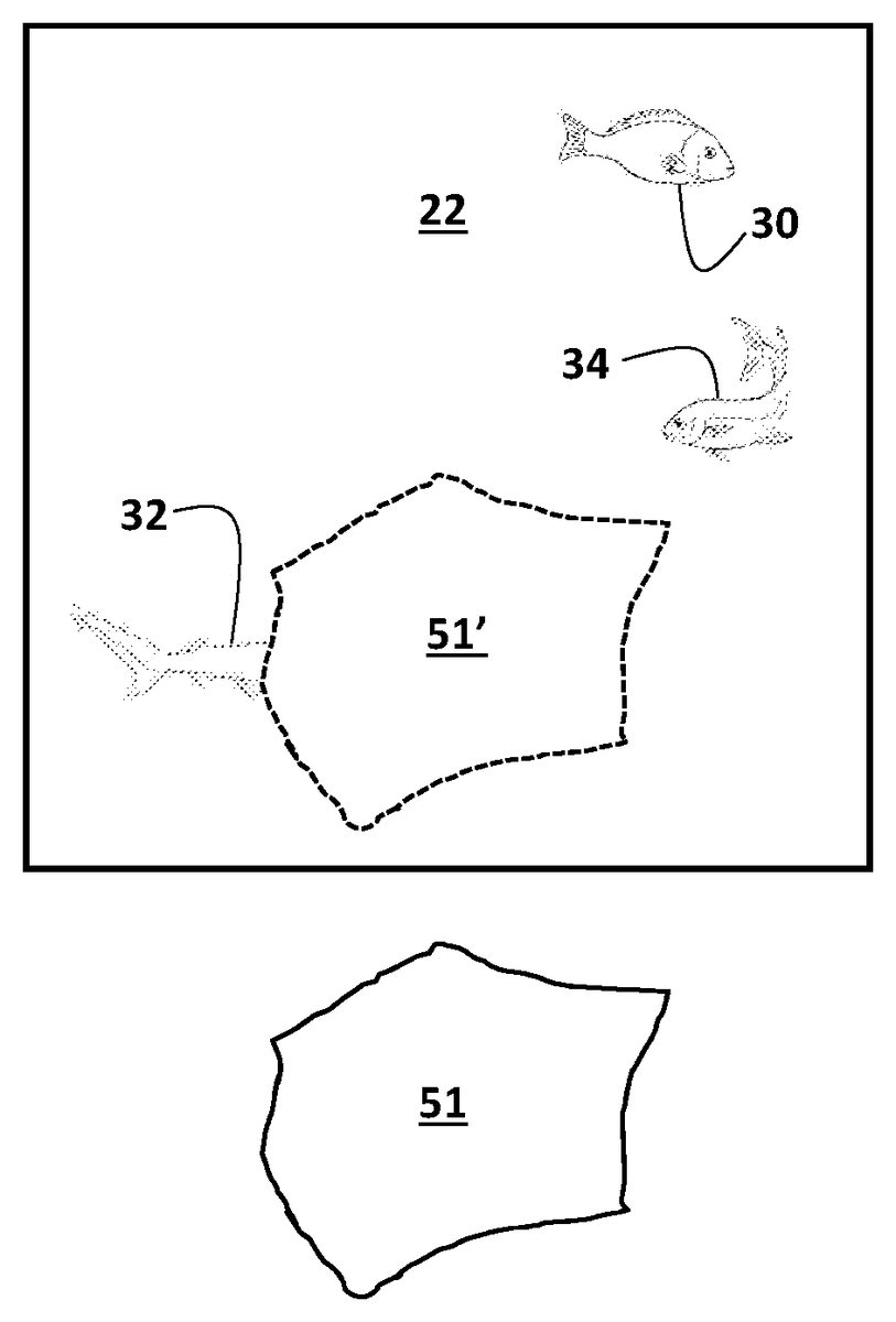
FIGS. 4A and 4Billustrate how the images projected from projector22can be made to appear to interact with the real world objects that are placed behind the beam splitter20relative to user100and behind beam splitter20′ relative to user200(as shown inFIG. 3).FIGS. 4A and 4Bare bottom plan views looking upward, directly into the projector22. From this view, the beam splitter is invisible. All that is seen is the direct image projected from the projector, which is again shown as fish30,32, and34. Object51represents a real world object, such as the enclosure38, or any other real world object, that is placed behind the beam splitter20or21′ relative to user100and/or200, respectively. The decorative or functional nature of the object is not relevant. Typically, the object would be a decorative element consistent with the theme of the video game being played.
Because the real world object51is behind the beam splitter20(relative to the player), the images reflected off the beam splitter will always appear to the player to be in front of (i.e., closer to the player) than the real world object. This is because the real world object is behind the beam splitter relative to the player, thus always placing the image reflected off the beam splitter physically closer to the player. However, the images reflected from the beam splitter can be made to appear to behind real world object51by projecting an opaque mask51′ from the projector22. The shape of the mask51′ corresponds to that of the real world object51, and is projected from the screen in registration with real world object51. If the real world object51is in motion, the mask51′ moves across the projector22in registration with the real world object51. Because the mask51′ is in registration with the real world object51, its reflection from the beam splitter20it is not seen by the players. Additionally, the color of the mask51′ may correspond to the background color or pattern being projected from projector22. The color or pattern of the mask51′ may be fixed or animated or otherwise dynamic. Thus, the mask51′ is not perceptible to the players. The other projected images, which are viewable by the players, such as fish30,32, and34, can be programmed either to “go behind” the mask51′ (that is, to be hidden by the mask), or to “go in front of” the mask51′ (that is, so that the image hides the mask). In most animation and rendering programs, the relevant computer command is designated “send to back” or “send backward” and “bring to front” or “bring forward.”
Thus, as shown inFIG. 4A, the image32is “sent backward” of the mask51′. Because the mask51′ is in registration with the corresponding real world object51, it appears to the players100and200that the image/fish32swims behind the real world object51. That is, when the image32is “sent backward” to be behind the mask51′, the parts of the image32that are superimposed with the mask51′ are no longer projected, and thus appears to the players to disappear behind real world object51. In contrast, as shown inFIG. 4B, the image34has been “brought forward” to be in front of mask51′. In this situation, the image34appears to be in front of real world object51, while image32appears to be behind real world image51, from the players' perspectives. For the images30,32, and34, the command “send backward” or “bring forward” of the mask51′ may be programmed dynamically (randomly or otherwise) so that the images30,32, and34will sometimes appear to be behind the real world object51and sometimes in front of the real world object51.
The ability of the two players to see each other adds another layer of complexity to the game play, regardless of whether the game being played is adversarial (for example, a war game that pits player100against player200) or a cooperative (for example, a strategy in which players100and200are a team). In either instance, the two players are able to communicate with one another verbally and through facial and hand signals.
Numerical ranges as used herein include every number and subset of numbers contained within that range, whether specifically disclosed or not. Further, these numerical ranges are to be construed as providing support for a claim directed to any number or subset of numbers in that range. For example, a disclosure of from 1 to 10 should be construed as supporting a range of from 2 to 8, from 3 to 7, from 1 to 9, from 3.6 to 4.6, from 3.5 to 9.9, and so forth.
All references to singular characteristics or limitations shall include the corresponding plural characteristic or limitation, and vice-versa, unless otherwise specified or clearly implied to the contrary by the context in which the reference is made.
All combinations of method or process steps as used herein can be performed in any order, unless otherwise specified or clearly implied to the contrary by the context in which the referenced combination is made.
The game console disclosed herein can comprise, consist of, or consist essentially of the essential elements and limitations described herein, as well as any additional or optional ingredients, components, or limitations described herein or otherwise useful in the field of arcade game consoles.
Claims
- A game console comprising: a housing having an open or transparent top and an open or transparent front;a projector situated on the top of the housing;a computer operationally connected to the projector and programmed to execute a video game;at least one controller operationally connected to the computer and dimensioned and configured to control play of the video game;a first beam splitter disposed inside the housing and positioned so that images generated by the projector are at least partially reflected from the first beam splitter and exit the front of the housing;a real world object disposed inside the housing at a position such that the beam splitter is situated between the real world object and the front face of the housing, and wherein at least a portion of light reflecting off of or projected from the real world object is transmitted through the first beam splitter and exits the front of the housing;wherein the projector generates an opaque mask whose shape corresponds to that of the real world object and is projected from the projector in registration with real world object and whose reflection from the beam splitter is not seen by players of the game;and wherein at least one other image projected by the projector and reflected off the beam splitter is no longer projected when it is superimposed with the opaque mask.
- The game console of claim 1 , wherein the housing further comprises a back having visible images disposed thereon.
- The game console of claim 1 , wherein the housing further comprises a back, and the back is a second projector operationally connected to the computer.
- The game console of claim 3 , wherein the first beam splitter is a plate of beam-splitting glass having a transmittance/reflectance (T/R) ratio of from about 20/80 to about 80/
- The game console of claim 3 , wherein the first beam splitter is a plate of beam-splitting glass having a transmittance/reflectance (T/R) ratio of from about 60/40 to about 50/
- The game console of claim 1 , wherein the first beam splitter is a plate of beam-splitting glass having a transmittance/reflectance (T/R) ratio of from about 20/80 to about 80/
- The game console of claim 1 , wherein the first beam splitter is a plate of beam-splitting glass having a transmittance/reflectance (T/R) ratio of from about 60/40 to about 50/
- The game console of claim 1 , wherein the housing further comprises an open or transparent back;and further comprising a second beam splitter disposed inside the housing and positioned so that images generated by the projector are at least partially reflected from the second beam splitter and exit the back of the housing;a real world object disposed inside the housing between the first beam splitter and the second beam splitter, and wherein at least a portion of light reflecting off of or projected from the real world object is transmitted through the first beam splitter and exits the front of the housing, and at least a portion of light reflecting off of or projected from the real world object is transmitted through the second beam splitter and exits the back of the housing.
- The game console of claim 8 , wherein the first and second beam splitters are plates of beam-splitting glass having a transmittance/reflectance (T/R) ratio of from about 20/80 to about 80/
- The game console of claim 8 , wherein the first and second beam splitters are plates of beam-splitting glass having a transmittance/reflectance (T/R) ratio of from about 60/40 to about 50/
- A game console comprising: a housing having an open or transparent top, an open or transparent front, and an open or transparent back;first and second projectors situated on the top of the housing;a computer operationally connected to the first and second projectors and programmed to execute a video game;at least two controllers operationally connected to the computer and dimensioned and configured to control play of the video game;a first beam splitter disposed inside the housing and positioned so that images generated by the first projector are at least partially reflected from the first beam splitter and exit the front of the housing;a second beam splitter disposed inside the housing and positioned so that images generated by the second projector are at least partially reflected from the second beam splitter and exit the back of the housing;a real world object disposed inside the housing between the first beam splitter and the second beam splitter, and wherein at least a portion of light reflecting off of or projected from the real world object is transmitted through the first beam splitter and exits the front of the housing, and at least a portion of light reflecting off of or projected from the real world object is transmitted through the second beam splitter and exits the back of the housing;wherein the projector generates an opaque mask whose shape corresponds to that of the real world object and is projected from the projector in registration with real world object and whose reflection from the beam splitter is not seen by players of the game;and wherein at least one other image projected by the projector and reflected off the beam splitter is no longer projected when it is superimposed with the opaque mask.
- The game console of claim 11 , wherein the first and second beam splitters are plates of beam-splitting glass having a transmittance/reflectance (T/R) ratio of from about 20/80 to about 80/
- The game console of claim 11 , wherein the first and second beam splitters are plates of beam-splitting glass having a transmittance/reflectance (T/R) ratio of from about 60/40 to about 50/50.
Disclaimer: Data collected from the USPTO and may be malformed, incomplete, and/or otherwise inaccurate.