U.S. Pat. No. 10,427,035
GAME CONTROLLER WITH REMOVABLE TRIGGER ACCESSORY
AssigneeMICROSOFT TECHNOLOGY LICENSING, LLC
Issue DateMarch 23, 2016
Illustrative Figure
Abstract
A game controller includes a trigger-activation sensor, a sensor-activation feature, and a trigger-retention feature. The sensor-activation feature is moveable relative to the trigger-activation sensor. The trigger-activation sensor outputs a control signal based on a relative position of the sensor-activation feature and the trigger-activation sensor. The trigger-retention feature is configured to removably affix a selected removable trigger accessory to the game controller. The selected removable trigger accessory is one of a plurality of differently configured removable trigger accessories removably affixable to the game controller. The selected removable trigger accessory is configured to change the relative position of the sensor-activation feature and the trigger-activation sensor based on finger manipulation of the selected removable trigger accessory when the selected removable trigger accessory is removably affixed to the game controller.
Description
DETAILED DESCRIPTION User input control devices, such as game controllers, may be shaped/sized to fit an average hand size of a population of users. Likewise, finger-manipulatable controls (e.g., push buttons, triggers, joysticks, directional pads) that are integral to a game controller have traditionally been designed according to a “one size fits all” approach. However, different users may have different preferences on the shape, size, color, texture, or other attributes of such controls. The present disclosure is directed to a customizable game controller that includes one or more differently configured trigger-type controls that can be swapped out in a tool-free manner. A trigger-type control may be any suitable control that is movable in a particular direction to generate a control signal based on a relative position of the trigger-type control in that direction. For example, differently configured removable trigger accessories may have different sizes, materials, ranges of motion, spring tensions, pull weights, and/or finger positions. In one example, such a configuration facilitates the use of differently configured removable trigger accessories that are customized for particular types of video games to be quickly swapped on the game controller when switching between playing different video games. In another example, such a configuration may facilitate the use of differently configured removable trigger accessories that are preferred by different players to be quickly swapped on the game controller when the game controller is used by the different players. FIGS. 1 and 2show an example user input control device in the form of a game controller100. The game controller100may be configured to translate user input into control signals that are provided to a computing device, such as a gaming console. The control signals may be mapped to commands to control a video game or perform other operations. For example, the game controller100may be configured to send ...
DETAILED DESCRIPTION
User input control devices, such as game controllers, may be shaped/sized to fit an average hand size of a population of users. Likewise, finger-manipulatable controls (e.g., push buttons, triggers, joysticks, directional pads) that are integral to a game controller have traditionally been designed according to a “one size fits all” approach. However, different users may have different preferences on the shape, size, color, texture, or other attributes of such controls.
The present disclosure is directed to a customizable game controller that includes one or more differently configured trigger-type controls that can be swapped out in a tool-free manner. A trigger-type control may be any suitable control that is movable in a particular direction to generate a control signal based on a relative position of the trigger-type control in that direction. For example, differently configured removable trigger accessories may have different sizes, materials, ranges of motion, spring tensions, pull weights, and/or finger positions. In one example, such a configuration facilitates the use of differently configured removable trigger accessories that are customized for particular types of video games to be quickly swapped on the game controller when switching between playing different video games. In another example, such a configuration may facilitate the use of differently configured removable trigger accessories that are preferred by different players to be quickly swapped on the game controller when the game controller is used by the different players.
FIGS. 1 and 2show an example user input control device in the form of a game controller100. The game controller100may be configured to translate user input into control signals that are provided to a computing device, such as a gaming console. The control signals may be mapped to commands to control a video game or perform other operations. For example, the game controller100may be configured to send control signals via a wired or wireless connection with a computing device.
The game controller100includes a grip102configured to be held with two hands. As such, the grip102includes a left-hand portion104configured to be gripped by a left hand and a right-hand portion106configured to be gripped by a right hand. The right-hand portion106may oppose the left-hand portion104. When a user holds the controller100with two hands such that the left hand grips the left-hand portion104and the right hand grips the right-hand portion106, the user's thumbs may naturally interface with a thumb-side108of the grip102. Further, the user's fingers other than the thumb (e.g., at least a ring finger and a pinky finger) may interface with a finger-side110of the grip102.
The game controller100includes a plurality of controls112configured to generate different control signals responsive to finger manipulation. In the depicted implementation, the plurality of controls112includes a plurality of action buttons114(e.g.,114A,114B,114C,114D,114E,114F,114G, and114H), a plurality of joysticks116(e.g., a left joystick116A and a right joystick116B), a directional pad118, and a plurality of triggers120(e.g., a left trigger120A and a right trigger120B). A majority of the controls112are positioned on the thumb-side108of the game controller100As such, the plurality of controls112typically may be manipulated by a user's thumbs. The plurality of triggers120are positioned on a side122intermediate the thumb-side108and the finger-side110and oriented non-parallel to the thumb-side108and the finger-side110to allow the triggers120to be manipulated by index fingers and/or middle fingers when a user grips the game controller100with two hands. In some cases, a user may manipulate one or more of the plurality of controls112according to another hand configuration. The game controller100may include any suitable number of controls. The game controller100may include any suitable type of controls.
In the illustrated implementation, the game controller100includes a printed circuit board124located in an interior of the grip102. The printed circuit board124may include a plurality of control-activation sensors126. The plurality of control-activation sensors126may correspond to the plurality of controls112. In particular, each control-activation sensor may be configured to generate a control signal responsive to interaction with a corresponding control.
In one example, each of the plurality of action buttons114may be configured to activate a corresponding button-activation sensor to generate a control signal responsive to being depressed (e.g., via finger manipulation). In another example, each of the plurality of joysticks116may interact with joystick-activation sensors in the form of potentiometers that use continuous electrical activity to provide an analog input control signal based on a position of the joystick in relation to a default “center” position. In another example, the directional pad118may be configured to activate different directional pad-activation sensors corresponding to different directions (e.g., up, down, left, right) responsive to the directional pad being depressed in the different directions. In another example, each of the triggers120may be configured to interact with a trigger-activation sensor to provide a variable control signal based on a position of the trigger relative to a default position. For example, as a trigger is pulled farther away from the default position, a characteristic of the generated control signal may increase in magnitude.
Non-limiting examples of control-activation sensors may include dome switches, tactile switches, potentiometers, Hall Effect sensors, and other electronic sensing components. The game controller100may include any suitable number of control-activation sensors. The game controller100may include any suitable type of control-activation sensors. In some implementations, one or more control-activation sensors may be independent of any printed circuit board.
Each of the triggers120may be one of a plurality of differently configured removable trigger accessories removably affixable to the game controller100. For example, various differently configured removable trigger accessories may have different sizes, shapes, textured surfaces, materials, and/or other features that are preferred by different users or may be suited for particular gaming or other purposes.
In some implementations, one or more of the plurality of controls112other than the triggers120also may be removably affixable to the game controller100.
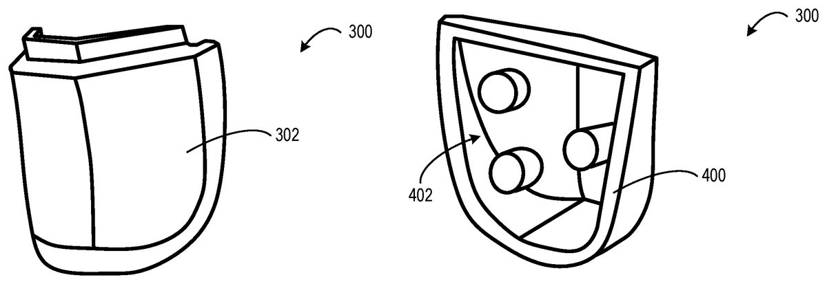
FIGS. 3-5show a removable trigger accessory300configured to magnetically affix to a game controller500.FIG. 3shows an exterior side302of the removable trigger accessory300. The exterior side302may be contoured to fit a user's finger. In the depicted example, the exterior side302forms a ramp that extends downward and outward towards a bottom end of the removable trigger accessory300. The ramp may aid a user in precisely adjusting a position of the removable trigger accessory300when the removable trigger accessory300is removably affixed to the game controller500. The exterior side302may include any suitable surface, feature, shape, material, texture, and/or structure configured to be touched and/or manually manipulated by a finger to provide user input.
FIG. 4shows an interior side400of the removable trigger accessory300. The interior side400includes a mounting interface402configured to interface with a trigger-retention feature502(shown inFIG. 5) of the game controller500to removably affix the removable trigger accessory300to the game controller500. In the depicted example, the mounting interface402includes three magnetic posts arranged to form a mounting interface with the trigger-retention feature502.
FIG. 5shows the trigger-retention feature502depicted in the form of three magnetic posts formed on a mounting platform504of the game controller500. In particular, the mounting platform504and three magnetic posts of the trigger-retention feature502may be recessed within a grip506of the game controller500. The three magnetic posts of the trigger-retention feature502may be arranged to align with the three magnetic posts of the mounting interface402.
The mounting interface402may include any suitable surface, feature, shape, and/or structure configured to selectively mate with the trigger-retention feature502to removably affix the removable trigger accessory300to the game controller500. In some implementations, the mounting interface402of the removable trigger accessory300may have a shape that complements a shape of the trigger-retention feature502. Such corresponding interfaces may aid the removable trigger accessory300in aligning with the trigger-retention feature502to removably affix the removable trigger accessory300to the game controller500.
The removable trigger accessory300may be configured to removably affix to the game controller500through a magnetic attraction. For example, the three posts of the trigger-retention feature502may be magnets and the three corresponding posts of the mounting interface402may be made of ferromagnetic material. Accordingly, the removable trigger accessory300may be removably affixable to the game controller500through a magnetic attraction between the magnets of the trigger-retention feature and the ferromagnetic material of the mounting interface.
In some implementations, the removable trigger accessory300may be a single ferromagnetic metal part. For example, the metal part may be metal injection-molded. In another example, the part may be machined from a single piece of metal. In other implementations, the removable trigger accessory300may be an assembly including one or more ferromagnetic parts. For example, the three posts of the mounting interface402may be ferromagnetic material that is bonded to a plastic faceplate.
In some implementations, the three posts of the trigger-retention feature502may be made of ferromagnetic material and the three corresponding posts of the mounting interface402may be magnets. Accordingly, the removable trigger accessory300may be removably affixable to the game controller500through a magnetic attraction between the magnets of the mounting interface and the ferromagnetic material of the trigger retention feature.
The mounting interface402and/or the trigger-retention feature502may include any suitable number of cooperating magnets and/or pieces of ferromagnetic material. Further, such magnets and/or pieces of ferromagnetic material may take any suitable form.
When the removable trigger accessory300is removably affixed to the game controller500, the removably trigger accessory300may appear as if integrated or permanently installed in the game controller500. The removable trigger accessory300may be configured to reside in a default posture when no touch force is applied to the removable trigger accessory300. Further, the removable trigger accessory300may be configured to move from the default posture based on finger manipulation.
When the removable trigger accessory300is removably affixed to the game controller500, the removable trigger accessory300may be configured to change a position of the mounting platform504based on finger manipulation of the removable trigger accessory300. In particular, the mounting platform504may move further into an interior of the grip506when the removable trigger accessory300is depressed. A sensor-activation feature508may be positioned on an opposing side of the mounting platform504relative to the three posts of the trigger-retention feature502. When the mounting platform504moves into the interior of the grip102, a relative position of the sensor-activation feature508and a trigger-activation sensor510may change. The trigger-activation sensor510may output a control signal that is based on the relative position of the sensor-activation feature508and the trigger-activation sensor510. In one example, the sensor-activation feature508includes a magnet and the trigger-activation sensor510is a Hall Effect sensor configured to vary an output signal based on the magnetic field produced by the magnet. The magnetic field as detected by the Hall Effect sensor may vary based on the relative position and/or orientation of the magnet and the Hall Effect sensor. The control signal produced by the trigger-activation sensor510may be any signal that differs from a signal or lack thereof produced by the trigger-activation sensor510when the removable trigger accessory300is in the default posture.
The removable trigger accessory300is one of a plurality of differently configured removable trigger accessories that may be removably affixable to the trigger-retention feature502of the game controller500through a magnetic attraction between the mounting interface402and the trigger-retention feature502.
FIGS. 6-7show a removable trigger accessory600configured to electrically connect with a trigger-retention feature702of the game controller700.FIG. 6shows the interior side602of the removable trigger accessory600that contains an electronic module604. The electronic module604includes a mounting interface configured to interface with a trigger-retention feature702(shown inFIG. 7) of the game controller700to removably affix the removable trigger accessory600to the game controller700. In the depicted example, the mounting interface includes three male electrical contacts606that protrude from the electronic module604.
FIG. 7shows a trigger-retention feature of the game controller700depicted in the form of an outlet702. The outlet702may be recessed within a grip704of the game controller700. The outlet702includes three female electrical contacts706arranged to align with the three male electrical contacts606of the electronic module604of the removable trigger accessory600. The interface between the male electrical contacts606of the electronic module604and the female electrical contacts706of the outlet702may provide an electrical and mechanical connection between the removable trigger accessory600and the game controller700. The electronic module604may electrically and/or mechanically connect with the outlet702in any suitable manner. In some implementations, the trigger-retention feature and/or the removable trigger accessory may include additional magnetic and/or mechanical interfaces to removably affix the removable trigger accessory600to the game controller700.
The electronic module604may be configured to perform any suitable operation that uses energy provided by the game controller700or that provides energy to the game controller700through the electrical connection between the electronic module604and the outlet702. The electronic module604may include any suitable electronic componentry including, but not limited to, a linear force reactor, a haptic feedback motor, LEDs or other lights, a speaker, a buzzer, a shock device, a heater, a Peltier cooler, a balanced motor for a gyroscope, and a battery.
In some implementations, the electronic module604may be permanently attached to the removable trigger accessory600. In some such implementations, differently configured removable trigger accessories may include differently configured electronic modules. For example, a removable trigger accessory including a haptic feedback motor may be swapped on the game controller for a different removable accessory having flashing LEDs. In other implementations, the electronic module604may be removable from the removable trigger accessory600. In some such implementations, differently configured electronic modules may be swapped out of the same removable trigger accessory600that is removably affixable to the game controller700.
In some implementations, in addition to the outlet702, the game controller700may include mechanical and/or magnetic trigger-retention features configured to removably affix the removable trigger accessory600to the game controller700. Likewise, the removable trigger accessory600may include cooperating mechanical and/or magnetic mounting interfaces configured to removably affix the removable trigger accessory600to the game controller700.
FIGS. 8-13show a removable trigger accessory800configured to removably affix to a game controller802through a mechanical connection. The game controller802includes a plurality of mechanical trigger-retention features in the form of a mating slot804(shown inFIG. 11) and a male buckle portion806(shown inFIG. 9). Further, the removable trigger accessory800includes a hook808(shown inFIG. 11) and a female buckle portion810(shown inFIG. 9). The hook808may be configured to engage the mating slot804and the female buckle portion810may be configured to engage the male buckle portion806to removably affix the removable trigger accessory800to the game controller802.
FIG. 9shows the female buckle portion810of the removable trigger accessory800being pressed on to the male buckle portion806to removably affix the removable trigger accessory800to the game controller802. The female buckle portion810may include two compliant spurs900(900A,900B) that bend around a head902of the male buckle portion806when the removable trigger accessory800is pressed on to the male buckle portion806. Each spur900may include an angled interior surface that interfaces with the head902to aid the spur900in sliding around the head902. In some implementations, additionally or alternatively, the spurs900may be hinged and may rotate to move around the head902of the male buckle portion806.
FIG. 10shows the female buckle portion810of the removable trigger accessory800fully installed on to the male buckle portion806. In particular, the spurs900of the female buckle portion810have cleared the head902of the male buckle portion806, so that the head902mechanically retains the spurs900to removably affix the removable trigger accessory800to the game controller802. Further, a back side of the head902may include angled surfaces that interface with the spurs900to aid the spurs900in sliding back around the head902when the removable trigger accessory800is removed from the game controller802. In other words, the male buckle portion806may act like a barbless hook that allows the female buckle portion810to slip on and off.
FIG. 11shows the removable trigger accessory800oriented to be installed on the game controller802. In particular, the removable trigger accessory800may be rotated to allow the hook808to be inserted into an interior of the game controller802far enough to clear the mating slot804. As shown inFIG. 12, once the hook808has cleared the mating slot804, the removable trigger accessory800may be rotated so that the hook808engages the mating slot804to mechanically affix the removable trigger accessory800to the game controller802. Furthermore, when the removable trigger accessory800is rotated, the female buckle portion810may mechanically engage the male buckle portion806.
FIG. 13shows the removable trigger accessory800being manipulated by a touch force1300when the removable trigger accessory800is removably affixed to the game controller802. In particular, the hook808and the mating slot804collectively form a pivot, and the removable trigger accessory800is configured to rotate about the pivot based on the touch force1300. An amount of rotation of the removable trigger accessory800may correspond to a magnitude of the touch force1300applied to the removable trigger accessory800.
Furthermore, the game controller802includes a sensor-activation feature1302that is positioned on an interior side of the male buckle portion806. The sensor-activation feature1302may be moveable relative to a trigger-activation sensor1304. In particular, when the removable trigger accessory800rotates based on the touch force1300, the removable trigger accessory800changes the relative position of the sensor-activation feature1302and trigger-activation sensor1304(e.g., the sensor-activation feature1302moves closer to the trigger-activation sensor1304). The trigger-activation sensor1304may output a control signal based on a relative position of the sensor-activation feature1302and the trigger-activation sensor1304. In other implementations, the sensor-activation feature1302may be attached to the removable trigger accessory800.
The removable trigger accessory800may be mechanically affixed to the game controller802via any suitable number and/or type of mechanical trigger-retention feature(s). For example, such mechanical trigger-retention features may include, but are not limited to, posts, holds, sockets, snaps, latches, pins, and buttons.
In configurations where a removable trigger accessory rotates based on finger manipulation, there is a possibility that the removable trigger accessory may become unintentionally detached from the game controller. However, in the configuration described above, by employing two separate mechanical trigger-retention features that are spaced apart from one another, the removable trigger accessory may be less likely to become unintentionally detached from the game controller relative to a configuration having a single mechanical attachment.
FIGS. 14-16show a removable trigger accessory1400configured to removably affix to a game controller1402through a mechanical connection as well as a magnetic connection. The game controller1402includes a mounting platform1404including a mechanical trigger-retention feature in the form of a mating slot1406and magnetic trigger-retention feature in the form of a magnet1408. The mating slot1406may be centrally located on the mounting platform1404. The magnet1408is positioned on a lower portion of the mounting platform1404. The magnet1408may be attached to the mounting platform1404in any suitable manner. For example, the magnet1408may be attached to the mounting platform1404via an adhesive. In some implementations, the magnet1408may be alternatively positioned on an upper portion of the mounting platform1404above the mating slot1406. In some implementations, a second magnet may be positioned on the upper portion of the mounting platform1404above the mating slot1406.
The removable trigger accessory1400includes a hook1410and a piece of ferromagnetic material1412. The hook1410may be configured to engage the mating slot1406and the piece of ferromagnetic material1412may be configured to be magnetically attracted to the magnet1408to removably affix the removable trigger accessory1400to the game controller1402.
The mounting platform1404includes a pivot1414that allows the mounting platform1404to rotate the removable trigger accessory1400when the removable trigger accessory1400is removably affixed to the game controller1402.
FIG. 14shows the removable trigger accessory1400oriented to be installed on the game controller1402. In particular, the removable trigger accessory1400may be rotated to allow the hook1410to be inserted through the mating slot1406. As shown inFIG. 13, once the hook1410has been inserted into the mating slot1406, the removable trigger accessory1400may be rotated so that the piece of ferromagnetic material1412aligns with the magnet1408to mechanically and magnetically affix the removable trigger accessory1400to the game controller1402.
FIG. 15shows the removable trigger accessory1400being manipulated by a touch force1500when the removable trigger accessory1400is removably affixed to the game controller1402. In particular, the mounting platform1404rotates about the pivot1414to change a position of the removable trigger accessory1400. An amount of rotation of the pivot1414may correspond to a magnitude of the touch force1500applied to the removable trigger accessory1400.
Furthermore, the game controller1402includes a sensor-activation feature1502that may be moveable relative to a trigger-activation sensor1504. The removable trigger accessory1400includes a range of motion adjuster1506configured to adjust a range of motion of the sensor-activation feature1502. As depicted, the range of motion adjuster1506is a pin that extends from a base of the removable trigger accessory1400into the interior of the game controller1402when the removable trigger accessory1400is removably affixed to the mounting platform1404. The length of the pin may define a range of motion that the sensor-activation feature1502can travel. In particular, when the removable trigger accessory1400rotates based on the touch force1500, the range of motion adjuster1506pushes the sensor-activation feature1502closer to the trigger-activation sensor1504. When the removable trigger accessory1400has been fully rotated, the distance traveled by the sensor-activation feature1502may be the full range of motion as defined by the range of motion adjuster1506. In other implementations, the sensor activation feature1502may be attached to the trigger accessory1400or the mounting platform1404and the motion adjuster1506may interface with another surface or component within the game controller1402.
FIG. 16shows a removable trigger accessory1600including a range of motion adjuster1602having a shorter pin relative to the range of motion adjuster1506of the removable trigger accessory1400. Accordingly, when the removable trigger accessory1600is removably affixed to the game controller1402and when the same touch force1500is applied to the removable trigger accessory1600to fully rotate the removable trigger accessory1600, the range of motion adjuster1602moves the sensor-activation feature1502a shorter travel distance relative to a travel distance of the sensor-activation feature1502as moved by the range of motion adjuster1506. In other words, the range of motion adjuster1602may be configured to shorten a range of motion of the sensor-activation feature relative to the range of motion adjuster1506of the removable trigger accessory1400.
A removable trigger accessory may include a range of motion adjuster configured to adjust a range of motion to any suitable range. Moreover, differently configured removable trigger accessories may include different range of motion adjusters configured to differently adjust a range of motion of a sensor-activation feature. Accordingly, different removable trigger accessories may be swapped on a game controller to change a range of motion of the trigger. For example, a removable trigger accessory having a range of motion adjuster that reduces a range of motion may be removably affixed to a game controller to play a first-person-shooter game, because the short range of motion may create a “hair trigger.” On the other hand, a removable trigger accessory having a range of motion adjust that increases a range of motion may be removably affixed to the game controller to play a racing game where the trigger is used as a brake pedal in order to have precise braking of a race car.
FIGS. 17-19show a removable trigger accessory1700configured to removably affix to spring-loaded mounting platform1702of a game controller1704through a magnetic connection. The spring-loaded mounting platform1702may be biased by a torsion spring1706to maintain the mounting platform1702in a default posture. The mounting platform1702includes a slot1708and a pair of magnets1710. The slot1708may be centrally located on the mounting platform1702. The pair of magnets1710may be positioned above and below the slot1708, respectively. The mounting platform1702includes a pivot1712that allows the mounting platform1702to rotate the removable trigger accessory1700when the removable trigger accessory1700is removably affixed to the game controller1704.
The removable trigger accessory1700includes a spring tensioner1714and a pair of ferromagnetic pieces1716. The spring tensioner1714may be configured to pass through the slot1708and interface with a receiver plate1718of the torsion spring1706to adjust an amount of spring force applied by the torsion spring1706to the mounting platform1702. In particular, a length of the spring tensioner1714may define an amount of spring force applied by the torsion spring1706to the mounting platform1702. The pair of ferromagnetic pieces1716may be configured to be magnetically attracted to the pair of magnets1710to removably affix the removable trigger accessory1700to the game controller1704.
FIG. 18shows the removable trigger accessory1700being manipulated by a touch force1800when the removable trigger accessory1700is removably affixed to the game controller1704. In particular, the touch force1800is great enough to overcome the bias of the torsion spring1706to rotate the mounting platform1702about the pivot1712to change a position of the removable trigger accessory1700. An amount of rotation of the pivot1712may correspond to a magnitude of the touch force1800relative to the spring force applied by the torsion spring1706. When the touch force1800is no longer applied to the removable trigger accessory1700, the torsion spring1706returns the mounting platform1702to the default posture.
FIG. 19shows a removable trigger accessory1900including a spring tensioner1902having a longer pin relative to the spring tensioner1714of the removable trigger accessory1700. In particular, the longer pin of the spring tensioner1902may apply a greater force to the receiver plate1718of the torsion spring1706of the game controller1704relative to the spring tensioner1714of the removable trigger accessory1700. Accordingly, when the same touch force1800is applied to the removable trigger accessory1900, the removable trigger accessory1900may travel a shorter distance relative to a travel distance of the removable trigger accessory1700. In other words, a greater touch force may be required to cause the removable trigger accessory1900to travel a same distance as the removable trigger accessory1700.
A removable trigger accessory may include a spring tensioner configured to adjust an amount of spring force applied by a spring to any suitable spring force. Moreover, differently configured removable trigger accessories may include different spring tensioners configured to differently adjust an amount of spring force applied by a spring. Accordingly, different removable trigger accessories may be swapped on a game controller to change a spring tension of a trigger. For example, a removable trigger accessory having a lesser spring tension may be removably affixed to a game controller to play a first-person-shooter game, because the less spring tension may allow for more rapid fire shooting. On the other hand, a removable trigger accessory having a greater spring tension may be removably affixed to the game controller to play a racing game where the trigger is used as a brake pedal in order to have precise braking of a race car.
FIGS. 20-22show a removable trigger accessory2000configured to removably affix to a spring-loaded mounting platform2002of a game controller2004through a magnetic connection. The spring-loaded mounting platform2002may be biased by a coil spring2006to maintain the mounting platform2002in a default posture. The mounting platform2002includes a slot2008and a pair of magnets2010. The slot2008may be centrally located on the mounting platform2002. The pair of magnets2010may be positioned above and below the slot2008, respectively. The mounting platform2002includes a pivot2012that allows the mounting platform2002to rotate the removable trigger accessory2000when the removable trigger accessory2000is removably affixed to the game controller2004.
The removable trigger accessory2000includes an adjustable spring tensioner2014and a pair of ferromagnetic pieces2016. The adjustable spring tensioner2014may be configured to pass through the slot2008and interface with the coil spring2006to adjust an amount of spring force applied by the coil spring2006to the mounting platform2002via the adjustable spring tensioner2014. In particular, a length of the adjustable spring tensioner2014may define an amount of spring force applied by the coil spring2006to the mounting platform2002. In the depicted example, the adjustable spring tensioner2014is a set screw that is rotatable to adjust a length of a portion that passes through the slot2008and interfaces with the coil spring2006. The pair of ferromagnetic pieces2016may be configured to be magnetically attracted to the pair of magnets2010to removably affix the removable trigger accessory2000to the game controller2004.
FIG. 21shows the removable trigger accessory2000being manipulated by a touch force2100when the removable trigger accessory2000is removably affixed to the game controller2004. In particular, the touch force2100is great enough to overcome the bias of the coil spring2006to rotate the mounting platform2002about the pivot2012to change a position of the removable trigger accessory2000. An amount of rotation of the pivot2012may correspond to a magnitude of the touch force2100relative to the spring force applied by the coil spring2006to the adjustable spring tensioner2014. When the touch force2100is no longer applied to the removable trigger accessory2000, the coil spring2006returns the mounting platform2002to the default posture.
FIG. 22shows the removable trigger accessory2000with the adjustable spring tensioner2014adjusted to have a longer portion protrude through the slot2008relative to a length of the portion shown inFIG. 21. For example, the adjustable spring tensioner2104may be screwed in further to increase the length of the protruding portion. In particular, the longer portion of the adjustable spring tensioner2014applies a greater force to the coil spring2006relative to the amount of force applied by the adjustable spring tensioner2014as shown inFIG. 21. Accordingly, when the same touch force2100is applied to the removable trigger accessory2000, the removable trigger accessory2000may travel a shorter distance relative to a travel distance of the removable trigger accessory2000when the set screw is screwed in to a lesser degree as shown inFIG. 21. In other words, a greater touch force may be required to cause the removable trigger accessory2000configured as shown inFIG. 22to travel a same distance as the removable trigger accessory2000configured as shown inFIG. 21.
A removable trigger accessory may include an adjustable spring tensioner configured to adjust an amount of spring force applied by a spring to any suitable spring force. Moreover, an adjustable spring tensioner may adjust and amount of spring force applied by any suitable type of spring in any suitably manner.
FIGS. 23-25show a plurality of differently configured removable trigger accessories having differently configured finger interfaces that enable different types of finger manipulation.
FIG. 23shows a removable trigger accessory2300including a finger interface2302configured to accommodate two fingers in an over-under configuration. The removable trigger accessory2300is removable affixed to a game controller2304. The finger interface2302is elongated to extend beyond a bottom or finger-side2306of the game controller2304when the removable trigger accessory2300is removably affixed to the game controller2304. For example, the two finger over-under configuration of the finger interface2302may allow a user to manipulate the removable trigger accessory2300using an index finger and a middle finger. The two finger configuration may provide additional contact area relative to a single finger configuration that may be preferred by some users. In another example, the two finger over-under configuration of the finger interface2302may allow a user to manipulate the removable trigger accessory2300using a middle finger and a ring finger. Such a configuration may allow for the user to user an index finger to control a bumper button positioned above the trigger on the game controller.
FIG. 24shows a removable trigger accessory2400including a finger interface2402configured to bend below a bottom or finger-side2404of a game controller2406when the removable trigger accessory2400is removably affixed to the game controller2406. For example, the bent configuration of the finger interface2402may change a finger manipulation angle of the trigger that allows a user to manipulate the removable trigger accessory2400from the finger-side2404of the game controller2406instead of a side that is perpendicular to the finger-side2404. For example, the bent configuration of the finger interface2402may allow a user to manipulate the removable trigger accessory2400using a different finger, such as a ring finger. In another example, the bent configuration of the finger interface2402may allow a user to manipulate the removable trigger accessory2400using a non-traditional type of grip of the game controller2406.
FIG. 25shows a removable trigger accessory2500including an extra-large finger interface2502configured to extend both laterally along a front side of2504and longitudinally below a finger-side2506of a game controller2508when the removable trigger accessory2500is removably affixed to the game controller2508. For example, the extra-large configuration of the finger interface2502may provide additional surface area to accommodate different grip styles (e.g., multiple fingers) or larger fingers relative to a traditional-sized finger interface sized to accommodate a single finger.
Different removable trigger accessories may be configured differently to provide different gameplay experiences. For example, different trigger accessories may include finger interfaces having different dimensions including different lengths, widths, and curvatures. In some implementations, a finger interface may include one or more bends and/or one or more twists relative to the portion of the removable trigger accessory on which a mounting interface is located. For example, a finger interface may bend upwards towards the thumb-side or downwards towards the finger-side. In another example, a finger interface may be twisted inwards towards the center of the game controller or outwards towards edges of the game controller. In another example, a finger interface may include a combination of one or more bends and one or more twists.
As another example, different removable trigger accessories may have finger interfaces having different cross-sectional shapes including circular or elliptical shapes, angular shapes including shapes having squared-off corners, and other suitable shapes. As another example, different removable trigger accessories may have finger interfaces having different degrees of convexity or concavity. As another example, different removable trigger accessories may have different textures including smooth textures, rough textures, or other suitable textures. Some textures may be formed from different material coatings applied to the finger interface. Other textures may be formed by a structure of the finger interface itself. A removable trigger accessory may include a finger interface sized, shaped, and/or textured in any suitable manner.
Additional aspects of the present disclosure are described below. According to one aspect, a game controller comprises a trigger-activation sensor, a sensor-activation feature moveable relative to the trigger-activation sensor, wherein the trigger-activation sensor outputs a control signal based on a relative position of the sensor-activation feature and the trigger-activation sensor, and a trigger-retention feature configured to removably affix a selected removable trigger accessory to the game controller, the selected removable trigger accessory being one of a plurality of differently configured removable trigger accessories removably affixable to the game controller, the selected removable trigger accessory configured to change the relative position of the sensor-activation feature and the trigger-activation sensor based on finger manipulation of the selected removable trigger accessory when the selected removable trigger accessory is removably affixed to the game controller. In this aspect, the trigger-retention feature may include one or more magnets, the selected removable trigger accessory may be made at least partially of ferromagnetic material, and the selected removable trigger accessory may be removably affixable to the game controller through a magnetic attraction between the one or more magnets and the ferromagnetic material. In this aspect, the selected removable trigger accessory may include one or more magnets, the trigger-retention feature may made at least partially of ferromagnetic material, and the selected removable controller accessory may be removably affixable to the game controller through a magnetic attraction between the one or more magnets and the ferromagnetic material. In this aspect, the selected removable trigger accessory may include a hook, and the trigger-retention feature may include a mating slot configured to receive the hook to removably affix the selected removable trigger accessory to the game controller. In this aspect, the trigger-retention feature and the hook may collectively form a pivot, and the selected removable trigger accessory may be configured to rotate about the pivot based on finger manipulation of the selected removable trigger accessory when the selected removable trigger accessory is removably affixed to the game controller. In this aspect, at least one of the plurality of differently configured removable trigger accessories may include an electronic module, and the trigger-retention feature may include an outlet configured to connect with the electronic module. In this aspect, the game controller may further comprise a spring biased to maintain the selected removable trigger accessory in a default posture when the selected removable trigger accessory is removably affixed to the game controller, and the plurality of differently configured removable trigger accessories may each include a different spring tensioner configured to differently adjust an amount of spring force applied by the spring. In this aspect, the game controller may further comprise a spring biased to maintain the selected removable trigger accessory in a default posture when the selected removable trigger accessory is removably affixed to the game controller, and the selected removable trigger accessory may include an adjustable spring tensioner configured to adjust an amount of spring force applied by the spring. In this aspect, the plurality of differently configured removable trigger accessories each may include a different range of motion adjuster configured to differently adjust a range of motion of the sensor-activation feature relative to the trigger-activation sensor. In this aspect, the game controller may further comprise a grip including a thumb-side including one or more controls configured to be manipulated by a thumb, and the trigger-retention feature may be configured to position the selected removable trigger accessory to be manipulated by an index finger when the selected removable trigger accessory is removably affixed to the game controller. In this aspect, the selected removable trigger accessory may extend beyond a finger-side of the grip that opposes the thumb side when the selected removable trigger accessory is removably affixed to the game controller.
According to another aspect, a game controller comprises a trigger-activation sensor, a sensor-activation feature moveable relative to the trigger-activation sensor, wherein the trigger-activation sensor outputs a control signal based on a relative position of the sensor-activation feature and the trigger-activation sensor, a trigger-retention feature including one or more magnets and configured to magnetically affix to the game controller a selected removable trigger accessory made at least partially of ferromagnetic material, the selected removable trigger accessory being one of a plurality of differently configured removable trigger accessories magnetically affixable to the game controller, the selected removable trigger accessory configured to change the relative position of the sensor-activation feature and the trigger-activation sensor based on finger manipulation of the selected removable trigger accessory when the selected removable trigger accessory is magnetically affixed to the game controller. In this aspect, the selected removable trigger accessory may include a hook, and the trigger-retention feature may include a mating slot configured to receive the hook to magnetically affix the selected removable trigger accessory to the game controller. In this aspect, the mating slot and the hook may collectively form a pivot, and the selected removable trigger accessory may be configured to rotate about the pivot based on finger manipulation of the selected removable trigger accessory when the selected removable trigger accessory is affixed to the game controller. In this aspect, at least one of the plurality of differently configured removable trigger accessories may include an electronic module, and the trigger-retention feature may include an outlet configured to connect with the electronic module. In this aspect, the game controller may further comprise a spring biased to maintain the selected removable trigger accessory in a default posture when the selected removable trigger accessory is magnetically affixed to the game controller, and the plurality of differently configured removable trigger accessories each may include a different spring tensioner configured to differently adjust an amount of spring force applied by the spring. In this aspect, the game controller may further comprise a spring biased to maintain the selected removable trigger accessory in a default posture when the selected removable trigger accessory is magnetically affixed to the game controller, and the selected removable trigger accessory may include an adjustable spring tensioner configured to adjust an amount of spring force applied by the spring. In this aspect, the plurality of differently configured removable trigger accessories each may include a different range of motion adjuster configured to differently adjust the range of motion of the sensor-activation feature.
According to another aspect, a game controller, comprises a trigger-activation sensor, a sensor-activation feature moveable relative to the trigger-activation sensor, wherein the trigger-activation sensor outputs a control signal based on a relative position of the sensor-activation feature and the trigger-activation sensor, a trigger-retention feature including one or more magnets and a mechanical retention feature, the one or more magnets configured to magnetically affix to the game controller a selected removable trigger accessory made at least partially of ferromagnetic material, the mechanical retention feature configured to mechanically affix the selected removable trigger accessory to the game controller through mechanical engagement of the mechanical retention feature and the selected removable trigger accessory, the selected removable trigger accessory being one of a plurality of differently configured removable trigger accessories magnetically and mechanically affixable to the game controller, the selected removable trigger accessory configured to change the relative position of the sensor-activation feature and the trigger-activation sensor based on finger manipulation of the selected removable trigger accessory when the selected removable trigger accessory is magnetically and mechanically affixed to the game controller. In this aspect, the game controller may further comprise a grip including a thumb-side including one or more controls configured to be manipulated by a thumb, and the trigger-retention feature may be configured to position the selected removable trigger accessory to be manipulated by an index finger when the selected removable trigger accessory is magnetically and mechanically affixed to the game controller.
It will be understood that the configurations and/or approaches described herein are exemplary in nature, and that these specific embodiments or examples are not to be considered in a limiting sense, because numerous variations are possible. The specific routines or methods described herein may represent one or more of any number of processing strategies. As such, various acts illustrated and/or described may be performed in the sequence illustrated and/or described, in other sequences, in parallel, or omitted. Likewise, the order of the above-described processes may be changed.
The subject matter of the present disclosure includes all novel and nonobvious combinations and subcombinations of the various features disclosed herein, as well as any and all equivalents thereof.
Claims
- A game controller, comprising: a trigger-activation sensor;a sensor-activation feature moveable relative to the trigger-activation sensor, wherein the trigger-activation sensor outputs a control signal based on a relative position of the sensor-activation feature and the trigger-activation sensor;and a mounting platform including a trigger-retention feature configured to removably affix a selected removable trigger accessory to the mounting platform, the selected removable trigger accessory being one of a plurality of differently configured removable trigger accessories removably affixable to the mounting platform, the selected removable trigger accessory configured to change the relative position of the sensor-activation feature and the trigger-activation sensor based on finger manipulation of the selected removable trigger accessory when the selected removable trigger accessory is removably affixed to the mounting platform, and the mounting platform being configured to move with the selected removable trigger accessory responsive to finger manipulation of the selected removable trigger accessory when the selected removable trigger accessory is affixed to the mounting platform.
- The game controller of claim 1 , wherein the trigger-retention feature includes one or more magnets, wherein the selected removable trigger accessory is made at least partially of ferromagnetic material, and wherein the selected removable trigger accessory is removably affixable to the mounting platform through a magnetic attraction between the one or more magnets and the ferromagnetic material.
- The game controller of claim 1 , wherein the selected removable trigger accessory includes one or more magnets, wherein the trigger-retention feature is made at least partially of ferromagnetic material, and wherein the selected removable trigger accessory is removably affixable to the mounting platform through a magnetic attraction between the one or more magnets and the ferromagnetic material.
- The game controller of claim 1 , wherein the selected removable trigger accessory includes a hook, and wherein the trigger-retention feature includes a mating slot configured to receive the hook to removably affix the selected removable trigger accessory to the mounting platform.
- The game controller of claim 4 , wherein the trigger-retention feature and the hook collectively form a pivot, and wherein the selected removable trigger accessory is configured to rotate about the pivot based on finger manipulation of the selected removable trigger accessory when the selected removable trigger accessory is removably affixed to the mounting platform.
- The game controller of claim 1 , wherein at least one of the plurality of differently configured removable trigger accessories includes an electronic module, and wherein the trigger-retention feature includes an outlet configured to connect with the electronic module.
- The game controller of claim 1 , further comprising: a spring biased to maintain the selected removable trigger accessory in a default posture when the selected removable trigger accessory is removably affixed to the mounting platform, and wherein the plurality of differently configured removable trigger accessories each include a different spring tensioner configured to differently adjust an amount of spring force applied by the spring.
- The game controller of claim 1 , further comprising: a spring biased to maintain the selected removable trigger accessory in a default posture when the selected removable trigger accessory is removably affixed to the mounting platform, and wherein the selected removable trigger accessory includes an adjustable spring tensioner configured to adjust an amount of spring force applied by the spring.
- The game controller of claim 1 , wherein the plurality of differently configured removable trigger accessories each include a different range of motion adjuster configured to differently adjust a range of motion of the sensor-activation feature relative to the trigger-activation sensor.
- The game controller of claim 1 , further comprising: a grip including a thumb-side including one or more controls configured to be manipulated by a thumb, and wherein the trigger-retention feature is configured to position the selected removable trigger accessory to be manipulated by an index finger when the selected removable trigger accessory is removably affixed to the mounting platform.
- The game controller of claim 10 , wherein the selected removable trigger accessory extends beyond a finger-side of the grip that opposes the thumb side when the selected removable trigger accessory is removably affixed to the mounting platform.
- A game controller, comprising: a trigger-activation sensor;a sensor-activation feature moveable relative to the trigger-activation sensor, wherein the trigger-activation sensor outputs a control signal based on a relative position of the sensor-activation feature and the trigger-activation sensor;a mounting platform including a trigger-retention feature including one or more magnets and configured to magnetically affix to the mounting platform a selected removable trigger accessory made at least partially of ferromagnetic material, the selected removable trigger accessory being one of a plurality of differently configured removable trigger accessories magnetically affixable to the mounting platform, the selected removable trigger accessory configured to change the relative position of the sensor-activation feature and the trigger-activation sensor based on finger manipulation of the selected removable trigger accessory when the selected removable trigger accessory is magnetically affixed to the mounting platform, and the mounting platform being configured to move with the selected removable trigger accessory responsive to finger manipulation of the selected removable trigger accessory when the selected removable trigger accessory is affixed to the mounting platform.
- The game controller of claim 12 , wherein the selected removable trigger accessory includes a hook, and wherein the trigger-retention feature includes a mating slot configured to receive the hook to magnetically affix the selected removable trigger accessory to the mounting platform.
- The game controller of claim 13 , wherein the mating slot and the hook collectively form a pivot, and wherein the selected removable trigger accessory is configured to rotate about the pivot based on finger manipulation of the selected removable trigger accessory when the selected removable trigger accessory is affixed to the mounting platform.
- The game controller of claim 12 , wherein at least one of the plurality of differently configured removable trigger accessories includes an electronic module, and wherein the trigger-retention feature includes an outlet configured to connect with the electronic module.
- The game controller of claim 12 , further comprising: a spring biased to maintain the selected removable trigger accessory in a default posture when the selected removable trigger accessory is magnetically affixed to the mounting platform, and wherein the plurality of differently configured removable trigger accessories each include a different spring tensioner configured to differently adjust an amount of spring force applied by the spring.
- The game controller of claim 12 , further comprising: a spring biased to maintain the selected removable trigger accessory in a default posture when the selected removable trigger accessory is magnetically affixed to the mounting platform, and wherein the selected removable trigger accessory includes an adjustable spring tensioner configured to adjust an amount of spring force applied by the spring.
- The game controller of claim 12 , wherein the plurality of differently configured removable trigger accessories each include a different range of motion adjuster configured to differently adjust the range of motion of the sensor-activation feature.
- A game controller, comprising: a trigger-activation sensor;a sensor-activation feature moveable relative to the trigger-activation sensor, wherein the trigger-activation sensor outputs a control signal based on a relative position of the sensor-activation feature and the trigger-activation sensor;a mounting platform including a trigger-retention feature including one or more magnets and a mechanical retention feature, the one or more magnets configured to magnetically affix to the mounting platform a selected removable trigger accessory made at least partially of ferromagnetic material, the mechanical retention feature configured to mechanically affix the selected removable trigger accessory to the mounting platform through mechanical engagement of the mechanical retention feature and the selected removable trigger accessory, the selected removable trigger accessory being one of a plurality of differently configured removable trigger accessories magnetically and mechanically affixable to the mounting platform, the selected removable trigger accessory configured to change the relative position of the sensor-activation feature and the trigger-activation sensor based on finger manipulation of the selected removable trigger accessory when the selected removable trigger accessory is magnetically and mechanically affixed to the mounting platform, and the mounting platform being configured to move with the selected removable trigger accessory responsive to finger manipulation of the selected removable trigger accessory when the selected removable trigger accessory is affixed to the mounting platform.
- The game controller of claim 19 , further comprising: a grip including a thumb-side including one or more controls configured to be manipulated by a thumb, and wherein the trigger-retention feature is configured to position the selected removable trigger accessory to be manipulated by an index finger when the selected removable trigger accessory is magnetically and mechanically affixed to the mounting platform.
Disclaimer: Data collected from the USPTO and may be malformed, incomplete, and/or otherwise inaccurate.