Illustrative Figure
Abstract
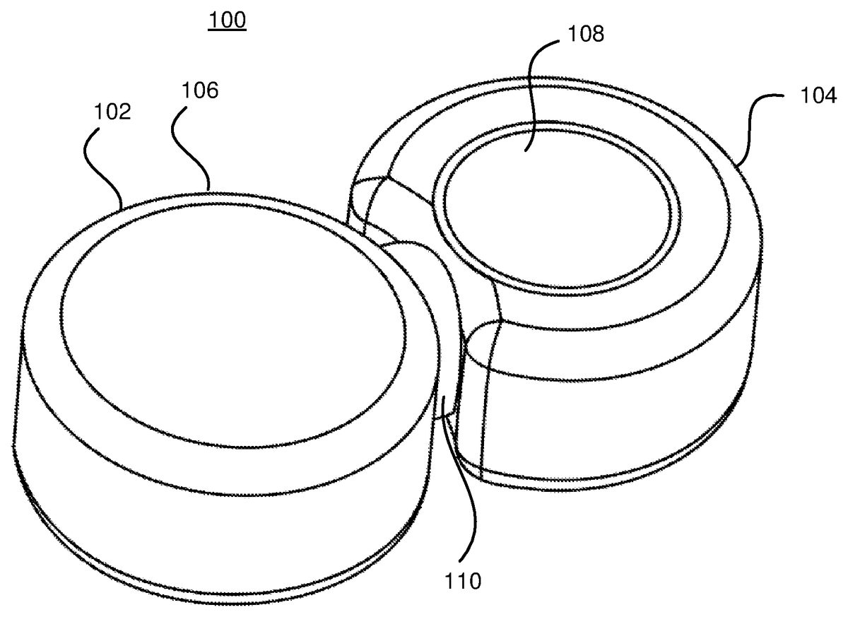
The present invention relates an input controller (100) for interacting with a virtual environment, and more specifically to an input controller comprising a first body (102) and a second body (104) connected to the first body, wherein the first body comprises a first input device (106) and the second body comprises a second input device (108). The first input device provides input control to the virtual environment with a first movement with at least 5 degrees of freedom in the virtual environment, the first movement being a relative movement, and the second input device provides input control to the virtual environment with a second movement with at least 2 degrees of freedom in the virtual environment, the second movement being an absolute movement.
Description
DETAILED DESCRIPTION OF EMBODIMENTS FIG. 1shows by way of example an input controller100according to embodiments of the invention. The input controller100comprises a first body102and a second body104. The first body102is coupled to the second body104via a flexible joint110. The first body102comprises a first input device106. In the embodiment shown inFIG. 1, the first input device is fixed to the first body such that a movement of the first body102means a movement of the first input device106. In the embodiment shown inFIG. 1the second body104provides a suspension device (not shown, seeFIG. 8-9for examples) for the suspension of the first body102extending on an inside of the first body102to a center of the first input device106. The suspension device may provide a suspension point substantially at a center of the first input device106for the resilient suspension of the first input device106, wherein the first origin is located at the suspension point. The first input device106may spring-back to the first origin when moved and released as a result of its suspension on the suspension device. As soon as forces start acting on the first body102and/or the second body104, the first input device106is arranged to move around the first origin with 6 degrees of freedom since the first body102will be moved and/or twisted in respect of the second body104via the suspension device. When used for controlling a virtual environment, the first input device100is arranged to interact with the virtual environment by a first movement with 6 degrees of freedom in the virtual environment. The first movement corresponds to a movement by the first input device106around the first origin in that a linear movement (in three directions, along the x-axis, along the y-axis and along the z-axis) and/or a rotating movement (in two or three directions, pitch, yaw, and optionally roll) of the first movement depends ...
DETAILED DESCRIPTION OF EMBODIMENTS
FIG. 1shows by way of example an input controller100according to embodiments of the invention. The input controller100comprises a first body102and a second body104. The first body102is coupled to the second body104via a flexible joint110. The first body102comprises a first input device106. In the embodiment shown inFIG. 1, the first input device is fixed to the first body such that a movement of the first body102means a movement of the first input device106. In the embodiment shown inFIG. 1the second body104provides a suspension device (not shown, seeFIG. 8-9for examples) for the suspension of the first body102extending on an inside of the first body102to a center of the first input device106. The suspension device may provide a suspension point substantially at a center of the first input device106for the resilient suspension of the first input device106, wherein the first origin is located at the suspension point. The first input device106may spring-back to the first origin when moved and released as a result of its suspension on the suspension device. As soon as forces start acting on the first body102and/or the second body104, the first input device106is arranged to move around the first origin with 6 degrees of freedom since the first body102will be moved and/or twisted in respect of the second body104via the suspension device.
When used for controlling a virtual environment, the first input device100is arranged to interact with the virtual environment by a first movement with 6 degrees of freedom in the virtual environment. The first movement corresponds to a movement by the first input device106around the first origin in that a linear movement (in three directions, along the x-axis, along the y-axis and along the z-axis) and/or a rotating movement (in two or three directions, pitch, yaw, and optionally roll) of the first movement depends on how the first body102and thus the first input device106is pushed and twisted around the first origin.
The first input device106is arranged to control the virtual environment with relative movements in the virtual environment. This means that as long as the first input device106is pushed/twisted, i.e. as long as it is not in the first origin, the first input device will provide controlling movements to the virtual environment. For example, if the virtual environment comprises a car which is controlled by the input controller100, a force (e.g. a push by a hand of a user) acting on the first input device106in the x-direction will result in a movement of the car in a corresponding direction of the virtual environment as long as the force continues to act on the first input device106. The speed or the acceleration of the movement of the car will depend on how far from the origin the first input device106is pushed by the force.
The second body104comprises a second input device108. The second input device108is arranged to control the virtual environment with absolute movements in the virtual environment. In the exemplary embodiment ofFIG. 1, the second input device108is a pressure pad108. The pressure pad108is located on top of the second body which is advantageous in that a user can control the pressure pad108by using his thumb when holding the input controller100. The pressure pad108is arranged for receiving an input in 2 degrees of freedom in respect of a second origin, wherein the second origin is located at a position on the pressure pad108in which a proceeding input was received by the pressure pad108. The preceding input for such a pressure pad may be when a sensor (not shown) of the pressure pad108first reads that e.g. a finger is pressed against the pressure pad108. Then for forming the second movement, new readings (i.e. a received input) are done by the sensor continuously with a fixed time interval between each reading) as long as the sensor reads that the finger is pressed towards the pressure pad. The distance the finger has moved between each reading and the direction of the movement of the finger is transformed to the second movement in an absolute way. This means that if the second movement controls the gear lever of the car, the gear lever will move in the direction in which the finger moves on the pressure pad108. The second movement thus corresponds to a received input of the pressure pad108in respect of the second origin. The displacement of the movement of the gear lever in that direction is based on a distance between a position of the received input, e.g. where the finger currently is sensed on the pressure pad108, and the second origin. If the finger is held still, the gear lever will stop moving. If the finger leaves the pressure pad108and then again is sensed by the sensor of the pressure pad, a new movement will begin, the old second origin will be disregarded and a new second origin will be located at the position on the pressure pad in which the finger first is sensed by the sensor.
The input controller100ofFIG. 1is symmetrically shaped. This may be advantageous since for ergonomically reasons. In the example embodiment ofFIG. 1, each of the first102and the second body104has a substantially cylindrical shape and the first body102is connected with the second body104such that the input controller100is shaped as an eight in cross section. This design makes it possible to turn the input control 180 degrees, if the user prefers to control the first input device with the right hand instead of the left. The preferences of the input controller100may allow for such rotation.
It should be noted that the pressure pad108may be replaced by any other device providing at least 2 degrees of freedom in respect of a second origin. For example, a trackball may be used. In this case, the user may control the displacement of the second movement by rotating of the trackball. In other words, an amount of rotation of the second input device relative the second origin controls the displacement of the second movement.
A game situation wherein the virtual environment of a game is controlled by the input controller100will now be described.
The player puts on a VR headset and pick up the input controller100. The player starts the game controlling the pointer with the pressure pad108. The player looks around by turning his head (the headset detects and relays the input to the game), move his body within the game freely in 6 DOF by pushing and/or twisting the first input device106. When encountering a bad guy, the player can aim fast and accurate with the pressure pad108controlling the cross-hair in 2D within the view. When the player is in a tight spot, he can do all these things at the same time; run away from an opponent by pushing the first input controller106forward, jump over an obstacle by pushing the first input controller106upwards and forwards, look over his shoulder by turning his head and the headset will relay that input, and aim accurately controlling the cross-hair (note; not the view) in the view with the pressure pad108.
The two most typical control situation a user is facing in a virtual 3D world is moving and aiming. Since the player is in an “endless” world a relative input is required for moving. Compare by using an absolute movement, e.g. a computer mouse where a movement by several meters may be needed. Using a relative input device, the user can move the first input device106a few millimeters in order to increase the velocity and reach the desired position. On the other hand when the user wants to do a quick movement with precision in a confined space, e.g. aiming a gun, an absolute movement may be a better alternative, since the movement in the 3D world corresponds to the movement in real life.
By providing a 5 or 6 DOF input device, i.e. the first input device106, the user can perform one natural movement, the first movement, and engaging just one hand. The second hand may then be free for providing the second movement. Compare this with using two or more 2D controllers, the user then have to combine 3 unnatural movements using both hands to perform the same movement in the 3D world.
FIG. 2describe a similar input controller200as the input controller100inFIG. 1. The difference between the input controller200and the input controller100ofFIG. 1is that the input controller200comprises a second pressure pad202located on top of the first body102. By this embodiment, a user can provide a third movement in the virtual environment, in the same way as the second movement described above in conjunction withFIG. 1. The second pressure pad202is advantageously positioned for easy access of the thumb of a user of the input controller200.
FIG. 3describe the 6 DOF of the movement of the first input device106in respect of the first origin. The first origin may according to some embodiments be placed in the centre of mass of the first body102. The first origin may according to some embodiments be placed in the centre of volume of the first body102. The first origin may according to some embodiments be placed in the centre of the suspension of the first body on the second body104. As shown inFIG. 3, the first body102, and thus the first input device106, can move forward/backward along the x-axis302, up/down along the z-axis306, and left/right along the y-axis304. The first body102thus can move via translation in all three perpendicular axes. The first body is also configured for rotation about the three perpendicular axes302,304,306. Such rotation is often termed pitch, yaw, and roll when translated into movements in the virtual environment. If a 5 DOF input device is used, the roll rotation may be omitted. According to some embodiments, another of the rotations is omitted, e.g. pitch or yaw.
FIG. 3also describe how a pressure pad108is arranged to receive an input in 2 degrees of freedom, i.e. along the perpendicular axis308,310. As described above, the second origin moves depending on where on the pressure pad the sensor of the pressure pad108first reads a touch from e.g. a finger of a user.
FIG. 4shows by way of example a third embodiment400of the input controller described herein. According to this embodiment, the first body102and the second body104are separate from each other but connected via a wire406configured to transmit data between the first106and the second108input device. Each of the first102and the second104body comprises an elongated handle portion402,404configured for holding by a single hand408,410of a user. In the embodiment ofFIG. 4, the first input device106is disposed at one end of the elongated handle portion402of the first body102. The first input device106is resiliently suspended, via a flexible joint110, on the elongated handle portion402of the first body102. The first body102may provide a suspension device for the suspension of the first input device106. The suspension device may comprise an end part shaped as a thin and flat object, e.g. a plate or a disc, or an end part having a spherical shape. The end part may be arranged substantially at the center of the first input device106. The first input device106may be suspended by a plurality of springs, such as three springs, such as four springs. The springs may be evenly spaced apart. The springs may be rigidly fixed to the first body102and the first input device106such that tension may build up in the springs as a result of a force applied to the first input device106. It is to be understood that a flexible material may be used to suspend the first input device106such that a similar function of tension build-up is achieved.
Alternatively, not shown inFIG. 4, the second body104may comprise a second input device, such as an accelerometer as described in conjunction withFIG. 5below, such that input in 3 degrees of freedom may be received. Hereby, absolute movement in 3 degrees of freedom relative a second origin may be sensed. The second origin may be set by a user by for instance pushing a button located on the input controller. The accelerometer may be placed in the elongated handle portion404.
This design makes it possible for a user to move the first input controller106in respect of the first origin with 6 DOF in a convenient way. The first origin may according to some embodiments be placed in the centre of mass of the first input device106. The first origin may according to some embodiments be placed in the centre of volume of the first input device106. The first origin may according to some embodiments be placed in the centre of the suspension of the first input device106on the elongated handle portion402of the first body102. The first input device is advantageously substantially shaped as a ball, possibly with its top cut off; this facilitates easy movement of the first input device106in respect of the first origin.
According to some embodiments, the second input device108is a pressure pad108positioned on the second body104proximate to a location of a thumb of the user's single hand410when the input controller400is held. The pressure pad108provides input control to the virtual environment as described above. It should be noted that the second input device instead may be arranged for receiving the input in 6 degrees of freedom in respect of the second origin by movement of the second body around the second origin. This means that when the user moves the second body around in the air (space), the second input device provides input control to the virtual environment via a second movement with 6 DOF. The second input device thus works as a Motion Controller, e.g. a Sony Move controller or a Nintendo Wii controller, by providing absolute movements to the virtual environment with 6 DOF. By moving the second body104, a user can accomplish position control by allowing position and movement tracking of the second body by the gaming system that relates to the player's movements and use these movements as inputs to the virtual environment, e.g. by using a gyroscope in the second body104. A further input device, e.g. a pressure pad, may be added to the second body, for example as described inFIG. 4. By directly connect the second body104with the first body102via a wire406for transmitting data between the first106and the second108input device, the two separate input devices106,108could advantageously share resources such as a processor, memory, Wi-Fi transceiver etc.
FIG. 5shows an input controller500which comprises the 5 or 6 DOF part of the input controller ofFIG. 4. The input controller500thus functions and is designed as the first body102ofFIG. 4. The input controller500comprises an elongated handle portion502configured for holding by a single hand508of a user. The first input device506is disposed at one end of the elongated handle portion402. The first input device506is resiliently suspended, via a flexible joint510, on the elongated handle portion502of the input controller500. The first input device506may be suspended on the elongated handle portion502by a suspension device of similar design and function as the suspension device described in conjunction withFIG. 4. The input controller500comprises a second input device, such as an accelerometer, such that input in 3 degrees of freedom may be received. Hereby, absolute movement in 3 degrees of freedom relative a second origin may be sensed. The second origin may be set by a user by for instance pushing a button located on the input controller500. The accelerometer may be placed in the elongated handle portion502.
FIG. 6shows a further embodiment of an input controller600. This input controller600is designed to be positioned on e.g. a table or another fixed surface, such as a body104of a laptop computer. InFIG. 6, the input controller600replaces the touch pad of a laptop. The first input device106may be resiliently suspended on a bottom surface of the input controller600. The pressure pad108functions as described above. The second body104may provide a suspension device of similar design and function as the suspension device described in conjunction withFIG. 4. The second body104may provide a suspension device for the suspension of the first input device106. The second body may be fixedly attached to the fixed surface, such as the body104of a laptop computer, such that the second input device108will not move when the first input device106moves. The first input device is thus a cylinder shaped device that encompasses the protruding part of the second body104, and is arranged to move around the protruding part, wherein the pressure pad108is located on a top surface of the protruding part.
FIG. 7describes an input controller700according to a fifth embodiment. The first body102and the second body104are integrally formed. The input controller700is configured for holding by a single hand of a user and moved on an underlying surface. The input controller700may for example be shaped as a computer mouse. By moving the input controller700on the underlying surface, an absolute input control may be provided to the virtual environment in the same way as an input provided by a regular computer mouse. In other words, the received input of the second input device108is based on a movement of the input controller700relative to the underlying surface. The second input device108may function as in a mechanical computer mouse or in an optical computer mouse. InFIG. 7, the bottom surface of the input controller700comprises a recess, and the first input device106is resiliently suspended in the recess. This provides easy access and controllability of the first input device106when the user holds the input controller700as a computer mouse. The input controller700inFIG. 7comprise a wire but may also be wireless. The input controller may comprise further input devices (not shown), such as buttons on top of the input controller.
FIG. 8describes an input controller according to a sixth embodiment. The second body104may provide a suspension device802for the suspension of the first body102. The suspension device802may comprise an end part804shaped as a thin and flat object, e.g. a plate or a disc. The end part804may be arranged substantially at the center of the first body102. The first body102may be suspended by a plurality of springs806, such as three springs, such as four springs. The springs806may be evenly spaced apart. The springs806may be rigidly fixed to the first and the second body102,104such that tension may build up in the springs806as a result of a force applied to the first and/or second body102,104. It is to be understood that a flexible material may be used to suspend the first body102such that a similar function of tension build-up is achieved.
FIG. 9describes an input controller according to a seventh embodiment comprising a suspension device with a similar function to the embodiment described inFIG. 8. The second body104may provide a suspension device802for the suspension of the first body102. The suspension device802may comprise an end part904having a spherical shape. The end part904may be arranged substantially at the center of the first body102. The first body102may be suspended by a plurality of springs906, such as three springs, such as four springs. The springs906may be evenly spaced apart. The springs906may be rigidly fixed to the first and the second body102,104such that tension may build up in the springs906as a result of a force applied to the first and/or second body102,104. It is to be understood that a flexible material may be used to suspend the first body102such that a similar function of tension build-up is achieved. The movement of the second body relative the first body may be detected by a sensor, such as a 3D-sensor as described in EP0920672B1 on pages 2-3, sections 0010-0014, 0016-0017, and 0021, and/or by PSD's (Position Sensing Devices) or similar. A situation wherein a virtual environment is advantageously controlled by the input controller700will now be described.
The user is opening up a spreadsheet with a mouse movement of the input controller (i.e. the second movement) and a click, as the user normally does with a computer mouse. The user then starts using the first input device106and zooms out to see the vast spreadsheet, pans around, locates the cell he is looking for and zooms in on that. The user then edits the cell by using the second input device108and any buttons on the input device700.
The user then open up a photo editor and pans, zooms and even rotates a photo with the first input device106, pick a tool using the second input device108, and edits the photo by continue using the second input device, or even with a connected stand alone input device such as a drawing pad.
It should be noted that according to some embodiments, the first input device may be configured to change between providing a relative input (and thus provide a relative movement to the virtual environment) and an absolute input (and thus provide an absolute movement to the virtual environment) by changing a configuration of the first input device.
The present invention has mainly been described above with reference to a few embodiments. However, as readily appreciated by a person skilled in the art, other embodiments than the ones disclosed above are equally possible within the scope of the invention, as defined by the appended patent claims.
As an example, the input controller in the embodiments ofFIGS. 1-7may comprise a sensor in accordance with the embodiments ofFIG. 8-9.
In summary, the present invention relates an input controller for interacting with a virtual environment, and more specifically to an input controller comprising a first body and a second body connected to the first body, wherein the first body comprises a first input device and the second body comprises a second input device. The first input device provides input control to the virtual environment with a first movement with at least 5 degrees of freedom in the virtual environment, the first movement being an relative movement, and the second input device provides input control to the virtual environment with a second movement with at least 2 degrees of freedom in the virtual environment, the second movement being an absolute movement.
Claims
- An input controller for interacting with a virtual environment, comprising: a first body and a second body connected to the first body, wherein the first body comprises: a first input device resiliently suspended on the input controller so as to spring-back to a first origin when moved and released, the first input device being arranged to move relative the first origin with at least 5 degrees of freedom and arranged to interact with the virtual environment by a first movement with at least 5 degrees of freedom in the virtual environment, the first movement corresponding to a movement by the first input device relative the first origin, wherein the first movement is a relative movement, wherein the second body comprises: a second input device being arranged for receiving an input in at least 2 degrees of freedom relative a second origin, the second input device being arranged to interact with the virtual environment by a second movement with at least 2 degrees of freedom in the virtual environment, the second movement corresponding to a received input of the second input device relative the second origin, wherein the second movement is an absolute movement, wherein the input controller further comprises a suspension device fixed to the input controller and extending on an inside of the first body to a center of the first input device, the suspension device providing a suspension point substantially at a center of the first input device for the resilient suspension of the first input device, wherein the first origin is located at the suspension point, and wherein the first body and the second body are separated such that the received input of the second input device relative the second origin is received without implicating movement of the first input device relative the first origin.
- The input controller according to claim 1 , wherein the suspension device comprises an end part substantially at the center of the first input device, and a plurality of springs attached to the end part, wherein the first input device is resiliently suspended on the input controller by being attached to the plurality of springs.
- The input controller according to claim 2 , wherein the end part has a spherical shape, and wherein the plurality of springs is attached to the surface of the spherical shaped end part in an evenly spread out fashion.
- The input controller according to claim 2 , wherein the end part is shaped as a thin and flat object, and wherein the plurality of springs is attached to one side of the end part in an evenly spread out fashion.
- The input controller according to claim 1 , wherein the suspension device is fixed to the second body.
- The input controller according to claim 1 , wherein the first origin is located substantially at the center of the first body.
- The input controller according to claim 1 , wherein the first input device is arranged to move around the first origin with at least 5 degrees of freedom by movements of the first body relative the second body.
- The input controller according to claim 1 , having a symmetrical design.
- The input controller according to claim 8 , wherein each of the first and the second body has a substantially cylindrical shape and wherein the first body is connected with the second body such that the input controller is shaped as an eight in cross section.
- The input controller according to claim 1 , wherein the second input device is a pressure pad and wherein the second origin is located at a position on the pressure pad in which a proceeding input was received by the pressure pad.
- The input controller according to claim 1 , wherein each of the first and the second body comprises an elongated handle portion configured for holding by a single hand of a user and wherein the first body is directly electrically connected to the second body via a wire.
- The input controller according to claim 11 , wherein the suspension device is fixed to the elongated handle portion of the first body.
- The input controller according to claim 11 , wherein the first input device is disposed at one end of the elongated handle portion of the first body, wherein the first input device is resiliently suspended on the elongated handle portion of the first body.
- The input controller according to claim 11 , wherein the second input device is a pressure pad positioned on the second body proximate to a location of a thumb of the user's single hand, when the input controller is held, and wherein the second origin is located at a position on the pressure pad in which a proceeding input was received by the pressure pad.
- The input controller according to claim 11 , wherein the second input device is arranged for receiving the input in 6 degrees of freedom relative the second origin by movement of the second body relative second origin, wherein the second origin is located at a position in space in which the second body was located when a proceeding input was received by the second input device.
- The input controller according to claim 1 , wherein the first body and the second body are integrally formed, and wherein the input controller is configured for holding by a single hand of a user and moved on an underlying surface, wherein the received input of the second input device is based on a movement of the input controller relative to the underlying surface.
- The input controller according to claim 16 , wherein the input controller has a recess in a surface of the input controller configured to be moved on the underlying surface, wherein the first input device is resiliently suspended in the recess.
- The input controller according to claim 1 , wherein the first body and the second body are integrally formed, wherein the second body comprises a protruding part, wherein the first input device is a cylinder shaped device that encompasses the protruding part of the second body, and is arranged to move around the protruding part, and wherein the second input device is a pressure pad located on a top surface of protruding part, and wherein the second origin is located at a position on the pressure pad in which a proceeding input was received by the pressure pad.
Disclaimer: Data collected from the USPTO and may be malformed, incomplete, and/or otherwise inaccurate.