U.S. Pat. No. 10,357,712
COMPUTER GAME CONTROLLER
Issue DateNovember 30, 2017
Illustrative Figure
Abstract
The subject of the invention is a computer game controller, comprising a base (1) placed on a fixed substrate, with a chassis (2) placed thereupon, of ergonomic shape adapted for resting the user's hand, with a number of function buttons (3) on the top surface, the function buttons (3) enabling programming their functions, the base (1) being connected with the chassis (2) by means of a sliding lever mechanism (4), situated substantially axially along the longitudinal axis of the base (1), providing tilting the chassis (2) relative to the base (1) in two opposite directions, and a sliding movement of the chassis (2) forward and rearward in relation to the base (1), and at least one front switch (5) and a corresponding front resistive element (6), at least one rear switch (5) and a corresponding rear resistive element (6), at least one left-side switch (5) and a corresponding left-side resistive element (6), and at least one right-side switch (5) and a corresponding right-side resistive element (6) so that during the sliding forward movement, the front resistive element (6) presses the front switch (5), during the sliding backward movement, the rear resistive element (6) presses the rear switch (5), on the left tilt, the left-side resistive element (6) presses the left-side switch (5), and during the right tilt, the right-side resistive element (6) presses the right-side switch (5).
Description
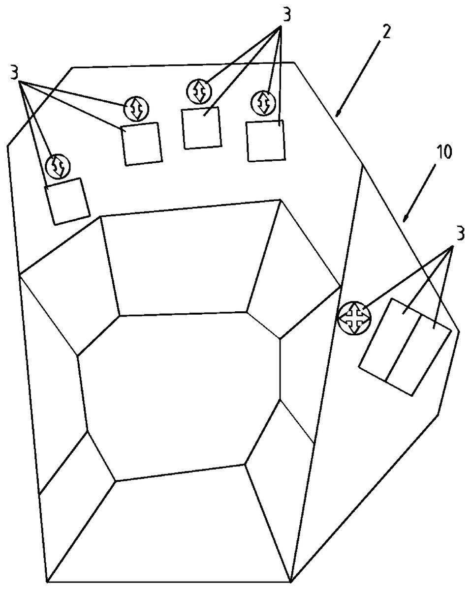
EXAMPLE 1 The first embodiment of the computer game controller according to the invention is illustrated inFIGS. 1-6. The taks of the computer game controller is to replace, first of all, the W, A, S, and D buttons of the computer keyboard, used to move the game character in FPP games, and other function keys, situated around the said W, A, S, D keys operated with the same player's hand. The presented computer game controller assumed a shape resembling a computer mouse. In this embodiment, a computer game controller adapted to the user's left hand is described. Of course, the computer game controller may by adapted to the user's right hand without departing from the protective aspect defined in the appended claims. The chassis2of the computer game controller has been contoured to have an ergonomic shape, enabling free positioning of the hand. There are 8 function keys3arranged on the chassis surface2, which are operated with the fingers of the palm resting on the controller. Function keys3are arranged so that they can be operated without the need to take away the whole hand from the computer game controller. In an alternative embodiment, there can be higher or lower number of function keys3, depending on the requirements of the given application. The number of function keys3situated on the external surface of chassis2does not constitute a limitation to the protective scope of this invention. In the presented embodiment, the chassis2comprises an additional replaceable lateral section10, as illustrated inFIG. 1, located on the right side of the main part of the chassis2, where additional function keys3have been deployed, operated with the user's thumb. The computer game controller according to the first embodiment of the present invention comprises a base1, placed on a flat surface, such as a desk. The base1, illustrated inFIG. 3, has ...
EXAMPLE 1
The first embodiment of the computer game controller according to the invention is illustrated inFIGS. 1-6. The taks of the computer game controller is to replace, first of all, the W, A, S, and D buttons of the computer keyboard, used to move the game character in FPP games, and other function keys, situated around the said W, A, S, D keys operated with the same player's hand. The presented computer game controller assumed a shape resembling a computer mouse. In this embodiment, a computer game controller adapted to the user's left hand is described. Of course, the computer game controller may by adapted to the user's right hand without departing from the protective aspect defined in the appended claims. The chassis2of the computer game controller has been contoured to have an ergonomic shape, enabling free positioning of the hand. There are 8 function keys3arranged on the chassis surface2, which are operated with the fingers of the palm resting on the controller. Function keys3are arranged so that they can be operated without the need to take away the whole hand from the computer game controller. In an alternative embodiment, there can be higher or lower number of function keys3, depending on the requirements of the given application. The number of function keys3situated on the external surface of chassis2does not constitute a limitation to the protective scope of this invention. In the presented embodiment, the chassis2comprises an additional replaceable lateral section10, as illustrated inFIG. 1, located on the right side of the main part of the chassis2, where additional function keys3have been deployed, operated with the user's thumb.
The computer game controller according to the first embodiment of the present invention comprises a base1, placed on a flat surface, such as a desk. The base1, illustrated inFIG. 3, has an elongated shape resembling the shape of a computer mouse, wherein the longitudinal axis substantially defines the middle of the base1. The base1and the chassis2are interconnected with a slidable lever mechanism4that has been divided into two sections in this embodiment of the invention, the front one situated near the front end of the game controller, and the rear one situated near the rear end of the controller. The sliding lever mechanism4has been situated along the longitudinal axis of the base1of the computer game controller. The cross-section of the control along the plane marked as B-B inFIG. 3, disclosing the structure of the sliding lever mechanism4, has been presented inFIG. 5. Each section of the sliding lever mechanism4comprises a cylindrical socket8mounted on the base1which a slidable cylindrical rod9fitted to the internal surface of the chassis2is inserted into. Such design provides tilting the chassis2relative to the base1and a sliding forward and backward movement of the chassis2relative to the base1. Between the sections of the sliding lever mechanism4, a switching mechanism has been made, consisting of a front switch5and a corresponding front resistive element6, a rear switch5and a corresponding rear resistive element6, a left switch5and a corresponding left resistive element6, and a right switch5and a corresponding right resistive element6. The implemented switches5can be any switches suitable for that purpose, known in the state of the art, such as digital switches or analogue switches, which does not constitute a limitation of this invention. During the sliding forward movement, the front resistive element6presses the front switch5, during the sliding backward movement, the rear resistive element6presses the rear switch5, on the left tilt, the left resistive element6presses the left switch5, and during the right tilt, the right resistive element6presses the right switch5. Such action of the controller provides the game character movement, replacing the classically used W, A, S, and D buttons of the computer keyboard. The left and the right switches5are situated on the internal surface of the chassis2, and their corresponding resistive elements6are situated on the base1. The front and the rear switches5are placed on a special supporting structure on the base1, whereas their corresponding resistive elements6are situated on the internal surface of the chassis2. The computer game controller has also been equipped with a left and a right spring element7, situated close to the first and the second switch5, which provide the return movement of the chassis2after the tilt to the left or to the right. Similarly, the spring elements7are provided for tilting the chassis2to the front and to the back, the spring elements7using common resistive elements6for the front and the rear switch5. Similarly, spring elements7have been used in order to provide the return movement for tilting chassis forwards and backwards in relation to the base1.
The computer game controller according to the present invention comprises also an electronic system that the function keys3and witches5are connected to in order to operate and send corresponding electric signals to the computer hardware that the said computer game controller is connected to. This way, the said computer game controller is a “plug and play” device that upon connection to the computer hardware reports as a computer keyboard. The connection to the computer hardware is provided in a wireless way, by means of Bluetooth standard.
Example 2
A computer game controller according to the second embodiment of the present invention is schematically illustrated in figures from 7 to 11. Particularly, the design and the principle of operation of the controller is convergent with that represented in Example 1. The computer game controller comprises a base1placed on a flat substrate. A sliding lever mechanism4is situated on the base, and serves as the element fixing the base1to the chassis2and providing tilting movements of the chassis2to the sides, and sliding movements forwards and backwards of the chassis relative to the base1. In this embodiment of the present invention, the sliding lever mechanism comprises a single cylindrical rod9fitted to the base1and a cylindrical socket8situated on the internal side of the chassis surface2, which is the best illustrated byFIGS. 8A and 8B. Analogically, there are function keys3arranged in the chassis, operated with the user's fingers. Additionally, there are also a front and a rear switches5situated on the base1(illustrated in the axonometric view inFIG. 7and in lateral cross-sections inFIGS. 11A and 11B) The front and the rear switches5are activated by the common resistive element6, connected with the sliding lever mechanism4.FIG. 11Aillustrates the lateral cross-section of the computer game controller in normal position, i.e. without tilting in any direction.FIG. 11Billustrates, in turn, the lateral cross-section of the computer game controller in slid forward position. On sliding the chassis2forward relative to the base1, concurrent sliding forward of the resistive element6is observed, which results in pressing the front switch5, and consequently, the computer game controller sends an appropriate signal to the receiver, e.g. a signal corresponding to the forward movement of the character. Similarly, on sliding the chassis2backwards relative to the base1, the resistive element6will press the rear switch5, resulting in sending an appropriate message to the receiver. The applied front and rear switches5can be any type of switches used in analogous solutions, without departing from the subject matter of this invention. In order to implement automatic return of the chassis2to the normal position on cessation of the shifting force in any direction, a spring mechanism14has been used, as presented in the axonometric view inFIG. 7and in lateral cross-sections inFIGS. 10A and 10B. The spring mechanism14comprises a cam element15equipped with a socket and a key16of the shape corresponding to the said socket in the cam element15. The cam element15is attached to the base by means of a suitable spring, which causes pressing the cam elements15towards the base1.FIG. 10Aillustrates a lateral cross-section of a second embodiment of the computer game controller in its normal position (when no force acts upon it). In this situation the key16the spring mechanism14, connected with the sliding lever mechanism4, is situated in the cam element15socket.FIG. 10Billustrates the computer game controller with the chassis slid forward. In this situation, an appropriate forward shift of key16took place, which moving outside the cam element socket15caused the latter to slide upwards, and in consequence pressing the fixing spring. This resulted in creation of even greater force pressing the cam element15towards the base1, thus, taking into account the geometry of the key16and the cam element15socket, increasing the force forcing the return of the chassis2to the normal position, in particular after the cessation of the force causing its shift. The spring mechanism14will behave similarly on sliding the chassis2in the opposite direction, i.e. backwards, in relation to the base1. The implementation of the sliding lever mechanism4, like in example 1, additionally provided a tilting movement of the chassis2to the sides in relation to the base1. This situation is best illustrated byFIG. 8A, illustrating the controller cross-section in normal position, andFIG. 8B, illustrating the controller cross-section in the chassis2position tilted to the left relative to the base1.FIGS. 8A and 8Bbest illustrated the spring mechanism11providing the return to the normal position on cessation of the force tilting the chassis2. Like for the sliding movement, the spring mechanism11is implemented by means of a cam element12, equipped with a socket and a key13. This time, the key13is seated on a spring forcing the pressure directed to the base1.FIG. 8Aillustrates the controller in normal position. In this case the key13rests in the socket of the cam element12. On tilting in any direction, e.g. to the left, as illustrated inFIG. 8B, the key13, due to being seated on a spring, moves upwards causing the cam element12leave the socket, causing by the same increase of the force pressing the key13towards the base1, which increases the force forcing the return of chassis2to the normal position. After the pressing force ceases, the rounded shape of the key13makes it slide into the socket of the cam element12and in the result, the return of the cam element12and the whole chassis2to the normal position. The spring mechanism11implements similar operations on tilting into the other side.FIGS. 9A, 9B and 9Cillustrate the top view of the base1(without chassis2), respectively in normal position, tilted to the left, and tilted to the right. In the normal position, the common resistive element6, fitted to the cam element12, remains in central position between the respective left and right switches5, without activating either of them. On tilting the chassis2to the left (FIG. 9B), the resistive element6is also displaced to the left, causing the activation of the left switch5. Similarly, on tilting the chassis2to the right (FIG. 9C), the resistive element6moves to the right, causing the activation of the right switch5. The return to the normal position is provided by the spring mechanism11as described above. Other structural elements of the computer game controller according to the second embodiment of the present invention, like electronic systems, connection interfaces, etc., are consistent with the elements presented in Example 1, which provides full functionality of the presented device.
Claims
- A computer game controller, comprising a base placed on a fixed substrate, with a chassis placed thereupon, of ergonomic shape adapted for resting the user's hand, with a number of function buttons on the top surface, the function buttons enabling programming their functions, characterized in that the base is connected with the chassis by means of a sliding lever mechanism, situated substantially axially along the longitudinal axis of the base, providing tilting the chassis relative to the base in two opposite directions, and a sliding movement of the chassis forward and rearward in relation to the base, and at least one front switch and a corresponding front resistive element, at least one rear switch and a corresponding rear resistive element, at least one left-side switch and a corresponding left-side resistive element, and at least one right-side switch and a corresponding right-side resistive element so that during the sliding forward movement, the front resistive element presses the front switch, during the sliding backward movement, the rear resistive element presses the rear switch, on tilting to the left, the left-side resistive element presses the left-side switch, and on tilting to the right, the right-side resistive element presses the right-side switch.
- The computer game controller according to claim 1 , characterized in that at least one of the front switch and the rear switch are located on the base, and at least one of the corresponding front resistive element and the corresponding rear resistive element, respectively, are situated on the interior surface of the chassis.
- The computer game controller according to claim 1 , characterized in that at least one of the front switch and the rear switch are located on the interior surface of the chassis, and at least one of the corresponding front resistive element and the corresponding rear resistive element, respectively, are situated on the base.
- The computer game controller according to claim 1 , characterized in that at least one of the left-side switch and the right-side switch are located on the interior surface of the chassis, and at least one of the corresponding left-side resistive element and the corresponding right-side resistive element, respectively, are situated on the base.
- The Computer game controller according to claim 1 , characterized in that at least one of the left-side switch and the right-side switch are located on the base, and at least one of the corresponding left-side resistive element and the corresponding right-side resistive element, respectively, are situated on the interior surface of the chassis.
- The computer game controller according to claim 1 , characterized in that the front resistive element and the rear resistive element are connected to each other and form a common resistive element.
- The computer game controller according to claim 1 , characterized in that the left-side resistive element and the right-side resistive element are connected to each other and form a common resistive element.
- The computer game controller according to claim 1 , characterized in that it additionally comprises at least one of a front spring mechanism and a rear spring mechanism.
- The computer game controller according to claim 1 , characterized in that it additionally comprises at least one of a left-side spring mechanism and a right-side spring mechanism.
- The computer game controller according to claim 1 , characterized in that it additionally comprises at least one spring mechanism.
- The computer game controller according to claim 10 , characterized in that the spring mechanism comprises a cam element equipped with a socket and a key situated in the socket of the cam element.
- The computer game controller according to claim 11 , characterized in that at least one of the cam element and the key are seated on the fixing spring.
- The computer game controller according to claim 1 , characterized in that the sliding lever mechanism comprises a cylindrical socket mounted on the base, which is a slidable cylindrical rod fitted to the internal surface of the chassis is inserted into.
- The computer game controller according to claim 1 , characterized in that the sliding lever mechanism comprises a cylindrical socket fitted to the internal surface of the chassis, which is a slidable rod fitted to the base is inserted into.
- The computer game controller according to claim 1 , characterized in that the sliding lever mechanism is divided into two sections situated near opposite ends of the computer game controller along its longitudinal axis.
- The computer game controller according to claim 1 , characterized in that the chassis additionally comprises a lateral section, where additional function keys are located.
- The computer game controller according to claim 1 , characterized in that it comprises a wireless interface for communication with computer hardware.
Disclaimer: Data collected from the USPTO and may be malformed, incomplete, and/or otherwise inaccurate.