U.S. Pat. No. 10,350,487
METHOD AND APPARATUS FOR AUTOMATICALLY TARGETING TARGET OBJECTS IN A COMPUTER GAME
AssigneeWE MADE IO CO., LTD.
Issue DateDecember 9, 2015
Illustrative Figure
Abstract
A method of automatically targeting a target object, the method including setting a target range including a designated distance from a user-controlled character and a designated horizontal angle centering at a location of the character, selecting at least one target object included in the set target range, and displaying a shape distinguishable from a shape of the target object at a location near the at least one selected target object, wherein the target object is an object the character is able to attack from among objects in a computer game.
Description
One or more aspects of the presently disclosed embodiment include a method of automatically targeting a target object in a computer game by using a designated distance from a location of a user-controlled character and a horizontal angle around the location of the character. Additional aspects will be set forth in part in the description which follows and, in part, will be apparent from the description, or may be learned by practice of the presented aspects. DETAILED DESCRIPTION According to one or more aspects of the presently disclosed embodiment, a method of targeting a target object, the method includes setting a targeting range including a designated distance from a user-controllable character and a designated horizontal angle centering at location of the character; selecting at least one target object included in the set targeting range; and displaying a shape distinguishable from shape of the target object at a location nearby the selected target object, wherein the target object refers to an object the character is able to attack from among objects in a computer game. According to one or more aspects of the presently disclosed embodiment, a method of targeting at least one object in a computer game, the method includes combining a first user-controlled character with a second character based on first input information from a user; setting a targeting range of the first character based on moving information regarding the second character; determining whether the object is within the set targeting range based on second input information from the user; and displaying an image indicating that an object is targeted based on a result of the determination. According to one or more aspects of the presently disclosed embodiment, an apparatus for executing a computer game, the apparatus includes a setting unit, which sets a targeting range including a designated ...
One or more aspects of the presently disclosed embodiment include a method of automatically targeting a target object in a computer game by using a designated distance from a location of a user-controlled character and a horizontal angle around the location of the character.
Additional aspects will be set forth in part in the description which follows and, in part, will be apparent from the description, or may be learned by practice of the presented aspects.
DETAILED DESCRIPTION
According to one or more aspects of the presently disclosed embodiment, a method of targeting a target object, the method includes setting a targeting range including a designated distance from a user-controllable character and a designated horizontal angle centering at location of the character; selecting at least one target object included in the set targeting range; and displaying a shape distinguishable from shape of the target object at a location nearby the selected target object, wherein the target object refers to an object the character is able to attack from among objects in a computer game.
According to one or more aspects of the presently disclosed embodiment, a method of targeting at least one object in a computer game, the method includes combining a first user-controlled character with a second character based on first input information from a user; setting a targeting range of the first character based on moving information regarding the second character; determining whether the object is within the set targeting range based on second input information from the user; and displaying an image indicating that an object is targeted based on a result of the determination.
According to one or more aspects of the presently disclosed embodiment, an apparatus for executing a computer game, the apparatus includes a setting unit, which sets a targeting range including a designated distance from a user-controllable character and a designated horizontal angle centering at location of the character; selecting unit, which selects at least one target object included in the set targeting range; and a display unit, which displays a shape distinguishable from shape of the target object at a location nearby the selected target object.
According to one or more aspects of the presently disclosed embodiment, an apparatus for executing a computer game, the apparatus includes a combining unit, which combines a first user-controlled character with a second character based on first input information from a user; a setting unit, which sets a targeting range of the first character based on moving information regarding the second character; a determining unit, which determines whether the object is within the set targeting range based on second input information from the user; and a display unit, which displays an image indicating that an object is targeted based on a result of the determination.
Reference will now be made in detail to aspects, examples of which are illustrated in the accompanying drawings, wherein like reference numerals refer to like elements throughout. In this regard, the presently disclosed embodiment may have different forms and should not be construed as being limited to the descriptions set forth herein. Accordingly, the aspects are merely described below, by referring to the figures, to explain aspects of the present description. As used herein, the term “and/or” includes any and all combinations of one or more of the associated listed items.
As the disclosed embodiment allows for various changes and numerous aspects, particular aspects will be illustrated in the drawings and described in detail in the written description. However, this is not intended to limit the presently disclosed embodiment to particular modes of practice, and it is to be appreciated that all changes, equivalents, and substitutes that do not depart from the spirit and technical scope of the presently disclosed embodiment are encompassed in the presently disclosed embodiment. In the description of the presently disclosed embodiment, certain detailed explanations of related art are omitted when it is deemed that they may unnecessarily obscure the essence of the disclosed embodiment.
In aspects of the presently disclosed embodiment, the terms “communication”, “communication network”, and “network” may be synonyms. These terms refer to a narrow area communication network or a broad area comment network capable of transmitting and receiving files between a user terminal and a server via wires or wirelessly.
Hereinafter, the term “server” refers to a server computer that users access to use game content. In small games or games with a small number of users, a plurality of game programs may be operated at a single game server. On the other hand, in a very large game or a game with a large number of users simultaneously accessing the game, there may be more than one server for operating a single game. Furthermore, middleware regarding databases or servers for processing payments may be connected to a game server. However, descriptions thereof will be omitted below.
Hereinafter, the term “computer game” refers to game content that users may use by accessing the game server. Particularly, the term “computer game” refers to a computer game, in which a plurality of users may simultaneously play and upgrade levels of characters by training characters or obtaining experience points. Furthermore, the term “computer game” refers to a computer game, in which users may purchase various types of items for smooth gameplay.
Furthermore, various group communities may be used in a computer game. For example, guilds or clans in a computer game may be formed. The terms “guild” or “clan” refers to groups or organizations organized by users playing particular computer games. The reputation of each organization may be improved based on the number of users therein or levels of characters of the users therein, and various benefits in the computer game may be given based on the reputation. For example, if the reputation of a guild or a clan improves, characters thereof may be displayed differently (e.g., names of characters thereof may be changed) or benefits regarding items or facilities in the computer game may be given to characters thereof.
Furthermore, group communities available in a computer game also include party play. The term “party” is an in-game group formed as users invite one another and accept invitations, where members of a formed party may use a dedicated chatting system or a particular marking for identifying party members in a game screen image.
Furthermore, members of a party may distribute items to one another or share result content obtained as a result of playing the game. It may be set to equally distribute result content to each of members or to distribute at least portions of result content to other members.
Hereinafter, the term ‘result content’ refers to all content that may be obtained by characters of users as a result of playing a game. For example, in a shooting game, experience and cyber money that can be obtained when a single game is over may be included in result content. In a sports game, experience and cyber money that can be obtained when a single game is over may be included in result content. In case of an RPG game, experience and compensation cyber money that can be obtained when a particular quest is completed or a monster is killed may be result content.
FIG. 1is a diagram of a system100for playing a computer game according to an aspect of the presently disclosed embodiment.
FIG. 1shows examples of terminals including a desktop or laptop PC110and a mobile or smartphone120, where the terminals are connected to a server140via a network130and perform tasks.
Here, the network130may include the Internet, a local area network (LAN), a wireless LAN, a wide area network (WAN), and a personal area network (PAN). However, the presently disclosed embodiment is not limited thereto, and the network130may include other types of networks via which data may be transmitted and received. In aspects described below, it will be assumed that data transmission and reception between the terminal and the server140are performed via the network130. However, the presently disclosed embodiment is not limited thereto.
Furthermore, a smartphone, including a touch screen, will be provided as an example of the mobile or smartphone120. However, any other device capable of accessing the server140via the network130and performing tasks may be applied.
Here, a touch screen refers to a display screen to which designated information may be input via ‘gestures’ of a user. For example, gestures stated below may include a tap, a touch & hold, a double-tap, a drag, a pan, a flick, a drag-and-drop, etc.
Hereinafter, although it is assumed in the description below that a terminal for performing a method of targeting a target object, according to an embodiment of the presently disclosed embodiment, is the desktop or laptop PC110, one of ordinary skill in the art will understand that the method may also be performed by the mobile or smartphone120. Hereinafter, the desktop or laptop PC110is referred to as the terminal110.
Furthermore, although it is assumed that data for performing a method of obtaining a sub-character described below with reference toFIG. 2 through 16is mainly processed by the terminal110, one of ordinary skill in the art will easily understand that the terminal110may perform a user interface (UI) function and a display function and data may be processed by the server140.
For example, the terminal110may receive information required for proceeding a game from a user and may transmit the information to the server140via the network130. Next, the server140may process data as described below by using the transmitted information and may transmit a result of processing the data to the terminal110via the network130. Next, the terminal110may display the transmitted result of processing the data on a display screen of the terminal110.
In addition, one of ordinary skill in the art will easily understand that the terminal110and the server140may appropriately share data processing for proceeding a computer game. In other words, the terminal110and the server140connected to each other via the network130may organically process data like one processor or a plurality of processors that are connected to one another.
For example, the terminal110may include a setting unit for setting a target range including a designated distance from a user-controlled character and a horizontal angle around a location of the character, a selecting unit for selecting at least one target object included in a set target range, and a display unit for displaying a shape distinguished from a shape of the target object at a location adjacent to the selected target object.
As another example, the terminal110may include a combining unit, the setting unit, a determining unit, and the display unit. In detail, the combining unit of the terminal110combines a first character controlled by a user with a second character based on first information input by the user. Furthermore, the setting unit of the terminal110determines a target range of the first character based on moving information of the second character. Furthermore, the determining unit of the terminal110determines whether a designated object is in a set target range based on second input information from the user. Furthermore, the display unit of the terminal110displays an image indicating that the object is targeted based on a result of the determination.
Here, each of the selecting unit, the combining unit, the setting unit, the determining unit, and the display unit included in the terminal110may be embodied by one processor or a plurality of processors. A processor may be embodied as an array of a plurality of logic gates or a combination of a general purpose microprocessor and a memory storing a program to be executed by the microprocessor. Furthermore, one of ordinary skill in the art will understand that the selecting unit, the determining unit, and/or the converting unit may be embodied in any of various other types of hardware.
Hereinafter, referring toFIGS. 2 through 10, a method of targeting a target object according to an aspect of the presently disclosed embodiment will be described in detail. The setting unit, the selecting unit, and the display unit as described above may perform operations of a method targeting an object.
Hereinafter, an example of a method of targeting an object will be described with reference toFIGS. 7A, through8andFIGS. 11 through 16. The combining unit, the setting unit, the determining unit, and the display unit as described above may perform operations of a method of targeting an object.
FIG. 2is a flowchart of a method of targeting a target object, according to an aspect of the presently disclosed embodiment.
Referring toFIG. 2, the method of targeting a target object includes operations that are chronologically performed by the terminal or the server140shown inFIG. 1. Therefore, even though omitted below, descriptions above of the terminal or the server140shown inFIG. 1may also be applied to the method of obtaining a sub-character as shown inFIG. 2.
In operation210, the terminal (110ofFIG. 1) sets a target range including a designated distance from a user-controlled character and a designated horizontal angle around a location of the character. In detail, the setting unit of the terminal (110ofFIG. 1) sets a target range including a designated distance from a user-controlled character and a designated horizontal angle around a location of the character.
Here, the target object is an object that can be attacked by a character from among objects in a computer game. For example, a target object may be a monster in a computer game or another character controlled by another user. However, the presently disclosed embodiment is not limited thereto, and the target object may include any target that can be attacked by a character.
Hereinafter, a target range according to an aspect of the presently disclosed embodiment will be described.
FIGS. 5A and 5Bare diagrams showing target ranges according to an aspect of the presently disclosed embodiment.
FIG. 5Ashows an example of a designated distance from a character and a designated horizontal angle around a location of the character, which constitute a target range. Furthermore,FIG. 5Bshows an example of a target object included in a target range.
Referring toFIG. 5A, a user-controlled character510(hereinafter, referred to as the character510) and a target object530are shown. Here, the target object530is an object that can be attacked by the character510from among objects in a computer game and may be a monster, for example.
The terminal (110ofFIG. 1) sets a target range including a designated distance a from the character510and a designated horizontal angle θ around a location of the character510.
The designated distance a from the character510is a distance in a direction that is parallel to a direction that the character510faces from a location of the character510in a computer game. For example, the designated distance a may be 20 m. However, the presently disclosed embodiment is not limited thereto. Furthermore, designated horizontal angle θ around the location of the character510is a central angle in a horizontal direction. For example, the designated horizontal angle θ may be 180°. However, the presently disclosed embodiment is not limited thereto.
When the designated distance a and the designated horizontal angle θ are determined, a target range520, including the determined designated distance a and the determined designated horizontal angle θ, may be set. Therefore, the terminal (110ofFIG. 1) may set the target range520by setting the designated distance a and the designated horizontal angle θ.
Referring toFIG. 5A, the target range520is displayed distinguishably from the surroundings. However, the presently disclosed embodiment is not limited thereto. In other words, the target range520may not be displayed on the display screen of the terminal (110ofFIG. 1).
In addition, the target range520may be determined based on a type of an equipment item set to the character510. Here, the target range520is a range in which the effect of an equipment item is applied, whereas the target object530is a target object included in a range in which the effect of an equipment item is applied.
For example, comparing a case in which an equipment item set to the character510is a ‘bow’ to a case in which an equipment item set to the character510is a ‘sword’, a longer range attack may be performed in the case in which the character510is equipped with the ‘bow’ than in the case in which the character510is equipped with the ‘sword’. In other words, when the character510is equipped with a ‘bow’, even the target object530that is far away from the character510can be attacked. Therefore, the target range520of the case in which the character510is equipped with a ‘bow’ may be larger than the target range520of the case in which the character510is equipped with a ‘sword’.
Here, the designated distances a and the designated horizontal angles θ constituting the target range520may be pre-set with respect to types of equipment items. For example, if an equipment item is a ‘bow’, the designated distance may be set to 30 m and the horizontal angle may be set to 180° in advance. On the other hand, if an equipment item is a ‘sword’, the designated distance may be set to 3 m and the horizontal angle may be set to 90° in advance. Therefore, every time a user changes an equipment item set to the character510, the target range520may be changed based on a pre-set designated distance a and a pre-set horizontal angle θ.
In addition, the horizontal angle θ may also refer to an angle formed by a location of the character510and two different locations selected based on information input by a user. In other words, as described above, the designated horizontal angle θ may be changed based on an equipment item set to the character510or based on information input by a user.
Here, an example that the horizontal angle θ is changed based on information input by a user will be described below with reference toFIG. 6.
FIG. 6is a diagram of an example that the horizontal angle θ is changed based on information input by a user.
Referring toFIG. 6, two different locations630and640that are selected based on information input by a user and a target range650are displayed. Here, the information input by a user is information input via a UI unit included in the terminal (110ofFIG. 1). Therefore, the information input by a user is information regarding the two different locations630and540input is the UI unit.
Here, a UI unit is a module which obtains information input by a user and displays output information to the user. For example, a UI unit my include both input and output devices, such as a display panel, a mouse, a keyboard, a touch screen, a monitor, and a speaker, and software modules for driving the same.
When a user selects the two different locations630and640is the UI unit, the terminal (110ofFIG. 1) (in detail, the setting unit of the terminal (110ofFIG. 1)) sets an angle θ′ formed by a location620of a character610and the two differently selected locations630and640as a horizontal angle. Next, the terminal (110ofFIG. 1) may select an area formed by the location620of the character610and the two differently selected locations630and640as the target range650.
Here, the set horizontal angle θ may be included in a range of horizontal angles θ that are pre-set based on types of equipment items set to the character610. For example, if the character610is equipped with a ‘bow’ and a horizontal angle θ that is pre-set to the ‘bow’ is 180°, a horizontal angle set by the two different locations630and640selected by a user may be within 180°. Therefore, if the angle θ′ formed by the location620of the character610and the two different locations630and640exceeds 180°, the terminal (110ofFIG. 1) limits the angle θ′ to be within 180°.
Furthermore, the target range650, which is an area formed by the location620of the character610and the two different locations630and640, may be included in a target range that is pre-set based on a type of an equipment item set to the character610. For example, if it is assumed that an equipment item set to the character610is a ‘bow’, the target range650set based on the two different locations630and640selected by a user must be included in a target range formed by a designated distance and a target range that are pre-set to the ‘bow’. Therefore, if the target range650formed by the location620of the character610and the two different locations630and640exceeds a pre-set target range, the terminal (110ofFIG. 1) limits the target range650to be within the pre-set target range.
Referring toFIG. 5B, a target object560included in a set target range550is shown. If the target object560moves into the target range550of a character540, the terminal (110ofFIG. 1) automatically sets the target object560as a target to be attacked by the character540.
Referring back toFIG. 2, in operation220, the terminal (110ofFIG. 1) selects at least one target object included in a set target range. In detail, the selecting unit of the terminal (110ofFIG. 1) selects at least one target object included in a set target range.
Objects shown in a computer game may include objects that a character of a user can attack and objects that a character of a user cannot attack. Here, the objects that a character of a user can attack (that is, target objects) may include monsters and enemy characters controlled by other users, whereas the objects that a character of a user cannot attack may include animals, plants, or terrain features in the background.
The terminal (110ofFIG. 1) selects objects that a character of a user can attack (that is, target objects) from among objects included in a set target range, where the number of selected target objects is not limited.
In operation230, the terminal (110ofFIG. 1) displays a shape distinguishable from shapes of target objects at a location on the display screen of the terminal (110ofFIG. 1) that is near the selected target objects. In detail, the display unit of the terminal (110ofFIG. 1) displays a shape distinguishable from shapes of target objects at a location on the display screen of the terminal (110ofFIG. 1) that is near the selected target objects.
Here, the shape distinguishable from shapes of target objects may be any shape as long as the shape indicates that target objects are included in a target range. Hereinafter, an example of shapes that are distinguishable from shapes of target objects will be described with reference toFIGS. 7A and 7B.
FIGS. 7A and 7Bare diagrams showing shapes that are distinguishable from shapes of target objects, according to an aspect of the presently disclosed embodiment.
FIG. 7Ais a screen image displayed on the display screen of the terminal (110ofFIG. 1) when a target object710is not in a target range, whereasFIG. 7Bis a screen image displayed on the display screen of the terminal (110ofFIG. 1) when the target object710is in a target range.
Referring toFIG. 7A, if the target object710is not in a target range, no additional shape other than shape of the target object710is displayed. However, referring toFIG. 7B, if the target object710is in a target range as the target object710or a character of a user moves, a shape720that is distinguishable from the shape of the target object710is displayed at a location near the target object710. Therefore, the user may recognize that the target object710is in a target range and may attack the target object710by using an equipment item set to a character.
In addition, the terminal (110ofFIG. 1) (in detail, the display unit of the terminal (110ofFIG. 1)) continuously displays the shape720that is distinguishable from shapes of the target objects710for a time that the selected target objects710are included in a target range. Detailed descriptions thereof will be given below with reference toFIG. 8.
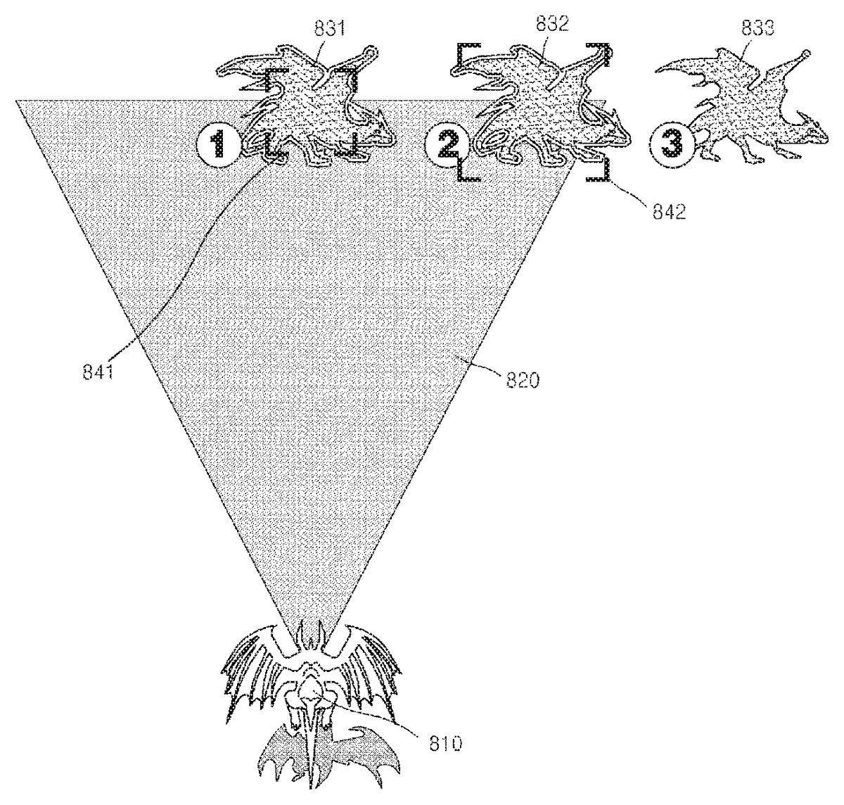
FIG. 8is a diagram showing an operation of the terminal (110ofFIG. 1) (in detail, the display unit of the terminal (110ofFIG. 1)), according to an aspect of the presently disclosed embodiment.
Referring toFIG. 8, a character810and target objects831,832, and833passing through a target range820are shown. Here, the target objects831,832, and833are not three different target objects. Instead, the target objects831,832, and833are a single target object831,832, and833that passes through the target range820according to lapse of time.
The terminal (110ofFIG. 1) continuously displays shapes841and842that are distinguishable from shapes of the target objects831and832during a time that the selected target objects831and832are in the target range820. In detail, inFIG. 8, the reference numerals831and832indicate a case in which a target object is in the target range820, whereas the reference numeral833indicates that the target object moved out of the target range820. The terminal (110ofFIG. 1) (in detail, the display unit of the terminal (110ofFIG. 1)) continuously displays the shapes841and842that are distinguishable from shapes of the target objects831and832during a time that the selected target objects831and832are in the target range820, thereby notifying a user that the target objects831and832can be attacked from a current location of the character810.
In addition, the shapes841and842that are distinguishable from shapes of the target objects831and832may differ based on the locations of the target objects831and832in the target range820. In detail, if the target object831is located near the center of the target range820, the target object831cannot move out of the target range820within a short time. Here, the terminal (110ofFIG. 1) displays the shape841that is distinguishable from a shape of the target object831to be small, thereby notifying a user that the target object831cannot move out of the target range820within a short time.
Furthermore, if the target object832is located near a boundary of the target range820, the target object832will move out of the target range820within a short time. Here, the terminal (110ofFIG. 1) displays the shape842that is distinguishable from the shape of the target object832to be large, thereby notifying a user that the target object832will move out of the target range820within a short time.
As described above, since the terminal (110ofFIG. 1) automatically targets target objects included in a designated range, a user does not have to operate the terminal (110ofFIG. 1) to target a target object. As a result, user convenience and concentration on a computer game may be improved. Furthermore, since the terminal (110ofFIG. 1) automatically recognizes and targets a target object appearing at a long range, a user may play a computer game more easily.
FIG. 3is a flowchart of a method of targeting a target object, according to another aspect of the presently disclosed embodiment.
Referring toFIG. 3, the method of targeting a target object includes operations that are chronologically performed by the terminal or the server140shown inFIG. 1. Therefore, even though omitted below, descriptions above of the terminal or the server140shown inFIG. 1and the method described above with reference toFIG. 2may also be applied to the method of targeting a target object, as shown inFIG. 3.
In addition, operations310and320shown inFIG. 3correspond to operations210and220described above with reference toFIG. 2, respectively. Therefore, detailed descriptions thereof will be omitted.
In operation330, if two or more target objects are selected, the terminal (110ofFIG. 1) determines priorities of the target objects based on their respective distances between the target objects and a character. Here, the priorities are priorities for a user to attack by using a character. For example, the terminal (110ofFIG. 1) may determine priorities of target objects based on distances from a location of a character.
Furthermore, if there is a target object selected by information input by a user, the terminal (110ofFIG. 1) may determine priorities of target objects by setting the highest priority to the target object selected based on information input by a user.
For example, it is assumed that the total number of target objects included in a target range is 3, a first target object is the closest object to a location of a character, a second target object is the second closest object to the location of the character, and a third target object is the farthest object from the location of the character. Furthermore, it is assumed that a user selected the second character separately via a UI unit. Here, a user may select the second character separately by clicking on a shape corresponding to the second character by using a mouse included in the terminal (110ofFIG. 1). However, the presently disclosed embodiment is not limited thereto.
Here, if priorities of target objects are determined based on their respective distances between target objects and a character, the priorities are determined in the order of ‘the first target object→the second target object→the third target object’. However, since the user selected the second target object, the terminal (110ofFIG. 1) determines priorities of the target objects in the order of ‘the second target object→the first target object→the third target object’.
In operation340, the terminal (110ofFIG. 1) displays different shapes at locations near the selected target objects in correspondence to the priorities determined in operation330. For example, if priorities of target objects are determined in the order of ‘the second target object→the first target object→the third target object’, the terminal (110ofFIG. 1) displays a shape, which is larger or brighter than shapes to be displayed at locations near shapes of the first target object and the third target object, at a location near the shape of the second target object. Therefore, a user may recognize which of the target objects included in a target range needs to be attacked first and play a computer game based on the recognition.
FIG. 4is a flowchart of a method of targeting a target object, according to another aspect of the presently disclosed embodiment.
Referring toFIG. 4, the method of targeting a target object includes operations that are chronologically performed by the terminal or the server140shown inFIG. 1. Therefore, even though omitted below, descriptions above of the terminal or the server140shown inFIG. 1and the methods described above with reference toFIGS. 2 and 3may also be applied to the method of targeting a target object as shown inFIG. 4.
In addition, operation410shown inFIG. 4corresponds to operation210described above with reference toFIG. 2. Therefore, detailed descriptions thereof will be omitted.
In operation420, the terminal (110ofFIG. 1) sets at least one area based on a designated radius range centering at a character. In detail, the terminal (110ofFIG. 1) divides a target range set in operation410into at least one area based on a designated radius range. Detailed descriptions thereof will be given below with reference toFIG. 9.
FIG. 9is a diagram showing an example that the terminal (110ofFIG. 1) according to an aspect of the presently disclosed embodiment divides a target range into at least one area.
Referring toFIG. 9, a user-controlled character910(hereinafter, referred to as the character910) and a target range920are shown. AlthoughFIG. 9shows that the target range920is divided into three areas921,922, and923, the presently disclosed embodiment is not limited thereto. In other words, as long as the target range920is divided into two or more different areas, the number of divided areas is not limited.
The terminal (110ofFIG. 1) divides the target range920into at least one area, for example, the three areas921,922, and923, based on a designated radius range. For example, the terminal (110ofFIG. 1) calculates a radius r0of the target range920based on location of the character910and may divide the target range920based on a radius r1, which is obtained by dividing the calculated radius r0by n. Furthermore, the terminal (110ofFIG. 1) may set arbitrary radiuses r1and r2and may divide the target range920based on the set radiuses r1and r2.
Referring back toFIG. 4, in operation430, the terminal (110ofFIG. 1) selects at least one target object included in each set area. In detail, the terminal (110ofFIG. 1) selects target objects included in each of the areas set in operation420.
Referring back toFIG. 9, the terminal (110ofFIG. 1) selects target objects included in each of the area921, the area922, and the area923that are formed by dividing the target range920. In detail, the terminal (110ofFIG. 1) selects a target object included in the area921, a target object included in the area922, and a target object included in the area923.
Referring back toFIG. 4, the terminal (110ofFIG. 1) displays shapes that are distinguishable from shapes of the selected target objects at locations near the selected target objects on the display screen of the terminal (110ofFIG. 1) in correspondence to the set areas. In detail, the terminal (110ofFIG. 1) displays different shapes corresponding to the areas divided in operation420at locations near the selected target objects on the display screen of the terminal (110ofFIG. 1), respectively. Detailed descriptions thereof will be given below with reference toFIGS. 10A, 10B and 10C.
FIGS. 10A through 10Care diagrams showing how the terminal (110ofFIG. 1) displays different shapes corresponding to the divided areas at locations near the selected target objects, respectively.
FIGS. 10A, 10B, and 10Cshow target objects1010,1020, and1030that are located at different areas (921,922, and923ofFIG. 9) formed by dividing the targeting area (920ofFIG. 9), respectively. AlthoughFIG. 10shows that the total number of different areas (921,922, and933ofFIG. 9) formed by dividing the targeting area (920ofFIG. 9) is 3, the presently disclosed embodiment is not limited thereto as described above with reference toFIG. 9. Furthermore, althoughFIG. 10shows that target objects1010,1020, and1030are respectively located in the areas (921,922, and933ofFIG. 9), the presently disclosed embodiment is not limited thereto.
The terminal (110ofFIG. 1) displays different shapes1011,1021, and1031that are distinguishable from shapes of the target objects1010,1020, and1030at locations near the selected target objects1010,1020, and1030on the display screen of the terminal (110ofFIG. 1) in correspondence to the areas (921,922, and933ofFIG. 9), respectively. Here, the different shapes may be same shapes that have a different brightness, like the shapes denoted by the reference numerals1011and1021. Furthermore, the different shapes may be different shapes that have the same brightness, like the shapes denoted by the reference numerals1011and1031.
As described above, in a computer game for targeting a target object and attacking the targeted target object, the terminal (110ofFIG. 1) automatically targets target objects included in a designated range, and thus a user does not have to operate the terminal (110ofFIG. 1) to target a target object. As a result, user convenience and concentration on a computer game may be improved.
Furthermore, since the terminal (110FIG. 1) automatically recognizes and targets a target object appearing at a long range, a user may play a computer game more easily. Furthermore, a user may play the computer game such that a target is not untargeted after the target object is targeted, and thus enjoyment regarding a computer game may be improved.
FIG. 11is a flowchart of a method of targeting an object, according to an aspect of the presently disclosed embodiment.
Referring toFIG. 11, the method of targeting a target object includes operations that are chronologically performed by the terminal or the server140shown inFIG. 1. Therefore, even though omitted below, descriptions above of the terminal or the server140shown inFIG. 1may also be applied to the method of targeting an object, as shown inFIG. 11.
In operation1110, the terminal (110ofFIG. 1) combines a first character that can be controlled by a user with a second character based on first information input by the user. In detail, the terminal (110ofFIG. 1) receives the first information input by the user via a UI unit included in the terminal (110ofFIG. 1). Here, the first input information is information for the user to select a second character from among characters of the user and combine the selected second character with the first character.
A method of targeting an object, according to an aspect of the presently disclosed embodiment, is performed while first and second characters of a user are combined with each other. For example, if it is assumed that the first character is a hero character of an RPG game and the second character is an animal that the first character may mount, a method of targeting an object, according to an aspect of the presently disclosed embodiment, may correspond to a method of targeting a monster to attack while a hero character is mounted on an animal and is moving together with the animal. Here, the second character may be an animal moving on the ground or an animal moving in the sky.
In addition, the terminal (110ofFIG. 1) includes a UI unit which receives information input by a user. In detail, a UI unit is a module which obtains information input by a user and displays output information to the user. For example, a UI unit my include both input and output devices, such as a display panel, a mouse, a keyboard, a touch screen, a monitor, and a speaker, and software modules for driving the same.
Hereinafter, referring toFIG. 13, an operation for selecting a second character from among characters of a user, based on first information input by the user.
FIG. 13is a diagram showing an operation for selecting a second character, according to an aspect of the presently disclosed embodiment.
The terminal (110ofFIG. 1) may store characters of a user in a database included in the terminal (110ofFIG. 1).FIG. 13shows an example of a display screen of the terminal (110ofFIG. 1) on which a database storing characters of a user is displayed.
Referring toFIG. 13, a list1310of characters stored in a database may be displayed on the display screen of the terminal (110ofFIG. 1). When a user selects one of the characters stored in the database, brief information1320and a detailed specification1330regarding the selected character are displayed on the display screen of the terminal (110ofFIG. 1). Furthermore, information1340regarding the skills of the selected character may also be displayed on the display screen of the terminal (110ofFIG. 1).
A user may select one of the characters stored in a database of the terminal (110ofFIG. 1) and output the selected character as a second character, thereby combining a first character with the second character.
Hereinafter, an operation for combining a first character and a second character with each other based on first information input by a user with reference toFIGS. 14A-14C.
FIGS. 14A-14Care diagrams showing that a character and an object are combined with each other, according to an aspect of the presently disclosed embodiment.
Referring toFIG. 14(a), as shown on the right ofFIG. 14(a), a character1410may be combined with a first object1421. Here, the character1410may be combined with the first object1421as the character1410jumps on the back of the first object1421, for example. However, the presently disclosed embodiment is not limited thereto, and the character1410may be combined with the first object1421in any of various manners as long as the character1410and the first object1421can be simultaneously controlled by a single command.
While the character1410is combined with the first object1421, the character1410may be combined with a second object1422by jumping toward a second object1422and landing on the second object1422. In addition, since objects include objects that can be converted to sub-characters and objects that cannot be converted to a sub-character, the first object1421and the second object1422to be combined with the character1410correspond only to objects that can be converted to a sub-character. If the first or second object1421or1422is an object that cannot be converted to a sub-character, the terminal (110ofFIG. 1) displays a message indicating that the character1410cannot be combined with the first or second object1421or1422on a display screen of the terminal (110ofFIG. 1) when the character1410jumps toward the first or second object1421or1422. Accordingly, the terminal (110ofFIG. 1) may notify a user that the first or second object1421or1422is an object that cannot be converted to a sub-character.
Referring toFIG. 14B, the character1410may use a terrain feature, such as a cliff1430, in the background of a computer game, to combine with an object1423. For example, the character1410may be combined with the object1423by jumping toward the object1423from the cliff1430in the background of a computer game. Here, it may be set in advance that the character1410can be combined with the object1423only when height h of the cliff1430used by the character1410is equal to or above a designated height.
Referring toFIG. 14C, while the character1410is combined with a first object1424, the character1410may be combined with a second object1425by jumping toward the second object1425and landing on the second object1425. Here, the first object1424and the second object1425may be different objects. For example, the first object1424may be an animal moving on the ground, whereas the second object1425may be an animal moving in the sky (that is, a bird). When the character1410moves from the first object1424, with which the character1410is currently combined, to another type of object, that is, the second object1425, the terminal (110ofFIG. 1) may display on a display screen of the terminal (110ofFIG. 1) that the character1410performs a double jump.
Referring back toFIG. 11, in operation1120, the terminal (110ofFIG. 1) sets a target range of a first character based on moving information regarding a second character. Here, the second character may be a character moving on the ground or in the sky. A method of targeting an object, according to an aspect of the presently disclosed embodiment, is set differently based on whether a second character is a character moving on the ground or in the sky. Detailed descriptions thereof will be given below.
First, an operation for setting a target range in a case where a second character is a character moving on the ground will be described with reference toFIG. 15.
FIG. 15is a diagram showing an example of setting a target range in a case where a second character according to aspect of the presently disclosed embodiment is a character moving on the ground.
If a second character1512is a character moving on the ground, the terminal (110ofFIG. 1) sets a target range1520of a first character1511based on moving information regarding the second character1512. Here, the moving information regarding the second character1512is moving direction and moving speed of the second character1512. In other words, since the first character1511and the second character1512are combined with each other, the first character1511moves in correspondence to the moving direction and moving speed of the second character1512.
The terminal (110ofFIG. 1) sets the target range1520based on a current moving direction and a current moving speed of the second character1512. In other words, the terminal (110ofFIG. 1) sets the target range1520to move in correspondence to the current moving direction of the second character1512. Furthermore, the terminal (110ofFIG. 1) sets an area the target range1520such that that area is changed in correspondence to the current moving speed of the second character1512.
For example, it is assumed that the second character1512is moving northwest, the terminal (110ofFIG. 1) sets the target range1520to move northwest along the moving direction of the second character1512. In other words, it may be set such that the target range1520moves based on the inertia of movement of the second character1512.
Furthermore, if it is assumed that the second character1512is gradually accelerating, the terminal (110ofFIG. 1) sets the target range1520to be larger than the current target range1520. Here, that the target range1520is larger may mean that a designated distance a from a location of the first character1511is longer than a current distance a. In addition, if it is assumed that the second character1512is gradually decelerating, the terminal (110ofFIG. 1) sets the target range1520to be smaller than the current target range1520. Here, that the target range1520is smaller may mean that a designated distance a from a location of the first character1511is shorter than a current distance a.
In addition, the target range1520is set based on a designated distance a and a horizontal angle θ centering at a location of the first character1511. Here, the designated distances a and the designated horizontal angle θ constituting the target range520may be pre-set with respect to types of equipment items set to the first character1511.
For example, if an equipment item is a ‘bow’, the designated distance a may be set to 30 m and the horizontal angle may be set to 180° in advance. On the other hand, if an equipment item is a ‘sword’, the designated distance a may be set to 3 m and the horizontal angle may be set to 90° in advance. Therefore, every time a user changes an equipment item set to the first character1511, the target range1520may be changed based on a pre-set designated distance a and a re-set horizontal angle θ.
In other words, the target range1520of the first character1511when the second character1512is not moving is determined based on a pre-set designated distance a and a horizontal angle θ corresponding to a type of an equipment item set to the first character1511. If the second character1512moves, the target range1520is changed based on the target range1520when the second character1512is stopped.
Next, an operation for setting a target range in a case where a second character is a character moving in the sky will be described with reference toFIG. 16.
FIG. 16is a diagram of an example of setting a target range in a case where a second character according to an aspect of the presently disclosed embodiment is a character moving in the sky.
If a second character1612is a character moving in the sky, the terminal (110ofFIG. 1) sets a target range1620of a first character1622based on moving information regarding the second character1612. Here, the moving information regarding the second character1612is moving direction and moving speed of the second character1612.
The terminal (110ofFIG. 1) sets the target range1620based on a current moving direction and a current moving speed of the second character1612. In other words, the terminal (110ofFIG. 1) sets the target range1620to move in correspondence to the current moving direction of the second character1612. Furthermore, the terminal (110ofFIG. 1) sets an area of the target range1620such that that area is changed in correspondence to the current moving speed of the second character1612. Here, the method that the terminal (110ofFIG. 1) sets the target range1620based on a current moving direction and a current moving speed of the second character1612is the same as the method described above with reference toFIG. 15.
In addition, the target range1620of the first character1622is determined based on 3-dimensional (3D) directional axis around a location of the first character1622. In other words, when a first character (1511ofFIG. 15) is combined with a second character (1512ofFIG. 15) moving on the ground, a target range (1520ofFIG. 15) is set as a 2-dimensional area. However, when a first character (1511ofFIG. 15) is combined with a second character (1512ofFIG. 15) in the sky, a target range (1520ofFIG. 15) is set as a 3-dimensional area.
Here, basic distances regarding respective 3D directions defining the target range1620may be set based on types of equipment items set to the first character1611. In other words, the target range1620of the first character1622when the second character1612is not moving is determined based on basic distances regarding respective preset 3D directions based on types of equipment items set to the first character1622. If the second character1612is moving, the target range1620is changed by using the method described above based on the target range1620when the second character1612is not moving.
Referring back toFIG. 11, in operation1130, the terminal (110ofFIG. 1) determines whether an object designated based on second information input by a user is in a set target range. In detail, the terminal (110ofFIG. 1) designates an object based on the second input information input via a UI unit. Next, in operation220, the terminal (110ofFIG. 1) determines whether the designated object is in a set target range. Hereinafter, referring toFIG. 8, a method for determining whether an object is in a set target range is described in detail.
Referring back toFIG. 8, the character810and target objects831,832, and833passing through the target range820are shown. Here, the target objects831,832, and833are not three different target objects. Instead, the target objects831,832, and833are a single target object831,832, and833that passes through the target range820according to lapse of time. Furthermore, the reference numeral810shows a shape formed as a first character and a second character are combined with each other.
InFIG. 8, the reference numerals831and832denote a case in which an objects are included in the target range820, whereas a case in which the object moves out of the target range820is denoted by833. The terminal (110ofFIG. 1) determines whether an object designated by a user is in the target range820. In addition, if an object is at the location indicated by the reference numeral833, the terminal (110ofFIG. 1) determines that the object is not in the target range820.
Referring back toFIG. 11in operation1140, the terminal (110ofFIG. 1) displays an image indicating that an object is targeted based on a result of determination. In detail, based on a result of the determination in operation1130, the terminal (110ofFIG. 1) displays an image indicating that an object is targeted at a location near shape of an object. Hereinafter, a method that the terminal (110ofFIG. 1) displays an image indicating that an object is targeted will be described in detail with reference toFIGS. 7A-7B.
Referring toFIG. 7A, if the target object710is not in a target range, no additional shape other than the shape of the target object710is displayed. However, referring to FIG.7B, if the target object710is in a target range as the target object710or a character of a user moves, a shape720that is distinguishable from the shape of the target object710is displayed at a location near the target object710. Therefore, the user may recognize that the target object710is in a target range and may attack the target object710by using an equipment item set to a character.
As described above, a target range is changed in real time based on moving information regarding a first character and a second character. Therefore, a user may target a target object to attack with improved reality, and thus concentration of the user on a computer game may be improved. Furthermore, since a target range is changed based on the type of a second character selected by a user or an equipment item set to a first character, playing a computer game may be more fun to a user.
FIG. 12is a flowchart of a method of targeting an object, according to an aspect of the presently disclosed embodiment.
Referring toFIG. 12, the method of targeting a target object includes operations that are chronologically performed by the terminal or the server140shown inFIG. 1. Therefore, even though omitted below, descriptions above of the terminal or the server140shown inFIG. 1and the method described above with reference toFIG. 11may also be applied to the method of targeting a target object, as shown inFIG. 12.
In addition, operations1210and1240shown inFIG. 12correspond to operations1110and1140described above with reference toFIG. 11, respectively. Therefore, detailed descriptions thereof will be omitted.
In operation1250, when a targeted object is attacked based on third information input by a user, the terminal (110ofFIG. 1) determines success of the attack based on a designated probability. In detail, the terminal (110ofFIG. 1) attacks a targeted object based on information input by a user via a UI unit. Next, the terminal (110ofFIG. 1) determines a success of the attack regarding the object based on a designated probability.
For example, a user gives an order to attack an object (831ofFIG. 8) included in a target range (820ofFIG. 8), and the terminal (110ofFIG. 1) performs an attack on the object (831ofFIG. 8). Here, the attack may vary based on types of equipment items set to a first character. Here, the terminal (110ofFIG. 1) may determine whether the attack on the object (831ofFIG. 8) succeeded based on a designated probability.
For example, if it is assumed that the attack success probability of an equipment item set to a first character is 60%, the terminal (110ofFIG. 1) may determine whether an attack on the object (831ofFIG. 8) succeeded or not based on the success probability. Therefore, success of an attack on the object (831ofFIG. 8) may depend on types of equipment items set to a first character. Next, the terminal (110ofFIG. 1) displays information regarding whether the attack on the object (831ofFIG. 8) succeeded or not on the display screen of the terminal (110ofFIG. 1), thereby notifying a result of the attack on a user.
As described above, according to the one or more of the above aspects of the presently disclosed embodiment, in a computer game for targeting a target object and attacking the targeted target object, target objects included in a designated range are automatically targeted, and thus a user does not have to operate a terminal to target a target object. As a result, user convenience and concentration on a computer game may be improved.
Furthermore, since a target object appearing at a long range is automatically recognized and targeted, a user may play a computer game more easily. Furthermore, a user may play the computer game such that a target is not untargeted after the target object is targeted, and thus playing a computer game may be more fun.
Furthermore, a target range is changed in real time based on moving information regarding a first character and a second character. Therefore, a user may target a target object to attack with improved reality, and thus concentration of the user on a computer game may be improved. Furthermore, since a target range is changed based on the type of a second character selected by a user or an equipment item set to a first character, enjoyment of the user regarding a computer game may be improved.
In addition, other aspects of the presently disclosed embodiment can also be implemented through computer-readable code/instructions in/on a medium, e.g., a computer-readable recording medium, to control at least one processing element to implement any above-described aspects. The medium can correspond to any medium/media permitting the storage and/or transmission of the computer-readable code.
The computer-readable code can be recorded/transferred on a medium in a variety of ways, with examples of the medium including recording media, such as magnetic storage media (e.g., ROM, floppy disks, hard disks, etc.) and optical recording media (e.g., CD-ROMs, or DVDs), and transmission media such as Internet transmission media.
It should be understood that the exemplary aspects described therein should be considered in a descriptive sense only and not for purposes of limitation. Descriptions of features or aspects within each disclosed embodiment should typically be considered as available for other similar features or aspects in other disclosed embodiments.
While one or more aspects of the presently disclosed embodiment have been described with reference to the figures, it will be understood by those of ordinary skill in the art that various changes in form and details may be made therein without departing from the spirit and scope of the presently disclosed embodiment as defined by the following claims.
Claims
- A method of targeting at least one object in a computer game, the method comprising: combining a first character controlled by a user with a second character based on first information input by the user;setting a target range of the first character based on moving information regarding the second character, wherein the target range setting has a variable maximum range distance that varies based on both a change in velocity and a change in position of the second character;determining whether the object is within the set target range based on second input information from the user;and displaying an image indicating that an object is targeted based on a result of the determination.
- The method of claim 1 , wherein, in the setting of the target range, the target range is set based on a current moving direction and a moving speed of the second character, and the target range moves in correspondence to the current moving direction of the second character and area of the target range is changed in correspondence to the current moving speed of the second character.
- The method of claim 1 , wherein the target range comprises a range set based on 3-dimensional directional axis around a location of the first character.
- The method of claim 1 , further comprising, if an object is attacked based on third information input by the user, determining a success of the attack based on a designated probability.
- A non-transitory computer-readable medium having recorded thereon a computer program for implementing the method of claim 1 .
- An apparatus for executing a computer game, the apparatus comprising: a combining unit, which combines a first character controlled by a user with a second character based on first information input by the user;a setting unit, which sets a target range of the first character based on moving information regarding the second character, wherein the target range setting has a variable maximum range distance that varies based on both a change in velocity and a change in position of the second character;a determining unit, which determines whether the object is within the set target range based on second input information from the user;and a display unit, which displays an image indicating that an object is targeted based on a result of the determination.
Disclaimer: Data collected from the USPTO and may be malformed, incomplete, and/or otherwise inaccurate.