U.S. Pat. No. 10,335,685
STORAGE MEDIUM HAVING STORED THEREIN GAME PROGRAM, INFORMATION PROCESSING APPARATUS, INFORMATION PROCESSING SYSTEM, AND GAME PROCESSING METHOD
AssigneeNintendo Co., Ltd.
Issue DateOctober 31, 2017
Illustrative Figure
Abstract
An exemplary information processing apparatus arranges, in a virtual three-dimensional space, first to fourth objects, a first connection object connecting the first object and the second object, and a second connection object connecting the third object and the fourth object. The information processing apparatus controls actions of the first object and the second object, with restriction being imposed on movements of the first object and the second object based on the first connection object. Further, the information processing apparatus controls actions of the third object and the fourth object, with restriction being imposed on movements of the third object and the fourth object based on the second connection object. A virtual camera is arranged in the virtual three-dimensional space such that at least one of the third object and the fourth object is included in a field-of-view range of the virtual camera.
Description
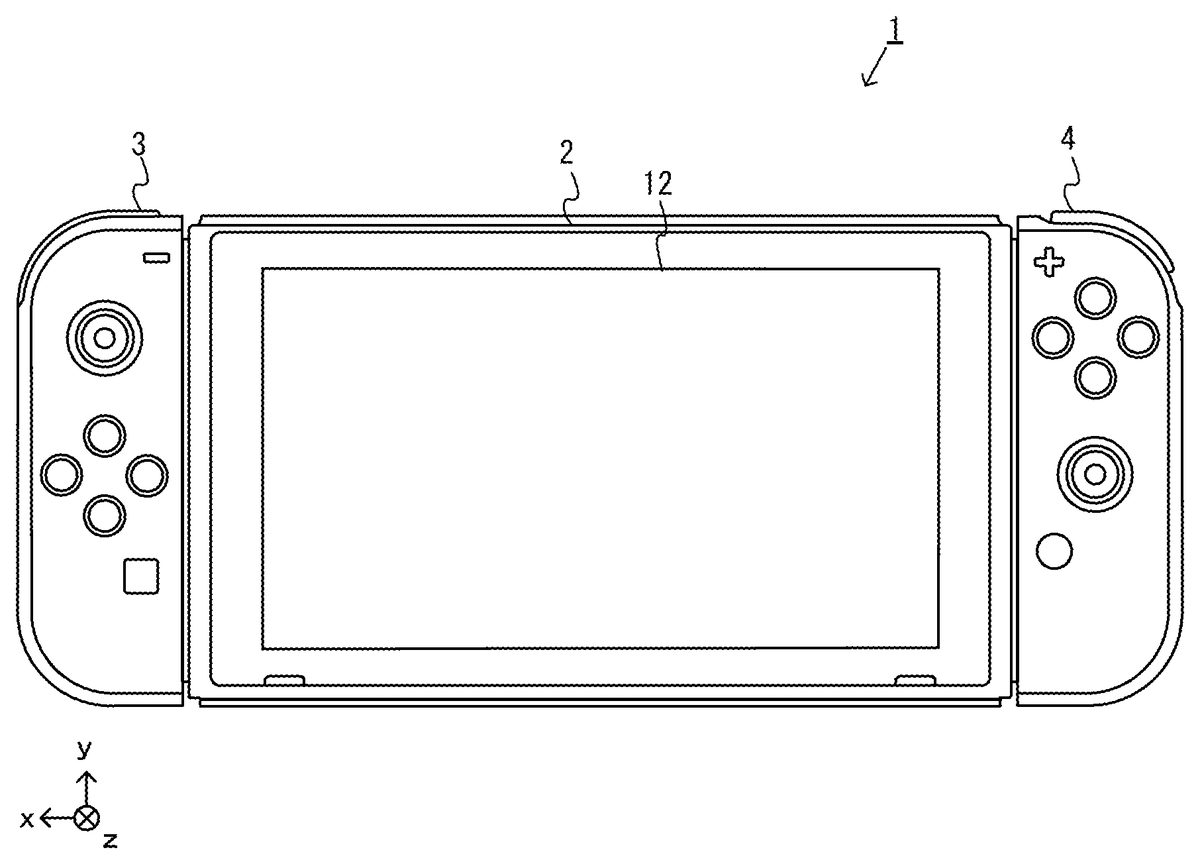
DETAILED DESCRIPTION OF NON-LIMITING EXAMPLE EMBODIMENTS 1. Structure of Information Processing System A description is given below of an information processing system, an information processing apparatus, a game program, and a game processing method according to an exemplary embodiment. In the exemplary embodiment, an information processing system1includes a main body apparatus (information processing apparatus; which functions as a game apparatus main body in the exemplary embodiment)2, a left controller3, and a right controller4. Further, in another form, the information processing system may further include a cradle5(seeFIGS. 6 and 7and the like) in addition to the above configuration. In the information processing system1according to the exemplary embodiment, the left controller3and the right controller4are attachable to and detachable from the main body apparatus2. The information processing system1can be used as a unified apparatus obtained by attaching each of the left controller3and the right controller4to the main body apparatus2. Further, the main body apparatus2, the left controller3, and the right controller4can also be used as separate bodies (seeFIG. 2). Further, the information processing system1can be used in the form in which an image is displayed on the main body apparatus2, and in the form in which an image is displayed on another display device such as a television. In the first form, the information processing system1can be used as a mobile apparatus (e.g., a mobile game apparatus). Further, in the second form, the information processing system1can be used as a stationary apparatus (e.g., a stationary game apparatus). FIG. 1is a diagram showing the state where the left controller3and the right controller4are attached to the main body apparatus2in an example of the information processing system1according to the exemplary embodiment. As shown inFIG. 1, the information processing system1includes the main body apparatus2, the left controller3, and the right controller4. Each of the left controller3and the ...
DETAILED DESCRIPTION OF NON-LIMITING EXAMPLE EMBODIMENTS
1. Structure of Information Processing System
A description is given below of an information processing system, an information processing apparatus, a game program, and a game processing method according to an exemplary embodiment. In the exemplary embodiment, an information processing system1includes a main body apparatus (information processing apparatus; which functions as a game apparatus main body in the exemplary embodiment)2, a left controller3, and a right controller4. Further, in another form, the information processing system may further include a cradle5(seeFIGS. 6 and 7and the like) in addition to the above configuration. In the information processing system1according to the exemplary embodiment, the left controller3and the right controller4are attachable to and detachable from the main body apparatus2. The information processing system1can be used as a unified apparatus obtained by attaching each of the left controller3and the right controller4to the main body apparatus2. Further, the main body apparatus2, the left controller3, and the right controller4can also be used as separate bodies (seeFIG. 2). Further, the information processing system1can be used in the form in which an image is displayed on the main body apparatus2, and in the form in which an image is displayed on another display device such as a television. In the first form, the information processing system1can be used as a mobile apparatus (e.g., a mobile game apparatus). Further, in the second form, the information processing system1can be used as a stationary apparatus (e.g., a stationary game apparatus).
FIG. 1is a diagram showing the state where the left controller3and the right controller4are attached to the main body apparatus2in an example of the information processing system1according to the exemplary embodiment. As shown inFIG. 1, the information processing system1includes the main body apparatus2, the left controller3, and the right controller4. Each of the left controller3and the right controller4is attached to and unified with the main body apparatus2. The main body apparatus2is an apparatus for performing various processes (e.g., game processing) in the information processing system1. The main body apparatus2includes a display12. Each of the left controller3and the right controller4is an apparatus including operation sections with which a user provides inputs.
FIG. 2is a diagram showing an example of the state where each of the left controller3and the right controller4is detached from the main body apparatus2. As shown inFIGS. 1 and 2, the left controller3and the right controller4are attachable to and detachable from the main body apparatus2. It should be noted that hereinafter, the left controller3and the right controller4will occasionally be referred to collectively as a “controller”. It should be noted that in the exemplary embodiment, an “operation device” operated by a single user may be a single controller (e.g., one of the left controller3and the right controller4) or a plurality of controllers (e.g., both the left controller3and the right controller4, or these controllers and another controller), and the “operation device” can be configured by one or more controllers. A description is given below of examples of the specific configurations of the main body apparatus2, the left controller3, and the right controller4.
FIG. 3is six orthogonal views showing an example of the main body apparatus2. As shown inFIG. 3, the main body apparatus2includes an approximately plate-shaped housing11. In the exemplary embodiment, a main surface (in other words, a surface on a front side, i.e., a surface on which the display12is provided) of the housing11has a generally rectangular shape. In the exemplary embodiment, the housing11has a horizontally long shape. That is, in the exemplary embodiment, the longitudinal direction of the main surface of the housing11(i.e., an x-axis direction shown inFIG. 1) is referred to as a “horizontal direction” (also as a “left-right direction”), the short direction of the main surface (i.e., a y-axis direction shown inFIG. 1) is referred to as a “vertical direction” (also as an “up-down direction”), and a direction perpendicular to the main surface (i.e., a z-axis direction shown inFIG. 1) is referred to as a depth direction (also as a “front-back direction”). The main body apparatus2can be used in the orientation in which the main body apparatus2is horizontally long. Further, the main body apparatus2can also be used in the orientation in which the main body apparatus2is vertically long. In this case, the housing11may be considered as having a vertically long shape.
It should be noted that the housing11are optional. As an example, the housing11may have a portable size. Further, the main body apparatus2alone or the unified apparatus obtained by attaching the left controller3and the right controller4to the main body apparatus2may function as a mobile apparatus. The main body apparatus2or the unified apparatus may function as a handheld apparatus or a portable apparatus.
As shown inFIG. 3, the main body apparatus2includes the display12, which is provided on the main surface of the housing11. The display12displays an image (a still image or a moving image) acquired or generated by the main body apparatus2. In the exemplary embodiment, the display12is a liquid crystal display device (LCD). The display12, however, may be a display device of any type.
Further, the main body apparatus2includes a touch panel13on a screen of the display12. In the exemplary embodiment, the touch panel13is of a type that allows a multi-touch input (e.g., a capacitive type). The touch panel13, however, may be of any type. For example, the touch panel13may be of a type that allows a single-touch input (e.g., a resistive type).
The main body apparatus2includes speakers (i.e., speakers88shown inFIG. 8) within the housing11. As shown inFIG. 3, speaker holes11aand11bare formed on the main surface of the housing11. Then, sounds output from the speakers88are output through the speaker holes11aand11b.
Further, the main body apparatus2includes a left terminal17for the main body apparatus2to perform wired communication with the left controller3, and a right terminal21for the main body apparatus2to perform wired communication with the right controller4.
As shown inFIG. 3, the main body apparatus2includes a slot23. The slot23is provided on an upper side surface of the housing11. The slot23is so shaped as to allow a predetermined type of storage medium to be attached to the slot23. The predetermined type of storage medium is, for example, a dedicated storage medium (e.g., a dedicated memory card) for the information processing system1and an information processing apparatus of the same type as the information processing system1. The predetermined type of storage medium is used to store, for example, data (e.g., saved data of an application or the like) used by the main body apparatus2and/or a program (e.g., a program for an application or the like) executed by the main body apparatus2. Further, the main body apparatus2includes a power button28and sound volume buttons26aand26b.
The main body apparatus2includes a lower terminal27. The lower terminal27is a terminal for the main body apparatus2to communicate with the cradle5, which will be described later. In the exemplary embodiment, the lower terminal27is a USB connector (more specifically, a female connector).
FIG. 4is six orthogonal views showing an example of the left controller3. As shown inFIG. 4, the left controller3includes a housing31. In the exemplary embodiment, the housing31is approximately plate-shaped. In the exemplary embodiment, the housing31has a vertically long shape, i.e., is shaped to be long in the up-down direction (i.e., the y-axis direction shown inFIG. 1). In the state where the left controller3is detached from the main body apparatus2, the left controller3can also be held in the orientation in which the left controller3is vertically long. The housing31has such a shape and a size that when held in the orientation in which the housing31is vertically long, the housing31can be held with one hand, particularly the left hand. Further, the left controller3can also be held in the orientation in which the left controller3is horizontally long. When held in the orientation in which the left controller3is horizontally long, the left controller3may be held with both hands.
The left controller3includes an analog stick32. As shown inFIG. 4, the analog stick32is provided on a main surface of the housing31. The analog stick32can be used as a direction input section with which a direction can be input. The user tilts the analog stick32and thereby can input a direction corresponding to the direction of the tilt (and input a magnitude corresponding to the angle of the tilt). It should be noted that the left controller3may include a directional pad, a slide stick that allows a slide input, or the like as the direction input section, instead of the analog stick. Further, in the exemplary embodiment, it is possible to provide an input by pressing the analog stick32.
The left controller3includes various operation buttons. First, the left controller3includes four operation buttons33to36(specifically, a right direction button33, a down direction button34, an up direction button35, and a left direction button36) on the main surface of the housing31. Further, the left controller3includes a record button37and a “−” (minus) button47. The left controller3includes a first L-button38and a ZL-button39in an upper left portion of a side surface of the housing31. Further, the left controller3includes a second L-button43and a second R-button44, on the side surface of the housing31on which the left controller3is attached to the main body apparatus2. These operation buttons are used to give instructions depending on various programs (e.g., an OS program and an application program) executed by the main body apparatus2.
Further, the left controller3includes a terminal42for the left controller3to perform wired communication with the main body apparatus2.
FIG. 5is six orthogonal views showing an example of the right controller4. As shown inFIG. 5, the right controller4includes a housing51. In the exemplary embodiment, the housing51has a vertically long shape, i.e., is shaped to be long in the up-down direction. In the state where the right controller4is detached from the main body apparatus2, the right controller4can also be held in the orientation in which the right controller4is vertically long. The housing51has such a shape and a size that when held in the orientation in which the housing51is vertically long, the housing51can be held with one hand, particularly the right hand. Further, the right controller4can also be held in the orientation in which the right controller4is horizontally long. When held in the orientation in which the right controller4is horizontally long, the right controller4may be held with both hands.
Similarly to the left controller3, the right controller4includes an analog stick52as a direction input section. In the exemplary embodiment, the analog stick52has the same configuration as that of the analog stick32of the left controller3. Further, the right controller4may include a directional pad, a slide stick that allows a slide input, or the like, instead of the analog stick. Further, similarly to the left controller3, the right controller4includes four operation buttons53to56(specifically, an A-button53, a B-button54, an X-button55, and a Y-button56) on a main surface of the housing51. Further, the right controller4includes a “+” (plus) button57and a home button58. Further, the right controller4includes a first R-button60and a ZR-button61in an upper right portion of a side surface of the housing51. Further, similarly to the left controller3, the right controller4includes a second L-button65and a second R-button66.
Further, the right controller4includes a terminal64for the right controller4to perform wired communication with the main body apparatus2.
FIG. 6is a diagram showing the overall configuration of another example of the information processing system according to the exemplary embodiment. As shown inFIG. 6, as an example, the unified apparatus obtained by attaching the left controller3and the right controller4to the main body apparatus2can be mounted on the cradle5. Further, as yet another example, only the main body apparatus2can also be mounted on the cradle5in the state where the left controller3and the right controller4are detached from the main body apparatus2. Further, the cradle5can communicate (through wired communication or wireless communication) with a stationary monitor6(e.g., a stationary television), which is an example of an external display device separate from the display12. Although the details will be described later, when the unified apparatus or the main body apparatus2alone is mounted on the cradle5, the information processing system can display on the stationary monitor6an image acquired or generated by the main body apparatus2. Further, in the exemplary embodiment, the cradle5has the function of charging the unified apparatus or the main body apparatus2alone mounted on the cradle5. Further, the cradle5has the function of a hub device (specifically, a USB hub).
FIG. 7is a diagram showing an example of the external configuration of the cradle5. The cradle5includes a housing on which the unified apparatus or the main body apparatus2alone can be detachably mounted (or attached). In the exemplary embodiment, as shown inFIG. 7, the housing includes a first supporting portion71, in which a groove71ais formed, and an approximately planar second supporting portion72.
As shown inFIG. 7, the groove71aformed in the first supporting portion71has a shape corresponding to the shape of a lower portion of the unified apparatus. Specifically, the groove71ais so shaped as to allow the lower portion of the unified apparatus to be inserted into the groove71a, and more specifically, is so shaped as to approximately coincide with the lower portion of the main body apparatus2. Thus, the lower portion of the unified apparatus is inserted into the groove71a, whereby it is possible to mount the unified apparatus on the cradle5. Further, the second supporting portion72supports a front surface of the unified apparatus (i.e., the surface on which the display12is provided) of which the lower portion is inserted into the groove71a. With the second supporting portion72, the cradle5can support the unified apparatus more stably. It should be noted that the shape of the housing shown inFIG. 7is merely illustrative. In another exemplary embodiment, the housing of the cradle5may have any shape that allows the main body apparatus2to be mounted on the housing.
As shown inFIG. 7, further, the cradle5includes a main body terminal73for the cradle5to communicate with the unified apparatus. As shown inFIG. 7, the main body terminal73is provided on a bottom surface of the groove71a, which is formed in the first supporting portion71. More specifically, the main body terminal73is provided at the position where the lower terminal27of the main body apparatus2comes into contact with the main body terminal73when the unified apparatus is attached to the cradle5. In the exemplary embodiment, the main body terminal73is a USB connector (more specifically, a male connector).
Although not shown inFIG. 7, the cradle5includes a terminal (includes a plurality of terminals, specifically, a monitor terminal132, a power supply terminal134, and extension terminals137, which are shown inFIG. 10in the exemplary embodiment) on a back surface of the housing. The details of these terminals will be described later.
FIG. 8is a block diagram showing an example of the internal configuration of the main body apparatus2. The main body apparatus2includes components81to98shown inFIG. 8in addition to the components shown inFIG. 3. Some of the components81to98may be mounted as electronic components on an electronic circuit board and accommodated in the housing11.
The main body apparatus2includes a CPU (Central Processing Unit)81. The CPU81is an information processing section for executing various types of information processing to be executed by the main body apparatus2. The CPU81executes an information processing program (e.g., a game program) stored in a storage section (specifically, an internal storage medium such as a flash memory84, an external storage medium attached to each of the slots23and24, or the like), thereby performing the various types of information processing.
The main body apparatus2includes a flash memory84and a DRAM (Dynamic Random Access Memory)85as examples of internal storage media built into the main body apparatus2. The flash memory84and the DRAM85are connected to the CPU81. The flash memory84is a memory mainly used to store various data (or programs) to be saved in the main body apparatus2. The DRAM85is a memory used to temporarily store various data used for information processing.
The main body apparatus2includes a slot interface (hereinafter abbreviated as “I/F”)91. The slot I/F91is connected to the CPU81. The slot I/F91is connected to the slot23, and in accordance with an instruction from the CPU81, reads and writes data from and to the predetermined type of storage medium (e.g., a dedicated memory card) attached to the slot23.
The CPU81appropriately reads and writes data from and to the flash memory84, the DRAM85, and each of the above storage media, thereby performing the above information processing.
The main body apparatus2includes a network communication section82. The network communication section82is connected to the CPU81. The network communication section82communicates (specifically, through wireless communication) with an external apparatus via a network. In the exemplary embodiment, as a first communication form, the network communication section82connects to a wireless LAN and communicates with an external apparatus, using a method compliant with the Wi-Fi standard. Further, as a second communication form, the network communication section82wirelessly communicates with another main body apparatus2of the same type, using a predetermined communication method (e.g., communication based on a unique protocol or infrared light communication). It should be noted that the wireless communication in the above second communication form achieves the function of enabling so-called “local communication” in which the main body apparatus2can wirelessly communicate with another main body apparatus2placed in a closed local network area, and the plurality of main body apparatuses2directly communicate with each other to transmit and receive data.
The main body apparatus2includes a controller communication section83. The controller communication section83is connected to the CPU81. The controller communication section83wirelessly communicates with the left controller3and/or the right controller4. The communication method between the main body apparatus2and the left controller3and the right controller4is optional. In the exemplary embodiment, the controller communication section83performs communication compliant with the Bluetooth (registered trademark) standard with the left controller3and with the right controller4.
The CPU81is connected to the left terminal17, the right terminal21, and the lower terminal27. When performing wired communication with the left controller3, the CPU81transmits data to the left controller3via the left terminal17and also receives operation data from the left controller3via the left terminal17. Further, when performing wired communication with the right controller4, the CPU81transmits data to the right controller4via the right terminal21and also receives operation data from the right controller4via the right terminal21. Further, when communicating with the cradle5, the CPU81transmits data to the cradle5via the lower terminal27. As described above, in the exemplary embodiment, the main body apparatus2can perform both wired communication and wireless communication with each of the left controller3and the right controller4. Further, when the unified apparatus obtained by attaching the left controller3and the right controller4to the main body apparatus2or the main body apparatus2alone is attached to the cradle5, the main body apparatus2can output data (e.g., image data or sound data) to the stationary monitor6via the cradle5.
Here, the main body apparatus2can communicate with a plurality of left controllers3simultaneously (in other words, in parallel). Further, the main body apparatus2can communicate with a plurality of right controllers4simultaneously (in other words, in parallel). Thus, the user can provide inputs to the main body apparatus2using a plurality of left controllers3and a plurality of right controllers4.
The main body apparatus2includes a touch panel controller86, which is a circuit for controlling the touch panel13. The touch panel controller86is connected between the touch panel13and the CPU81. Based on a signal from the touch panel13, the touch panel controller86generates, for example, data indicating the position where a touch input is provided. Then, the touch panel controller86outputs the data to the CPU81.
Further, the display12is connected to the CPU81. The CPU81displays a generated image (e.g., an image generated by executing the above information processing) and/or an externally acquired image on the display12.
The main body apparatus2includes a codec circuit87and speakers (specifically, a left speaker and a right speaker)88. The codec circuit87is connected to the speakers88and a sound input/output terminal25and also connected to the CPU81. The codec circuit87is a circuit for controlling the input and output of sound data to and from the speakers88and the sound input/output terminal25. That is, if receiving sound data from the CPU81, the codec circuit87outputs sound signals obtained by performing D/A conversion on the sound data to the speakers88or the sound input/output terminal25. Consequently, sounds are output from the speakers88or a sound output section (e.g., earphones) connected to the sound input/output terminal25. Further, if receiving a sound signal from the sound input/output terminal25, the codec circuit87performs A/D conversion on the sound signal and outputs sound data in a predetermined format to the CPU81. Further, the sound volume buttons26are connected to the CPU81. Based on an input to the sound volume buttons26, the CPU81controls the volume of sounds output from the speakers88or the sound output section.
The main body apparatus2includes a power control section97and a battery98. The power control section97is connected to the battery98and the CPU81. Further, although not shown inFIG. 8, the power control section97is connected to components of the main body apparatus2(specifically, components that receive power supplied from the battery98, the left terminal17, and the right terminal21). Based on a command from the CPU81, the power control section97controls the supply of power from the battery98to the above components.
Further, the battery98is connected to the lower terminal27. When an external charging device (e.g., the cradle5) is connected to the lower terminal27, and power is supplied to the main body apparatus2via the lower terminal27, the battery98is charged with the supplied power.
FIG. 9is a block diagram showing an example of the internal configuration of the information processing system1. It should be noted that the details of the internal configuration of the main body apparatus2in the information processing system1are shown inFIG. 8and therefore are omitted inFIG. 9.
The left controller3includes a communication control section101, which communicates with the main body apparatus2. As shown inFIG. 9, the communication control section101is connected to components including the terminal42. In the exemplary embodiment, the communication control section101can communicate with the main body apparatus2through both wired communication via the terminal42and wireless communication not via the terminal42. The communication control section101controls the method for communication performed by the left controller3with the main body apparatus2. That is, when the left controller3is attached to the main body apparatus2, the communication control section101communicates with the main body apparatus2via the terminal42. Further, when the left controller3is detached from the main body apparatus2, the communication control section101wirelessly communicates with the main body apparatus2(specifically, the controller communication section83). The wireless communication between the communication control section101and the controller communication section83is performed in accordance with the Bluetooth (registered trademark) standard, for example.
Further, the left controller3includes a memory102such as a flash memory. The communication control section101includes, for example, a microcomputer (or a microprocessor) and executes firmware stored in the memory102, thereby performing various processes.
The left controller3includes buttons103(specifically, the buttons33to39,43, and44). Further, the left controller3includes the analog stick (“stick” inFIG. 9)32. Each of the buttons103and the analog stick32outputs information regarding an operation performed on itself to the communication control section101repeatedly at appropriate timing.
The left controller3includes an acceleration sensor104. In the exemplary embodiment, the acceleration sensor104detects the magnitudes of linear accelerations along predetermined three axial (e.g., XYZ axes shown inFIG. 11) directions. It should be noted that the acceleration sensor104may detect an acceleration along one axial direction or accelerations along two axial directions. Further, the left controller3includes an angular velocity sensor105. In the exemplary embodiment, the angular velocity sensor105detects angular velocities about predetermined three axes (e.g., the XYZ axes shown inFIG. 11). It should be noted that the angular velocity sensor105may detect an angular velocity about one axis or angular velocities about two axes. Each of the acceleration sensor104and the angular velocity sensor105is connected to the communication control section101. Then, the detection results by the acceleration sensor104and the angular velocity sensor105are output to the communication control section101repeatedly at appropriate timing.
The communication control section101acquires information regarding an input (specifically, information regarding an operation or the detection result of the sensor) from each of input sections (specifically, the buttons103, the analog stick32, and the sensors104and105). The communication control section101transmits operation data including the acquired information (or information obtained by performing predetermined processing on the acquired information) to the main body apparatus2. It should be noted that the operation data is transmitted repeatedly, once every predetermined time. It should be noted that the interval at which the information regarding an input is transmitted from each of the input sections to the main body apparatus2may or may not be the same.
The above operation data is transmitted to the main body apparatus2, whereby the main body apparatus2can obtain inputs provided to the left controller3. That is, the main body apparatus2can determine operations on the buttons103and the analog stick32based on the operation data. Further, the main body apparatus2can calculate information regarding the motion and/or the orientation of the left controller3based on the operation data (specifically, the detection results of the acceleration sensor104and the angular velocity sensor105).
The left controller3includes a vibrator107for giving notification to the user by a vibration. In the exemplary embodiment, the vibrator107is controlled by a command from the main body apparatus2. That is, if receiving the above command from the main body apparatus2, the communication control section101drives the vibrator107in accordance with the received command. Here, the left controller3includes a codec section106. If receiving the above command, the communication control section101outputs a control signal corresponding to the command to the codec section106. The codec section106generates a driving signal for driving the vibrator107by amplifying the control signal from the communication control section101and outputs the driving signal to the vibrator107. Consequently, the vibrator107operates.
More specifically, the vibrator107is a linear vibration motor. Unlike a regular motor that rotationally moves, the linear vibration motor is driven in a predetermined direction in accordance with an input voltage and therefore can be vibrated at an amplitude and a frequency corresponding to the waveform of the input voltage. In the exemplary embodiment, a vibration control signal transmitted from the main body apparatus2to the left controller3may be a digital signal representing the frequency and the amplitude every unit of time. In another exemplary embodiment, information indicating the waveform itself may be transmitted. The transmission of only the amplitude and the frequency, however, enables a reduction in the amount of communication data. Additionally, to further reduce the amount of data, only the differences between the numerical values of the amplitude and the frequency at that time and the previous values may be transmitted, instead of the numerical values. In this case, the codec section106converts a digital signal indicating the values of the amplitude and the frequency acquired from the communication control section101into the waveform of an analog voltage and inputs a voltage in accordance with the resulting waveform, thereby driving the vibrator107. Thus, the main body apparatus2changes the amplitude and the frequency to be transmitted every unit of time and thereby can control the amplitude and the frequency at which the vibrator107is to be vibrated at that time. It should be noted that not only a single amplitude and a single frequency, but also two or more amplitudes and two or more frequencies may be transmitted from the main body apparatus2to the left controller3. In this case, the codec section106combines waveforms indicated by the plurality of received amplitudes and frequencies and thereby can generate the waveform of a voltage for controlling the vibrator107.
The left controller3includes a power supply section108. In the exemplary embodiment, the power supply section108includes a battery and a power control circuit. Although not shown inFIG. 7, the power control circuit is connected to the battery and also connected to components of the left controller3(specifically, components that receive power supplied from the battery).
As shown inFIG. 9, the right controller4includes a communication control section111, which communicates with the main body apparatus2. Further, the right controller4includes a memory112, which is connected to the communication control section111. The communication control section111is connected to components including the terminal64. The communication control section111and the memory112have functions similar to those of the communication control section101and the memory102, respectively, of the left controller3. Thus, the communication control section111can communicate with the main body apparatus2through both wired communication via the terminal64and wireless communication not via the terminal64(specifically, communication compliant with the Bluetooth (registered trademark) standard). The communication control section111controls the method for communication performed by the right controller4with the main body apparatus2.
The right controller4includes input sections similar to the input sections (specifically, buttons113, the analog stick52, an acceleration sensor114, and an angular velocity sensor115) of the left controller3. Specifically, the right controller4includes buttons113, the analog stick52, and inertial sensors (an acceleration sensor114and an angular velocity sensor115). These input sections have functions similar to those of the input sections of the left controller3and operate similarly to the input sections of the left controller3.
Further, the right controller4includes a vibrator117and a codec section116. The vibrator117and the codec section116operate similarly to the vibrator107and the codec section106, respectively, of the left controller3. That is, in accordance with a command from the main body apparatus2, the communication control section111causes the vibrator117to operate, using the codec section116.
The right controller4includes a power supply section118. The power supply section118has a function similar to that of the power supply section108of the left controller3and operates similarly to the power supply section108.
FIG. 10is a block diagram showing an example of the internal configuration of the cradle5. It should be noted that the details of the internal configuration of the main body apparatus2are shown inFIG. 8and therefore are omitted inFIG. 10.
As shown inFIG. 10, the cradle5includes a conversion section131and a monitor terminal132. The conversion section131is connected to the main body terminal73and the monitor terminal132. The conversion section131converts the formats of signals of an image (or video) and a sound received from the main body apparatus2into formats in which the image and the sound are output to the stationary monitor6. Here, in the exemplary embodiment, the main body apparatus2outputs signals of an image and a sound as display port signals (i.e., signals compliant with the DisplayPort standard) to the cradle5. Further, in the exemplary embodiment, as the communication between the cradle5and the stationary monitor6, communication based on the HDMI (registered trademark) standard is used. That is, the monitor terminal132is an HDMI terminal, and the cradle5and the stationary monitor6are connected together by an HDMI cable. Then, the conversion section131converts the display port signals (specifically, the signals representing the video and the sound) received from the main body apparatus2via the main body terminal73into HDMI signals. The converted HDMI signals are output to the stationary monitor6via the monitor terminal132.
The cradle5includes a power control section133and a power supply terminal134. The power supply terminal134is a terminal for connecting a charging device (e.g., an AC adapter or the like) (not shown). In the exemplary embodiment, an AC adapter is connected to the power supply terminal134, and mains electricity is supplied to the cradle5. When the main body apparatus2is attached to the cradle5, the power control section133supplies power from the power supply terminal134to the main body apparatus2via the main body terminal73. Consequently, the battery98of the main body apparatus2is charged.
Further, the cradle5includes a connection processing section136and extension terminals137. Each of the extension terminals137is a terminal for connecting to another apparatus. In the exemplary embodiment, the cradle5includes a plurality of (more specifically, three) USB terminals as the extension terminals137. The connection processing section136is connected to the main body terminal73and the extension terminals137. The connection processing section136has a function as a USB hub and for example, manages the communication between an apparatus connected to each of the extension terminals137and the main body apparatus2connected to the main body terminal73(i.e., transmits a signal from a certain apparatus to another apparatus by appropriately distributing the signal). As described above, in the exemplary embodiment, the information processing system1can communicate with another apparatus via the cradle5. It should be noted that the connection processing section136may be able to change the communication speed, or supply power to the apparatus connected to the extension terminal137.
As describe above, in the information processing system1according to the exemplary embodiment, the left controller3and the right controller4are attachable to and detachable from the main body apparatus2. Further, the unified apparatus obtained by attaching the left controller3and the right controller4to the main body apparatus2or the main body apparatus2alone is attached to the cradle5and thereby can output an image (and a sound) to the stationary monitor6. A description is given below using the information processing system in use forms in which an image (and a sound) is output to the stationary monitor6by attaching the main body apparatus2alone to the cradle5in the state where the left controller3and the right controller4are detached from the main body apparatus2.
As described above, in the exemplary embodiment, the information processing system1can also be used in the state where the left controller3and the right controller4are detached from the main body apparatus2(referred to as a “separate state”). As a form in a case where an operation is performed on the same application (e.g., a game application) using the information processing system1in the separate state, a form in which a single user uses both the left controller3and the right controller4is possible. It should be noted that when a plurality of users perform operations using the same application in this use form, a form is possible in which a plurality of sets of the left controller3and the right controller4are prepared, and each user uses one of the plurality of sets.
FIGS. 11 to 13are diagrams showing an example of the state where a single user uses the information processing system1by holding a set of the left controller3and the right controller4in the separate state. As shown inFIGS. 11 to 13, in the separate state, the user can view an image displayed on the stationary monitor6while operating the left controller3and the right controller4by holding the left controller3with their left hand and the right controller4with their right hand.
For example, in the exemplary embodiment, the user holds the left controller3with their left hand such that the down direction of the longitudinal direction of the left controller3(the down direction (the negative y-axis direction) shown inFIG. 1), which is vertically long and approximately plate-shaped, is the vertical direction, also the side surface (the side surface on which a slider40is provided) that is in contact with the main body apparatus2when the left controller3is attached to the main body apparatus2is directed forward, and also the main surface of the left controller3(the surface on which the analog stick32is provided) is directed to the right. Further, the user holds the right controller4with their right hand such that the down direction of the longitudinal direction of the right controller4(the up-down direction (the negative y-axis direction) shown inFIG. 1), which is vertically long and approximately plate-shaped, is the vertical direction, also the side surface (the side surface on which the slider40is provided) that is in contact with the main body apparatus2when the right controller4is attached to the main body apparatus2is directed forward, and also the main surface of the right controller4(the surface on which the analog stick52is provided) is directed to the left. In the state where the left controller3is held with the left hand, and the right controller4is held with the right hand (hereinafter, the orientations of the left controller3and the right controller4held in these directions will occasionally be referred to as “basic orientations”), each controller is moved in up, down, left, right, front, and back directions, rotated, or swung, whereby game play is performed in accordance with the motion or the orientation of the controller.
It should be noted that to facilitate the understanding of the directions of accelerations and angular velocities generated in the left controller3, a front direction in the above holding state (the direction from a round side surface to the side surface in contact with the main body apparatus2, and the negative x-axis direction shown inFIG. 1) is defined as a positive X-axis direction. A right direction in the above holding state (the direction from a back surface to the main surface, and the negative z-axis direction shown inFIG. 1) is defined as a positive Y-axis direction. An up direction in the above holding state (the direction toward the up direction of the longitudinal direction, and the positive y-axis direction shown inFIG. 1) is defined as a positive Z-axis direction. Then, the acceleration sensor104of the left controller3can detect accelerations in the XYZ-axis directions, and the angular velocity sensor105can detect angular velocities about the XYZ-axis directions. Further, to facilitate the understanding of the directions of accelerations and angular velocities generated in the right controller4, a front direction in the above holding state (the direction from a round side surface to the side surface in contact with the main body apparatus2, and the positive x-axis direction shown inFIG. 1) is defined as a positive X-axis direction. A right direction in the above holding state (the direction from the main surface to a back surface, and the positive z-axis direction shown inFIG. 1) is defined as a positive Y-axis direction. An up direction in the above holding state (the direction toward the up direction of the longitudinal direction, and the positive y-axis direction shown inFIG. 1) is defined as a positive Z-axis direction. Then, the acceleration sensor114of the right controller4can detect accelerations in the XYZ-axis directions, and the angular velocity sensor115can detect angular velocities about the XYZ-axis directions.
2. Outline of Game Operation
Next, an outline of a game operation according to the exemplary embodiment is described with reference toFIGS. 14 to 20. In the exemplary embodiment, four objects, namely, first to fourth player objects, to be operated by players (in other words, users of the information processing system) appear in a three-dimensional game space. In the exemplary embodiment, each of four users operates one of the player objects. Specifically, a first user operates the first player object, a second user operates the second player object, a third user operates the third player object, and a fourth user operates the fourth player object. Although the details will be described later, a game of the exemplary embodiment is a competition game, and the respectively player objects are separated into two groups to compete. Here, the first player object and the second player object make a first group (a friend group for the first player object), the third player object and the fourth player object make a second group (an enemy group for the first player object), and the first group and the second group compete against each other. A description is given below of the game operation in a case where the first user operates the first player object by using the left controller3and the right controller4.
FIGS. 14 to 19are diagrams showing examples of a game image displayed in a game played by moving the left controller3and the right controller4. As shown inFIG. 14, in this exemplary game, an image of a game (e.g., a boxing game) in which a first player object P1and a second player object (not shown) compete against a third player object P3and a fourth player object P4is displayed on the stationary monitor6.
The user operating the left controller3and the right controller4can operate the first player object P1by swinging the main body of the left controller3and/or the main body of the right controller4, or changing the orientations of the main body of the left controller3and/or the main body of the right controller4. For example, the user swings the left controller3and thereby can control the action of a left-fist object G1, which represents a left glove (a left first) of the first player object P1. The user swings the right controller4and thereby can control the action of a right-fist object G2, which represents a right glove (a right first) of the first player object P1. Specifically, when the user performs the operation of swinging so as to throw a left punch using the left hand holding the left controller3, the left-fist object G1, which represents the left glove of the first player object P1, moves toward the place where the third player object P3or the fourth player object P4as an enemy object is placed. Further, when the user performs the operation of swinging so as to throw a right punch using the right hand holding the right controller4, the right-fist object G2, which represents the right glove of the first player object P1, moves toward the place where the enemy object is placed (seeFIGS. 15 and 16).
For example, when the right controller4is swung so as to be pushed forward (in the positive X-axis direction of the right controller4) in the state where neither of the left controller3and the right controller4moves (the state shown inFIG. 14), then as shown inFIG. 15, the right-fist object G2of the first player object P1moves toward the enemy object in accordance with the motion of the right controller4in the state where an effect image Ie1is provided. Consequently, a game image is displayed such that the first player object P1throws a right punch at the enemy object.
Here, the moving direction of the left-fist object G1starting moving is set by the orientation of the left controller3when the left controller3is swung so as to be pushed forward. Further, the moving direction of the right-fist object G2starting moving is set by the orientation of the right controller4when the right controller4is moved so as to be pushed forward. For example, when the right controller4moves in the positive X-axis direction as shown inFIG. 15, a moving direction D1of the right-fist object G2is set in accordance with the orientation in a roll direction of the right controller4in this movement. As an example, in the exemplary embodiment, in the period in which the right controller4moves, the tilt in the Y-axis direction of the right controller4with respect to the direction in which a gravitational acceleration acts in real space is calculated, and the moving direction D1of the right-fist object G2is calculated based on the tilt in the Y-axis direction. Specifically, when the tilt in the Y-axis direction indicates that the right controller4is in the orientation in which the right controller4roll-rotates in the right direction with respect to the above reference orientation, the right-fist object G2moves in the right direction in a virtual space. Further, when the tilt in the Y-axis direction indicates that the right controller4is in the orientation in which the right controller4roll-rotates in the left direction with respect to the reference orientation, the right-fist object G2moves in the left direction in the virtual space. Then, the angle at which the moving direction shifts in the right direction or the left direction is calculated in accordance with the tilt angle in the Y-axis direction.
In this exemplary game, even when the distance between the first player object P1and the enemy object is relatively long in the virtual space, it is possible to throw a punch. The arms of the first player object P1extend, whereby the left-fist object G1and the right-fist object G2can move by a relatively long distance. Then, the left-fist object G1or the right-fist object G2collides with another object (e.g., the enemy object) or moves by a predetermined distance, then finishes the movement, and returns to a movement start position where the left-fist object G1or the right-fist object G2starts moving (e.g., a hand portion of the first player object P1shown inFIG. 14). The left-fist object G1and the right-fist object G2return to the movement start positions and thereby can make a next movement toward the enemy object. In other words, it is possible to throw a next punch. Thus, the time from when the left-fist object G1or the right-fist object G2starts moving from the movement start position to when the left-fist object G1or the right-fist object G2returns to the movement start position again is longer than in a general boxing game.
In this exemplary game, when the left-fist object G1and/or the right-fist object G2move in the virtual space, the controllers for operating the objects vibrate. For example, when the left-fist object G1moves in accordance with the fact that the left controller3is swung so as to be pushed forward, the left controller3vibrates in accordance with the fact that the left-fist object G1moves in the virtual space. Further, when the right-fist object G2moves in accordance with the fact that the right controller4is swung so as to be pushed forward, the right controller4vibrates in accordance with the fact that the right-fist object G2moves in the virtual space (the state inFIG. 15). Specifically, when the left controller3and/or the right controller4are swung so as to be pushed forward, the main body apparatus2generates outward vibration data in accordance with the types, the moving velocities, the moving directions, and the like of the left-fist object G1and/or the right-fist object G2moving in the virtual space, and transmits the outward vibration data to the left controller3and/or the right controller4. Further, when the left-fist object G1and/or the right-fist object G2collide with another object, the main body apparatus2generates vibration data indicating vibrations corresponding to the collision and transmits the vibration data to the left controller3and/or the right controller4. Further, when the left-fist object G1and/or the right-fist object G2move on homeward paths for returning to the movement start positions, the main body apparatus2generates homeward vibration data in accordance with the types, the moving velocities, the moving directions, and the like of the left-first object G1and/or the right-fist object G2moving on the homeward paths and transmits the homeward vibration data to the left controller3and/or the right controller4. Consequently, the left controller3and/or the right controller4receiving various vibration data vibrate based on the vibration data.
In this exemplary game, even while the left-fist object G1or the right-fist object G2is moving using the movement time of the left-fist object G1or the right-fist object G2(typically, the period in which the left-fist object G1or the right-fist object G2is moving in the direction of the enemy object), it is possible to change a trajectory moving in accordance with the orientation or the motion of the left controller3or the right controller4. For example, when the left controller3or the right controller4rotates in the roll direction or rotates in a yaw direction from the orientation of the left controller3or the right controller4when the left-fist object G1or the right-fist object G2starts moving, the trajectory of the left-fist object G1or the right-fist object G2is changed in accordance with the rotation. For example, in the example shown inFIG. 16, after the right controller4is swung so as to be pushed forward in the positive X-axis direction, the moving direction of the right-fist object G2changes to D2in accordance with the fact that the right controller4rotationally moves in the left roll direction (θx inFIG. 16) during the movement of the right-fist object G2. Further, when the moving direction of the right-fist object G2changes, an effect image Ie2is provided for the right-fist object G2.
As an example, in the exemplary embodiment, in the state where the rotational velocity (the angular velocity) about the X-axis of the left controller3or the right controller4after the left-fist object G1or the right-fist object G2starts moving is the rotation in the roll direction, the trajectory of the left-fist object G1or the right-fist object G2moving based on this rotational velocity about the X-axis is changed. Specifically, when the rotational velocity of the left controller3roll-rotating in the right direction about the X-axis while the left-fist object G1is moving is obtained, the trajectory of the left-fist object G1is changed in the right direction in the virtual space. When the rotational velocity of the left controller3roll-rotating in the left direction about the X-axis is obtained, the trajectory of the left-fist object G1is changed in the left direction in the virtual space. Further, when the rotational velocity of the right controller4roll-rotating in the right direction about the X-axis while the right-fist object G2is moving is obtained, the trajectory of the right-fist object G2is changed in the right direction in the virtual space. When the rotational velocity of the right controller4roll-rotating in the left direction about the X-axis is obtained, the trajectory of the right-fist object G2is changed in the left direction in the virtual space.
As another example, in the exemplary embodiment, in the state where the rotational velocity (the angular velocity) of the left controller3or the right controller4with respect to the direction of gravity in real space after the left-fist object G1or the right-fist object G2starts moving is the rotation in the yaw direction, the trajectory of the left-fist object G1or the right-fist object G2moving based on this rotational velocity about the direction of gravity is changed. Specifically, when the rotational velocity of the left controller3yaw-rotating in the right direction about the direction of gravity while the left-fist object G1is moving is obtained, the trajectory of the left-fist object G1is changed in the right direction in the virtual space. When the rotational velocity of the left controller3yaw-rotating in the left direction about the direction of gravity is obtained, the trajectory of the left-fist object G1is changed in the left direction in the virtual space. Further, when the rotational velocity of the right controller4yaw-rotating in the right direction about the direction of gravity while the right-fist object G2is moving is obtained, the trajectory of the right-fist object G2is changed in the right direction in the virtual space. When the rotational velocity of the right controller4yaw-rotating in the left direction about the direction of gravity is obtained, the trajectory of the right-fist object G2is changed in the left direction in the virtual space.
As described above, when the trajectories of the left-fist object G1and/or the right-fist object G2change, the vibrations of the left controller3and/or the right controller4also change. For example, when the outward trajectories of the left-fist object G1and/or the right-first object G2change, the main body apparatus2calculates change parameters for the amplitudes and/or the frequencies of the vibrations in accordance with changes in the motions or the orientations of the left controller3and/or the right controller4(e.g., the angular velocities in the roll direction or the yaw direction), temporarily changes the outward vibration data using the change parameters, and then changes back the outward vibration data again. Consequently, receiving the outward vibration data that temporarily changes, the left controller3and/or the right controller4change the amplitudes and/or the frequencies of the vibrations based on the outward vibration data.
Further, in this exemplary game, using the magnitude of an acceleration generated in the left controller3or the right controller4, it is determined whether or not the left controller3or the right controller4is swung. Then, when it is determined that the left controller3is swung in the positive X-axis direction in the state where the left-fist object G1is placed at the movement start position (hereinafter referred to as a “first movement-start-allowed state”), the left-fist object G1starts moving from the movement start position toward the enemy object. Further, when it is determined that the right controller4is swung in the positive X-axis direction in the state where the right-fist object G2is placed at the movement start position (hereinafter referred to as a “second movement-start-allowed state”), the right-fist object G2starts moving from the movement start position toward the enemy object. In the exemplary embodiment, however, even when the left controller3is not in the first movement-start-allowed state, but when the left controller3enters the first movement-start-allowed state within a predetermined time from when it is determined that the left controller3is swung in the positive X-axis direction, it is possible to start the movement of the left-fist object G1from the movement start position toward the enemy object in accordance with the operation of swinging the left controller3. Further, even when the right controller4is not in the second movement-start-allowed state, but when the right controller4enters the second movement-start-allowed state within a predetermined time from when it is determined that the right controller4is swung in the positive X-axis direction, it is possible to start the movement of the right-fist object G2from the movement start position toward the enemy object in accordance with the operation of swinging the right controller4. As described above, in the exemplary embodiment, even when the left controller3and/or the right controller4are not in the first movement-start-allowed state and/or the second movement-start-allowed state, the left controller3and/or the right controller4are swung, whereby it is possible to give an instruction to start the movements of the left-fist object G1and/or the right-fist object G2. Thus, it is possible to facilitate an operation even in a game where the state where an operation instruction can be given intermittently occurs. That is, as described above, in the exemplary game, the time from when the left-fist object G1or the right-first object G2starts moving from the movement start position to when the left-fist object G1or the right-fist object G2returns to the movement start position again is longer than that in a general boxing game. Thus, it is possible that the operation of swinging the left controller3or the right controller4precedes in the state where the user cannot wait until the first movement-start-allowed state or the second movement-start-allowed state. However, even when such a preceding operation is performed, it is possible to aid the preceding operation without invalidating the preceding operation and make use of the preceding operation for a game operation.
In this exemplary game, as shown inFIG. 17, the left-fist object G1and the right-first object G2are caused to simultaneously start moving from the movement start positions, whereby a predetermined action is performed. For example, when, within a predetermined period from when one of the left-fist object G1and the right-fist object G2starts moving, the other starts moving, a “both-hand punch action” is started in which the left-fist object G1and the right-fist object G2are a set. Here, in the “both-hand punch action”, the state where a collision area A is formed between the left-fist object G1and the right-fist object G2moving in the virtual space is represented as a game image, and the left-fist object G1and the right-fist object G2move toward the enemy object in the state where the collision area A is formed. Then, when the left-fist object G1or the right-fist object G2that is moving or the collision area A collides with the enemy object, a predetermined action is performed in which damage greater than that in the case where the left-fist object G1or the right-fist object G2solely collides with the enemy object is imparted to the enemy object. In the exemplary embodiment, in the “both-hand punch action”, when the left-fist object G1, the right-fist object G2, or the collision area A collides with the enemy object, the action of throwing the enemy object is performed. The “both-hand punch action” may be an action of putting the enemy object out of action. It should be noted that even during the execution of the “both-hand punch action”, the trajectories of the movements of the left-fist object G1and/or the right-fist object G2can be changed in accordance with the orientations or the motions of the left controller3and/or the right controller4. Thus, the trajectories of the movements of the left-fist object G1and/or the right-fist object G2are changed, whereby it is possible to also change the range of the collision area A. Thus, it is possible to make a more strategic attack on the enemy object.
As described above, in the exemplary embodiment, the operation display mode in the case where the actions of both the left-fist object G1and the right-fist object G2are performed (FIG. 17) is different from the operation display mode in the case where the punching action of one of the left-fist object G1and the right-fist object G2is performed (FIG. 15). That is, in the former case, an effect image Ie2is provided for the first object performing the action. In the latter case, an effect image (i.e., the collision area A) different from the effect image Ie2is provided for the first object. Thus, which action is being performed can be presented in an easy-to-understand manner to the user.
Even when the left-fist object G1and the right-fist object G2move in the state where such an action is performed, the left controller3and/or the right controller4vibrate in accordance with the movements of the objects. Specifically, when the left-fist object G1and the right-fist object G2move by the both-hand punch action, the main body apparatus2generates action outward vibration data in accordance with the types, the moving velocities, the moving directions, and the like of the left-fist object G1and the right-fist object G2moving in the virtual space and transmits the action outward vibration data to the left controller3and the right controller4. Further, when the collision area A, the left-fist object G1, or the right-fist object G2collides with another object, the main body apparatus2generates vibration data indicating a vibration corresponding to the collision and transmits the vibration data to the left controller3and the right controller4. Further, when the left-fist object G1and the right-fist object G2move on the homeward paths for returning to the movement start positions, the main body apparatus2generates homeward vibration data in accordance with the types, the moving velocities, the moving directions, and the like of the left-fist object G1and the right-fist object G2moving on the homeward paths and transmits the homeward vibration data to the left controller3and the right controller4. Consequently, even when the both-hand punch action is performed, the left controller3and the right controller4receiving various vibration data vibrate based on the vibration data.
Further, when the trajectories of the left-fist object G1and the right-fist object G2change during the execution of the both-hand punch action, the vibrations of the left controller3and the right controller4also change. For example, when the outward trajectories of the left-first object G1and the right-fist object G2change during the execution of the both-hand punch action, the main body apparatus2calculates change parameters for the amplitudes and/or the frequencies of the vibrations in accordance with the changes in the motions or the orientations of the left controller3and/or the right controller4, temporarily changes the action outward vibration data using the change parameters, and then changes back the action outward vibration data again. Consequently, receiving the action outward vibration data that temporarily changes, the left controller3and the right controller4change the amplitudes and/or the frequencies of the vibrations based on the action outward vibration data.
In this exemplary game, it is possible to move the first player object P1in the virtual space in accordance with the motions and/or the orientations of both the left controller3and the right controller4. For example, when both the left controller3and the right controller4rotate in a pitch direction or rotate in the roll direction in real space, the first player object P1is caused to move in accordance with the tilts of the rotations (e.g., θx shown inFIG. 18) (seeFIG. 18). Specifically, the tilts in the X-axis direction and the Y-axis direction of the left controller3and the tilts in the X-axis direction and the Y-axis direction of the right controller4with respect to the direction of gravity in real space are calculated. Then, based on these tilts, when it is determined that both the left controller3and the right controller4are in the orientations in which the left controller3and the right controller4are tilted forward, the first player object P1is caused to move forward in the virtual space by the amount of movement corresponding to the angles at which both the left controller3and the right controller4are tilted forward (e.g., the average value of the tilt angle of the left controller3and the tilt angle of the right controller4). In the exemplary embodiment, the first player object P1moves in a direction with respect to the front direction of the first player object P1. That is, in the above case, the first player object P1moves in the front direction of the first player object P1. In another exemplary embodiment, the first player object P1may move in a direction with respect to a direction in accordance with a line-of-sight direction of a virtual camera (i.e., a depth direction of the screen).
Further, based on these tilts, when it is determined that both the left controller3and the right controller4are in the orientations in which the left controller3and the right controller4are tilted backward, the first player object P1is caused to move backward (i.e., backward with respect to the front direction of the first player object P1) in the virtual space by the amount of movement corresponding to the angles at which both the left controller3and the right controller4are tilted backward (e.g., the average value of these angles). Further, based on these tilts, when it is determined that both the left controller3and the right controller4are in the orientations in which the left controller3and the right controller4are tilted to the left, the first player object P1is caused to move to the left (i.e., to the left with respective to the front direction of the first player object P1) in the virtual space by the amount of movement corresponding to the angles at which both the left controller3and the right controller4are tilted to the left (e.g., the average value of these angles) (seeFIG. 18). Further, based on these tilts, when it is determined that both the left controller3and the right controller4are in the orientation in which the left controller3and the right controller4are tilted to the right, the first player object P1is caused to move to the right (i.e., to the right with respective to the front direction of the first player object P1) in the virtual space by the amount of movement corresponding to the angles at which both the left controller3and the right controller4are tilted to the right (e.g., the average value of these angles).
In the exemplary game, it is possible to cause the first player object P1to perform a guard action in accordance with the motions and/or the orientations of both the left controller3and the right controller4. While performing the guard action, the first player object P1is not damaged even if a punch of another object hits the first player object P1. However, the first player object P1cannot avoid, even with the guard action, the throw action due to the both-hand punch action of another player object (that is, the first player object P1, even during the guard action, is thrown by the both-hand punch action of the other player object). In addition, while performing the guard action, the first player object P1cannot throw a punch, and cannot perform the both-hand punch action.
In the exemplary embodiment, based on the tilts described above, when it is determined that both the left controller3and the right controller4are in the orientations in which the left controller3and the right controller4are tilted inward, the first player object P1performs the guard action (FIG. 19). Specifically, the main body apparatus2calculates a tilt of the left controller3in the X-axis direction and a tilt of the right controller4in the X-axis direction with respect to the direction of gravity in the real space. Then, based on these tilts, when it is determined that both the left controller3and the right controller4are in the orientations in which the left controller3and the right controller4are tilted inward at a predetermined angle or more (e.g., θx shown inFIG. 19), the main body apparatus2causes the first player object P1to perform the guard action.
In the exemplary game, it is possible to cause the first player object P1to perform an action in accordance with an operation using the analog stick and/or the operation buttons of the controller, in addition to the operation of moving the controller. For example, the main body apparatus2causes the first player object P1to perform a jumping action in accordance with a pressing input to a predetermined operation button of the controller.
While the operation method for the first player object P1has been described above, operation methods for the second to fourth player objects are the same as the operation method for the first player object P1in the exemplary embodiment. That is, in the exemplary embodiment, each user performs an operation for the corresponding player object by using one set of controllers composed of a left controller and a right controller. In another exemplary embodiment, the operation methods for the second to fourth player objects may be different from the operation method for the first player object P1. For example, actions of some of the second to fourth player objects may be controlled based on an input (e.g., an input to the analog stick or a button) to one left controller or one right controller.
Further, the game of the exemplary embodiment may be a communication competition game. In this case, some of the second to fourth player objects (e.g., the third player object P3and the fourth player object P4as enemy objects) may be controlled by a user of another external device capable of communicating with the main body apparatus2via a network. For example, the external devices may be another main body apparatus of the same type as the main body apparatus2shown inFIG. 1, and the actions of the player objects may be controlled based on inputs to controllers communicable with the other main body apparatus. At this time, the main body apparatus2performs communication with two sets of controllers to acquire operation data from the two sets of controllers, while the other main body apparatus performs communication with other two sets of controllers to acquire operation data from the other two sets of controllers. It should be noted that, when a plurality of users use one main body apparatus, the display area of the stationary monitor6may be split into two display areas, and an image for each user (i.e., an image in which the game space is viewed in the line-of-sight direction from a player object operated by one user to a player object operated by the other user) may be displayed on each split display area.
In the exemplary embodiment, non-player characters may be used instead of some of the second to fourth player objects. That is, the main body apparatus2may use, instead of some of the second to fourth player objects, an object whose action is automatically controlled based on an algorithm determined in the game program. That is, the number of users who play the game of the exemplary embodiment is not limited to four, and may be one to three.
In the exemplary embodiment, it is also possible to play the above game using an attachment (an accessory device) for joining the left controller3and the right controller4to cause the left controller3and the right controller4to function as a single operation apparatus.
FIG. 20is a diagram showing an example of an accessory device to which the left controller3and the right controller4are attachable. As shown inFIG. 20, an extension grip210, which is an example of the accessory device, is an accessory device used by the user to perform an operation. The left controller3is attachable to the extension grip210, and the right controller4is also attachable to the extension grip210. Thus, with the extension grip210, the user can perform an operation by holding, in a unified manner, the two controllers3and4detached from the main body apparatus2.
The extension grip210has mechanisms similar to those of the main body apparatus2(specifically, the left rail member15, the right rail member19, and the like) as mechanisms for attaching the left controller3and the right controller4. Thus, similarly to the case where the left controller3and the right controller4are attached to the main body apparatus2, the left controller3and the right controller4can be attached to the extension grip210. Specifically, in the extension grip210, mechanisms for attaching the left controller3and the right controller4are provided on both left and right sides across a main body portion having a predetermined width, and rail members for attaching the left controller3and the right controller4are provided in parallel. Consequently, the left controller3and the right controller4are attached to the extension grip210such that the xyz-axis directions of the left controller3and the right controller4are parallel to each other. Then, the user holds with both hands the left controller3and the right controller4attached to the extension grip210and unified. Consequently, the user can hold in a unified manner the two controllers, namely the left controller3and the right controller4, detached from the main body apparatus2.
When the above game is played using the left controller3and the right controller4unified by such an extension grip210, an operation is performed using the operation buttons and the sticks provided in the left controller3and the right controller4. For example, when the B-button54of the right controller4is subjected to a pressing operation, the first player object P1throws a left punch, and the left-fist object G1starts moving. When the A-button53of the right controller4is subjected to a pressing operation, the first player object P1throws a right punch, and the right-fist object G2starts moving. When the analog stick32of the left controller3is subjected to a tilt operation while the left-fist object G1and/or the right-fist object G2are moving in a virtual game world, the moving directions of the left-fist object G1and/or the right-fist object G2that are moving change in accordance with the direction of the tilt operation and the tilt angle. When the analog stick32of the left controller3is subjected to a tilt operation in a case where both the left-fist object G1and the right-fist object G2are placed at the movement start positions, the first player object P1moves in the virtual game world in accordance with the direction of the tilt operation and the tilt angle. When the A-button53and the B-button54of the right controller4are subjected to pressing operations at substantially the same timing, the left-fist object G1and the right-fist object G2start to move. That is, the first player object P1performs the both-hand punch action. In another exemplary embodiment, the first player object P1may be caused to perform the both-hand punch action in accordance with a pressing operation to any one of the buttons of the controllers. Further, when the operation of pushing in the analog stick32of the left controller3is performed in a case where both the left-first object G1and the right-fist object G2are placed at the movement start positions, the first player object P1defends against an attack from the enemy object in the virtual game world. When the X-button55of the right controller4is subjected to a pressing operation, the first player object P1performs the action of jumping in the virtual game world. Then, when the Y-button56of the right controller4is subjected to a pressing operation, the first player object P1dashes (moves rapidly) in the virtual game world.
Also when game play is performed using the extension grip210, vibrations are imparted to the left controller3and/or the right controller4attached to the extension grip210in accordance with the states of the left-fist object G1and/or the right-fist object G2in the virtual game world. As an example, also when game play is performed using the extension grip210, the main body apparatus2generates outward vibration data in accordance with the type, the moving velocity, the moving direction, and the like of the left-fist object G1in accordance with the fact that the left-fist object G1moves in the virtual space, and transmits the outward vibration data to the left controller3. Further, the main body apparatus2generates outward vibration data in accordance with the type, the moving velocity, the moving direction, and the like of the right-fist object G2in accordance with the fact that the right-fist object G2moves in the virtual space, and transmits the outward vibration data to the right controller4. Further, also when game play is performed using the extension grip210, and when the left-fist object G1and/or the right-fist object G2collide with another object, the main body apparatus2generates vibration data indicating vibrations corresponding to the collision and transmits the vibration data to the left controller3and/or the right controller4. Further, also when game play is performed using the extension grip210, and when the left-fist object G1and/or the right-fist object G2move on the homeward paths for returning to the movement start positions, the main body apparatus2generates homeward vibration data in accordance with the types, the moving velocities, the moving directions, and the like of the left-fist object G1and/or the right-fist object G2moving on the homeward paths, and transmits the homeward vibration data to the left controller3and/or the right controller4. Consequently, also when game play is performed using the extension grip210, the left controller3and/or the right controller4receiving various vibration data vibrate based on the vibration data.
Further, also when game play is performed using the extension grip210, and when the trajectories of the left-fist object G1and/or the right-fist object G2change due to the fact that the analog stick32is subjected to a tilt operation, the vibrations of the left controller3and/or the right controller4also change. For example, when the outward trajectories of the left-fist object G1and/or the right-fist object G2change, the main body apparatus2calculates change parameters for the amplitudes and/or the frequencies of the vibrations in accordance with the angle of the tilt operation (an analog input value) on the analog stick32, temporarily changes the outward vibration data using the change parameters, and then changes back the outward vibration data again. Consequently, receiving the outward vibration data that temporarily changes, the left controller3and/or the right controller4change the amplitudes and/or the frequencies of the vibrations based on the outward vibration data.
It should be noted that when an operation is performed using an accessory device to which the left controller3and the right controller4are attachable, an operation using not only the analog stick32of the left controller3but also the analog stick52of the right controller4may be allowed. In this case, an operation using a pair of analog sticks is allowed. Thus, independent direction indications for changing the trajectory of the left-fist object G1using the analog stick32, and changing the trajectory of the right-fist object G2using the analog stick52may be allowed.
3. Connection Object
[3-1. Outline of Connection Object]
Next, a description is given of a connection object with reference toFIG. 14andFIGS. 21 to 26. As described above, in the exemplary embodiment, the first player object P1and the second player object P2(seeFIG. 21) make the first group, and the third player object P3and the fourth player object P4make the second group. In the exemplary embodiment, a connection object connects the player objects belonging to the same group to each other. That is, friend player objects are connected to each other by the connection object.
Specifically, as shown inFIG. 14, the third player object P3and the fourth player object P4as enemy objects are connected to each other by a second connection object C2. The first player object P1is connected to the second player object P2as a friend object (not shown inFIG. 14) by a first connection object C1. The connection object allows the user to easily recognize the player objects belonging to the same group, in other words, to easily understand which player object is a friend object and which object is an enemy object.
In the exemplary embodiment, the second player object P2as a friend object for the first player object P1may not be included in the display range as shown inFIG. 14. In the exemplary embodiment, since the first connection object C1connecting the first player object P1to the second player object P2is displayed, even when the second player object P2is not included in the display range, the user can understand the rough position of the second player object P2. For example, in the example shown inFIG. 14, the user can understand that the second player object P2is located on the left rear side of the first player object P1by recognizing the direction of the first connection object C1. Thus, the user can perform the game operation while taking care that a punch of the second player object P2as a friend object does not hit the first player object P1.
Although the details will be described later, in the exemplary embodiment, each player object is restricted in movement by the connection object connected to the player object. Specifically, the actions of the two player objects connected to each other by the connection object are controlled such that one of the player objects is not likely to move to a position distant from the other player object. That is, in the exemplary embodiment, the player objects belonging to the same group are restricted in movement by the connection object such that the player objects are located close to each other.
On the other hand, although the details will be described later, in the exemplary embodiment, a virtual camera is set so as to be directed to one of the third player object P3and the fourth player object P4(seeFIG. 14). Therefore, when the third player object P3and the fourth player object P4are located close to each other by the second connection object C2as described above, the player object other than the player object to which the virtual camera is directed is also likely to be included in the display range. For example, in the example shown inFIG. 14, the virtual camera is set to be directed to the third player object P3, and at this time, the fourth player object P4is likely to be included in the display range. Thus, in the exemplary embodiment, by setting the connection object, the player objects (here, the enemy objects) belonging to the same group are likely to be included in the single display range, thereby providing a game image that is easily viewable to the user.
(Display Mode of Connection Object)
FIG. 21is a diagram showing an example of two player objects connected to each other by a connection object. It should be noted that (a) ofFIG. 21shows a case where the distance between the two player objects is relatively short (i.e., a case where distance d=d1), and (b) ofFIG. 21shows a case where the distance between the two player objects is relatively long (i.e., a case where distance d=d2(>d1)). As shown inFIG. 21, in the exemplary embodiment, the first connection object C1is an object having a rope-like appearance. Although a description is given below using the first connection object C1as an example, the main body apparatus2executes, also for the second connection object C2, the same processing as that for the first connection object C1.
In the exemplary embodiment, the display mode of the first connection object C1is changed in accordance with the distance between the two player objects connected to each other by the first connection object C1(in other words, the length of the first connection object C1). Specifically, when distance d=d1, the thickness of the first connection object C1is set to a first thickness ((a) ofFIG. 21). When distance d=d2, the thickness of the first connection object C1is set to a second thickness smaller than the first thickness ((b) ofFIG. 21). In the exemplary embodiment, the main body apparatus2sets the thickness of the first connection object C1so as to be proportional to the above distance. Thus, in the exemplary embodiment, since the display mode of the connection object is changed in accordance with the above distance, the user is allowed to understand the distance by the connection object. For example, in the example shown inFIG. 14, the user is allowed to understand, by the first connection object C1, not only the direction of the second player object P2with respect to the first player object P1but also how far the second player object P2is distant from the first player object P1.
It should be noted that the main body apparatus2may change any display mode of the first connection object C1in accordance with the above distance. For example, the color of the first connection object C1may be changed in accordance with the above distance, or the interval of dots in a dotted line representing the first connection object C1may be changed in accordance with the distance. Alternatively, when the first connection object C1has a helical shape (e.g., spring-like shape), the pitch of the helix (in other words, assuming that a helix extends along a side surface of a cylinder, the length in the axial direction of the cylinder when the helix makes one round of the cylinder) may be changed in accordance with the distance.
In another exemplary embodiment, the connection object may have any shape representing that two player objects are connected to each other.FIG. 22shows another example of the connection object. As shown inFIG. 22, a connection object C11may have a shape representing a region including the first player object P1and the second player object P2. It should be noted that, as shown in (a) and (b) ofFIG. 22, a width W of a portion, of the connection object C11, between the two player objects may be changed in accordance with the distance d described above.
(Relationship Between Connection Object and Other Objects)
In the exemplary embodiment, the main body apparatus2does not execute a collision detection process for the connection object. That is, the main body apparatus2determines the state of the first connection object C1(specifically, the position and/or the direction) based on the first player object P1and the second player object P2, regardless of whether or not the first connection object C1comes into contact with another object in the game space. It should be noted that the above “another object” is, for example, a player object, or a topography object or an obstacle object arranged in the game space. In the exemplary embodiment, for example, even when an obstacle is present between the first player object P1and the second player object P2, the first connection object C1is arranged between the first player object P1and the second player object P2regardless of the presence of the obstacle. It should be noted that the display method in the case where the connection object comes into contact with another object is optional. For example, in the above case, the first connection object C1may be displayed so as to pass through (in other words, penetrate through) the obstacle.
As described above, in the exemplary embodiment, since the collision detection process is not executed for the connection object, it is possible to reduce the risk that the action of the player object is unnecessarily restricted by the connection object. For example, it is possible to prevent the movement of the player object from being restricted due to contact of the connection object with an obstacle. When the connection object comes into contact with another object, a calculation process regarding the connection object (specifically, a process of calculating the position, the direction, and/or the later-described tension of the connection object) may be complicated. In this regard, in the exemplary embodiment, the main body apparatus2need not execute the calculation process regarding the contact of the connection object with another object, it is possible to reduce the processing load in the game processing. In another exemplary embodiment, the main body apparatus2may perform collision detection between the connection object and another object.
(Setting of Virtual Camera)
In the exemplary embodiment, a virtual camera used for generating a game image is set so as to be directed to one of two enemy objects (i.e., the third player object P3and the fourth player object P4) from the first player object P1side. More specifically, the virtual camera is set such that one of the two enemy objects and the first player object P1are included in the display range (seeFIG. 14). In the following description, a player object, of the two enemy objects, which is used as a reference for setting the virtual camera is referred to as a “noticed object”. In the exemplary embodiment, as shown inFIG. 14, the third player object P3as a noticed object is arranged substantially in the center of the display range with respect to the left-right direction. Therefore, when the first user performs an operation to cause the first player object P1to throw a punch to the front, the first player object P1can throw a punch toward the noticed object, and thus the punch is easily applied to the noticed object.
In the exemplary embodiment, the noticed object is switched in accordance with a switching operation (e.g., an operation of pressing a predetermined button of the controller) performed by the first user. That is, when the switching operation is performed in the state where the noticed object is the third player object P3, the main body apparatus2changes the noticed object to the fourth player object P4. When the switching operation is performed in the state where the noticed object is the fourth player object P4, the main body apparatus2changes the noticed object to the third player object P3. Thus, the user can easily change the target enemy object.
In the exemplary embodiment, when a predetermined automatic switching condition is satisfied, the main body apparatus2automatically switches the noticed object even if the switching operation is not performed. Specifically, when the noticed object falls down, switching of the noticed object is performed. In the exemplary embodiment, the noticed object falls down after being flown by a punch of another player object or thrown by the both-hand punch action of another player object. In the exemplary embodiment, a punch applied to a fallen-down player object is invalid (i.e., no damage is applied), and therefore, it is less necessary to regard the fallen-down player as a target.
In another exemplary embodiment, the virtual camera may be set such that the first connection object C1is included in the field-of-view range. That is, the first connection object C1may be set as the noticed object described above. In still another exemplary embodiment, the first player object P1may not be included in the field-of-view range, and a so-called first-person viewpoint game image may be generated. In yet another exemplary embodiment, the main body apparatus2may allow the user to freely operate the line-of-sight direction of the virtual camera. Even in the embodiment in which the user can freely operate the line-of-sight direction of the virtual camera, since the player objects belonging to the same group are arranged close to each other by the connection object, these player objects are likely to be included in the single display range. Therefore, also in the above embodiments, it is possible to provide a game image that is easily viewable to the user as in the exemplary embodiment.
[3-2. Tension Caused by Connection Object]
In the exemplary embodiment, the main body apparatus2imposes restriction on movement of a player object connected to a connection object, by using the connection object. In the exemplary embodiment, the main body apparatus2calculates a virtual tension that acts between the player object and the connection object. By controlling the action of the player object while considering the tension, the main body apparatus2imposes restriction on movement of the player object. That is, since the player object receives a force that pulls the player object toward the connection object (depending on a situation), it is possible to make the distance between two player objects connected to each other by the connection object not likely to increase. Hereinafter, a specific example of a tension calculation method will be described with reference toFIG. 23.
FIG. 23is a diagram showing an example of a tension that acts on a player object. InFIG. 23, a description is given for a tension that acts on the first player object P1as an example, tensions that act on the respective player objects can be calculated by the same method.
In the exemplary embodiment, first, the main body apparatus2calculates a tension T1(hereinafter referred to as “uncorrected tension”) that acts in the direction of the first connection object C1. The uncorrected tension T1is parallel to the direction of the first connection object C1, and is directed from the first player object P1to the second player object P2(seeFIG. 23).
The magnitude of the uncorrected tension T1is calculated based on a length L of the first connection object C1(in other words, the distance between the first player object P1and the second player object P2). Specifically, the uncorrected tension T1is calculated in accordance with the following formula (1):
in a case where the lengthLis smaller than a reference valueL1:T1=0, and
in a case where the lengthLis equal to or greater than the reference valueL1:T1=k×(L−L1) (1)
In the above formula (1), coefficient k is a predetermined constant. As shown in formula (1), in the exemplary embodiment, when the length L of the first connection object C1is smaller than the reference value L1, the uncorrected tension T1is 0 (i.e., the tension T1is not generated). Accordingly, when the distance between the first player object P1and the second player object P2is smaller than the reference value L1, no restriction is imposed on the movement of each player object, whereby operability of the operation to each player object can be improved. When the length L of the first connection object C1is equal to or greater than the reference value L1, the uncorrected tension T1has a magnitude according to the length L. Thus, in the exemplary embodiment, the tension is calculated such that the first connection object C1is regarded as having an elastic-body-like property.
If restriction is imposed on movement of the player object by using the uncorrected tension T1as it is, there is a risk that the restriction may become excessively great in the vertical direction in the game space (specifically, a direction perpendicular to the ground. In other words, a direction parallel to the direction of gravity set in the game space). For example, in a case where the player object performs a jumping action, and if the player object cannot perform a sufficiently high jump due to the tension, the user may have an uncomfortable feeling to the jumping action. Further, in the game according to the exemplary embodiment, it is conceivable that the player object eludes a punch of an enemy object by the jumping action. Therefore, if the player object cannot perform a sufficiently high jump, the operability of the operation to the player object may be degraded.
Therefore, in the exemplary embodiment, the main body apparatus2performs correction so as to decrease a component in the vertical direction from the uncorrected tension T1. Specifically, as shown inFIG. 23, the main body apparatus2decreases a vertical-direction component T1yof the uncorrected tension T1to obtain a corrected vertical-direction component T2y. The corrected vertical-direction component T2yis obtained by, for example, multiplying the uncorrected vertical-direction component T1yby a predetermined coefficient a (0<a1.0) and is constant at the amplitude change rate MAX1at the rotational velocity Va or more. A change pattern2is a change pattern of the amplitude in which for a change in the rotational velocity V from 0 to Va, the amplitude change rate is linearly transformed from 1.0 to MAX2(MAX1>MAX2>1.0) and is constant at the amplitude change rate MAX2at the rotational velocity Va or more. A change pattern3is a change pattern of the amplitude which the amplitude change rate is transformed based on a table in which the amplitude change rate is gradually heightened from 1.0 to MAX3(MAX3>1.0) in each certain range of the rotational velocity V from 0 to Va, and is constant at the amplitude change rate MAX3at the rotational velocity Va or more.
When an amplitude change rate of 1.0 is calculated using the above change patterns, the amplitude of the outward vibration waveform is not changed, that is, the outward vibration data created in the above step S45is set as it is as the left controller vibration data Do. Further, as is clear from the above, the rotational velocity V is calculated in accordance with the angular velocity of the left controller3about the direction of the gravitational acceleration (the angular velocity in the yaw direction) or the angular velocity about the X-axis direction of the left controller3(the angular velocity in the roll direction) and is a parameter based on a change in the motion or the orientation of the left controller3. That is, when there is no change in the motion or the orientation of the left controller3in the yaw direction or the roll direction, the rotational velocity V is also 0. Thus, the amplitude change rate is also 1.0. That is, even when the amplitude of the outward vibration waveform changes by the generation of the rotational velocity V due to a change in the motion or the orientation of the left controller3, the change in the motion or the orientation stops, whereby the amplitude change rate becomes 1.0, and the outward vibration waveform returns to the previous outward vibration waveform. Thus, a change in the outward vibration data in the above step S62is used to temporarily change the outward vibration waveform generated in the above step S45. The change in the motion or the orientation of the left controller3stops, whereby the outward vibration data returns to the previous outward vibration waveform.
In the above step S62, the outward vibration data may be changed using various change patterns based on the rotational velocity V, and a change pattern to be selected may be set in accordance with the type of the left-fist object G1. Further, inFIG. 35, examples of the amplitude change rate for changing the amplitude so as to correspond to the rotational velocity V are exemplified. Alternatively, the frequency of the vibration may be changed using the same change pattern, or the frequency of the vibration may be changed using a change pattern different from that of the amplitude.
Further, in the above step S62, the outward vibration data is changed based on the rotational velocity V. Alternatively, the outward vibration data may be changed based on another parameter. For example, the outward vibration data may be changed based on the amount of change in the curve value C, or the outward vibration data may be changed based on the value of the curve value C itself. In the first case, it is possible to change the outward vibration data based on the amount of change in the curve value C subjected to the processes of the above steps S58to S61, i.e., the amount of change in the curve value C limited to the minimum value Cmin and the maximum value Cmax.
As described above, in the exemplary embodiment, when it is determined that the punch operation is being performed (i.e., when the determination result in step S42is positive), the CPU81calculates the curve value C based on the tilt of the left controller3(step S44). When it is determined that the punch operation ends (i.e., when the determination result in step S42is negative), the CPU81calculates the curve value C based on the rotational velocity of the left controller3(step S57). Here, in the above two cases, a method for calculating the curve value C is optional. For example, in another exemplary embodiment, when it is determined that the punch operation is being performed, the curve value C may be calculated based on the rotational velocity of the left controller3. When it is determined that the punch operation ends, the curve value C may be calculated based on the tilt of the left controller3.
Referring back toFIG. 31, in step S46, the CPU81calculates the moving direction of the left-fist object G1using the curve value C of the left-fist object G1, and the processing proceeds to the next step. For example, the CPU81acquires the curve value C of the left-fist object G1with reference to the curve value data Df and acquires the moving direction of the left-first object G1with reference to the player object data Dm. Then, when the acquired curve value C of the left-fist object G1is a positive value, the CPU81changes the acquired moving direction of the left-fist object G1to the right in accordance with the magnitude of the curve value and updates the player object data Dm using the changed moving direction of the left-fist object G1. Further, when the acquired curve value C of the left-fist object G1is a negative value, the CPU81changes the acquired moving direction of the left-fist object G1to the left in accordance with the magnitude of the curve value and updates the player object data Dm using the changed moving direction of the left-fist object G1.
It should be noted that when the left-fist object G1moves on the homeward path in the virtual space for returning to the movement start position, then without changing the moving direction based on the curve value C of the left-fist object G1, the moving direction may be fixedly set to the direction in which the left-fist object G1returns from the current position of the left-fist object G1to the movement start position. The determination of whether or not the left-fist object G1moves on the homeward path can be made based on whether or not the return flag described later is set to on.
Next, based on the moving direction of the left-fist object G1, the CPU81causes the left-fist object G1to move (step S47), and the processing proceeds to the next step. For example, the CPU81acquires the position and the moving direction of the left-fist object G1with reference to the player object data Dm, causes the left-fist object G1to move from the position of the left-fist object G1based on the moving direction, and updates the player object data Dm using the position of the moved left-fist object G1.
It should be noted that the moving velocity (the amount of movement) at which the left-fist object G1is caused to move in the above step S47may be such that, as an example, the moving velocity of the left-fist object G1is set in accordance with a velocity corresponding to the type of the left-fist object G1. As another example, the moving velocity of the left-fist object G1may be set in accordance with the magnitude of the acceleration when it is determined that the left controller3is swung so as to throw a punch. In this case, an initial velocity at which the left-fist object G1starts moving may be set based on the magnitude of the XZ-acceleration when the swing flag is set to on, and the moving velocity after that may be appropriately changed based on the situation of the virtual space, a change in the moving direction, a predetermined algorithm, movement characteristics set for the left-fist object G1, or the like.
Next, the CPU81determines, with reference to the action flag data Dj, whether or not the action flag is set to on (step S48). Then, when the action flag is set to on, the processing proceeds to step S49. On the other hand, when the action flag is set to off, the processing proceeds to step S70(seeFIG. 33).
In step S49, the CPU81sets the collision area A between the left-fist object G1and the right-fist object G2, and the processing proceeds to step S70(seeFIG. 33). For example, the CPU81acquires the position of the left-fist object G1and the position of the right-first object G2with reference to the player object data Dm and sets the position in the virtual space, the shape, and the range of the collision area A based on these positions, thereby updating the collision area data Dn. When the moving direction of the left-fist object G1(and the moving direction of the right-fist object G2) and the position after the movement are set in the state where the action flag is thus set to on, the collision area A is set between the left-fist object G1and the right-fist object G2.
InFIG. 33, the CPU81performs a collision detection process (step S70), and the processing proceeds to the next step. For example, with reference to the respective player object data and the collision area data Dn, the CPU81determines collision in the virtual space between the left-fist object G1and the collision area A, and another object (e.g., the enemy object) in the virtual space.
Next, the CPU81determines whether or not at least one of the left-fist object G1and the collision area A collides with another object in the virtual space (step S71). Then, when at least one of the left-fist object G1and the collision area A collides with another object, the processing proceeds to step S72. On the other hand, when neither of the left-fist object G1and the collision area A collides with another object, the processing proceeds to step S75.
In step S72, the CPU81performs a collision action process on another object, and the processing proceeds to the next step. For example, when the left-fist object G1collides with the enemy object, the CPU81imparts damage corresponding to the collision to the enemy object and also sets a predetermined action corresponding to the damage (i.e., the action of being flown described above). Further, when the collision area A collides with the enemy object, the CPU81imparts damage corresponding to the collision to the enemy object and also sets the “both-hand punch action” in which the left-fist object G1and the right-fist object G2are a set.
It should be noted that in the exemplary embodiment, not only in the period in which the left-fist object G1moves toward the enemy object, but also in the period in which the left-fist object G1returns toward the first player object P1, and when the left-fist object G1collides with another object, the collision action process is performed. However, when the collision action process is performed on another object only in the period in which the left-fist object G1moves toward the enemy object, then in the period in which the left-fist object G1returns toward the first player object P1(the state where the return flag is on), it may be always determined in the above step S71that the left-fist object G1does not collide with another object, and the collision action process may not be performed.
Next, the CPU81adds a collision vibration (step S73), and the processing proceeds to the next step. For example, the CPU81generates a collision vibration waveform corresponding to the situation where the left-fist object G1collides with another object. Then, the CPU81combines the collision vibration waveform with the vibration waveform indicated by the left controller vibration data Do to generate a new vibration waveform and updates the left controller vibration data Do using the new vibration waveform.
Next, the CPU81sets the action flag to off, thereby updating the action flag data Dj. The CPU81also sets the collision area data Dn to the state where there is no collision area (e.g., Null) (step S74), and the processing proceeds to step S75. As described above, when the action of any one of the left-fist object G1, the right-fist object G2, and the collision area A colliding with another object is set, the action flag is set to off, and also setting data regarding the collision area is erased.
In step S75, the CPU81determines, with reference to the return flag data Dk, whether or not the return flag set for the processing of the left-fist object G1is set to on. Then, when the return flag set for the processing of the left-fist object G1is set to off, the processing proceeds to step S76. On the other hand, when the return flag set for the processing of the left-first object G1is set to on, the processing proceeds to step S80.
In step S76, the CPU81determines whether or not the left-fist object G1performs the action of moving on the homeward path in the virtual space for returning to the movement start position. For example, the condition that the left-fist object G1reaches a position a predetermined distance away from the movement start position, or the condition that a predetermined time elapses after the left-fist object G1passes through the position of the enemy object, or the condition that a predetermined time elapses after the left-fist object G1or the collision area A collides with another object, or the like is satisfied, it is determined that the left-first object G1performs the action of moving on the homeward path. Then, when the left-fist object G1performs the action of moving on the homeward path, the processing proceeds to step S77. On the other hand, when the left-fist object G1does not perform the action of moving on the homeward path, the processing proceeds to step S84.
In step S77, the CPU81sets the return flag set for the processing of the left-fist object G1to on, thereby updating the return flag data Dk. Then, the processing proceeds to the next step. As described above, when the action of the left-fist object G1moving on the homeward path is set, the return flag set for the processing of the left-fist object G1is set to on.
Next, the CPU81sets a direction toward the movement start position as the moving direction of the left-fist object G1(step S78), and the processing proceeds to the next step. For example, the CPU81calculates a direction from the current position of the left-fist object G1to the movement start position as the moving direction of the left-fist object G1with reference to the player object data Dm, and updates the player object data Dm using this moving direction. It should be noted that the moving direction of the left-fist object G1set in the above step S78may be set to a direction along an object joined to the left-fist object G1(e.g., an extended arm object of the first player object P1), or may be set to return on the trajectory when the left-fist object G1moves from the movement start position.
Next, the CPU81creates homeward vibration data for vibrating the left controller3(step S79), and the processing proceeds to step S84. For example, in accordance with the type of the left-fist object G1, the CPU81generates a homeward vibration waveform when the left-fist object G1moves on the homeward path, and based on the homeward vibration waveform, the CPU81generates homeward vibration data for vibrating the left controller3, thereby updating the left controller vibration data Do. It should be noted that the CPU81may adjust the homeward vibration waveform in accordance with the moving velocity or the moving direction of the left-fist object G1, or may generate the homeward movement waveform regardless of the moving velocity or the moving direction. Further, the CPU81may add a vibration corresponding to the situation of the virtual space except for the left-fist object G1to the vibration waveform. For example, the CPU81may add to the homeward vibration waveform a vibration corresponding to the action of the first player object P1or an impact imparted to the first player object P1, a vibration corresponding to the situation of the game field, a vibration corresponding to BGM or a sound effect, or the like. Further, when the CPU81does not impart a vibration to the left controller3when the left-fist object G1moves on the homeward path, the CPU81may set, in the left controller vibration data Do, vibration data indicating an amplitude of 0 or vibration data indicating that the left controller3is not to be vibrated.
On the other hand, when the return flag is set to on, the CPU81determines whether or not the left-fist object G1returns to the movement start position (step S80). For example, with reference to the player object data Dm, when the position of the left-fist object G1is set to the movement start position, the determination is affirmative in the above step S80. Then, when the left-fist object G1returns to the movement start position, the processing proceeds to step S81. On the other hand, when the left-fist object G1does not return to the movement start position, the processing proceeds to step S84.
In step S81, the CPU81sets the movement-start-allowed flag set for the processing of the left-fist object G1to on, thereby updating the movement-start-allowed flag data Dl. Then, the processing proceeds to the next step. As described above, when the left-fist object G1enters the state where the left-fist object G1can move in the virtual space again, the current state is the first movement-start-allowed state. Thus, the movement-start-allowed flag of the left-fist object G1is set to on. It should be noted that in the above step S81, when the left-fist object G1returns to the movement start position, the movement-start-allowed flag of the left-fist object G1is immediately set to on, and the current state is the first movement-start-allowed state. Alternatively, the first movement-start-allowed state may be started at another timing. For example, the first movement-start-allowed state may be started at the timing when a predetermined time (e.g., eight frames) elapses after the left-fist object G1returns to the movement start position.
Next, the CPU81sets the movement flag and the return flag set for the processing of the left-fist object G1to off, sets the action flag to off, and sets data regarding the collision area and the moving direction of the left-fist object G1to the default values (step S82), and the processing proceeds to the next step. For example, the CPU81sets the movement flag and the return flag set for the processing of the left-fist object G1to off, thereby updating the movement flag data Di and the return flag data Dk, respectively. Further, the CPU81sets the action flag to off, thereby updating the action flag data Dj. Further, the CPU81sets setting data regarding the collision area to the state where there is no collision area (e.g., Null), thereby updating the collision area data Dn. Further, the CPU81sets the moving direction of the left-fist object G1to the default value (e.g., the front direction), thereby updating the player object data Dm.
Next, the CPU81performs the process of stopping the vibration of the left controller3(step S83), and the processing proceeds to step S84. For example, in accordance with the type of the left-fist object G1, the CPU81generates a vibration to occur when the left-first object G1returns to the movement start position, and a vibration waveform for stopping the vibration after the vibration, and based on the vibration waveform, the CPU81generates vibration data for vibrating the left controller3, thereby updating the left controller vibration data Do. It should be noted that when a vibration corresponding to the situation of the virtual space except for the movement of the left-fist object G1is to be imparted even after the movement of the left-fist object G1stops, the CPU81may add this vibration (a vibration corresponding to the action of the first player object P1or an impact imparted to the first player object P1, a vibration corresponding to the situation of the game field, a vibration corresponding to BGM or a sound effect, or the like), thereby continuously vibrating the left controller3.
In step S84, the CPU81determines whether or not the first player object P1is thrown by another player object. Although the details will be described later (step S117), in this game processing, a series of processes in steps S2to S9are also executed for each of other player objects. Therefore, when a collision area A of another player object comes into contact with the first player object P1, the CPU81determines that the first player object P1is thrown by the other player object. When the determination result in step S84is positive, the process of step S85is executed. On the other hand, when the determination result in step S84is negative, the CPU81ends the processing of this subroutine.
In step S85, the CPU81sets stop of the punch action (here, an action to move the left-fist object G1) that is being performed by the first player object P1. Thus, in the exemplary embodiment, when the first player object P1is thrown by the other player object while performing the punch action, the punch action is canceled even if the punch action is being performed. When stop of the punch action is set in step S85, the CPU81, in step S113or S114described later, causes the first player object P1to perform an action of returning the left-fist object G1to the original position (in other words, the position before start of movement). After step S85, the CPU81ends the processing of this subroutine.
In another exemplary embodiment, also in a case where a player object receives a punch of another player object (e.g., an enemy object) while performing a punch action, the punch action of the player object may be canceled, as in the case of steps S84and S85. That is, in step S84, the CPU81may determine whether or not the first player object P1is thrown/punched by another player object.
A punch action performed by a player object may be prohibited in a case where a condition regarding execution of the punch action is satisfied. For example, a parameter indicating an endurance value may be set on a first object, and the CPU81may decrease the endurance value in accordance with the fact that the first object hits another object. At this time, the CPU81may prohibit the punch action by the player object for a predetermined time period (i.e., may prevents the player object from performing the punch action even when the player performs a punch operation) on the condition that the endurance value becomes 0. Thereby, strategic characteristics of the game can be enhanced, thereby enhancing the interest of the game.
Referring back toFIG. 28, after the first object trajectory change process in the above step S6, the CPU81performs a second object trajectory change process (step S7), and the processing proceeds to the next step. It should be noted that the object trajectory change process described with reference toFIGS. 31 to 33is a subroutine used also in the second object trajectory change process in the above step S7. That is, the left controller3and the left-fist object G1as processing targets in the first object trajectory change process are switched to the right controller4and the right-fist object G2, whereby it is possible to perform similar processing using the same subroutine. Thus, the details of the second object trajectory change process in the above step S7are not described here.
Next, the CPU81performs a player object movement process (step S8), and the processing proceeds to the next step. With reference toFIG. 34, a description is given of the player object movement process performed in the above step S8.
InFIG. 34, the CPU81determines whether or not the tilts of the left controller3and the right controller4relative to the pitch direction in real space are the same direction (step S91). For example, with reference to the orientation data Db, when both the positive X-axis direction of the left controller3and the positive X-axis direction of the right controller4are an elevation direction or a depression direction with respect to the horizontal direction in real space, the determination is affirmative in the above step S91. Then, when the tilts of the left controller3and the right controller4relative to the pitch direction in real space are the same direction, the processing proceeds to step S92. On the other hand, when the tilts of the left controller3and the right controller4relative to the pitch direction in real space are not the same direction, the processing proceeds to step S93.
In step S92, the CPU81calculates an average value P of the tilt angles of the left controller3and the right controller4relative to the pitch direction in real space, and the processing proceeds to step S94. For example, with reference to the orientation data Db, the CPU81calculates the angle between the positive X-axis direction of the left controller3and the horizontal direction in real space, and the angle between the positive X-axis direction of the right controller4and the horizontal direction in real space and calculates the average value P of these angles. For example, each angle is calculated such that when the positive X-axis direction is a depression direction, the angle has a positive value, and when the positive X-axis direction is an elevation direction, the angle has a negative value.
On the other hand, when it is determined in the above step91that the tilts of the left controller3and the right controller4relative to the pitch direction in real space are not the same direction, the CPU81sets the average value P to 0 (step S93), and the processing proceeds to step S94.
In step S94, the CPU81determines whether or not the tilts of the left controller3and the right controller4relative to the roll direction in real space are the same direction. For example, with reference to the orientation data Db, when both the positive Y-axis direction of the left controller3and the positive Y-axis direction of the right controller4are an elevation direction or a depression direction with respect to the horizontal direction in real space, the determination is affirmative in the above step S94. Then, when the tilts of the left controller3and the right controller4relative to the roll direction in real space are the same direction, the processing proceeds to step S95. On the other hand, when the tilts of the left controller3and the right controller4relative to the roll direction in real space are not the same direction, the processing proceeds to step S96.
In step S95, the CPU81calculates an average value R of the tilt angles of the left controller3and the right controller4relative to the roll direction in real space, and the processing proceeds to step S97. For example, with reference to the orientation data Db, the CPU81calculates the angle between the positive Y-axis direction of the left controller3and the horizontal direction in real space, and the angle between the positive Y-axis direction of the right controller4and the horizontal direction in real space and calculates the average value R of these angles. For example, each angle is calculated such that when the positive Y-axis direction is a depression direction, the angle has a positive value, and when the positive Y-axis direction is an elevation direction, the angle has a negative value.
On the other hand, when it is determined in the above step94that the tilts of the left controller3and the right controller4relative to the roll direction in real space are not the same direction, the CPU81sets the average value R to 0 (step S96), and the processing proceeds to step S97.
In step S97, the CPU81calculates an amount of movement M by combining the amount of front-back movement corresponding to the average value P with the amount of left-right movement corresponding to the average value R, and the processing proceeds to the next step. For example, when the average value P is a positive value, the CPU81calculates, in accordance with the value of the average value P, the amount of front-back movement for moving forward in the virtual space. When the average value P is a negative value, the CPU81calculates, in accordance with the value of the average value P, the amount of front-back movement for moving backward in the virtual space. Further, when the average value R is a positive value, the CPU81calculates, in accordance with the value of the average value R, the amount of left-right movement for moving to the right in the virtual space. When the average value R is a negative value, the CPU81calculates, in accordance with the value of the average value R, the amount of left-right movement for moving to the left in the virtual space. Then, the CPU81calculates the amount of movement M relative to the virtual space by combining the amount of front-back movement with the amount of left-right movement.
Next, the CPU81scales the amount of movement M in accordance with the setting states of the movement flags (step S98), and the processing of this subroutine ends. For example, with reference to the movement flag data Di, when the movement flags set for the processing of the left-fist object G1and the right-fist object G2are both set to off, the CPU81sets the value of the amount of movement M as it is. Further, when only one of the movement flags set for the processing of the left-fist object G1and the right-fist object G2is set to on, the CPU81reduces the amount of movement M by a predetermined magnification (e.g., reduces the amount of movement M by 0.9 times). Further, when the movement flags set for the processing of the left-fist object G1and the right-fist object G2are both set to on, the CPU81sets the amount of movement M to 0. In step S113described later, the action of the first player object P1is controlled based on the amount of movement M set in the process of step S98.
Referring back toFIG. 28, after the player object movement process in step S8, the CPU81performs an action control process (step S9). The action control process is a process for controlling the actions of the respective player objects P1to P4. Hereinafter, the action control process will be described with reference toFIGS. 36 and 37.
In step S101shown inFIG. 36, the CPU81sets a connection object. That is, the CPU81calculates the position, the direction, and the length of the first connection object C1. The first connection object C1is set in accordance with the method described in the above “[3-1. Outline of connection object]. Specifically, the first connection object C1is set based on the positions of the first player object P1and the second player object P2, which are indicated by the player object data stored in the DRAM85. As described above, regarding the connection object, hitting with another object is not detected. Therefore, the CPU81sets the connection object based on only the player objects connected to each other by the connection object, regardless of whether the connection object comes into contact with another object. The CPU81stores, in the DRAM85, the player object data Dm including data indicating the position, the direction, and the length of the calculated first connection object C1. It should be noted that the position, the direction, and the length of the second connection object C2are calculated based on the positions of the third player object P3and the fourth player object P4, which are indicated by the player object data, in a similar manner to that for the first connection object C1. Subsequent to step S101, a process in step S102is executed.
In step S102, the CPU81determines the display mode of the connection object. That is, the CPU81determines the thickness of the connection object, based on the length of the connection object calculated in step S101, in accordance with the method described in the above “(Display mode of connection object)”. Subsequent to step S102, a process in step S103is executed.
In step S103, the CPU81calculates a tension to be applied to the first player object P1by the first connection object C1. This tension is calculated in accordance with the method described in the above “[3-2. Tension caused by connection object]”. Specifically, the CPU81calculates the direction and the magnitude of the tension, based on the direction and the length of the first connection object C1which are indicated by the connection object data Dq stored in the DRAM85. Further, the CPU81updates the tension data included in the player object data Dm so as to indicate the calculated tension. Subsequent to step S103, a process in step S104is executed.
In step S104, the CPU81determines whether or not the cancellation condition described above is satisfied. The determination in step S104is performed in accordance with the method described in the above “[3-3. Cancellation of restriction of connection object]”. It should be noted that whether or not the action of being flown or the action of being thrown is performed can be determined based on the result of a process in step S117described later (specifically, the process of step S117finally executed). Whether or not the throwing action is performed can be determined based on the result of the process in step S72. When the determination result in step S104is positive, a process in step S105is executed. On the other hand, when the determination result in step S104is negative, the process in step S105is skipped and a process in step S106is executed.
In step S105, the CPU81performs setting so as to cause the first player object P1to start the tension invalid action. It should be noted that, in the exemplary embodiment, the player object data includes action data indicating the content of the action being performed by the player object (including the tension invalid action). After performing setting so as to cause the first player object P1to perform the action, the CPU81updates the player object data Dm so as to include action data regarding the action. Further, in step S105, the CPU81sets the tension invalid flag to on. That is, the CPU81updates the tension invalid flag data Dr to the content indicating “ON”. Subsequent to step S105, a process in step S106is executed.
In step S106, the CPU81determines whether or not the condition for correcting the action direction of the first player object P1is satisfied. That is, the CPU81determines whether or not the correction condition is satisfied, in accordance with the method described in the above “(Correction of action direction)”. Information indicating the action contents and the action directions of the first and second player objects P1and P2, which is used for the determination process in step S106, can be acquired with reference to the player object data. When the determination result in step S106is positive, a process in step S107is executed. On the other hand, when the determination result in step S106is negative, the process in step S107is skipped and a process in step S108is executed.
In step S107, the CPU81corrects the action direction of the first player object P1. That is, the CPU81corrects the action direction in accordance with the method described in the above “(Correction of action direction)”, and updates the player object data Dm so as to indicate the corrected action direction. Subsequent to step S107, the process in step S108is executed.
In step S108, the CPU81determines whether or not the chain-action condition described above is satisfied. The determination in step S108is performed in accordance with the method described in the above “(Chain action caused by connection object)”. Information indicating the content of the action being performed by the second player object P2and information indicating the length of the first connection object C1, which are used for the determination process in step S108, can be acquired with reference to the player object data and the connection object data Dq, respectively. When the determination result in step S108is positive, a process in step S109is executed. On the other hand, when the determination result in step S108is negative, the process in step S109is skipped and a process in step S110shown inFIG. 37is executed.
In step S109, the CPU81performs setting so as to cause the first player object P1to start the chain action (specifically, the action of being thrown). That is, the CPU81updates the player object data Dm so as to include action data indicating the action of being thrown. Also in step S109, as in step S105, the CPU81sets the tension invalid flag to on. Subsequent to step S109, a process in step S110shown inFIG. 37is executed.
In step S110shown inFIG. 37, the CPU81determines whether or not a guard operation for causing the first player object P1to perform the guard operation is performed. Specifically, the CPU81, with reference to the orientation data Db, determines whether or not both the left controller3and the right controller4are tilted inward at a predetermined angle or more. When the determination result in step S110is positive, a process in step S111is executed. On the other hand, when the determination result in step S110is negative, the process in step S111is skipped and a process in step S112is executed.
In step S111, the CPU81performs setting so as to cause the first player object P1to perform the guard action. That is, the CPU81updates the player object data Dm so as to include action data indicating the guard action. Subsequent to step S111, the process in step S112is executed.
In step S112, the CPU81determines whether or not the first player object P1is being performing the tension invalid action. The determination in step S112is performed by, with reference to the tension invalid flag data, determining whether or not the tension invalid flag is set to on. When the determination result in step S112is negative, a process in step S113is executed. On the other hand, when the determination result in step S112is positive, a process in step S114is executed.
In step S113, the CPU81controls the action of the first player object P1, with restriction being imposed by the tension of the first connection object C1. In step S113, the CPU81, based on the processing results in steps S4to S8, causes the first player object P1to perform the punch action and the moving action, or the CPU81, based on the user operation for causing the first player object P1to perform a predetermined action (e.g., the jumping action or the guard action), causes the first player object P1to perform the predetermined action. Specifically, the CPU81determines the appearance state (specifically, the position, the direction, and the posture) of the first player object P1in the current frame. At this time, the CPU81determines the appearance state while considering the tension. It should be noted that the CPU81updates the player object data Dm so as to indicate the determined appearance state of the first player object P1. Subsequent to step S113, a process in step S115is executed.
In step S114, the CPU81controls the action of the first player object P1without considering the tension. In step S114, the CPU81causes the first player object P1to perform the tension invalid action described above, and determines the appearance state of the first player object P1in the current frame. At this time, the CPU81determines the appearance state without considering the tension (in other words, with the tension being ignored). The CPU81updates the player object data Dm so as to indicate the determined appearance state of the first player object P1. Subsequent to step S114, the process in step S115is executed.
In step S115, the CPU81determines whether or not the tension invalid action is finished. That is, the CPU81determines that the tension invalid action is finished when, as the result of the action control in step S114, the first player object P1falls down on the ground or the throwing action of the first player object P1is finished. When the determination result in step S115is positive, a process in step S116is executed. On the other hand, when the determination result in step S115is negative, the process in step S116is skipped and a process in step S117is executed.
In step S116, the CPU81sets the tension invalid flag to off. That is, the CPU81updates the tension invalid flag data Dr to the content indicating “OFF”. Subsequent to step S116, the process in step S117is executed.
In step S117, the CPU81performs an action control regarding the other player objects. Specifically, the CPU81executes, for each of the second to fourth player objects P2to P4, the processes (specifically, a series of processes in steps S2to S8, and a series of processes in steps S103to S116) for controlling the action thereof. After step S117, the CPU81ends the action control process shown inFIGS. 36 and 37.
Referring back toFIG. 28, after the action control process in step S9, the CPU81performs a display control process (step S10). The display control process is a process of generating a game image representing a game space, and displaying the game image on a display device (stationary monitor6). Hereinafter, the display control process will be described with reference toFIG. 38.
In step S121shown inFIG. 38, the CPU81determines whether or not a condition for switching the noticed object is satisfied. That is, when a switching operation is performed by the user or the automatic switching condition is satisfied, the CPU81determines that the condition for switching the noticed object is satisfied. On the other hand, when a switching operation is not performed by the user and the automatic switching condition is not satisfied, the CPU81determines that the condition for switching the noticed object is not satisfied. When the determination result in step S121is positive, a process in step S122is executed. On the other hand, when the determination result in step S121is negative, the process in step S122is skipped and a process in step S123is executed.
In step S122, the CPU81switches the noticed object. That is, the CPU81updates the noticed object data Ds so as to indicate the noticed object after the switching. Subsequent to step S122, the process in step S123is executed.
In step S123, the CPU81sets a virtual camera. Specifically, the CPU81sets the position, the direction, and the angle-of-view of the virtual camera, based on the player object data and the noticed object data Ds. In step S123, the direction of the virtual camera is set such that the virtual camera is directed in a direction from the first player object P1side to the noticed object side. It should be noted that the virtual camera need not be exactly directed in the direction from the first player object P1to the noticed object. The position and the angle-of-view of the virtual camera are set such that the first player object P1and the noticed object are included in the field-of-view range of the virtual camera. Subsequent to step S123, a process in step S124is executed.
In step S124, the CPU81generates a game image based on the virtual camera set through the process in step S123. For example, the CPU81arranges the respective player objects (including the left-fist object and the right-fist object) on the game field by using the player object data. Further, when the action flag indicating the action flag data Dj is set to on and the setting data regarding the collision area A is set in the collision area data Dn, the CPU81arranges an object corresponding to the collision area A between the left-fist object G1and the right-fist object G2. The CPU81generates a game image indicating the game space in which the various objects are arranged as described above, as seen from the virtual camera. It should be noted that, at this time, the CPU81performs, for a connection object, rendering in accordance with the display mode determined in step S102. Subsequent to step S124, a process in step S125is executed.
In step S125, the CPU81causes a display device (here, the stationary monitor6) to display the game image generated by the process in step S124. After step S125, the CPU81ends the display control process. A processing loop of steps S2to S12shown inFIG. 28is repeatedly executed such that the process in step S125is executed once every predetermined time period (i.e., one frame time).
Referring back toFIG. 28, after the display control process in step D10, the CPU81executes a vibration data transmitting process (step S11). Specifically, the CPU81performs the process of, in each cycle of transmitting vibration data, transmitting vibration data corresponding to this cycle to the left controller3and the right controller4, and the processing proceeds to the next step. For example, with reference to the left controller vibration data Do, the CPU81transmits vibration data for a vibration length corresponding to the transmission cycle to the left controller3. Further, with reference to the right controller vibration data Do, the CPU81transmits vibration data for a vibration length corresponding to the transmission cycle to the right controller4. The vibration data for vibrating the two controllers is thus transmitted to the left controller3and the right controller4, whereby the left controller3and the right controller4receiving the vibration data vibrate based on vibration waveforms corresponding to the vibration data.
Next, the CPU81determines whether or not the game is to be ended (step S12). In the above step S12, examples of a condition for ending the game include: the fact that the result of the above game is settled; and the fact that the user performs the operation of ending the game. If the game is not to be ended, the processing returns to the above step S2, and the process of step S2is repeated. If the game is to be ended, the processing of the flow chart ends. Hereinafter, the series of processes in steps S2to S12are repeatedly executed until it is determined in step S12that the game is to be ended.
5. Function and Effect of Exemplary Embodiment, and Modifications
According to the exemplary embodiment described above, the game program causes a computer (specifically, the CPU81of the main body apparatus2) included in an information processing apparatus for performing game processing in which a first group including a first object and a second object operated by a user competes with a second group including a third object and a fourth object, to function as means as follows:object arrangement means configured to arrange, in a virtual three-dimensional space, the first object, the second object, the third object, the fourth object, a first connection object connecting the first object and the second object, and a second connection object connecting the third object and the fourth object (steps S1, S124);action control means configured to control actions of the first object and the second object, with restriction being imposed on movements of the first object and the second object based on the first connection object, and control actions of the third object and the fourth object, with restriction being imposed on movements of the third object and the fourth object based on the second connection object (steps S113, S117);virtual camera control means configured to control a virtual camera arranged in the virtual three-dimensional space such that at least one of the third object and the fourth object is included in a field-of-view range (step S123);virtual space image generation means configured to generate a virtual space image acquired based on the virtual camera (step S124); anddisplay control means configured to cause a display device to display the virtual space image (step S125).
As described above, in the exemplary embodiment, each player object is restricted in movement by a connection object. Here, since the exemplary embodiment provides a game in which a player object competes with an enemy object by performing a punch action, namely, an action of stretching a hand to move a first object, the player object performs the action at a certain distance from the enemy object. Therefore, even when the movement of the player object is restricted by the connection object, the game balance is not considerably degraded, and the restriction of movement is sufficiently acceptable by the user.
In the exemplary embodiment, the game in which the moving object operated by the user is the first object of the player object, is described as an example. However, the type of the moving object may be optional. The moving object may be an object the moving direction of which can be operated by the user while the object is moving, as in the exemplary embodiment, or may be an object the moving direction of which cannot be operated by the user after the movement is started. Further, the moving object may be an object that returns to the position of the player object as in the exemplary embodiment, or may be an object that does not return to the position of the player object but continues to move forward, or may be an object that disappears (e.g., is exploded) when coming into contact with another object.
In the exemplary embodiment, the case where the number of player objects included in one group is two, is described as an example. However, the number of player objects included in one group may be any number as long as it is not less than 2. For example, in another exemplary embodiment, three player objects may be included in one group. At this time, the main body apparatus2may use three connection objects similar to the connection object of the exemplary embodiment, and each connection object may connect any two of the three player objects included in the group. Alternatively, the connection object may be an object representing an area enclosing the three player objects. The area may have a spherical shape, or a shape as shown inFIG. 22.
According to the exemplary embodiments described above, the game program is defined as follows. The game program defined as follows can provide a novel game.
(1-1) A game program executed by a computer of an information processing apparatus, the game program causing the computer to function as:
first movement start means configured to start a process of moving a first portion of a player object arranged in a virtual space, the first portion being different from a main portion of the player object, in a direction away from the main portion, in accordance with a first operation of a user of the information processing apparatus;
second movement start means configured to start a process of moving a second portion of the player object, the second portion being different from the main portion and the first portion, in the direction away from the main portion, in accordance with a second operation of the user;
third movement start means configured to start a process of moving the first portion and the second portion together, in the direction away from the main portion, in accordance with a third operation of the user;
first movement change means configured to change the moving direction of the first portion in accordance with a fourth operation of the user performed after the movement of the first portion is started;
second movement change means configured to change the moving direction of the second portion in accordance with a fifth operation of the user performed after the movement of the second portion is started;
third movement change means configured to change the moving direction of the first portion and the second portion in accordance with a sixth operation of the user performed after the process of moving the first portion and the second portion together is started;
first return means configured to execute a process of moving the first portion so as to be gradually returned to the main portion, in a case where a first return condition is satisfied after the movement of the first portion is started in accordance with the first operation;
second return means configured to execute a process of moving the second portion so as to be gradually returned to the main portion, in a case where a second return condition is satisfied after the movement of the second portion is started in accordance with the second operation; and
third return means configured to execute a process of moving the first portion and the second portion so as to be gradually returned to the main portion, in a case where a third return condition is satisfied after the movement of the first portion and the second portion is started in accordance with the third operation.
In the above description, “moving the first portion and the second portion together” means that the first portion and the second portion are moved in substantially the same direction at substantially the same speed, and the first portion and the second portion are not necessarily moved in a contact state.
(1-2) The game program according to the above (1-1), the game program further causing the computer to function as:
first processing means configured to, when one of the first portion and the second portion moving independently from each other collides with a target object, execute a first process for the target object; and
second processing means configured to, when the first portion and the second portion moving together collide with the target object, execute a second process, different from the first process, for the target object.
(1-3) The game program according to the above (1-2), wherein
when the state of the target object is changed from a first state to a second state, and if one of the first portion and the second portion collides with the target object, the first processing means makes the first process invalid, and
even when the state of the target object is changed from the first state to the second state, if the first portion and the second portion collide with the target object, the second processing means executes the second process.
(1-4) The game program according to the above (1-1) or (1-2), the game program further causing the computer to function as state change means configured to execute a process of changing the state of the player object in accordance with a seventh operation of the user.
(1-5) The game program according to any one of the above (1-1) to (1-4), the game program further causing the computer to function as movement control means configured to move the player object in the virtual space in accordance with an eighth operation of the user.
(1-6) The game program according to any one of the above (1-1) to (1-5), the game program further causing the computer to function as display control means configured to, when the process of moving the first portion and the second portion together is started by the third movement start means, causes an effect image regarding the first portion and the second portion to be displayed.
(1-7) The game program according to any one of the above (1-1) to (1-6), wherein the third operation is an operation in which the first operation and the second operation are performed at substantially the same timing.
(1-8) The game program according to any one of the above (1-1) to (1-7), the game program further causing the computer to function as type determination means configured to determine, based on a selection instruction of the user, the type of the first portion to be set on the player object; and
the first movement change means controls the movement of the first portion, with a movement control method being changed in accordance with the type of the first portion.
(1-9) The game program according to the above (1-8), the game program further causing the computer to function as determination means configured to, when the first portion that is moving collides with a third portion, of the target object, different from a main portion of the target object, determine whether or not the movement of the first portion should be stopped, based on the type of the first portion and the type of the third portion which are determined by the type determination means.
(2-1) A non-transitory computer-readable storage medium having, stored thereon, an information processing program executable by a computer included in an information processing apparatus configured to execute an information process based on an operation made by use of an operation device, the information processing program causing the computer to execute:
starting moving an object in a first movement direction in a virtual space based on first operation data including data representing position movement of the operation device; and
controlling the object to move in a direction curved from the first movement direction based on second operation data including data representing a rotation or an attitude of the operation device after the position movement of the operation device.
(2-2) The non-transitory computer-readable storage medium according to the above (2-1), wherein controlling the object to move in the direction curved from the first movement direction includes controlling, based on the second operation data, the object to move so as to be curved, from the first movement direction, in a direction of the rotation of the operation device, the rotation being performed after the position movement of the operation device.
(2-3) The non-transitory computer-readable storage medium according to the above (2-1) or (2-2), wherein controlling the object to move in the direction curved from the first movement direction includes controlling the movement direction of the object by use of data representing a rotation around a gravitational direction in a real space, as the data representing the rotation of the operation device.
(2-4) The non-transitory computer-readable storage medium according to the above (2-1) or (2-2), wherein controlling the object to move in the direction curved from the first movement direction includes controlling the movement direction of the object by use of data representing a rotation of the operation device around a direction of the position movement of the operation device in a real space, as the data representing the rotation of the operation device.
(2-5) The non-transitory computer-readable storage medium according to the above (2-1) to (2-4), wherein controlling the object to move in the direction curved from the first movement direction includes controlling the movement direction of the object by use of data representing an inclination with respect to a gravitational direction in a real space, as the data representing the attitude of the operation device.
(2-6) The non-transitory computer-readable storage medium according to the above (2-1) to (2-5), wherein:
the first operation data is based on a detection result provided by an acceleration sensor included in the operation device; and
the second operation data is based on a detection result provided by a gyrosensor or an acceleration sensor included in the operation device.
(2-7) The non-transitory computer-readable storage medium according to the above (2-1) to (2-5), wherein:
the first operation data is generated in accordance with a swinging operation of swinging the operation device; and
the second operation data is generated in accordance with a curving operation by which curving with respect to the swinging operation is realized.
(2-8) The non-transitory computer-readable storage medium according to the above (2-1) to (2-5), wherein:
the first operation data includes data representing the rotation or the attitude of the operation device; and
starting moving the object includes determining the first movement direction based on the data representing the rotation or the attitude of the operation device included in the first operation data.
(2-9) The non-transitory computer-readable storage medium according to the above (2-8), wherein:
the data representing the rotation of the operation device included in the first operation data is data representing an angular velocity generated in the operation device; and
starting moving the object includes:in the case where a magnitude of a component of the angular velocity around a gravitational direction in a real space is larger than a magnitude obtained as a result of subtracting the component around the gravitational direction from the angular velocity, determining the first movement direction by use of the component of the angular velocity around the gravitational direction; andin the case where the magnitude of the component of the angular velocity around the gravitational direction in the real space is smaller than, or equal to, the magnitude obtained as a result of subtracting the component around the gravitational direction from the angular velocity, determining the first movement direction by use of a component of the angular velocity around the direction of the position movement of the operation device in the real space.
(2-10) The non-transitory computer-readable storage medium according to the above (2-9), wherein starting moving the object includes, in the case where the first movement direction is determined by use of the component of the angular velocity around the direction of the position movement, determining the first movement direction while a value of degree, by which the first movement direction of the object is curved with respect to a magnitude of the data representing the rotation of the operation device, is made different in accordance with whether the component of the angular velocity around the direction of the position movement is of a positive value or a negative value.
(2-11) The non-transitory computer-readable storage medium according to the above (2-1) to (2-10), wherein:
the first movement direction is a front-rear direction as seen from a virtual camera generating a virtual image including the object; and
controlling the object to move in the direction curved from the first movement direction includes controlling, based on the second operation data, the movement direction of the object to be curved from the first movement direction in an upward direction, a downward direction, a leftward direction or a rightward direction as seen from the virtual camera.
(2-12) The non-transitory computer-readable storage medium according to the above (2-1) to (2-11), wherein controlling the object to move in the direction curved from the first movement direction includes, in the case where the object moves in a direction of returning to a movement start position in the virtual space, not changing the movement direction of the object based on the second operation data based on the second operation data.
(2-13) The non-transitory computer-readable storage medium according to the above (2-1) to (2-12), wherein the object is a first of a player character in the virtual space.
(2-14) The non-transitory computer-readable storage medium according to the above (2-1) to (2-13), wherein:
the information processing apparatus is configured to execute an information process based on an operation made by use of two of the operation devices;
starting moving the object includes executing a process of starting moving each of two of the objects based on an operation made on each of the two operation devices, and controlling the object to move in the direction curved from the first movement direction includes executing a process of curving the movement direction of each of the two objects based on an operation made on each of the two operation devices.
(2-15) The non-transitory computer-readable storage medium according to the above (2-14), wherein the information processing program causes the computer to execute moving a player character including the object to move in the virtual space based on an operation made on each of the two operation devices.
In the exemplary embodiment described above, in addition to the game program described in the above (1-1) to (1-8) and (2-1) to (2-15), an information processing apparatus and an information processing system each including the respective means described in the above (1-1) to (1-8) and (2-1) to (2-15) are disclosed. Further, in the exemplary embodiment described above, a game processing method executed in the information processing apparatus according to the above (1-1) to (1-8) and (2-1) to (2-15) is disclosed.
In the exemplary embodiment described above, to vibrate the left controller3and the right controller4, when the temporary variable S is equal to or greater than 7, outward vibration data is generated in step S195, and when the temporary variable S is less than 7, the outward vibration data is changed based on the rotational velocity V in step S222. Here, the temporary variable S is the following variable. When it is determined that the left controller3or the right controller4is swung so as to throw a punch, the temporary variable S is set to a predetermined number (step S22), and then, 1 is subtracted from the temporary variable S in accordance with the progress of the processing. That is, immediately after it is determined based on the accelerations that the left controller3and the right controller4are swung so as to throw a punch, the left controller3and the right controller4vibrate based on outward vibration data, and after that, vibrate based on vibration data changing based on the rotational velocity V. Thus, in the exemplary embodiment, it is possible to variedly vibrate the left controller3and/or the right controller4and also enable realistic game play. Further, vibration data for vibrating the left controller3and the right controller4can be changed in accordance with the motions and the orientations of the left controller3and/or the right controller4and can also be changed in accordance with an analog output by a tilt operation or the like on an analog stick. Thus, it is possible to perform flexible control corresponding to an operation form.
It should be noted that in the above exemplary embodiment, an example has been used where, when an acceleration generated in a controller satisfies a predetermined condition, predetermined outward vibration data is generated, and when an angular velocity generated in the controller in the period in which the outward vibration data is output satisfies a predetermined condition, vibration data for temporarily changing the amplitude and/or the frequency of a vibration is generated and output. Alternatively, vibration data may be generated in another form. For example, a parameter for determining whether or not the operation of throwing a punch using a controller may not be an acceleration generated in the controller, and may be determined using an angular velocity generated in the controller or both an acceleration and an angular velocity generated in the controller. Further, a condition for determining whether or not vibration data is to be temporarily changed may not be a condition based on an angular velocity generated in the controller, and may be a condition based on an acceleration generated in the controller or a condition based on both an acceleration and an angular velocity generated in the controller. Further, the above determination may be made based on an operation on an operation button or a direction indication section provided in the controller.
Further, a temporary change in vibration data corresponding to the rotational velocity V may occur multiple times. For example, as is apparent from the above flow charts, when the rotational velocity V is generated multiple times during the outward movement of the left-fist object G1or the right-fist object G2, outward vibration data temporarily changes every time the rotational velocity V is generated. If the processing of the above flow charts is performed, it is possible to temporarily change outward vibration data multiple times.
Further, in the above exemplary embodiment, an example has been used where, when a change in the motion or the orientation of a controller satisfies a predetermined condition in the period in which predetermined outward vibration data is output, vibration data for temporarily changing the amplitude and/or the frequency of a vibration is output. Alternatively, a vibration parameter for making a temporarily change may be set in another form. As a first example, in accordance with the fact that a change in the motion or the orientation of a controller satisfies a predetermined condition when the controller intermittently vibrates in a predetermined cycle, vibration data may be output in which the period in which the cycle or the vibration is interrupted and/or the time in which the vibration is applied change. As a second example, when a change in the motion or the orientation of a controller satisfies a predetermined condition in the period in which predetermined outward vibration data is output, a single vibration having an amplitude greater than that of a vibration waveform based on the outward vibration data may be added a predetermined number of times, thereby outputting vibration data to be temporarily changed. As a third example, in a case where an object to which predetermined outward vibration data is output is a particular type of object, and even when a change in the motion or the orientation of a controller satisfies a predetermined condition, a vibration may not be changed, and the outward vibration data may continue to be output.
Further, in the above exemplary embodiment, an example has been used where outward vibration data is generated with the movement of the left-fist object G1or the right-fist object G2that starts moving in accordance with the motion of the left controller3or the right controller4. Alternatively, the left-fist object G1or the right-fist object G2may start moving in accordance with another operation. For example, in accordance with a user operation on a predetermined operation section (e.g., an operation button or a direction indication section) provided in the left controller3or the right controller4, the left-fist object G1or the right-fist object G2may start moving, and outward vibration data may be generated with the movement of the left-fist object G1or the right-fist object G2.
Further, in the above exemplary embodiment, even during the movements of the left-fist object G1and the right-fist object G2, the trajectories of the left-fist object G1and the right-fist object G2change due to an operation using the left controller3or the right controller4. Thus, as a result, the above processing is based on the premise that the time from when the first movement-start-allowed state ends to when the current state enters a next first movement-start-allowed state, and the time from when the second movement-start-allowed state ends to when the current state enters a next second movement-start-allowed state are long. As described above, in a game where the time until a next movement can be started is long, game specifications are effective in which the operation of causing an object to start moving (a swing operation) is received in a preceding manner. However, it goes without saying that a game may be used where the time until a next movement can be started is long based on other specifications. For example, in the above exemplary game, the arm of the first player object P1extends, whereby it is possible to control a motion during the movement of the first player object P1. Alternatively, the exemplary embodiment may be applied to a game where another part (e.g., the leg) of the body of the player object extends, or a game where an object (a whip object, a pleated object, or the like) owned by the player object extends. Yet alternatively, the exemplary embodiment may be applied to a game where an object (e.g., a radio-controlled object, a robot, a rocket punch, or the like) that can be remotely operated by the player object is operated during the movement of the player object, and when the object returns to a hand portion of the player object again, a next movement can be made. Yet alternatively, the exemplary embodiment may be applied to a game where an object (a bird, a boomerang, a bowling ball, or the like) once shot returns.
Further, the above “both-hand punch action” has been described using an example where the left-fist object G1and the right-fist object G2as a set perform a predetermined action. Alternatively, the left-fist object G1and the right-fist object G2as a set may simply move. In this case, as the movement form of the left-fist object G1and the right-fist object G2represented as a game image, the left-fist object G1and the right-fist object G2as a set simply move. Alternatively, when at least one of the left-fist object G1and the right-fist object G2collides with the enemy object, damage greater than that in the case where the left-fist object G1or the right-fist object G2solely collides with the enemy object may be imparted to the enemy object.
Further, in the above exemplary embodiment, an example has been used where in accordance with an operation using the left controller3or the right controller4, the positions of the left-fist object G1and the right-fist object G2in the left-right direction in the virtual space are controlled, and a vibration temporarily changes in accordance with this operation. Alternatively, the positions of the left-fist object G1and the right-fist object G2in the up-down direction in the virtual space and/or the positions of the left-fist object G1and the right-fist object G2in the front-back direction may be configured to be controlled. In this case, the positions of the left-fist object G1and/or the right-fist object G2in the up-down direction in the virtual space may be configured to be controlled in accordance with the motions of the left controller3and/or the right controller4in the up-down direction in real space and/or the orientations of the left controller3and/or the right controller4in the pitch direction, and a vibration may temporarily change in accordance with this operation. Yet alternatively, the positions of the left-fist object G1and/or the right-fist object G2in the front-back direction in the virtual space may be configured to be controlled in accordance with the motions of the left controller3and/or the right controller4in the front-back/rear direction in real space and/or the orientations of the left controller3and/or the right controller4in the pitch direction, and a vibration may temporarily change in accordance with this operation. Yet alternatively, the orientations of the left-fist object G1and the right-fist object G2in the virtual space may be configured to be controlled in accordance with an operation using the left controller3or the right controller4. In this case, the orientations of the left-fist object G1and/or the right-fist object G2relative to the roll direction in the virtual space may be configured to be controlled in accordance with the orientations of the left controller3and/or the right controller4in the roll direction in real space, and a vibration may temporarily change in accordance with this operation. Yet alternatively, the orientations of the left-fist object G1and/or the right-fist object G2relative to the pitch direction in the virtual space may be configured to be controlled in accordance with the orientations of the left controller3and/or the right controller4in the pitch direction in real space, and a vibration may temporarily change in accordance with this operation. Yet alternatively, the orientations of the left-fist object G1and/or the right-fist object G2relative to the yaw direction in the virtual space may be configured to be controlled in accordance with the orientations of the left controller3and/or the right controller4in the yaw direction in the real space, and a vibration may temporarily change in accordance with this operation.
Further, in the above exemplary embodiment, the method for detecting the motions and the orientations of the left controller3and the right controller4is merely illustrative, and the motions and the orientations of the left controller3and the right controller4may be detected using another method or other data. For example, the acceleration sensors104and114and the angular velocity sensors105and115in the above exemplary embodiment are examples of the orientation sensors for calculating the motions and the orientations of the left controller3and the right controller4. For example, in another exemplary embodiment, the left controller3or the right controller4may include a magnetic sensor in addition to (or instead of) the acceleration sensor or the angular velocity sensor, and may calculate the motions and the orientations of the left controller3and the right controller4using magnetism. For example, in another exemplary embodiment, the main body apparatus2may capture the left controller3or the right controller4using an image capturing apparatus and calculate the motions and the orientations of the left controller3and the right controller4using the captured image. Further, in the above exemplary embodiment, a game image corresponding to an operation using the left controller3or the right controller4is displayed on the stationary monitor6. Alternatively, the game image may be displayed on the display12of the main body apparatus2. Further, a controller for controlling the actions of the left-fist object G1and/or the right-fist object G2may not only be a set of the left controller3and the right controller4, but also be obtained by combining another controller with the left controller3and/or the right controller4, or combining other controllers together.
Further, in the above exemplary embodiment, a game has been used where a plurality of objects are operated using a pair of the left controller3and the right controller4. Alternatively, a game may be used where a single object is operated using a single controller. In this case, when a change in the motion or the orientation of the controller satisfies a predetermined condition in the period in which outward vibration data for vibrating the single controller is output in accordance with the movement of the single object, vibration data for temporarily changing the amplitude and/or the frequency of a vibration is output. Consequently, even in a game where a single object is operated using a single controller, it is possible to temporarily change the vibration of the single controller.
Further, in another exemplary embodiment, the main body apparatus2may be able to directly communicate with the stationary monitor6. For example, the main body apparatus2and the stationary monitor6may be able to directly perform wired communication with each other, or directly perform wireless communication with each other. In this case, based on whether or not the main body apparatus2and the stationary monitor6can directly communicate with each other, the main body apparatus2may determine the display destination of an image.
Further, the analog sticks32and52are examples of an operation device capable of acquiring an operation detection result as an analog value and outputting analog operation data indicating the analog value. Alternatively, another operation device capable of acquiring an analog value may be provided in the left controller3or the right controller4. For example, a press button capable of acquiring an analog value corresponding to the amount of pressing of the user pressing the button, or a touch panel or a touch pad capable of acquiring an analog value corresponding to the position where the user performs a touch may be provided in the left controller3or the right controller4.
Further, an additional apparatus (e.g., a cradle) may be any additional apparatus attachable to and detachable from the main body apparatus2. The additional apparatus may or may not have the function of charging the main body apparatus2as in the exemplary embodiment.
Further, the information processing system1may be any apparatus, and may be a mobile game apparatus, any mobile electronic device (a PDA (Personal Digital Assistant), a mobile phone, a personal computer, a camera, a tablet, or the like) or the like. Further, the left controller3and/or the right controller4may be any apparatus, and may be any mobile electronic device (a PDA (Personal Digital Assistant), a mobile phone, a personal computer, a camera, a tablet, a mobile game apparatus, or the like) or the like.
Further, the above descriptions have been given using an example where the information processing system1performs information processing (game processing) and a communication process. Alternatively, another apparatus may perform at least some of the processing steps. For example, if the information processing system1is further configured to communicate with another apparatus (e.g., another server, another image display device, another game apparatus, or another mobile terminal), the other apparatus may cooperate to perform the processing steps. Another apparatus may thus perform at least some of the processing steps, thereby enabling processing similar to that described above. Further, the above information processing (game processing) can be performed by a processor or the cooperation of a plurality of processors, the processor or the plurality of processors included in an information processing system including at least one information processing apparatus. Further, in the above exemplary embodiment, information processing can be performed by the CPU81of the information processing system1executing a predetermined program. Alternatively, part or all of the processing of the flow charts may be performed by a dedicated circuit included in the information processing system1.
Here, according to the above variations, it is possible to achieve the exemplary embodiment also by a system form such as cloud computing, or a system form such as a distributed wide area network or a local area network. For example, in a system form such as a distributed local area network, it is possible to execute the processing between a stationary information processing apparatus (a stationary game apparatus) and a mobile information processing apparatus (a mobile game apparatus) by the cooperation of the apparatuses. It should be noted that, in these system forms, there is no particular limitation on which apparatus performs the above processing. Thus, it goes without saying that it is possible to achieve the exemplary embodiment by sharing the processing in any manner.
Further, the processing orders, the setting values, the conditions used in the determinations, and the like that are used in the information processing described above are merely illustrative. Thus, it goes without saying that the exemplary embodiment can be achieved also with other orders, other values, and other conditions.
Further, the above program may be supplied to the information processing system1not only through an external storage medium such as an external memory, but also through a wired or wireless communication link. Further, the program may be stored in advance in a non-volatile storage device included in the apparatus. It should be noted that examples of an information storage medium having stored therein the program may include CD-ROMs, DVDs, optical disk storage media similar to these, flexible disks, hard disks, magneto-optical disks, and magnetic tapes, as well as non-volatile memories. Alternatively, an information storage medium having stored therein the program may be a volatile memory for storing the program. It can be said that such a storage medium is a storage medium readable by a computer or the like. For example, it is possible to provide the various functions described above by causing a computer or the like to load a program from the storage medium and execute it.
While some exemplary systems, exemplary methods, exemplary devices, and exemplary apparatuses have been described in detail above, the above descriptions are merely illustrative in all respects, and do not limit the scope of the systems, the methods, the devices, and the apparatuses. It goes without saying that the systems, the methods, the devices, and the apparatuses can be improved and modified in various manners without departing the spirit and scope of the appended claims. It is understood that the scope of the systems, the methods, the devices, and the apparatuses should be interpreted only by the scope of the appended claims. Further, it is understood that the specific descriptions of the exemplary embodiment enable a person skilled in the art to carry out an equivalent scope on the basis of the descriptions of the exemplary embodiment and general technical knowledge. When used in the specification, the components and the like described in the singular with the word “a” or “an” preceding them do not exclude the plurals of the components. Furthermore, it should be understood that, unless otherwise stated, the terms used in the specification are used in their common meanings in the field. Thus, unless otherwise defined, all the jargons and the technical terms used in the specification have the same meanings as those generally understood by a person skilled in the art in the field of the exemplary embodiment. If there is a conflict, the specification (including definitions) takes precedence.
As described above, the exemplary embodiment described above can be used as, for example, a game system, a game apparatus, a game program, and the like, for the purpose of presenting a game situation in an easy-to-understand manner to a user.
Claims
- A non-transitory computer-readable storage medium having stored therein a game program executed by a computer included in an information processing apparatus for performing game processing in which a first group including a first object and a second object operated by a user competes with a second group including a third object and a fourth object, the game program causing the computer to execute: arranging, in a virtual three-dimensional space, the first object, the second object, the third object, the fourth object, a first connection object connecting the first object and the second object, and a second connection object connecting the third object and the fourth object;controlling actions of the first object and the second object, with restriction being imposed on movements of the first object and the second object based on the first connection object, and controlling actions of the third object and the fourth object, with restriction being imposed on movements of the third object and the fourth object based on the second connection object;controlling a virtual camera arranged in the virtual three-dimensional space such that at least one of the third object and the fourth object is included in a field-of-view range of the virtual camera;generating a virtual space image acquired based on the virtual camera;and causing a display to display the virtual space image.
- The storage medium according to claim 1 , wherein the game program causes the computer to execute: controlling the actions of the first object and the second object, with the restriction being imposed on the movements of the first object and the second object based on a state of the first connection object;and controlling the actions of the third object and the fourth object, with the restriction being imposed on the movements of the third object and the fourth object based on a state of the second connection object.
- The storage medium according to claim 1 , wherein the game program causes the computer to execute: imposing the restriction on the movements of the first object and the second object by using a virtual first tension that is applied to the first object and the second object by the first connection object;and imposing the restriction on the movements of the third object and the fourth object by using a virtual second tension that is applied to the third object and the fourth object by the second connection object.
- The storage medium according to claim 3 , wherein the first tension in a case where a length of the first connection object is a first length is set to be greater than the tension in a case where the length of the first connection object is a second length shorter than the first length, and the second tension in a case where a length of the second connection object is the first length is set to be greater than the tension in a case where the length of the second connection object is the second length.
- The storage medium according to claim 4 , wherein the second direction is a vertical direction in the virtual three-dimensional space.
- The storage medium according to claim 3 , wherein the first tension is calculated by decreasing a component of a tension directed in a direction to the first connected object, the component regarding a second direction orthogonal to a first direction in the virtual three-dimensional space, and the second tension is calculated by decreasing a component, regarding the second direction, of a tension directed in a direction to the second connected object.
- The storage medium according to claim 1 , wherein a state of the first connection object is determined based on the first object and the second object, regardless of whether the first connection object comes into contact with another object in the virtual three-dimensional space.
- The storage medium according to claim 1 , wherein the game program causes the computer to execute generating the virtual space image by changing a display mode of the first connection object in accordance with a distance between the first object and the second object, and changing a display mode of the second connection object in accordance with a distance between the third object and the fourth object.
- The storage medium according to claim 1 , wherein the game program causes the computer to execute controlling the action of the first object, with the restriction regarding the movement of the first object being canceled while a cancellation condition regarding the first object is satisfied.
- The storage medium according to claim 9 , wherein the cancellation condition is that the first object is performing a first action.
- The storage medium according to claim 10 , wherein the game program causes the computer to execute: controlling the action of the second object, with the restriction regarding the movement of the second object being canceled while the second object is performing a second action that is the same as or different from the first action;and in a case where the first object is performing the first action and the second object is performing the second action, and if a direction of the first action and a direction of the second action satisfy a correction condition, correcting at least one of the direction of the first action and the direction of the second action.
- The storage medium according to claim 1 , wherein the game program causes the computer to execute causing a moving object regarding the first object to move from the first object toward the third object or the fourth object, in accordance with an operation performed by the user.
- The storage medium according to claim 12 , wherein a moving direction of the moving object that is moving is changed in accordance with an operation performed by the user while the moving object is moving.
- The storage medium according to claim 12 , wherein movement of the moving object is stopped in a case where, while the moving object is moving, the first object is caused to move in the virtual three-dimensional space by an action of the third object or the fourth object.
- The storage medium according to claim 12 , wherein the game program causes the computer to execute acquiring motion data indicating a motion of an input device, and an action of the first object is controlled based on the motion data.
- The storage medium according to claim 1 , wherein the game program causes the computer to execute, in a case where the second object is caused to move in the virtual three-dimensional space by an action of the third object or the fourth object, causing the first object to move in conjunction with the movement of the second object so that a length of the first connection object maintains a predetermined state.
- The storage medium according to claim 1 , wherein the virtual camera is controlled so as to be directed in a direction from the first object to one of the third object and the fourth object.
- The storage medium according to claim 17 , wherein the virtual camera is controlled such that an object to which the virtual camera is directed is switched between the third object and the fourth object, in accordance with an operation performed by the user.
- An information processing apparatus configured to perform game processing in which a first group including a first object and a second object operated by a user competes with a second group including a third object and a fourth object, the information processing apparatus comprising one or more processor configured to: arrange, in a virtual three-dimensional space, the first object, the second object, the third object, the fourth object, a first connection object connecting the first object and the second object, and a second connection object connecting the third object and the fourth object;control actions of the first object and the second object, with restriction being imposed on movements of the first object and the second object based on the first connection object, and control actions of the third object and the fourth object, with restriction being imposed on movements of the third object and the fourth object based on the second connection object;control a virtual camera arranged in the virtual three-dimensional space such that at least one of the third object and the fourth object is included in a field-of-view range of the virtual camera;generate a virtual space image acquired based on the virtual camera;and cause a display to display the virtual space image.
- An information processing system configured to perform game processing in which a first group including a first object and a second object operated by a user competes with a second group including a third object and a fourth object, the information processing system comprising one or more processor configured to: arrange, in a virtual three-dimensional space, the first object, the second object, the third object, the fourth object, a first connection object connecting the first object and the second object, and a second connection object connecting the third object and the fourth object;control actions of the first object and the second object, with restriction being imposed on movements of the first object and the second object based on the first connection object, and control actions of the third object and the fourth object, with restriction being imposed on movements of the third object and the fourth object based on the second connection object;control a virtual camera arranged in the virtual three-dimensional space such that at least one of the third object and the fourth object is included in a field-of-view range of the virtual camera;generate a virtual space image acquired based on the virtual camera;and cause a display to display the virtual space image.
- A game processing method executed in an information processing system configured to perform game processing in which a first group including a first object and a second object operated by a user competes with a second group including a third object and a fourth object, the information processing system being configured to: arrange, in a virtual three-dimensional space, the first object, the second object, the third object, the fourth object, a first connection object connecting the first object and the second object, and a second connection object connecting the third object and the fourth object;control actions of the first object and the second object, with restriction being imposed on movements of the first object and the second object based on the first connection object, and control actions of the third object and the fourth object, with restriction being imposed on movements of the third object and the fourth object based on the second connection object;control a virtual camera arranged in the virtual three-dimensional space such that at least one of the third object and the fourth object is included in a field-of-view range of the virtual camera;generate a virtual space image acquired based on the virtual camera;and cause a display to display the virtual space image.
Disclaimer: Data collected from the USPTO and may be malformed, incomplete, and/or otherwise inaccurate.