U.S. Pat. No. 10,332,316
METHOD FOR PRESENTING CONTENTS IN VIRTUAL SPACE, SYSTEM FOR EXECUTING THE METHOD, AND CONTENTS PRESENTING APPARATUS
AssigneeCOLOPL, INC.
Issue DateDecember 26, 2017
Illustrative Figure
Abstract
A method includes defining a virtual space. The virtual space includes a plurality of first objects and a second object. The method further includes associating each situation of a plurality of situations with a corresponding first object. The method further includes moving the second object in accordance with a detected motion of a head-mounted display. The method further includes updating the virtual space to a virtual space corresponding to a situation of the plurality of situations corresponding to a selected first object. The method further includes displaying in the virtual space a plurality of words associated with the corresponding situation. The method further includes associating a selected at least one word with the selected situation and registering the associated at least one word in a word list.
Description
DETAILED DESCRIPTION Now, with reference to the drawings, embodiments of this technical idea are described in detail. In the following description, like components are denoted by like reference symbols. The same applies to the names and functions of those components. Therefore, detailed description of those components is not repeated. In one or more embodiments described in this disclosure, components of respective embodiments can be combined with each other, and the combination also serves as a part of the embodiments described in this disclosure. [Configuration of HMD System] With reference toFIG. 1, a configuration of a head-mounted device (HMD) system100is described.FIG. 1is a diagram of a system100including a head-mounted display (HMD) according to at least one embodiment of this disclosure. The system100is usable for household use or for professional use. The system100includes a server600, HMD sets110A,110B,110C, and110D, an external device700, and a network2. Each of the HMD sets110A,110B,110C, and110D is capable of independently communicating to/from the server600or the external device700via the network2. In some instances, the HMD sets110A,110B,110C, and110D are also collectively referred to as “HMD set110”. The number of HMD sets110constructing the HMD system100is not limited to four, but may be three or less, or five or more. The HMD set110includes an HMD120, a computer200, an HMD sensor410, a display430, and a controller300. The HMD120includes a monitor130, an eye gaze sensor140, a first camera150, a second camera160, a microphone170, and a speaker180. In at least one embodiment, the controller300includes a motion sensor420. In at least one aspect, the computer200is connected to the network2, for example, the Internet, and is able to communicate to/from the server600or other computers connected to the network2in a wired or wireless manner. Examples of the other computers include a computer of another HMD set110or the external device700. In at least one aspect, the HMD120includes a sensor190instead ...
DETAILED DESCRIPTION
Now, with reference to the drawings, embodiments of this technical idea are described in detail. In the following description, like components are denoted by like reference symbols. The same applies to the names and functions of those components. Therefore, detailed description of those components is not repeated. In one or more embodiments described in this disclosure, components of respective embodiments can be combined with each other, and the combination also serves as a part of the embodiments described in this disclosure.
[Configuration of HMD System]
With reference toFIG. 1, a configuration of a head-mounted device (HMD) system100is described.FIG. 1is a diagram of a system100including a head-mounted display (HMD) according to at least one embodiment of this disclosure. The system100is usable for household use or for professional use.
The system100includes a server600, HMD sets110A,110B,110C, and110D, an external device700, and a network2. Each of the HMD sets110A,110B,110C, and110D is capable of independently communicating to/from the server600or the external device700via the network2. In some instances, the HMD sets110A,110B,110C, and110D are also collectively referred to as “HMD set110”. The number of HMD sets110constructing the HMD system100is not limited to four, but may be three or less, or five or more. The HMD set110includes an HMD120, a computer200, an HMD sensor410, a display430, and a controller300. The HMD120includes a monitor130, an eye gaze sensor140, a first camera150, a second camera160, a microphone170, and a speaker180. In at least one embodiment, the controller300includes a motion sensor420.
In at least one aspect, the computer200is connected to the network2, for example, the Internet, and is able to communicate to/from the server600or other computers connected to the network2in a wired or wireless manner. Examples of the other computers include a computer of another HMD set110or the external device700. In at least one aspect, the HMD120includes a sensor190instead of the HMD sensor410. In at least one aspect, the HMD120includes both sensor190and the HMD sensor410.
The HMD120is wearable on a head of a user5to display a virtual space to the user5during operation. More specifically, in at least one embodiment, the HMD120displays each of a right-eye image and a left-eye image on the monitor130. Each eye of the user5is able to visually recognize a corresponding image from the right-eye image and the left-eye image so that the user5may recognize a three-dimensional image based on the parallax of both of the user's the eyes. In at least one embodiment, the HMD120includes any one of a so-called head-mounted display including a monitor or a head-mounted device capable of mounting a smartphone or other terminals including a monitor.
The monitor130is implemented as, for example, a non-transmissive display device. In at least one aspect, the monitor130is arranged on a main body of the HMD120so as to be positioned in front of both the eyes of the user5. Therefore, when the user5is able to visually recognize the three-dimensional image displayed by the monitor130, the user5is immersed in the virtual space. In at least one aspect, the virtual space includes, for example, a background, objects that are operable by the user5, or menu images that are selectable by the user5. In at least one aspect, the monitor130is implemented as a liquid crystal monitor or an organic electroluminescence (EL) monitor included in a so-called smartphone or other information display terminals.
In at least one aspect, the monitor130is implemented as a transmissive display device. In this case, the user5is able to see through the HMD120covering the eyes of the user5, for example, smartglasses. In at least one embodiment, the transmissive monitor130is configured as a temporarily non-transmissive display device through adjustment of a transmittance thereof. In at least one embodiment, the monitor130is configured to display a real space and a part of an image constructing the virtual space simultaneously. For example, in at least one embodiment, the monitor130displays an image of the real space captured by a camera mounted on the HMD120, or may enable recognition of the real space by setting the transmittance of a part the monitor130sufficiently high to permit the user5to see through the HMD120.
In at least one aspect, the monitor130includes a sub-monitor for displaying a right-eye image and a sub-monitor for displaying a left-eye image. In at least one aspect, the monitor130is configured to integrally display the right-eye image and the left-eye image. In this case, the monitor130includes a high-speed shutter. The high-speed shutter operates so as to alternately display the right-eye image to the right of the user5and the left-eye image to the left eye of the user5, so that only one of the user's5eyes is able to recognize the image at any single point in time.
In at least one aspect, the HMD120includes a plurality of light sources (not shown). Each light source is implemented by, for example, a light emitting diode (LED) configured to emit an infrared ray. The HMD sensor410has a position tracking function for detecting the motion of the HMD120. More specifically, the HMD sensor410reads a plurality of infrared rays emitted by the HMD120to detect the position and the inclination of the HMD120in the real space.
In at least one aspect, the HMD sensor410is implemented by a camera. In at least one aspect, the HMD sensor410uses image information of the HMD120output from the camera to execute image analysis processing, to thereby enable detection of the position and the inclination of the HMD120.
In at least one aspect, the HMD120includes the sensor190instead of, or in addition to, the HMD sensor410as a position detector. In at least one aspect, the HMD120uses the sensor190to detect the position and the inclination of the HMD120. For example, in at least one embodiment, when the sensor190is an angular velocity sensor, a geomagnetic sensor, or an acceleration sensor, the HMD120uses any or all of those sensors instead of (or in addition to) the HMD sensor410to detect the position and the inclination of the HMD120. As an example, when the sensor190is an angular velocity sensor, the angular velocity sensor detects over time the angular velocity about each of three axes of the HMD120in the real space. The HMD120calculates a temporal change of the angle about each of the three axes of the HMD120based on each angular velocity, and further calculates an inclination of the HMD120based on the temporal change of the angles.
The eye gaze sensor140detects a direction in which the lines of sight of the right eye and the left eye of the user5are directed. That is, the eye gaze sensor140detects the line of sight of the user5. The direction of the line of sight is detected by, for example, a known eye tracking function. The eye gaze sensor140is implemented by a sensor having the eye tracking function. In at least one aspect, the eye gaze sensor140includes a right-eye sensor and a left-eye sensor. In at least one embodiment, the eye gaze sensor140is, for example, a sensor configured to irradiate the right eye and the left eye of the user5with an infrared ray, and to receive reflection light from the cornea and the iris with respect to the irradiation light, to thereby detect a rotational angle of each of the user's5eyeballs. In at least one embodiment, the eye gaze sensor140detects the line of sight of the user5based on each detected rotational angle.
The first camera150photographs a lower part of a face of the user5. More specifically, the first camera150photographs, for example, the nose or mouth of the user5. The second camera160photographs, for example, the eyes and eyebrows of the user5. A side of a casing of the HMD120on the user5side is defined as an interior side of the HMD120, and a side of the casing of the HMD120on a side opposite to the user5side is defined as an exterior side of the HMD120. In at least one aspect, the first camera150is arranged on an exterior side of the HMD120, and the second camera160is arranged on an interior side of the HMD120. Images generated by the first camera150and the second camera160are input to the computer200. In at least one aspect, the first camera150and the second camera160are implemented as a single camera, and the face of the user5is photographed with this single camera.
The microphone170converts an utterance of the user5into a voice signal (electric signal) for output to the computer200. The speaker180converts the voice signal into a voice for output to the user5. In at least one embodiment, the speaker180converts other signals into audio information provided to the user5. In at least one aspect, the HMD120includes earphones in place of the speaker180.
The controller300is connected to the computer200through wired or wireless communication. The controller300receives input of a command from the user5to the computer200. In at least one aspect, the controller300is held by the user5. In at least one aspect, the controller300is mountable to the body or a part of the clothes of the user5. In at least one aspect, the controller300is configured to output at least anyone of a vibration, a sound, or light based on the signal transmitted from the computer200. In at least one aspect, the controller300receives from the user5an operation for controlling the position and the motion of an object arranged in the virtual space.
In at least one aspect, the controller300includes a plurality of light sources. Each light source is implemented by, for example, an LED configured to emit an infrared ray. The HMD sensor410has a position tracking function. In this case, the HMD sensor410reads a plurality of infrared rays emitted by the controller300to detect the position and the inclination of the controller300in the real space. In at least one aspect, the HMD sensor410is implemented by a camera. In this case, the HMD sensor410uses image information of the controller300output from the camera to execute image analysis processing, to thereby enable detection of the position and the inclination of the controller300.
In at least one aspect, the motion sensor420is mountable on the hand of the user5to detect the motion of the hand of the user5. For example, the motion sensor420detects a rotational speed, a rotation angle, and the number of rotations of the hand. The detected signal is transmitted to the computer200. The motion sensor420is provided to, for example, the controller300. In at least one aspect, the motion sensor420is provided to, for example, the controller300capable of being held by the user5. In at least one aspect, to help prevent accidently release of the controller300in the real space, the controller300is mountable on an object like a glove-type object that does not easily fly away by being worn on a hand of the user5. In at least one aspect, a sensor that is not mountable on the user5detects the motion of the hand of the user5. For example, a signal of a camera that photographs the user5may be input to the computer200as a signal representing the motion of the user5. As at least one example, the motion sensor420and the computer200are connected to each other through wired or wireless communication. In the case of wireless communication, the communication mode is not particularly limited, and for example, Bluetooth (trademark) or other known communication methods are usable.
The display430displays an image similar to an image displayed on the monitor130. With this, a user other than the user5wearing the HMD120can also view an image similar to that of the user5. An image to be displayed on the display430is not required to be a three-dimensional image, but may be a right-eye image or a left-eye image. For example, a liquid crystal display or an organic EL monitor may be used as the display430.
In at least one embodiment, the server600transmits a program to the computer200. In at least one aspect, the server600communicates to/from another computer200for providing virtual reality to the HMD120used by another user. For example, when a plurality of users play a participatory game, for example, in an amusement facility, each computer200communicates to/from another computer200via the server600with a signal that is based on the motion of each user, to thereby enable the plurality of users to enjoy a common game in the same virtual space. Each computer200may communicate to/from another computer200with the signal that is based on the motion of each user without intervention of the server600.
The external device700is any suitable device as long as the external device700is capable of communicating to/from the computer200. The external device700is, for example, a device capable of communicating to/from the computer200via the network2, or is a device capable of directly communicating to/from the computer200by near field communication or wired communication. Peripheral devices such as a smart device, a personal computer (PC), or the computer200are usable as the external device700, in at least one embodiment, but the external device700is not limited thereto.
[Hardware Configuration of Computer]
With reference toFIG. 2, the computer200in at least one embodiment is described.FIG. 2is a block diagram of a hardware configuration of the computer200according to at least one embodiment. The computer200includes, a processor210, a memory220, a storage230, an input/output interface240, and a communication interface250. Each component is connected to a bus260. In at least one embodiment, at least one of the processor210, the memory220, the storage230, the input/output interface240or the communication interface250is part of a separate structure and communicates with other components of computer200through a communication path other than the bus260.
The processor210executes a series of commands included in a program stored in the memory220or the storage230based on a signal transmitted to the computer200or in response to a condition determined in advance. In at least one aspect, the processor210is implemented as a central processing unit (CPU), a graphics processing unit (GPU), a micro-processor unit (MPU), a field-programmable gate array (FPGA), or other devices.
The memory220temporarily stores programs and data. The programs are loaded from, for example, the storage230. The data includes data input to the computer200and data generated by the processor210. In at least one aspect, the memory220is implemented as a random access memory (RAM) or other volatile memories.
The storage230permanently stores programs and data. In at least one embodiment, the storage230stores programs and data for a period of time longer than the memory220, but not permanently. The storage230is implemented as, for example, a read-only memory (ROM), a hard disk device, a flash memory, or other non-volatile storage devices. The programs stored in the storage230include programs for providing a virtual space in the system100, simulation programs, game programs, user authentication programs, and programs for implementing communication to/from other computers200. The data stored in the storage230includes data and objects for defining the virtual space.
In at least one aspect, the storage230is implemented as a removable storage device like a memory card. In at least one aspect, a configuration that uses programs and data stored in an external storage device is used instead of the storage230built into the computer200. With such a configuration, for example, in a situation in which a plurality of HMD systems100are used, for example in an amusement facility, the programs and the data are collectively updated.
The input/output interface240allows communication of signals among the HMD120, the HMD sensor410, the motion sensor420, and the display430. The monitor130, the eye gaze sensor140, the first camera150, the second camera160, the microphone170, and the speaker180included in the HMD120may communicate to/from the computer200via the input/output interface240of the HMD120. In at least one aspect, the input/output interface240is implemented with use of a universal serial bus (USB), a digital visual interface (DVI), a high-definition multimedia interface (HDMI) (trademark), or other terminals. The input/output interface240is not limited to the specific examples described above.
In at least one aspect, the input/output interface240further communicates to/from the controller300. For example, the input/output interface240receives input of a signal output from the controller300and the motion sensor420. In at least one aspect, the input/output interface240transmits a command output from the processor210to the controller300. The command instructs the controller300to, for example, vibrate, output a sound, or emit light. When the controller300receives the command, the controller300executes any one of vibration, sound output, and light emission in accordance with the command.
The communication interface250is connected to the network2to communicate to/from other computers (e.g., server600) connected to the network2. In at least one aspect, the communication interface250is implemented as, for example, a local area network (LAN), other wired communication interfaces, wireless fidelity (Wi-Fi), Bluetooth (R), near field communication (NFC), or other wireless communication interfaces. The communication interface250is not limited to the specific examples described above.
In at least one aspect, the processor210accesses the storage230and loads one or more programs stored in the storage230to the memory220to execute a series of commands included in the program. In at least one embodiment, the one or more programs includes an operating system of the computer200, an application program for providing a virtual space, and/or game software that is executable in the virtual space. The processor210transmits a signal for providing a virtual space to the HMD120via the input/output interface240. The HMD120displays a video on the monitor130based on the signal.
InFIG. 2, the computer200is outside of the HMD120, but in at least one aspect, the computer200is integral with the HMD120. As an example, a portable information communication terminal (e.g., smartphone) including the monitor130functions as the computer200in at least one embodiment.
In at least one embodiment, the computer200is used in common with a plurality of HMDs120. With such a configuration, for example, the computer200is able to provide the same virtual space to a plurality of users, and hence each user can enjoy the same application with other users in the same virtual space.
According to at least one embodiment of this disclosure, in the system100, a real coordinate system is set in advance. The real coordinate system is a coordinate system in the real space. The real coordinate system has three reference directions (axes) that are respectively parallel to a vertical direction, a horizontal direction orthogonal to the vertical direction, and a front-rear direction orthogonal to both of the vertical direction and the horizontal direction in the real space. The horizontal direction, the vertical direction (up-down direction), and the front-rear direction in the real coordinate system are defined as an x axis, a y axis, and a z axis, respectively. More specifically, the x axis of the real coordinate system is parallel to the horizontal direction of the real space, the y axis thereof is parallel to the vertical direction of the real space, and the z axis thereof is parallel to the front-rear direction of the real space.
In at least one aspect, the HMD sensor410includes an infrared sensor. When the infrared sensor detects the infrared ray emitted from each light source of the HMD120, the infrared sensor detects the presence of the HMD120. The HMD sensor410further detects the position and the inclination (direction) of the HMD120in the real space, which corresponds to the motion of the user5wearing the HMD120, based on the value of each point (each coordinate value in the real coordinate system). In more detail, the HMD sensor410is able to detect the temporal change of the position and the inclination of the HMD120with use of each value detected over time.
Each inclination of the HMD120detected by the HMD sensor410corresponds to an inclination about each of the three axes of the HMD120in the real coordinate system. The HMD sensor410sets a uvw visual-field coordinate system to the HMD120based on the inclination of the HMD120in the real coordinate system. The uvw visual-field coordinate system set to the HMD120corresponds to a point-of-view coordinate system used when the user5wearing the HMD120views an object in the virtual space.
[Uvw Visual-Field Coordinate System]
With reference toFIG. 3, the uvw visual-field coordinate system is described.FIG. 3is a diagram of a uvw visual-field coordinate system to be set for the HMD120according to at least one embodiment of this disclosure. The HMD sensor410detects the position and the inclination of the HMD120in the real coordinate system when the HMD120is activated. The processor210sets the uvw visual-field coordinate system to the HMD120based on the detected values.
InFIG. 3, the HMD120sets the three-dimensional uvw visual-field coordinate system defining the head of the user5wearing the HMD120as a center (origin). More specifically, the HMD120sets three directions newly obtained by inclining the horizontal direction, the vertical direction, and the front-rear direction (x axis, y axis, and z axis), which define the real coordinate system, about the respective axes by the inclinations about the respective axes of the HMD120in the real coordinate system, as a pitch axis (u axis), a yaw axis (v axis), and a roll axis (w axis) of the uvw visual-field coordinate system in the HMD120.
In at least one aspect, when the user5wearing the HMD120is standing (or sitting) upright and is visually recognizing the front side, the processor210sets the uvw visual-field coordinate system that is parallel to the real coordinate system to the HMD120. In this case, the horizontal direction (x axis), the vertical direction (y axis), and the front-rear direction (z axis) of the real coordinate system directly match the pitch axis (u axis), the yaw axis (v axis), and the roll axis (w axis) of the uvw visual-field coordinate system in the HMD120, respectively.
After the uvw visual-field coordinate system is set to the HMD120, the HMD sensor410is able to detect the inclination of the HMD120in the set uvw visual-field coordinate system based on the motion of the HMD120. In this case, the HMD sensor410detects, as the inclination of the HMD120, each of a pitch angle (θu), a yaw angle (θv), and a roll angle (θw) of the HMD120in the uvw visual-field coordinate system. The pitch angle (θu) represents an inclination angle of the HMD120about the pitch axis in the uvw visual-field coordinate system. The yaw angle (θv) represents an inclination angle of the HMD120about the yaw axis in the uvw visual-field coordinate system. The roll angle (θw) represents an inclination angle of the HMD120about the roll axis in the uvw visual-field coordinate system.
The HMD sensor410sets, to the HMD120, the uvw visual-field coordinate system of the HMD120obtained after the movement of the HMD120based on the detected inclination angle of the HMD120. The relationship between the HMD120and the uvw visual-field coordinate system of the HMD120is constant regardless of the position and the inclination of the HMD120. When the position and the inclination of the HMD120change, the position and the inclination of the uvw visual-field coordinate system of the HMD120in the real coordinate system change in synchronization with the change of the position and the inclination.
In at least one aspect, the HMD sensor410identifies the position of the HMD120in the real space as a position relative to the HMD sensor410based on the light intensity of the infrared ray or a relative positional relationship between a plurality of points (e.g., distance between points), which is acquired based on output from the infrared sensor. In at least one aspect, the processor210determines the origin of the uvw visual-field coordinate system of the HMD120in the real space (real coordinate system) based on the identified relative position.
[Virtual Space]
With reference toFIG. 4, the virtual space is further described.FIG. 4is a diagram of a mode of expressing a virtual space11according to at least one embodiment of this disclosure. The virtual space11has a structure with an entire celestial sphere shape covering a center12in all 360-degree directions. InFIG. 4, for the sake of clarity, only the upper-half celestial sphere of the virtual space11is included. Each mesh section is defined in the virtual space11. The position of each mesh section is defined in advance as coordinate values in an XYZ coordinate system, which is a global coordinate system defined in the virtual space11. The computer200associates each partial image forming a panorama image13(e.g., still image or moving image) that is developed in the virtual space11with each corresponding mesh section in the virtual space11.
In at least one aspect, in the virtual space11, the XYZ coordinate system having the center12as the origin is defined. The XYZ coordinate system is, for example, parallel to the real coordinate system. The horizontal direction, the vertical direction (up-down direction), and the front-rear direction of the XYZ coordinate system are defined as an X axis, a Y axis, and a Z axis, respectively. Thus, the X axis (horizontal direction) of the XYZ coordinate system is parallel to the x axis of the real coordinate system, the Y axis (vertical direction) of the XYZ coordinate system is parallel to the y axis of the real coordinate system, and the Z axis (front-rear direction) of the XYZ coordinate system is parallel to the z axis of the real coordinate system.
When the HMD120is activated, that is, when the HMD120is in an initial state, a virtual camera14is arranged at the center12of the virtual space11. In at least one embodiment, the virtual camera14is offset from the center12in the initial state. In at least one aspect, the processor210displays on the monitor130of the HMD120an image photographed by the virtual camera14. In synchronization with the motion of the HMD120in the real space, the virtual camera14similarly moves in the virtual space11. With this, the change in position and direction of the HMD120in the real space is reproduced similarly in the virtual space11.
The uvw visual-field coordinate system is defined in the virtual camera14similarly to the case of the HMD120. The uvw visual-field coordinate system of the virtual camera14in the virtual space11is defined to be synchronized with the uvw visual-field coordinate system of the HMD120in the real space (real coordinate system). Therefore, when the inclination of the HMD120changes, the inclination of the virtual camera14also changes in synchronization therewith. The virtual camera14can also move in the virtual space11in synchronization with the movement of the user5wearing the HMD120in the real space.
The processor210of the computer200defines a field-of-view region15in the virtual space11based on the position and inclination (reference line of sight16) of the virtual camera14. The field-of-view region15corresponds to, of the virtual space11, the region that is visually recognized by the user5wearing the HMD120. That is, the position of the virtual camera14determines a point of view of the user5in the virtual space11.
The line of sight of the user5detected by the eye gaze sensor140is a direction in the point-of-view coordinate system obtained when the user5visually recognizes an object. The uvw visual-field coordinate system of the HMD120is equal to the point-of-view coordinate system used when the user5visually recognizes the monitor130. The uvw visual-field coordinate system of the virtual camera14is synchronized with the uvw visual-field coordinate system of the HMD120. Therefore, in the system100in at least one aspect, the line of sight of the user5detected by the eye gaze sensor140can be regarded as the line of sight of the user5in the uvw visual-field coordinate system of the virtual camera14.
[User's Line of Sight]
With reference toFIG. 5, determination of the line of sight of the user5is described.FIG. 5is a plan view diagram of the head of the user5wearing the HMD120according to at least one embodiment of this disclosure.
In at least one aspect, the eye gaze sensor140detects lines of sight of the right eye and the left eye of the user5. In at least one aspect, when the user5is looking at a near place, the eye gaze sensor140detects lines of sight R1and L1. In at least one aspect, when the user5is looking at a far place, the eye gaze sensor140detects lines of sight R2and L2. In this case, the angles formed by the lines of sight R2and L2with respect to the roll axis w are smaller than the angles formed by the lines of sight R1and L1with respect to the roll axis w. The eye gaze sensor140transmits the detection results to the computer200.
When the computer200receives the detection values of the lines of sight R1and L1from the eye gaze sensor140as the detection results of the lines of sight, the computer200identifies a point of gaze N1being an intersection of both the lines of sight R1and L1based on the detection values. Meanwhile, when the computer200receives the detection values of the lines of sight R2and L2from the eye gaze sensor140, the computer200identifies an intersection of both the lines of sight R2and L2as the point of gaze. The computer200identifies a line of sight N0of the user5based on the identified point of gaze N1. The computer200detects, for example, an extension direction of a straight line that passes through the point of gaze N1and a midpoint of a straight line connecting a right eye R and a left eye L of the user5to each other as the line of sight N0. The line of sight N0is a direction in which the user5actually directs his or her lines of sight with both eyes. The line of sight N0corresponds to a direction in which the user5actually directs his or her lines of sight with respect to the field-of-view region15.
In at least one aspect, the system100includes a television broadcast reception tuner. With such a configuration, the system100is able to display a television program in the virtual space11.
In at least one aspect, the HMD system100includes a communication circuit for connecting to the Internet or has a verbal communication function for connecting to a telephone line or a cellular service.
[Field-of-View Region]
With reference toFIG. 6andFIG. 7, the field-of-view region15is described.FIG. 6is a diagram of a YZ cross section obtained by viewing the field-of-view region15from an X direction in the virtual space11.FIG. 7is a diagram of an XZ cross section obtained by viewing the field-of-view region15from a Y direction in the virtual space11.
InFIG. 6, the field-of-view region15in the YZ cross section includes a region18. The region18is defined by the position of the virtual camera14, the reference line of sight16, and the YZ cross section of the virtual space11. The processor210defines a range of a polar angle α from the reference line of sight16serving as the center in the virtual space as the region18.
InFIG. 7, the field-of-view region15in the XZ cross section includes a region19. The region19is defined by the position of the virtual camera14, the reference line of sight16, and the XZ cross section of the virtual space11. The processor210defines a range of an azimuth β from the reference line of sight16serving as the center in the virtual space11as the region19. The polar angle α and β are determined in accordance with the position of the virtual camera14and the inclination (direction) of the virtual camera14.
In at least one aspect, the system100causes the monitor130to display a field-of-view image17based on the signal from the computer200, to thereby provide the field of view in the virtual space11to the user5. The field-of-view image17corresponds to a part of the panorama image13, which corresponds to the field-of-view region15. When the user5moves the HMD120worn on his or her head, the virtual camera14is also moved in synchronization with the movement. As a result, the position of the field-of-view region15in the virtual space11is changed. With this, the field-of-view image17displayed on the monitor130is updated to an image of the panorama image13, which is superimposed on the field-of-view region15synchronized with a direction in which the user5faces in the virtual space11. The user5can visually recognize a desired direction in the virtual space11.
In this way, the inclination of the virtual camera14corresponds to the line of sight of the user5(reference line of sight16) in the virtual space11, and the position at which the virtual camera14is arranged corresponds to the point of view of the user5in the virtual space11. Therefore, through the change of the position or inclination of the virtual camera14, the image to be displayed on the monitor130is updated, and the field of view of the user5is moved.
While the user5is wearing the HMD120(having a non-transmissive monitor130), the user5can visually recognize only the panorama image13developed in the virtual space11without visually recognizing the real world. Therefore, the system100provides a high sense of immersion in the virtual space11to the user5.
In at least one aspect, the processor210moves the virtual camera14in the virtual space11in synchronization with the movement in the real space of the user5wearing the HMD120. In this case, the processor210identifies an image region to be projected on the monitor130of the HMD120(field-of-view region15) based on the position and the direction of the virtual camera14in the virtual space11.
In at least one aspect, the virtual camera14includes two virtual cameras, that is, a virtual camera for providing a right-eye image and a virtual camera for providing a left-eye image. An appropriate parallax is set for the two virtual cameras so that the user5is able to recognize the three-dimensional virtual space11. In at least one aspect, the virtual camera14is implemented by a single virtual camera. In this case, a right-eye image and a left-eye image may be generated from an image acquired by the single virtual camera. In at least one embodiment, the virtual camera14is assumed to include two virtual cameras, and the roll axes of the two virtual cameras are synthesized so that the generated roll axis (w) is adapted to the roll axis (w) of the HMD120.
[Controller]
An example of the controller300is described with reference toFIG. 8AandFIG. 8B.FIG. 8Ais a diagram of a schematic configuration of a controller according to at least one embodiment of this disclosure.FIG. 8Bis a diagram of a coordinate system to be set for a hand of a user holding the controller according to at least one embodiment of this disclosure.
In at least one aspect, the controller300includes a right controller300R and a left controller (not shown). InFIG. 8Aonly right controller300R is shown for the sake of clarity. The right controller300R is operable by the right hand of the user5. The left controller is operable by the left hand of the user5. In at least one aspect, the right controller300R and the left controller are symmetrically configured as separate devices. Therefore, the user5can freely move his or her right hand holding the right controller300R and his or her left hand holding the left controller. In at least one aspect, the controller300may be an integrated controller configured to receive an operation performed by both the right and left hands of the user5. The right controller300R is now described.
The right controller300R includes a grip310, a frame320, and a top surface330. The grip310is configured so as to be held by the right hand of the user5. For example, the grip310may be held by the palm and three fingers (e.g., middle finger, ring finger, and small finger) of the right hand of the user5.
The grip310includes buttons340and350and the motion sensor420. The button340is arranged on a side surface of the grip310, and receives an operation performed by, for example, the middle finger of the right hand. The button350is arranged on a front surface of the grip310, and receives an operation performed by, for example, the index finger of the right hand. In at least one aspect, the buttons340and350are configured as trigger type buttons. The motion sensor420is built into the casing of the grip310. When a motion of the user5can be detected from the surroundings of the user5by a camera or other device. In at least one embodiment, the grip310does not include the motion sensor420.
The frame320includes a plurality of infrared LEDs360arranged in a circumferential direction of the frame320. The infrared LEDs360emit, during execution of a program using the controller300, infrared rays in accordance with progress of the program. The infrared rays emitted from the infrared LEDs360are usable to independently detect the position and the posture (inclination and direction) of each of the right controller300R and the left controller. InFIG. 8A, the infrared LEDs360are shown as being arranged in two rows, but the number of arrangement rows is not limited to that illustrated inFIGS. 8. In at least one embodiment, the infrared LEDs360are arranged in one row or in three or more rows. In at least one embodiment, the infrared LEDs360are arranged in a pattern other than rows.
The top surface330includes buttons370and380and an analog stick390. The buttons370and380are configured as push type buttons. The buttons370and380receive an operation performed by the thumb of the right hand of the user5. In at least one aspect, the analog stick390receives an operation performed in any direction of 360 degrees from an initial position (neutral position). The operation includes, for example, an operation for moving an object arranged in the virtual space11.
In at least one aspect, each of the right controller300R and the left controller includes a battery for driving the infrared ray LEDs360and other members. The battery includes, for example, a rechargeable battery, a button battery, a dry battery, but the battery is not limited thereto. In at least one aspect, the right controller300R and the left controller are connectable to, for example, a USB interface of the computer200. In at least one embodiment, the right controller300R and the left controller do not include a battery.
InFIG. 8AandFIG. 8B, for example, a yaw direction, a roll direction, and a pitch direction are defined with respect to the right hand of the user5. A direction of an extended thumb is defined as the yaw direction, a direction of an extended index finger is defined as the roll direction, and a direction perpendicular to a plane defined by the yaw-direction axis and the roll-direction axis when the user5extends his or her thumb and index finger is defined as the pitch direction.
[Hardware Configuration of Server]
With reference toFIG. 9, the server600in at least one embodiment is described.FIG. 9is a block diagram of a hardware configuration of the server600according to at least one embodiment of this disclosure. The server600includes a processor610, a memory620, a storage630, an input/output interface640, and a communication interface650. Each component is connected to a bus660. In at least one embodiment, at least one of the processor610, the memory620, the storage630, the input/output interface640or the communication interface650is part of a separate structure and communicates with other components of server600through a communication path other than the bus660.
The processor610executes a series of commands included in a program stored in the memory620or the storage630based on a signal transmitted to the server600or on satisfaction of a condition determined in advance. In at least one aspect, the processor610is implemented as a central processing unit (CPU), a graphics processing unit (GPU), a micro processing unit (MPU), a field-programmable gate array (FPGA), or other devices.
The memory620temporarily stores programs and data. The programs are loaded from, for example, the storage630. The data includes data input to the server600and data generated by the processor610. In at least one aspect, the memory620is implemented as a random access memory (RAM) or other volatile memories.
The storage630permanently stores programs and data. In at least one embodiment, the storage630stores programs and data for a period of time longer than the memory620, but not permanently. The storage630is implemented as, for example, a read-only memory (ROM), a hard disk device, a flash memory, or other non-volatile storage devices. The programs stored in the storage630include programs for providing a virtual space in the system100, simulation programs, game programs, user authentication programs, and programs for implementing communication to/from other computers200or servers600. The data stored in the storage630may include, for example, data and objects for defining the virtual space.
In at least one aspect, the storage630is implemented as a removable storage device like a memory card. In at least one aspect, a configuration that uses programs and data stored in an external storage device is used instead of the storage630built into the server600. With such a configuration, for example, in a situation in which a plurality of HMD systems100are used, for example, as in an amusement facility, the programs and the data are collectively updated.
The input/output interface640allows communication of signals to/from an input/output device. In at least one aspect, the input/output interface640is implemented with use of a USB, a DVI, an HDMI, or other terminals. The input/output interface640is not limited to the specific examples described above.
The communication interface650is connected to the network2to communicate to/from the computer200connected to the network2. In at least one aspect, the communication interface650is implemented as, for example, a LAN, other wired communication interfaces, Wi-Fi, Bluetooth, NFC, or other wireless communication interfaces. The communication interface650is not limited to the specific examples described above.
In at least one aspect, the processor610accesses the storage630and loads one or more programs stored in the storage630to the memory620to execute a series of commands included in the program. In at least one embodiment, the one or more programs include, for example, an operating system of the server600, an application program for providing a virtual space, and game software that can be executed in the virtual space. In at least one embodiment, the processor610transmits a signal for providing a virtual space to the HMD device110to the computer200via the input/output interface640.
[Control Device of HMD]
With reference toFIG. 10, the control device of the HMD120is described. According to at least one embodiment of this disclosure, the control device is implemented by the computer200having a known configuration.FIG. 10is a block diagram of the computer200according to at least one embodiment of this disclosure.FIG. 10includes a module configuration of the computer200.
InFIG. 10, the computer200includes a control module510, a rendering module520, a memory module530, and a communication control module540. In at least one aspect, the control module510and the rendering module520are implemented by the processor210. In at least one aspect, a plurality of processors210function as the control module510and the rendering module520. The memory module530is implemented by the memory220or the storage230. The communication control module540is implemented by the communication interface250.
The control module510controls the virtual space11provided to the user5. The control module510defines the virtual space11in the HMD system100using virtual space data representing the virtual space11. The virtual space data is stored in, for example, the memory module530. In at least one embodiment, the control module510generates virtual space data. In at least one embodiment, the control module510acquires virtual space data from, for example, the server600.
The control module510arranges objects in the virtual space11using object data representing objects. The object data is stored in, for example, the memory module530. In at least one embodiment, the control module510generates virtual space data. In at least one embodiment, the control module510acquires virtual space data from, for example, the server600. In at least one embodiment, the objects include, for example, an avatar object of the user5, character objects, operation objects, for example, a virtual hand to be operated by the controller300, and forests, mountains, other landscapes, streetscapes, or animals to be arranged in accordance with the progression of the story of the game.
The control module510arranges an avatar object of the user5of another computer200, which is connected via the network2, in the virtual space11. In at least one aspect, the control module510arranges an avatar object of the user5in the virtual space11. In at least one aspect, the control module510arranges an avatar object simulating the user5in the virtual space11based on an image including the user5. In at least one aspect, the control module510arranges an avatar object in the virtual space11, which is selected by the user5from among a plurality of types of avatar objects (e.g., objects simulating animals or objects of deformed humans).
The control module510identifies an inclination of the HMD120based on output of the HMD sensor410. In at least one aspect, the control module510identifies an inclination of the HMD120based on output of the sensor190functioning as a motion sensor. The control module510detects parts (e.g., mouth, eyes, and eyebrows) forming the face of the user5from a face image of the user5generated by the first camera150and the second camera160. The control module510detects a motion (shape) of each detected part.
The control module510detects a line of sight of the user5in the virtual space11based on a signal from the eye gaze sensor140. The control module510detects a point-of-view position (coordinate values in the XYZ coordinate system) at which the detected line of sight of the user5and the celestial sphere of the virtual space11intersect with each other. More specifically, the control module510detects the point-of-view position based on the line of sight of the user5defined in the uvw coordinate system and the position and the inclination of the virtual camera14. The control module510transmits the detected point-of-view position to the server600. In at least one aspect, the control module510is configured to transmit line-of-sight information representing the line of sight of the user5to the server600. In such a case, the control module510may calculate the point-of-view position based on the line-of-sight information received by the server600.
The control module510translates a motion of the HMD120, which is detected by the HMD sensor410, in an avatar object. For example, the control module510detects inclination of the HMD120, and arranges the avatar object in an inclined manner. The control module510translates the detected motion of face parts in a face of the avatar object arranged in the virtual space11. The control module510receives line-of-sight information of another user5from the server600, and translates the line-of-sight information in the line of sight of the avatar object of another user5. In at least one aspect, the control module510translates a motion of the controller300in an avatar object and an operation object. In this case, the controller300includes, for example, a motion sensor, an acceleration sensor, or a plurality of light emitting elements (e.g., infrared LEDs) for detecting a motion of the controller300.
The control module510arranges, in the virtual space11, an operation object for receiving an operation by the user5in the virtual space11. The user5operates the operation object to, for example, operate an object arranged in the virtual space11. In at least one aspect, the operation object includes, for example, a hand object serving as a virtual hand corresponding to a hand of the user5. In at least one aspect, the control module510moves the hand object in the virtual space11so that the hand object moves in association with a motion of the hand of the user5in the real space based on output of the motion sensor420. In at least one aspect, the operation object may correspond to a hand part of an avatar object.
When one object arranged in the virtual space11collides with another object, the control module510detects the collision. The control module510is able to detect, for example, a timing at which a collision area of one object and a collision area of another object have touched with each other, and performs predetermined processing in response to the detected timing. In at least one embodiment, the control module510detects a timing at which an object and another object, which have been in contact with each other, have moved away from each other, and performs predetermined processing in response to the detected timing. In at least one embodiment, the control module510detects a state in which an object and another object are in contact with each other. For example, when an operation object touches another object, the control module510detects the fact that the operation object has touched the other object, and performs predetermined processing.
In at least one aspect, the control module510controls image display of the HMD120on the monitor130. For example, the control module510arranges the virtual camera14in the virtual space11. The control module510controls the position of the virtual camera14and the inclination (direction) of the virtual camera14in the virtual space11. The control module510defines the field-of-view region15depending on an inclination of the head of the user5wearing the HMD120and the position of the virtual camera14. The rendering module520generates the field-of-view region17to be displayed on the monitor130based on the determined field-of-view region15. The communication control module540outputs the field-of-view region17generated by the rendering module520to the HMD120.
The control module510, which has detected an utterance of the user5using the microphone170from the HMD120, identifies the computer200to which voice data corresponding to the utterance is to be transmitted. The voice data is transmitted to the computer200identified by the control module510. The control module510, which has received voice data from the computer200of another user via the network2, outputs audio information (utterances) corresponding to the voice data from the speaker180.
The memory module530holds data to be used to provide the virtual space11to the user5by the computer200. In at least one aspect, the memory module530stores space information, object information, and user information.
The space information stores one or more templates defined to provide the virtual space11.
The object information stores a plurality of panorama images13forming the virtual space11and object data for arranging objects in the virtual space11. In at least one embodiment, the panorama image13contains a still image and/or a moving image. In at least one embodiment, the panorama image13contains an image in a non-real space and/or an image in the real space. An example of the image in a non-real space is an image generated by computer graphics.
The user information stores a user ID for identifying the user5. The user ID is, for example, an internet protocol (IP) address or a media access control (MAC) address set to the computer200used by the user. In at least one aspect, the user ID is set by the user. The user information stores, for example, a program for causing the computer200to function as the control device of the HMD system100.
The data and programs stored in the memory module530are input by the user5of the HMD120. Alternatively, the processor210downloads the programs or data from a computer (e.g., server600) that is managed by a business operator providing the content, and stores the downloaded programs or data in the memory module530.
In at least one embodiment, the communication control module540communicates to/from the server600or other information communication devices via the network2.
In at least one aspect, the control module510and the rendering module520are implemented with use of, for example, Unity (R) provided by Unity Technologies. In at least one aspect, the control module510and the rendering module520are implemented by combining the circuit elements for implementing each step of processing.
The processing performed in the computer200is implemented by hardware and software executed by the processor410. In at least one embodiment, the software is stored in advance on a hard disk or other memory module530. In at least one embodiment, the software is stored on a CD-ROM or other computer-readable non-volatile data recording media, and distributed as a program product. In at least one embodiment, the software may is provided as a program product that is downloadable by an information provider connected to the Internet or other networks. Such software is read from the data recording medium by an optical disc drive device or other data reading devices, or is downloaded from the server600or other computers via the communication control module540and then temporarily stored in a storage module. The software is read from the storage module by the processor210, and is stored in a RAM in a format of an executable program. The processor210executes the program.
[Control Structure of HMD System]
With reference toFIG. 11, the control structure of the HMD set110is described.FIG. 11is a sequence chart of processing to be executed by the system100according to at least one embodiment of this disclosure.
InFIG. 11, in Step S1110, the processor210of the computer200serves as the control module510to identify virtual space data and define the virtual space11.
In Step S1120, the processor210initializes the virtual camera14. For example, in a work area of the memory, the processor210arranges the virtual camera14at the center12defined in advance in the virtual space11, and matches the line of sight of the virtual camera14with the direction in which the user5faces.
In Step S1130, the processor210serves as the rendering module520to generate field-of-view image data for displaying an initial field-of-view image. The generated field-of-view image data is output to the HMD120by the communication control module540.
In Step S1132, the monitor130of the HMD120displays the field-of-view image based on the field-of-view image data received from the computer200. The user5wearing the HMD120is able to recognize the virtual space11through visual recognition of the field-of-view image.
In Step S1134, the HMD sensor410detects the position and the inclination of the HMD120based on a plurality of infrared rays emitted from the HMD120. The detection results are output to the computer200as motion detection data.
In Step S1140, the processor210identifies a field-of-view direction of the user5wearing the HMD120based on the position and inclination contained in the motion detection data of the HMD120.
In Step S1150, the processor210executes an application program, and arranges an object in the virtual space11based on a command contained in the application program.
In Step S1160, the controller300detects an operation by the user5based on a signal output from the motion sensor420, and outputs detection data representing the detected operation to the computer200. In at least one aspect, an operation of the controller300by the user5is detected based on an image from a camera arranged around the user5.
In Step S1170, the processor210detects an operation of the controller300by the user5based on the detection data acquired from the controller300.
In Step S1180, the processor210generates field-of-view image data based on the operation of the controller300by the user5. The communication control module540outputs the generated field-of-view image data to the HMD120.
In Step S1190, the HMD120updates a field-of-view image based on the received field-of-view image data, and displays the updated field-of-view image on the monitor130.
[Avatar Object]
With reference toFIG. 12AandFIG. 12B, an avatar object according to at least one embodiment is described.FIG. 12andFIG. 12Bare diagrams of avatar objects of respective users5of the HMD sets110A and110B. In the following, the user of the HMD set110A, the user of the HMD set110B, the user of the HMD set110C, and the user of the HMD set110D are referred to as “user5A”, “user5B”, “user5C”, and “user5D”, respectively. A reference numeral of each component related to the HMD set110A, a reference numeral of each component related to the HMD set110B, a reference numeral of each component related to the HMD set110C, and a reference numeral of each component related to the HMD set110D are appended by A, B, C, and D, respectively. For example, the HMD120A is included in the HMD set110A.
FIG. 12Ais a schematic diagram of HMD systems of several users sharing the virtual space interact using a network according to at least one embodiment of this disclosure. Each HMD120provides the user5with the virtual space11. Computers200A to200D provide the users5A to5D with virtual spaces11A to11D via HMDs120A to120D, respectively. InFIG. 12A, the virtual space11A and the virtual space11B are formed by the same data. In other words, the computer200A and the computer200B share the same virtual space. An avatar object6A of the user5A and an avatar object6B of the user5B are present in the virtual space11A and the virtual space11B. The avatar object6A in the virtual space11A and the avatar object6B in the virtual space11B each wear the HMD120. However, the inclusion of the HMD120A and HMD120B is only for the sake of simplicity of description, and the avatars do not wear the HMD120A and HMD120B in the virtual spaces11A and11B, respectively.
In at least one aspect, the processor210A arranges a virtual camera14A for photographing a field-of-view region17A of the user5A at the position of eyes of the avatar object6A.
FIG. 12Bis a diagram of a field of view of a HMD according to at least one embodiment of this disclosure.FIG. 12(B)corresponds to the field-of-view region17A of the user5A inFIG. 12A. The field-of-view region17A is an image displayed on a monitor130A of the HMD120A. This field-of-view region17A is an image generated by the virtual camera14A. The avatar object6B of the user5B is displayed in the field-of-view region17A. Although not included inFIG. 12B, the avatar object6A of the user5A is displayed in the field-of-view image of the user5B.
In the arrangement inFIG. 12B, the user5A can communicate to/from the user5B via the virtual space11A through conversation. More specifically, voices of the user5A acquired by a microphone170A are transmitted to the HMD120B of the user5B via the server600and output from a speaker180B provided on the HMD120B. Voices of the user5B are transmitted to the HMD120A of the user5A via the server600, and output from a speaker180A provided on the HMD120A.
The processor210A translates an operation by the user5B (operation of HMD120B and operation of controller300B) in the avatar object6B arranged in the virtual space11A. With this, the user5A is able to recognize the operation by the user5B through the avatar object6B.
FIG. 13is a sequence chart of processing to be executed by the system100according to at least one embodiment of this disclosure. InFIG. 13, although the HMD set110D is not included, the HMD set110D operates in a similar manner as the HMD sets110A,110B, and110C. Also in the following description, a reference numeral of each component related to the HMD set110A, a reference numeral of each component related to the HMD set110B, a reference numeral of each component related to the HMD set110C, and a reference numeral of each component related to the HMD set110D are appended by A, B, C, and D, respectively.
In Step S1310A, the processor210A of the HMD set110A acquires avatar information for determining a motion of the avatar object6A in the virtual space11A. This avatar information contains information on an avatar such as motion information, face tracking data, and sound data. The motion information contains, for example, information on a temporal change in position and inclination of the HMD120A and information on a motion of the hand of the user5A, which is detected by, for example, a motion sensor420A. An example of the face tracking data is data identifying the position and size of each part of the face of the user5A. Another example of the face tracking data is data representing motions of parts forming the face of the user5A and line-of-sight data. An example of the sound data is data representing sounds of the user5A acquired by the microphone170A of the HMD120A. In at least one embodiment, the avatar information contains information identifying the avatar object6A or the user5A associated with the avatar object6A or information identifying the virtual space11A accommodating the avatar object6A. An example of the information identifying the avatar object6A or the user5A is a user ID. An example of the information identifying the virtual space11A accommodating the avatar object6A is a room ID. The processor210A transmits the avatar information acquired as described above to the server600via the network2.
In Step S1310B, the processor210B of the HMD set110B acquires avatar information for determining a motion of the avatar object6B in the virtual space11B, and transmits the avatar information to the server600, similarly to the processing of Step S1310A. Similarly, in Step S1310C, the processor210C of the HMD set110C acquires avatar information for determining a motion of the avatar object6C in the virtual space11C, and transmits the avatar information to the server600.
In Step S1320, the server600temporarily stores pieces of player information received from the HMD set110A, the HMD set110B, and the HMD set110C, respectively. The server600integrates pieces of avatar information of all the users (in this example, users5A to5C) associated with the common virtual space11based on, for example, the user IDs and room IDs contained in respective pieces of avatar information. Then, the server600transmits the integrated pieces of avatar information to all the users associated with the virtual space11at a timing determined in advance. In this manner, synchronization processing is executed. Such synchronization processing enables the HMD set110A, the HMD set110B, and the HMD120C to share mutual avatar information at substantially the same timing.
Next, the HMD sets110A to110C execute processing of Step S1330A to Step S1330C, respectively, based on the integrated pieces of avatar information transmitted from the server600to the HMD sets110A to110C. The processing of Step S1330A corresponds to the processing of Step S1180ofFIG. 11.
In Step S1330A, the processor210A of the HMD set110A updates information on the avatar object6B and the avatar object6C of the other users5B and5C in the virtual space11A. Specifically, the processor210A updates, for example, the position and direction of the avatar object6B in the virtual space11based on motion information contained in the avatar information transmitted from the HMD set110B. For example, the processor210A updates the information (e.g., position and direction) on the avatar object6B contained in the object information stored in the memory module530. Similarly, the processor210A updates the information (e.g., position and direction) on the avatar object6C in the virtual space11based on motion information contained in the avatar information transmitted from the HMD set110C.
In Step S1330B, similarly to the processing of Step S1330A, the processor210B of the HMD set110B updates information on the avatar object6A and the avatar object6C of the users5A and5C in the virtual space11B. Similarly, in Step S1330C, the processor210C of the HMD set110C updates information on the avatar object6A and the avatar object6B of the users5A and5B in the virtual space11C.
[Detailed Configuration of Modules]
Now, with reference toFIG. 14, a description is given of a detailed configuration of modules of the computer200.FIG. 14is a block diagram of the detailed configuration of modules of the computer200according to at least one embodiment of this disclosure.
InFIG. 14, the control module510includes a virtual camera control module1421, a field-of-view region determination module1422, a reference-line-of-sight identification module1423, a virtual space definition module1424, a virtual object generation module1425, a hand object control module1426, and a controller management module1427. The rendering module520includes a field-of-view image generation module1429. The memory module530stores space information1431, learning content1432, and user information1433.
In at least one aspect, the control module510controls display of an image on the monitor130of the HMD120. The virtual camera control module1421arranges the virtual camera14in the virtual space11, and controls, for example, the behavior and direction of the virtual camera14. The field-of-view region determination module1422defines the field-of-view region15in accordance with the direction of the head of the user5wearing the HMD120. The field-of-view image generation module1429generates a field-of-view image17to be displayed on the monitor130based on the determined field-of-view region15.
The field-of-view region determination module1422and the reference-line-of-sight identification module1423identify the line of sight of the user5based on the signal from the eye gaze sensor140.
The control module510controls the virtual space11to be provided to the user5. The virtual space definition module1424generates virtual space data representing the virtual space11, to thereby define the virtual space11in the HMD set110.
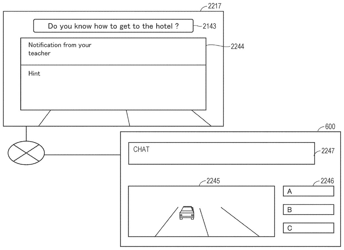
The virtual object generation module1425generates data on objects to be arranged in the virtual space11. The objects include, for example, various situations to be used for learning a foreign language. Examples of such situations include, but are not limited to, airports, restaurants, banks, boutiques, hospitals, train stations, hotels, city halls, police stations, and the like.
The hand object management module1426may arrange a hand object in the virtual space11. The hand object corresponds to, for example, a right hand or a left hand of the user5holding the controller300.
The controller management module1427receives the motion by the user5in the virtual space11and controls the controller object in accordance with that motion. In at least one embodiment of this disclosure, the controller object functions as a controller for issuing commands to another object arranged in the virtual space11. In at least one aspect, the controller management module1427generates data for arranging in the virtual space11a controller object for receiving controls in the virtual space11. When the HMD120receives this data, the monitor130may display the controller object.
The space information1431stores one or more templates that are defined to provide the virtual space11.
The learning content1432includes a plurality of example sentences in English, Chinese, and other foreign languages. Each example sentence is data stored locally by the user5. In at least one aspect, each example sentence is stored in a cloud storage (e.g., server600). In at least one aspect, each of the plurality of example sentences is associated with one or more scenes in which that example sentence is to be used.
The user information1433contains, for example, identification information on the user5of the HMD120and an authority associated with the user5.
[Data Structure of Server]
The data structure of the server600is now described in detail with reference toFIG. 15.FIG. 15is a schematic diagram of one mode of storing data in the memory620of the server600according to at least one embodiment of this disclosure.
In at least one embodiment of this disclosure, the memory620stores tables1010,1020, and1030. The table1010includes one or more example sentences corresponding to each situation. The table1020includes user information. The table1030includes a user-specific word list.
The table1010includes columns of a situation1011, an example sentence ID1012, and an example sentence1013. The situation1011represents a scene in which a foreign language is used. The situation1011is defined, for example, by a creator of the content to be used in a service for supporting learning of a foreign language. The example sentence ID1012identifies the example sentence1013. The example sentence1013is prepared by the creator of the content. In at least one aspect, the same example sentence is used for two or more different situations.
The table1020includes columns of a user name1021, a user ID1022, a registration date1023, a final login date and time1024, and a status1025. The user name1021represents the user of the service. The user ID1022identifies the user. The registration date1023represents the date on which the user registered for the service. The final login date and time1024represents the date and time when the user last logged in to the service. The status1025indicates whether the user is currently online or offline.
The table1030includes columns of a user ID1031, a situation1032, an example sentence ID1033, a word1034, and a selection mode1035. The user ID1031identifies the user who registered a word. The situation1032represents the situation in which the word is used. The example sentence ID1033identifies an example sentence including the word. The word1034represents the word registered by the user. The selection mode1035represents an operation mode at a time when the word is registered. The selection mode1035may include, for example, a user selection, an automatic selection, and an instructor selection. The user selection indicates that the word has been selected by the user. The automatic selection indicates that a word has been selected by the server600. The instructor selection indicates that the word has been selected by the instructor of the user5(e.g., an English conversation teacher).
The processor610of the server600uses the data stored in the memory620to register a word for each user, or to present a registered word to the HMD120.
[Control Structure]
With reference toFIG. 16, the control structure of the HMD set110according to at least one embodiment of this disclosure is described.FIG. 16is a flowchart of processing to be executed by the HMD set100according to at least one embodiment of this disclosure.
In Step S1610, the processor210of the computer200serves as the virtual space definition module1424to identify virtual space image data and define the virtual space.
In Step S1620, the processor210initializes the virtual camera14. For example, in a work area of the memory, the processor210arranges the virtual camera14at the center defined in advance in the virtual space11, and matches the line of sight of the virtual camera14with the direction in which the user5faces.
In Step S1630, the processor210serves as the field-of-view image generation module1429to generate field-of-view image data for displaying an initial field-of-view image. The generated field-of-view image data is transmitted to the HMD120by a communication control module540via the field-of-view image generation module1429.
In Step S1632, the monitor130of the HMD120displays the field-of-view image based on the field-of-view image data received from the computer200. The user5wearing the HMD120may recognize the virtual space11through visual recognition of the field-of-view image.
In Step S1634, the HMD sensor410detects the position and the inclination of the HMD120based on a plurality of infrared rays emitted from the HMD120. The detection results are transmitted to the computer200as motion detection data.
In Step S1640, the processor210identifies a field-of-view direction of the user5wearing the HMD120based on the position and inclination of the HMD120. The processor210executes an application program, and arranges an object in the virtual space11based on a command contained in the application program.
In Step S1642, the controller300detects motion of the user5based on a signal output from the motion sensor420. In at least one aspect, the motion of the user5is detected based on an image from a camera arranged around the user5.
In Step S1650, the processor210receives, based on motion by the user5, an instruction to activate an application for supporting learning of a foreign language. This instruction is transmitted to the server600. When the server600activates the application, data for displaying a learning screen is transmitted from the server600to the computer200. When the computer200transmits the data to the HMD120, the user5may visually recognize the foreign language learning screen in the virtual space11.
In Step S1660, the processor210receives, based on motion by the user5, a selection of the situation the user5wishes to learn. For example, when the user5operates the controller300and selects a situation from a menu screen presented in the virtual space, data representing the selected situation is transmitted to the server600. When the server600receives that data, the server600transmits the data of the example sentences associated with the situation to the computer200.
In Step S1670, the processor210generates data for displaying an example sentence, and transmits the generated data as field-of-view image data to the HMD120.
In Step S1672, when the HMD120receives the field-of-view image data, the HMD120causes the monitor130to update the field-of-view image.
In Step S1674, the controller300detects motion by the user5based on a signal output from the motion sensor420. Similar to the case of Step S1642, in at least one aspect, the motion by the user5is also detected based on an image from a camera arranged around the user5. In this case, the motion by the user5may be, for example, selection of a selected word in a situation selected by the user5. When the user5selects a word in the virtual space, data identifying the selected word is transmitted to the server600.
In Step S1680, the processor210detects an instruction for storing the word selected by the user5in the word list. When this instruction is detected, the computer200transmits to the server600the user ID and an instruction to store the word. The server600stores the word as a word associated with the user5in a word list (e.g., table1030) based on that instruction. When storage of the word is complete, the server600transmits a message notifying that fact to the computer200.
In Step S1690, the processor210generates a message indicating that the word has been stored, and transmits the generated message to the HMD120as field-of-view image data.
In Step S1692, the HMD120updates the field-of-view image based on the received field-of-view image data, and displays the updated field-of-view image on the monitor130. Based on the message, the user5recognizes that the selected word has been stored.
The notification that storage of the word is complete is not limited to a message. For example, in at least one aspect, a signal indicating that the word has been stored is transmitted to the controller300, and the controller300vibrates based on that signal.
With reference toFIG. 17, a description is given in detail of a control structure of the server600.FIG. 17is a flowchart of processing to be executed by the server600according to at least one embodiment of this disclosure.
In Step S1710, the processor610starts execution of an application program based on an instruction given by the user5.
In Step S1715, the processor610generates data for displaying the virtual space on the HMD120, and transmits the generated data to the HMD120via the computer200.
In Step S1720, the processor610detects motion of the user5in the real space based on the signal transmitted from the controller300. For example, the processor610detects input of login information for accessing a service for supporting foreign language learning. The login information may be, for example, a registered user ID and password.
In Step S1725, the processor610determines whether or not the user5is a registered user based on the login information transmitted from the user5and the user information (e.g., table1020) registered in the server600. When the user5is a registered user, the processor610generates data for displaying the foreign language learning screen in the virtual space presented by the HMD120worn by the user5, and transmits the generated data to the HMD120.
In Step S1730, the processor610generates data for displaying in the virtual space a screen prompting situation selection, and transmits the generated data to the HMD120. When the user5selects a situation in the virtual space, information for identifying the selected situation is transmitted from the HMD120to the server600.
In Step S1735, the processor610displays in the virtual space of the HMD120an example sentence corresponding to the situation selected by the user5. When the user5operates the controller300and selects a word from the example sentence, data identifying that word is transmitted to the server600.
In Step S1740, the processor610detects that a word has been selected by the user5.
In Step S1745, the processor610stores the word selected by the user5in a word list (e.g., table1030) for each user.
In Step S1750, the processor610generates data for displaying in the virtual space a message notifying that the word has been registered, and transmits the generated data to the HMD120via the computer200. When the HMD120receives the data, a message is displayed on the monitor130. The user5is able to recognize the message in the virtual space.
In Step S1755, the processor610detects motion by the user5in the real space based on a signal from the controller300. When the motion is an instruction to continue the application, the control returns to Step S1735. When the motion is an instruction to end the application, the application program ends. When the motion is another instruction, the control advances to Step S1760.
In Step S1760, the processor610executes the processing associated with the motion.
The control structure of the server600is now further described with reference toFIG. 18.FIG. 18is a flowchart of processing executed in response to the processor610of the server reading a word according to at least one embodiment of this disclosure.
In Step S1810, the processor610starts execution of the application program based on detection of an instruction by the user5to read a word.
In Step S1815, the processor610generates data for displaying the virtual space, and transmits the generated data to the HMD120via the computer200.
In Step S1820, the processor610detects motion of the user in the real space based on the signal transmitted from the controller300.
In Step S1825, the processor610displays the foreign language learning screen in the virtual space based on the motion by the user5.
In Step S1830, the processor610displays in the virtual space, based on motion by the user5, a screen prompting selection of a situation to learn a foreign language. The screen may be, for example, a screen displaying icons representing each of a plurality of situations in a menu format. When the user5wearing the HMD120operates the controller300and selects a situation (e.g., airport), data for identifying the selected situation is transmitted from the HMD120to the server600.
In Step S1835, the processor610identifies the situation selected by the user5based on the situation ID included in the signal from the HMD120.
In Step S1840, the processor610reads the word registered associated with the selected situation from the memory module620, and generates data for displaying that word in the virtual space. The generated data is transmitted to the HMD120. When the HMD120receives the data, the monitor130displays the word. The user5is able to recognize the word displayed in the virtual space. For example, when the user5has registered a word he/she wishes to memorize, that word may be displayed in the virtual space. When that word is easily recollected by the user5, the user5operates the controller300and, for example, may select a “confirmed” icon displayed in the virtual space. A signal representing the selection is transmitted to the server600from the HMD120that received the input of the controller300.
In Step S1845, when the signal transmitted from the HMD120is received, the processor610detects that a confirmation result of the word has been input. Based on the signal, the processor610changes the status of that word associated with the user5, for example, from “memorization required” to “memorized”.
In Step S1850, the processor610detects motion by the user5in the real space based on a signal from the HMD120. For example, when the user5operates the controller300, a signal corresponding to that operation is transmitted from the HMD120. More specifically, in at least one aspect, when the user5operates the controller300and inputs a command to delete a learned word to the controller300, the HMD120, which has received the input from the controller300, transmits to the server600a signal including the command and identification data on the word. When the user inputs another command to the controller300, a signal corresponding to that command is transmitted from the HMD120to the server600.
In Step S1855, the processor610determines whether or not to delete the registered word based on a signal transmitted from the HMD120in accordance with motion by the user5. In response to the processor610confirming that the signal is an instruction to delete the word (YES in Step S1855), the processor610switches the control to Step S1860. Meanwhile, when the processor610confirms that the signal is not an instruction to delete the word (NO in Step S1855), the processor610switches the control to Step S1865.
In Step S1860, the processor610deletes a record including the word that had been registered in the word list (e.g., table1030).
In Step S1865, the processor610executes another process associated with motion by the user5.
Screens displayed to the user5are now described with reference toFIG. 19toFIG. 25.FIG. 19is a diagram of a field-of-view image1917displayed on the monitor130according to at least one embodiment of this disclosure. The field-of-view image1917represents, for example, an initial screen of an application program for learning a foreign language in the virtual space. The initial screen is displayed, for example, when input by the user5of the user ID and the password is complete and authentication is successful.
In the example ofFIG. 19, there is displayed a screen for learning English. The screen includes the user ID (=ABC) of the user5and the date and time of the last time the user logged in. When the user5selects an icon1941and inputs an instruction “continue”, the field-of-view image1917switches to the screen for selecting a situation.
InFIG. 20, there is a field-of-view image2017for prompting selection of any one situation from a plurality of situations. The field-of-view image2017is displayed on the monitor130based on a signal received from the server600. A plurality of situations are prepared in advance by the provider of the service. In at least one aspect, one or more situations is presented as initial candidates in accordance with a preference selected by the user5. In at least one aspect, the user5selects a situation as desired.
In the example inFIG. 20, when the user5operates the controller300and selects an icon2042, “airport” is selected as the situation. A signal indicating that “airport” has been selected as the situation is transmitted from the HMD120to the server600. Then, example sentences corresponding to the selected situation are transmitted from the server600to the HMD120. The HMD120displays each example sentence on the monitor130.
InFIG. 21, there is a visual image2117for supporting self-learning according to at least one embodiment of this disclosure. For example, in a case in which a self-learning mode and an automatic mode are defined in advance as the learning modes of the foreign language, when the user5selects the self-learning mode, the server600displays an example sentence2143corresponding to the selection result. When the user5visually recognizes the example sentence2143and recognizes an unknown word, the user5is able to select that word. For example, the user5is able to select the word by operating the controller300and placing a pointer object on the example sentence2143presented in the virtual space. In at least one aspect, the user5directs his/her line of sight at the example sentence2143, places his/her point of gaze on a word, and selects that word in accordance with a detection result of the sight line at that time. The method of selecting a word based on the line of sight of the user5may be performed by, for example, selecting the word in accordance with the line of sight of the user5detected based on output from the eye gaze sensor140, or selecting the word by taking a reference line of sight16determined based on the direction of the virtual camera14(i.e., direction determined by movement of the head of the user wearing the HMD120) to be the line of sight of the user5. For example, a word may be determined as having been selected when the word and an icon indicating the reference line of sight16displayed on the monitor130overlap for a fixed period or more.
InFIG. 22, there is an example of a mode in which the user5learns in a chat format while receiving instruction from a teacher according to at least one embodiment of this disclosure. For example, the HMD120presenting a field-of-view image2217is connected to the server600. The user5wearing the HMD120visually recognizes the field-of-view image2217. The server600is used by the teacher.
In the HMD120, the field-of-view image2217includes an example sentence2143and a message2244. The message2244may include a comment (chat) and a hint from the teacher. For example, when the teacher using the server600operates a keyboard to input a message and a hint, and designates a destination, the message and the hint are transmitted to only the user5.
In the server600, the monitor to be viewed by the teacher includes an area2245for transferring students (for example, user5), an area2246representing logged-in users, and an area2247for receiving input of a chat. The area2245may display, for example, an image photographed by a camera arranged near the user5. When a user is selected by the teacher, the area2246receives an instruction to transmit comments and hints to only the selected user. The area2247receives comments and chat inputs from a keyboard or via speech.
A mode of selecting a word from an example sentence is now described with reference toFIG. 23.FIG. 23is a diagram of a mode in which a word is selected from the field-of-view image2317presented on the HMD120according to at least one embodiment of this disclosure.
In at least one aspect, the field-of-view image2317includes an example sentence2143. In this case, the HMD120divides the example sentence2143into words by using the spaces (i.e., gaps between words) included in the example sentence2143transmitted from the server600, and temporarily stores each word as text data. The example sentence2143is arranged in the virtual space as a set of word objects based on such text data.
When the user5operates the controller300or performs another motion in the real space, a pointer corresponding to that motion is presented in the virtual space. When a predetermined determination button is pressed on the controller300while the pointer overlaps a word object, that word object is selected as a word to be registered in the word list, and is stored in the word list (e.g., table1030).
In at least one aspect, when a hand object is presented in the virtual space in accordance with operation of the controller300by the user5, the hand object holds the word object. In this case, the word corresponding to the word object held by the hand object is stored in the word list (table1030).
In the example inFIG. 23, word objects2348and2349are selected as words to be registered in the word list.
Viewing of the words registered in the word list is now described with reference toFIG. 24.FIG. 24is a schematic diagram of a mode in which a word object is presented in the field-of-view image2417according to at least one embodiment of this disclosure.
The user5may also temporarily stop the learning of the foreign language and resume the learning on another day. In that case, when there are words registered in the word list, based on the database accumulated for the user who logs in on the another day, the server600reads those words and transmits the word data to the HMD120. The HMD120may present word objects based on that data in the virtual space. For example, when the user5selects a situation and instructs the HMD120to refer to a word, the instruction is transmitted from the HMD120to the server600. In response to that instruction, the server600reads the word associated with the situation selected by the user5from the table1030, and transmits the word data to the HMD120.
In the example inFIG. 24, the field-of-view image2417presents five word objects previously registered during learning of a specific situation (e.g., airport). Of those five word objects, the word objects2348and2349correspond to the words registered by the user5at the time of learning (FIG. 23). In such a configuration, even when learning is interrupted, each user is able to easily refer to the words that have been registered so far, and hence learning can be resumed seamlessly.
Training for each separate situation is now described with reference toFIG. 25.FIG. 25is a diagram of a field-of-view image2517at a time when learning is started in the situation selected by the user5according to at least one embodiment of this disclosure.
When the user5selects on the menu screen of the application program to start training, a situation selection screen is presented in the virtual space. When the user5selects “airport” as the situation, the data representing the selected situation is transmitted to the server600. The server600reads a word associated with the situation “airport” based on the identification data of the user5and the data identifying the situation, and transmits the data (e.g., text data) of that word to the HMD120. When the HMD120receives the data from the server600, the HMD120presents an object2551representing the situation and an object2552of the word associated with the situation in a virtual space in a mode different from the display mode of other objects.
The technical features of at least one embodiment disclosed above are summarized in the following manner, for example.
(Configuration 1)
According to at least one embodiment of this disclosure, there is provided a method to be executed on a computer (e.g., server600) to display content in a virtual space11. The method includes selecting, based on motion by a user5wearing an HMD120, a situation to be developed in a virtual space11from among a plurality of situations (airport, restaurant, and other situations) defined in advance. The method further includes presenting, based on motion by the user5, one or more words associated with the situation. The method further includes selecting any one of the one or more words based on an instruction issued to the server600. The method further includes registering the selected situation and the selected word in a word list (e.g., table1030).
(Configuration 2)
According to at least one embodiment of this disclosure, the method further includes presenting a word registered in the word list in the virtual space11.
(Configuration 3)
According to at least one embodiment of this disclosure, the method further includes selecting a situation for learning a word from among the plurality of situations. The method further includes presenting a word associated with the selected situation in the virtual space11.
(Configuration 4)
According to at least one embodiment of this disclosure, the selecting of any one of the one or more words includes presenting in the virtual space11an object (e.g., point-of-gaze object and virtual hand object) based on motion by the user5in the real space. The method further includes selecting, by the object, the word to be selected, based on motion by the user5.
(Configuration 5)
According to at least one embodiment of this disclosure, the selecting of any one of the one or more words includes detecting a line of sight of the user5; and identifying a word at which the line of sight of the user5is directed.
(Configuration 6)
According to at least one embodiment of this disclosure, the selecting of any one of the one or more words includes selecting the word based on a command by an instructor of the user5.
(Configuration 7)
According to at least one embodiment of this disclosure, the selecting of any one of the one or more words includes selecting a word that fails to satisfy an answer criterion determined in advance. For example, a word that is frequently mistaken by the user5is selected as the word to be stored in the word list.
(Configuration 8)
According to at least one embodiment of this disclosure, the method further includes presenting a hint for one or more words.
(Configuration 9)
According to at least one embodiment of this disclosure, the presenting of the hint includes presenting the hint based on an instruction by the user5or based on an operation by the instructor.
(Configuration 10)
According to at least one embodiment of this disclosure, the presenting of the hint includes presenting the hint when an answer determined in advance for any one of the one or more words is not obtained within a period of time determined in advance. For example, the hint may be presented in the virtual space11when the user5cannot provide the correct answer for the meaning of the word presented in the virtual space11within a period of time determined in advance.
As described above, in at least one embodiment, each user is able to select a situation and learn a foreign language for each selected situation. For example, each user is able to learn one or more example sentences prepared in advance in accordance with the situations and, if necessary, store the words forming the example sentences in a cloud storage (e.g., server600). The stored words may be displayed in the virtual space in response to a request by the user5. In this way, the user5is able to learn the example sentences of the foreign language while experiencing the situation in the virtual space. The example sentences are associated with situations, and hence memorization of the example sentences and the words is easier, which increases the learning effect.
In the embodiment described above, the description is given by exemplifying the virtual space (VR space) in which the user is immersed using an HMD. However, a see-through HMD may be adopted as the HMD. In this case, the user may be provided with a virtual experience in an augmented reality (AR) space or a mixed reality (MR) space through output of a field-of-view image that is a combination of the real space visually recognized by the user via the see-through HMD and a part of an image forming the virtual space. In this case, action may be exerted on a target object in the virtual space based on motion of a hand of the user instead of the operation object. Specifically, the processor may identify coordinate information on the position of the hand of the user in the real space, and define the position of the target object in the virtual space in connection with the coordinate information in the real space. With this, the processor can grasp the positional relationship between the hand of the user in the real space and the target object in the virtual space, and execute processing corresponding to, for example, the above-mentioned collision control between the hand of the user and the target object. As a result, an action is exerted on the target object based on motion of the hand of the user.
It is to be understood that the above described embodiments disclosed herein are merely examples in all aspects and in no way intended to limit this disclosure. The scope of this disclosure is defined by the appended claims and not by the above description, and it is intended that this disclosure encompasses all modifications made within the scope and spirit equivalent to those of the appended claims.
Claims
- A method, comprising: defining a virtual space, wherein the virtual space comprises a plurality of first objects and a second object;defining a plurality of situations to be developed in the virtual space;associating each situation of the plurality of situations with a corresponding first object of the plurality of first objects;detecting motion by a user associated with a head-mounted display (HMD);moving the second object in accordance with the detected motion;selecting a first object of the plurality of first objects using the second object;updating the virtual space to a virtual space corresponding to a situation of the plurality of situations corresponding to the selected first object;displaying in the virtual space a plurality of words associated with the corresponding situation;selecting at least one word of the plurality of words based on the detected motion;and associating the selected at least one word with the selected situation and registering the associated at least one word in a word list.
- The method according to claim 1 , further comprising displaying in the virtual space a word registered in the word list.
- The method according to claim 1 , further comprising: identifying, from the plurality of situations, a situation associated with the at least one word registered in the word list;updating the virtual space to the identified situation;and presenting in the updated virtual space the word associated with the situation in the word list.
- The method according to claim 1 , further comprising: associating each word of the plurality of words with a corresponding third object of a plurality of third objects in the virtual space;selecting a third object of the plurality of third objects using the second object;and selecting a word of the plurality of words corresponding to the selected third object.
- The method according to claim 1 , further comprising: selecting a first object of the plurality of first objects based on a detected line of sight of the user;and identifying a word of the plurality of words corresponding to the selected first object.
- The method according to claim 1 , further comprising: receiving a command by a second user, the command comprising information for designating the plurality of words;and presenting in the updated virtual space, among the plurality of words associated with the situation, the plurality of words designated in accordance with the command.
- The method according to claim 1 , wherein the plurality of words comprise at least one word that satisfies an answer criterion determined in advance and at least one word that fails to satisfy the answer criterion.
- The method according to claim 1 , further comprising: displaying on the HMD an example sentence associated with the plurality of words;displaying a first word of the plurality of words that satisfies the answer criterion for the example sentence;displaying a second word of the plurality of words that fails to satisfy the answer criterion;and displaying a hint for the example sentence.
- The method according to claim 8 , wherein the displaying of the hint comprises displaying the hint in accordance with an instruction from the user.
- The method according to claim 8 , wherein the displaying of the hint comprises displaying the hint in accordance with an operation by a second user.
- The method according to claim 8 , further comprising presenting the hint on the HMD in response to a failure to select the at least one word satisfying the answer criterion within a period of time selected in advance.
- A system, comprising: a head-mounted display (HMD);a processor;and a non-transitory computer readable medium connected to the processor, wherein the non-transitory computer readable medium is configured to store a program, and the processor is configured to execute the program for: defining a virtual space, wherein the virtual space comprises a plurality of first objects and a second object;receiving a plurality of situations to be developed in the virtual space;associating each situation of the plurality of situations with a corresponding first object of the plurality of first objects;detecting motion by a user associated with the HMD;moving the second object in accordance with the detected motion;selecting a first object of the plurality of first objects using the second object;updating the virtual space to a virtual space corresponding to a situation of the plurality of situations corresponding to the selected first object;instructing the HMD to display, in the virtual space, a plurality of words associated with the corresponding situation;selecting at least one word of the plurality of words based on the detected motion;and associating the selected at least one word with the selected situation and registering the associated at least one word in a word list.
- The system according to claim 12 , wherein the processor is further configured to instruct the HMD to display, in the virtual space, a word registered in the word list.
- The system according to claim 12 , wherein the processor is further configured to execute the program for: identifying, from the plurality of situations, a situation associated with the at least one word registered in the word list;updating the virtual space to the identified situation;and instructing the HMD to display, in the updated virtual space, the word associated with the situation in the word list.
- The system according to claim 12 , wherein the processor is further configured to execute the program for: associating each word of the plurality of words with a corresponding third object of a plurality of third objects in the virtual space;selecting a third object of the plurality of third objects using the second object;and selecting a word of the plurality of words corresponding to the selected third object.
- The system according to claim 12 , wherein the processor is further configured to execute the program for: selecting a first object of the plurality of first objects based on a detected line of sight of the user;and identifying a word of the plurality of words corresponding to the selected first object.
- The system according to claim 12 , wherein the processor is further configured to execute the program for: receiving a command from a second user, the command comprising information for designating the plurality of words;and instructing the HMD to display, in the updated virtual space, among the plurality of words associated with the situation, the plurality of words designated in accordance with the command.
- The system according to claim 12 , wherein the plurality of words comprise at least one word that satisfies an answer criterion determined in advance and at least one word that fails to satisfy the answer criterion.
- The method according to claim 12 , wherein the processor is further configured to execute the program for: instructing the HMD to display an example sentence associated with the plurality of words;instructing the HMD to display a first word of the plurality of words that satisfies the answer criterion for the example sentence;instructing the HMD to display a second word of the plurality of words that fails to satisfy the answer criterion;and instructing the HMD to display a hint for the example sentence.
- The system according to claim 19 , wherein the processor is further configured to execute the program for instructing the HMD to display the hint in response to a failure to select the at least one word satisfying the answer criterion within a period of time selected in advance.
Disclaimer: Data collected from the USPTO and may be malformed, incomplete, and/or otherwise inaccurate.