U.S. Pat. No. 10,313,679
SYSTEMS AND METHODS FOR ENCODER-GUIDED ADAPTIVE-QUALITY RENDERING
AssigneeZeniMaz Media Inc.
Issue DateApril 20, 2018
U.S. Patent no. 10,313,679: Systems and methods for encoder-guided adaptive-quality rendering
U.S. Patent no. 10,313,679: Systems and methods for encoder-guided adaptive-quality rendering
Issued June 4, 2019, to ZeniMax Media Inc.
Priority Date April 21, 2017
Summary:
U.S. Patent No. 10,313,679 (the ‘679 Patent) relates to video rendering in video games. The current issue in video rendering and streaming relates to issues created by latency. This issue is particularly exacerbated in the context of video games as any delay can mean the difference between victory and failure in a video game context. In a system where gameplay video is rendered locally, but transmitted from a remote server the difference in quality between the video data that is transferred and then displayed locally can require a large amount of computation by the local machine. The ‘679 Patent details methods for optimizing this rendering by using a codec. The invention proceeds by identifying qualities of the rendered images and compares them with the pre-rendered images. The encoder then attempts to match of these images in order to improve computational costs on the local system while preserving quality. This invention attempts to improve a person’s ability to play video games remotely by improving the streaming quality of game data.
Abstract:
Systems and methods for improving computer technology related to the rendering and encoding of images are disclosed, preferably for use in a video-game environment. In certain embodiments, a codec is used to encode one or more reference images for a partial range of encoder settings and a renderer is used to generate one or more rendering quality-settings profiles, generate one or more reference images, calculate perceived qualities for each of the one or more reference images, re-render the one or more reference images for each of the one or more rendering quality-setting profiles, and calculate perceived qualities for each of the one or more re-rendered reference images. The renderer compares the perceived qualities of the reference images to the perceived qualities of the re-rendered images and matches them. Those matches result in an association of one or more encoder settings with their matching rendering quality-settings profiles into a look-up table. The lookup table is used to generate a rendered image at a substantially identical perceived quality to an encoded frame during gameplay.
Illustrative Claim:
1. A computer-implemented method for rendering, comprising the steps of: generating one or more rendering quality-settings profiles; generating one or more reference images; encoding the one or more reference images for a partial range of encoder settings; calculating a first perceived quality for each of the one or more reference images; re-rendering the one or more reference images for each of the one or more rendering quality-setting profiles; calculating one or more second perceived qualities for each of the one or more re-rendered reference images; comparing the one or more first perceived qualities to the one or more second perceived qualities, wherein a match between one or more first perceived qualities and the one or more second perceived qualities results in an association of one or more encoder settings with their matching rendering quality-settings profiles in one or more look-up tables; and generating a rendered image at a substantially identical perceived quality to an encoded frame on the basis of the look-up table.
Illustrative Figure
Abstract
Systems and methods for improving computer technology related to the rendering and encoding of images are disclosed, preferably for use in a video-game environment. In certain embodiments, a codec is used to encode one or more reference images for a partial range of encoder settings and a renderer is used to generate one or more rendering quality-settings profiles, generate one or more reference images, calculate perceived qualities for each of the one or more reference images, re-render the one or more reference images for each of the one or more rendering quality-setting profiles, and calculate perceived qualities for each of the one or more re-rendered reference images. The renderer compares the perceived qualities of the reference images to the perceived qualities of the re-rendered images and matches them. Those matches result in an association of one or more encoder settings with their matching rendering quality-settings profiles into a look-up table. The lookup table is used to generate a rendered image at a substantially identical perceived quality to an encoded frame during gameplay.
Description
DETAILED DESCRIPTION OF THE PREFERRED EMBODIMENTS In describing a preferred embodiment of the invention illustrated in the drawings, specific terminology will be resorted to for the sake of clarity. However, the invention is not intended to be limited to the specific terms so selected, and it is to be understood that each specific term includes all technical equivalents that operate in a similar manner to accomplish a similar purpose. Several preferred embodiments of the invention are described for illustrative purposes, it being understood that the invention may be embodied in other forms not specifically shown in the drawings. Modern rendering engines, such as those used in video games, have the ability to adapt certain quality settings during runtime based on factors such as a player's distance from an object, the rendering time of the previous frame, or other runtime measurements. A rendering engine may provide several methods to adjust quality, allowing for more granular control of the overall rendered quality. Some examples include biasing texture sampling to use blurrier mipmaps, using lower quality cascades or fewer samples on shadows, running a simplified path on the shading model (e.g. DCT-transforms of specular to look like diffuse), and using fewer samples for post processing (e.g. for Gaussian, volumetric fog, etc.). In live-streaming applications, altering one or more rendering quality settings in response to changes in encoder settings may provide the best rendering-cost savings without impacting the encoded output quality. FIG. 1is a diagram of an exemplary environment in which real-time rendered video is livestreamed to a remote viewer. The server100may be any hardware capable of simultaneously running a real-time rendering process102(also referred to as a renderer below) and a streaming codec104. The codec104must also have the ability to communicate its quantization settings back to the rendering process102through direct reporting or some other ...
DETAILED DESCRIPTION OF THE PREFERRED EMBODIMENTS
In describing a preferred embodiment of the invention illustrated in the drawings, specific terminology will be resorted to for the sake of clarity. However, the invention is not intended to be limited to the specific terms so selected, and it is to be understood that each specific term includes all technical equivalents that operate in a similar manner to accomplish a similar purpose. Several preferred embodiments of the invention are described for illustrative purposes, it being understood that the invention may be embodied in other forms not specifically shown in the drawings.
Modern rendering engines, such as those used in video games, have the ability to adapt certain quality settings during runtime based on factors such as a player's distance from an object, the rendering time of the previous frame, or other runtime measurements. A rendering engine may provide several methods to adjust quality, allowing for more granular control of the overall rendered quality. Some examples include biasing texture sampling to use blurrier mipmaps, using lower quality cascades or fewer samples on shadows, running a simplified path on the shading model (e.g. DCT-transforms of specular to look like diffuse), and using fewer samples for post processing (e.g. for Gaussian, volumetric fog, etc.). In live-streaming applications, altering one or more rendering quality settings in response to changes in encoder settings may provide the best rendering-cost savings without impacting the encoded output quality.
FIG. 1is a diagram of an exemplary environment in which real-time rendered video is livestreamed to a remote viewer. The server100may be any hardware capable of simultaneously running a real-time rendering process102(also referred to as a renderer below) and a streaming codec104. The codec104must also have the ability to communicate its quantization settings back to the rendering process102through direct reporting or some other monitoring process known in the art. The encoded video stream is transmitted over a network to a client device106. The client106may be any hardware capable of decoding and displaying the video stream.
FIG. 2is a flow diagram outlining the exemplary stages of encoder-guided adaptive-quality rendering. Livestream encoding using an H.264 standard-compliant encoder typically employs a Constant Rate Factor (“CRF”) mode which reports the effective quantization settings for an encoded frame as a quantization parameter (“QP”) at “REPORTQUANTIZATIONSETTINGS FOREACHENCODEDFRAME,” step200. In certain embodiments, the H.264 standard compliant library used is ffmpeg, which outputs the quantization parameter as the variable, f_crf_avg. The quantization parameter is an index, ranging from 0 to 51, which defines how lossy the compression is during encoding. Lower values of QP represent lower compression while higher values of QP represent higher compression. In order to remain at a constant bitrate, an encoder operating in CRF mode will increase the QP for frames which can afford higher compression and decrease the QP for frames that require higher quality. The encoder takes advantage of the fact that the human eye is less able to distinguish detail on moving objects by increasing compression in areas which have comparatively high motion and decreasing compression in areas which are relatively still. This allows the encoder to maintain a target perceived quality while reducing the size of some encoded frames.
The renderer reads the reported QP before rendering a frame at “MONITORQUANTIZATIONSETTINGS FORCHANGES,” step202. At “DIFFERENT?,” step203, if the effective quantization settings have not changed since the previously rendered frame, the renderer takes no action to adapt rendering quality and will check again on the next frame. If the renderer reads a QP value which is different than the previously rendered frame, or if this is the first encoded frame for which encoder-guided adaptive-quality rendering is being performed, the rendering quality is altered at “CHANGERENDERINGQUALITYSETTINGS TOMATCHQUANTIZATIONSETTINGS,” step204. If the QP value has increased since the previously rendered frame, the renderer will lower the quality to match the compression level at the encoder. Likewise, if the QP value has decreased since the previously rendered frame, the encoder will increase the quality. To change the rendering settings, the renderer will check a pre-generated lookup table that provides a rendering quality-settings profile for the encoder-provided QP value. In general, there should be only one entry per encoder quality setting. The renderer uses the encoder-provided QP, finds the one entry, and uses the associated rendering quality-settings profile. In general, the entire rendering quality-settings profile is applied. A rendering quality-settings profile is defined as a list of values for each available rendering quality setting. The pre-generation of this lookup table is described in more detail in reference toFIG. 3. The pre-defined lookup table may define rendering settings for integer-values of QP, which requires the renderer to round the read QP value to the nearest integer, or the lookup table may define rendering settings for each partial range of QP values between 0 and 51. The examples inFIG. 4andFIG. 5assume the renderer will round the QP to the nearest integer before using the lookup table, but the examples may be modified to define a lookup table using partial ranges of QP instead. The renderer will alter the quality settings according to the rendering quality-settings profile fetched from the lookup table before rendering the next frame. Reducing rendering quality will reduce the amount of rendering work that is wasted when the encoder bottlenecks the quality.
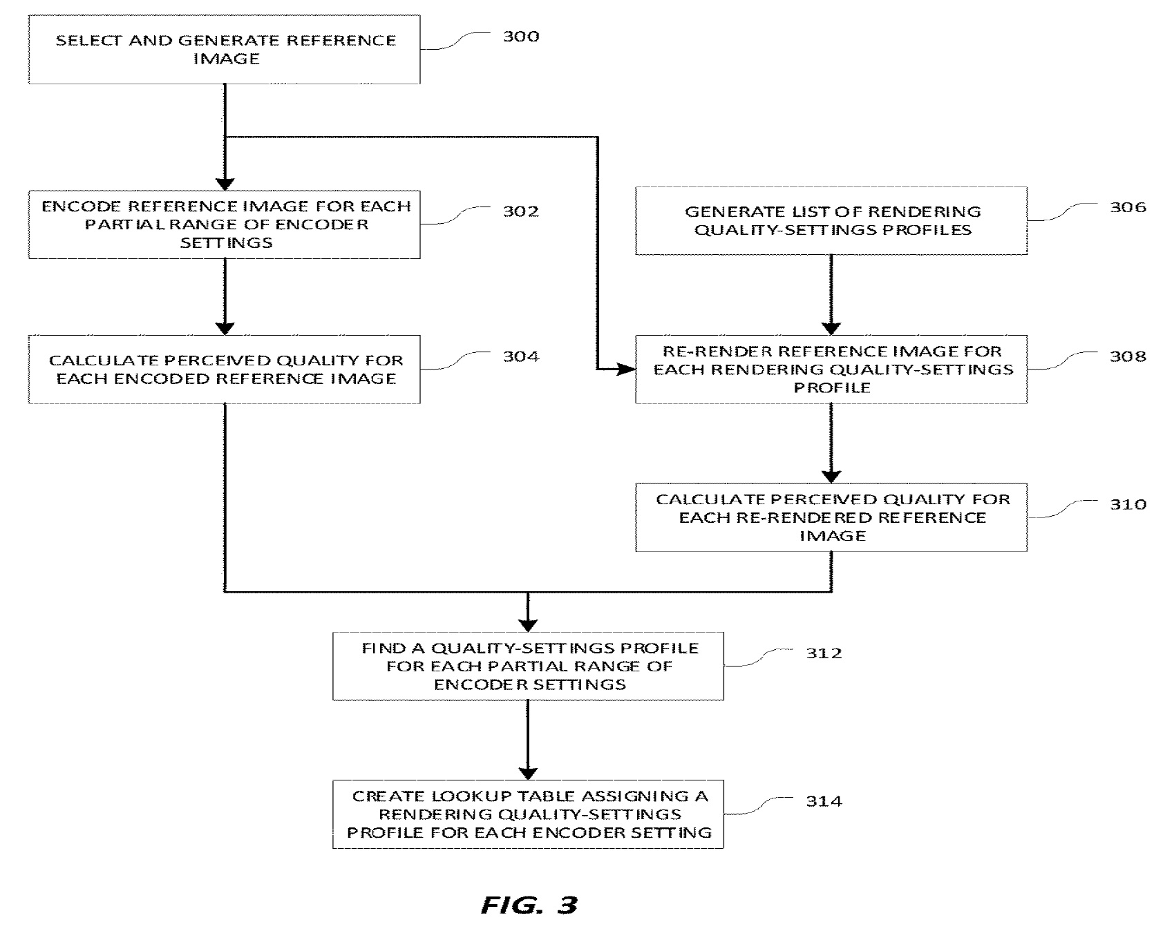
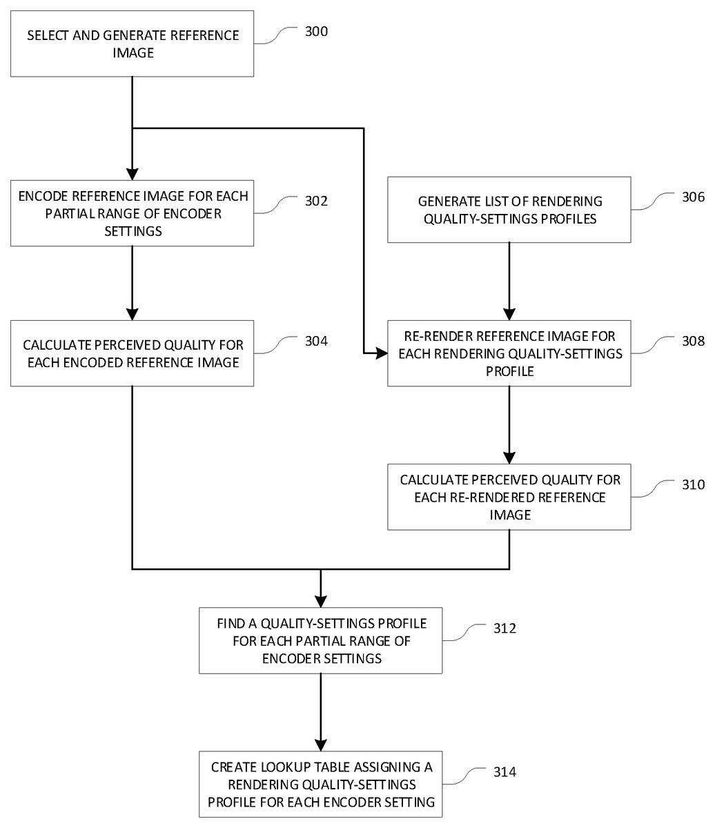
FIG. 3is a flow diagram outlining the exemplary pre-generation of the lookup table that assigns a rendering quality-settings profile to each partial range of the encoder settings. A reference image will be used as a baseline to measure the effects on perceived quality as the encoding settings or rendering settings are changed. The reference image should represent a typical frame of video output and include rendered elements such as models, textures, or visual effects that are typical to a chosen game context. The game context might include a specific area, specific map, specific level, or some specific gameplay. The selected reference image will be used to generate a lookup table that estimates the perceived quality of video rendered within the same context as the reference image. For example, the lookup table generated from a reference image that contains a representative set of elements from a game level may be used to estimate the perceived quality of video rendered from similar scenes within the same level. Methods for combining multiple lookup tables into a generalized lookup table are discussed further below. After a game context is identified, a representative scene should be chosen and rendered at full quality, as shown at “SELECT AND GENERATEREFERENCEIMAGE” step300. The full-quality rendered scene of the representative scene is referred to herein as the reference image.
A preferred embodiment of the runtime behavior of the renderer, discussed above in connection with the description ofFIG. 2, requires the renderer to round the received values of QP to the nearest integer before reading the lookup table. As a result, the lookup table will be generated using only integer-values of QP. At the encoder, the full-quality reference image is encoded for each integer-valued quality setting in the encoder, quantization parameter (QP) integer values 0 through 51, as shown at “ENCODEREFERENCEIMAGEFOREACHPARTIALRANGEOFENCODERSETTINGS,” step302. In the preferred embodiment, there are 52 partial ranges which are defined by the rounding operation performed by the renderer. The implementation can be modified to create more partial ranges for the more-common QP values, values in the middle of the range from 0 to 51, or fewer partial ranges for the more-rare QP values, values at the extremes of the range from 0 to 51.
Perceived quality is an attempt to quantify how well the human eye can perceive quality loss between a compressed image and the full-quality source image. There are several methods used to estimate perceived quality, including mean squared error (MSE) and peak signal-to-noise ratio (PSNR), which use only the luminance and contrast value differences between two images to calculate the quality of a compression codec. As disclosed by Z. Wang, A. C. Bovik, H. R. Sheikh and E. P. Simoncelli, “Image quality assessment: From error visibility to structural similarity,”IEEE Transactions on Image Processing, vol. 13, no. 4, pp. 600-612, April 2004, the structural similarity (SSIM) index is a method which adds the assumption that the human eye is also adept at extracting structural information from a scene and defines a calculation to estimate perceived quality. SSIM works by comparing pixel-data between two images: the uncompressed full-quality reference image to the encoded image. The algorithm compares the luminance, contrast, structure, and sometimes chrominance over “windows” of 8×8 pixels. Because SSIM has a low computation cost and outperforms methods like MSE and PSNR, it is the preferred tool for calculating perceived quality. To generate the perceived quality for each value of the encoder settings, preferably at the renderer and/or the game engine, the SSIM index is calculated between each encoded reference image and the reference image as shown at “CALCULATEPERCEIVEDQUALITYFOREACHENCODEDREFERENCEIMAGE,” step304. In the preferred embodiment, 52 SSIM values are calculated, one for each quantization parameter (QP) integer, with a value of 0 through 51. The exemplary descriptions in reference toFIG. 3,FIG. 4, andFIG. 5use a standard SSIM calculation to compare two still images, but there are SSIM method variants which can compare two video segments and which may be used instead at an increased computational cost. One such SSIM variant is the Spatio-Temporal SSIM as disclosed by Anush K. Moorthy and Alan C. Bovik, “Efficient Motion Weighted Spatio-Temporal Video SSIM Index,”Human Vision and Electronic Imaging XV, vol. 7527, March 2010 (available at http://live.ece.utexas.edu/publications/2010/moorthy_spie_jan10.pdf).
The renderer may have several settings available for per-pixel-quality control including screen resolution, mipmap selection, level-of-detail (LOD) selection, shadow quality, post-processing quality, or other settings. A quality-settings profile is defined as a list of values for each available quality setting. In certain embodiments, at the renderer, a list of all rendering settings which can be adaptively altered, along with their possible values, are gathered. Then all permutations of adaptive quality rendering settings and their values are generated to create a list of rendering quality-settings profiles, as shown at “GENERATELISTOFRENDERINGQUALITY-SETTINGSPROFILES,” step306. Since a renderer may have many quality settings with many possible values, the number of permutations of quality-settings profiles may be prohibitively long. The example ofFIG. 5discusses an exemplary method for limiting and optimizing the number of quality-settings profiles in the list.
For each rendering quality-settings profile in the list, the reference image should be re-rendered at the renderer using the specified rendering settings, as shown at “RE-RENDERREFERENCEIMAGEFOREACHRENDERINGQUALITY-SETTINGSPROFILE,” step308. If the rendering quality-settings profiles are comprised of more than one setting, the rendering times for each re-rendered reference image should also be recorded as a measure of computation cost, exemplarily measured in rendering time or clock-cycles. This measure of computational cost may be used in a later step as a tie-breaker if there are any SSIM value collisions.
Using the same measure of perceived quality as previously used in step304, the perceived quality is measured by comparing each of the re-rendered images to the original reference image, as shown at “CALCULATEPERCEIVEDQUALITYFOREACH RE-RENDEREDREFERENCEIMAGE,” step310. In the preferred embodiment, the structural similarity index (SSIM) is used to measure the perceived quality of the encoder results and will be used to measure the perceived quality of the re-rendering results.
At the renderer, the two sets of perceived quality values, the SSIM values for the encoded reference images calculated at step304and the SSIM values for the per-profile re-rendered reference images calculated at step310, are compared across both image sets to find matching SSIM values between the two sets. Ideally, for each encoded reference image's SSIM value, there is one exact matching SSIM value from the set of per-profile re-rendered images. If there are no exact matches, the chosen per-profile re-rendered image's SSIM value should be both greater than and as close as possible to the target encoded reference image's SSIM value. The matching SSIM values across both sets of perceived quality values will identify a rendering quality-settings profile for each value of QP, as shown at “FIND AQUALITY-SETTINGSPROFILEFOREACHPARTIALRANGEOFENCODERSETTINGS,” step312. In cases where there is a collision, where there are two or more exact matches from the set of SSIM values for the per-profile re-rendered images, the computational costs recorded in step308may be used as a tie-breaker and the less costly rendering quality-settings profile selected for the encoder setting.FIG. 5shows an example collision.
The encoder settings and their matching rendering quality-settings profiles should be organized into a lookup table as shown at “CREATELOOKUPTABLEASSIGNING ARENDERING-QUALITY-SETTINGSPROFILEFOREACHENCODERSETTING,” step314. This lookup table may be used during runtime at the renderer to change the rendering quality settings to match the quantization settings as described by step204inFIG. 2. The lookup table provides a rendering quality-settings profile that generates an image of the same perceived quality as the encoded frame and provides the largest computational savings for the given reference frame. Example lookup tables are shown inFIG. 4andFIG. 5.
The lookup table generated by the method described in connection withFIG. 3may be used within similar game contexts, scenes, or environments as the reference image. The process outlined in connection withFIG. 3may be repeated for several reference images, each representative of a particular environment, scene type, or other meaningful game context. For example, a reference image may be selected from each map in a game to generate multiple map-specific lookup tables. Lookup tables may also be combined to create a lookup table that can be more generally used in the game environment. For example, map-specific lookup tables may be combined to generate one lookup table that may be used for all maps in a game. To combine lookup tables, the rendering quality-settings profiles for each QP may be combined to find an average value for each setting contained in the profile. For example, three lookup tables are generated for three reference images. The rendering quality-settings profiles are comprised of three settings values: a post-processing quality setting, a shadow quality setting, and a resolution setting. To combine the rendering quality-settings profiles for a QP value of 4, the profiles are read from each lookup table and are represented as P41={3, MED, 95%}, P42={4, LOW, 90%}, and P43={2, MED, 90%}. The average values are found for each setting to generate PAvg={3, MED, 92%}. A profile-averaging process should round up so that the rendering process is never generating images at a lower perceived quality level than the current encoding quality setting. The profiles are averaged for each value of QP and organized into a new lookup table.
FIG. 4is an example of lookup table generation for rendering quality-setting profiles which are comprised of only one setting. In this example, a single rendering quality setting is adapted in response to changes in encoder quality settings. The rendering of a first-person view of a 3D scene is adapted at the renderer by altering the resolution of the 3D portions of the view, shown at “3D VIEW”400, while the resolution of user interface (UI) elements, shown as “UI”402, is not altered to maintain readability of any player-facing text. This type of selective resolution-scaling is referred to as dynamic resolution scaling and is an increasingly common feature of rendering engines. The reference image, shown at “REFERENCEIMAGE”404, represents a single frame from a typical video output rendered in the highest possible resolution and is chosen in accordance with the guidelines outlined at step300ofFIG. 3. At the encoder, the reference image, shown at “REFERENCEIMAGE”404, is encoded for each integer-value of QP, as described in connection with step302ofFIG. 3, to generate a list of encoded reference images at “ENCODEDREFERENCEIMAGES”406. As described in connection with step304ofFIG. 3, at the renderer, the SSIM values, shown as “SSIM”408, are calculated for each encoded reference image406. Since the rendering quality-profile is comprised of only one quality setting, the number of quality-profile permutations is limited to the number of possible values available for the resolution of the 3D view, shown as “3D VIEW”400. The number of possible resolution values is upper-bounded by the maximum possible resolution of the 3D view and lower-bounded by the minimum viable resolution for the 3D view. The aspect ratio may define how many resolution values exist between the minimum and maximum resolutions. For example, a maximum resolution of 3840×2160 has an aspect ratio of 16:9, and the minimum viable resolution in this aspect ratio is chosen as 1280×720. There are 160 possible resolutions with an aspect ratio of 16:9 between these upper and lower bounds. Alternatively, some number of same resolutions between the upper and lower bounds may be arbitrarily selected as resolution samples. For example, the resolution may be incrementally reduced in the x direction between 3840 and 1280 to select some number of sample resolution sizes.
At the renderer, the reference image is re-rendered, as shown at “RE-RENDEREDREFERENCESEQUENCE”410, for each of the available resolution sizes or each of the selected sample resolution sizes, as described in connection with step308ofFIG. 3. The SSIM values shown as “SSIM”412are calculated for each re-rendered image at the renderer, as described by step310ofFIG. 3. The two sets of SSIM values, the SSIM values for the encoded reference images, as shown at “SSIM”408, and the SSIM values for the per-profile re-rendered reference images, as shown at “RE-RENDEREDREFERENCESEQUENCE”410, are compared to find matches across the image sets in order to provide a resolution setting for each integer-value of QP. The results are organized into a lookup table, as shown at “LOOKUPTABLE”414, which will be used during runtime. By reducing the 3D view resolution to match the quantization settings, the wasted rendering work can be significantly reduced, which may result in additional benefits including reduced energy usage on the server, reduced rendering times, and improved player-feedback latency. These benefits are compounded in environments where multiple game instances are running on a single server.
FIG. 5is an example of lookup table generation for a rendering quality-setting profiles which contains multiple settings. The process as described in connection withFIG. 3is unchanged for selecting a reference image and measuring the perceived quality for each encoder setting as described in connection with steps300,302, and304. Since the renderer may scale one or more rendering quality settings in relation to the value of QP, the list of generated rendering quality-settings profiles, described in connection with step306inFIG. 3, may be prohibitively long to facilitate re-rendering the reference image and calculating a perceived quality for each rendering quality-settings profile. Since there may be a very large number of rendering settings permutations, a decision tree may help to programmatically narrow down the possibility space. For example, it may be undesirable to have a rendering quality-settings profile in which the post-processing quality is very low, but every other setting is very high. In certain embodiments, it may be undesirable for high-quality shadows to be covered with low-quality post processes. In other embodiments, it may be the opposite. Decisions of this kind are subjective, but based on criteria including, but not limited to, computational cost associated with a particular rendering setting, perceptual quality differences between two values of a setting, the comparative obviousness of one rendering setting over another (such as close-up effects that consume large portions of the screen in comparison to far-away details that are only a few pixels wide), or relative gameplay importance (such as visual effects that are important for communicating feedback to the player).
FIG. 5is an exemplary decision tree, as shown at “DECISIONTREE”500, which is comprised of a leaf for each permutation of four possible post-processing quality settings, three possible shadow quality settings, and five possible 3D view resolutions. This example decision tree is significantly smaller than a real-world example might be, as there might be many more adaptive rendering settings or many more options per setting, which will be apparent to one of ordinary skill in the art. The decision tree is preferably traversed according to any limiting conditions, such as avoiding leaves where post-processing quality is very low, but all other settings are high. For each leaf that is not removed by a limiting condition, the reference frame may be re-rendered with the rendering quality-settings profile associated with the leaf as described by308inFIG. 3. The computational cost, measured in rendering time or clock-cycles, may be recorded at this point to be used as a potential tie-breaker in case of perceived quality value collisions. Then, the perceived quality may be measured for each re-rendered image, as described in connection with step310ofFIG. 3. For each calculated perceived quality value (SSIM) in the set calculated for the encoder settings, a list of all rendering quality-settings profiles with a matching SSIM value may be generated as described in connection with step312ofFIG. 3. The example ofFIG. 5shows this list being generated for a QP value of 16.
The SSIM value for the reference image encoded with QP value 16 is 0.997, for which there are three rendering quality-settings profiles with matching SSIM values, shown with calculated computational costs 16.004, 15.554, and 15.402. Since there are three collisions for the perceived quality value, the computational costs recorded earlier serve as a tiebreaker and may be used to determine which rendering quality-settings profile is the cheapest, in this case, that which has a cost of 15.402. A lookup table, as shown at “LOOKUPTABLE”502, should be generated to assign the cheapest rendering quality-settings profile to each value of QP as described by step314inFIG. 3. The rendering quality-settings profile selected for the QP value 16 is shown inFIG. 5as “PROFILE 16.”
Example 1: Effects on Rendering Time as a Proxy for Computational Waste
In an example implementation, only the resolution is scaled linearly in response to changes in encoder quality. For example, if the encoder quality drops by 50%, the resolution will be reduced by 50% in response. Since rendering time savings directly correlate to computational power savings, the rendering times were examined while the resolution was scaled. Measurements were taken in a low-motion environment, with a view comprising of a first-person view of the player's hands, weapon, and a stationary wall. This low-motion view was selected to limit the number of factors that may contaminate the measurements by impacting the measured rendering times. These factors may include post processes such as motion blur, changes in the number of rendered objects, changes in the on-screen textures, or other components of the view that are likely to change in high-motion views. A stationary view of a stationary scene also makes it possible to directly compare various measurements taken at scaled resolutions. The rendering engine was forced to output video at progressively lower resolutions and the results were measured as shown in Table 1 below.
TABLE 1Effects of Resolution Scaling on Rendering TimeTotalResolutionOpaque PassRenderingScaleTimeTime100%0.4 ms1.4 ms50%0.3 ms1.0 ms25%0.2 ms0.8 ms
The opaque pass is the portion of the rendering pipeline which draws the opaque geometry in the view. This is the portion of the rendering pipeline which is most sensitive to changes in resolution. Any rendering time savings or computational cost savings gained by scaling the resolution will come mostly from the opaque rendering pass.
As shown in Table 1, at a full resolution of 1280×720 at 60 frames, the rendering time for the opaque pass is 0.4 ms, out of a total rendering time of 1.4 ms. When the resolution is reduced to 50% of the full resolution, the rendering time for the opaque pass is 0.3 ms, out of a total rendering time of 1.0 ms. Scaling the resolution by 50% thus results in a significant rendering time savings of almost 30%. When the resolution is reduced to 25% of the full resolution, the rendering time for the opaque pass is 0.2 ms, out of a total rendering time of 0.8 ms. Scaling the resolution by 75% thus results in a significant rendering time savings of over 40%.
The foregoing description and drawings should be considered as illustrative only of the principles of the invention. The invention is not intended to be limited by the preferred embodiment and may be implemented in a variety of ways that will be clear to one of ordinary skill in the art. Numerous applications of the invention will readily occur to those skilled in the art. Therefore, it is not desired to limit the invention to the specific examples disclosed or the exact construction and operation shown and described. Rather, all suitable modifications and equivalents may be resorted to, falling within the scope of the invention.
Claims
- A computer-implemented method for rendering, comprising the steps of: generating one or more rendering quality-settings profiles;generating one or more reference images;encoding the one or more reference images for a partial range of encoder settings;calculating a first perceived quality for each of the one or more reference images;re-rendering the one or more reference images for each of the one or more rendering quality-setting profiles;calculating one or more second perceived qualities for each of the one or more re-rendered reference images;comparing the one or more first perceived qualities to the one or more second perceived qualities, wherein a match between one or more first perceived qualities and the one or more second perceived qualities results in an association of one or more encoder settings with their matching rendering quality-settings profiles in one or more look-up tables;and generating a rendered image at a substantially identical perceived quality to an encoded frame on the basis of the look-up table.
- The computer-implemented method of claim 1 , further comprising the step of calculating a computational cost for each of the re-rendered reference images.
- The computer-implemented method of claim 2 , further comprising the step of, for the reference images and the re-rendered reference images, applying the computational cost of each of the re-rendered reference images to tiebreak multiple matches of the one or more first perceived qualities to the one or more second perceived qualities.
- The computer-implemented method of claim 2 , wherein the computational cost is measured in rendering time or clock-cycles.
- The computer-implemented method of claim 1 , wherein an algorithmic image quality assessment is computed and then used to calculate the first and second perceived qualities.
- The computer-implemented method of claim 1 , wherein the association of one or more encoder settings with their matching rendering quality-settings profiles is performed by applying a decision tree to programmatically narrow down possibility space.
- The computer-implemented method of claim 1 , wherein a structural similarity index (SSIM) is used to measure the first perceived qualities and the second perceived qualities.
- The computer-implemented method of claim 1 , wherein the one or more look-up tables are generated using a plurality of integer values or non-integer partial ranges of quantization parameters.
- The computer-implemented method of claim 8 , wherein the integer values of quantization parameters have a range of 0 to
- The computer-implemented method of claim 1 , wherein the quality-settings profile is a list of values for each available rendering quality setting.
- A system for rendering comprising: a codec that encodes one or more reference images for a partial range of encoder settings;and a renderer;wherein the renderer: generates one or more rendering quality-settings profiles;generates the one or more reference images;calculates a first perceived quality for each of the one or more reference images;re-renders the one or more reference images for each of the one or more rendering quality-setting profiles;calculates one or more second perceived qualities for each of the one or more re-rendered reference images;compares the one or more first perceived qualities to the one or more second perceived qualities, wherein a match between one or more first perceived qualities and the one or more second perceived qualities results in an association of one or more encoder settings with their matching rendering quality-settings profiles in one or more look-up tables;and generates a rendered image at a substantially identical perceived quality to an encoded frame on the basis of the look-up table.
- The system of claim 11 , further comprising the step of calculating a computational cost for each of the re-rendered reference images.
- The system of claim 12 , further comprising step of, for the reference images and the re-rendered reference images, applying the computational cost of each of the re-rendered reference images to tiebreak multiple matches of the one or more first perceived qualities to the one or more second perceived qualities.
- The system of claim 12 , wherein the computational cost is measured in rendering time or clock-cycles.
- The system of claim 11 , wherein an algorithmic image quality assessment is computed and then a is used to calculate the first and second perceived qualities.
- The system of claim 11 , wherein the association of one or more encoder settings with their matching rendering quality-settings profiles is performed by applying a decision tree to programmatically narrow down possibility space.
- The system of claim 11 , wherein a structural similarity index (SSIM) is used to measure the first perceived qualities and the second perceived qualities.
- The system of claim 11 , wherein the one or more look-up tables are generated using a plurality of integer values or non-integer partial ranges of quantization parameters.
- The system of claim 18 , wherein the integer values of quantization parameters have a range of 0 to
- The system of claim 11 , wherein the quality-settings profile is a list of values for each available rendering quality setting.
Disclaimer: Data collected from the USPTO and may be malformed, incomplete, and/or otherwise inaccurate.