U.S. Pat. No. 10,286,328
MODULAR ACCESSORY FOR VIDEO GAMING
AssigneeUbisoft Entertainment
Issue DateJune 9, 2016
U.S. Patent no. 10,286,328: Modular accessory for video gaming
U.S. Patent no. 10,286,328: Modular accessory for video gaming
Issued May 14, 2019, to Ubisoft Entertainment
Priority Date June 9, 2016
Summary:
U.S. Patent No. 10,286,328 (the ‘328 Patent) relates to a video game and toy hybrid. This toy can be physically manipulated to alter the player’s in-game avatar. The ‘328 Patent attempts to bridge the disconnect between the real world and the player’s in-game character. This toy can be reconfigured to alter the capabilities of the in-game avatar. The modular toy comprises a number of additional add-ons that can be attached to it which affect the character. The toy is mounted on top of the controller and a computer then reads the connection and alters the in-game avatar depending on the configuration. This invention is also able to further increase engagement with the video game.
Abstract:
Systems and method for using a modular game accessory to play a video game. A smart toy is presented that can be reconfigured by the player on the fly while playing the video game by adding and removing modules. When the smart toy is reconfigured, the capabilities of the player’s in-game avatar are modified accordingly. In this way, the smart toy exists as a hybrid of a physical toy and video game avatar. Modules for modifying the smart toy can represent components and crew of the vehicle represented by the smart toy, and different modules can offer different capabilities to the in-game avatar.
Illustrative Claim:
1. A system for playing a video game, comprising: a modular game accessory comprising: a base unit including a plurality of slots for attaching add-on modules; a plurality of add-on modules, each add-on module attachable to the base unit in a tree topology, wherein each of the plurality of add-on modules attached to the base unit is electrically coupled to the base unit to provide power to the add-on module and communication with the base unit; a mount for mounting the modular game accessory to a video game controller, wherein the video game controller includes motion controls; one or more computer-readable media storing computer-executable instructions that, when executed, allow a player to control an in-game avatar in the video game by physically manipulating modular game accessory such that a motion of the in-game avatar reflect a motion of the modular game accessory and controller, wherein the motion of the modular game accessory is transferred to the video game controller via the mount, wherein the transferred motion of the modular game accessory is detected by the motion controls of the video game controller, wherein the motion of the modular game accessory detected by the motion controls of the video game controller are communicated a video game console by the video game controller, wherein an appearance and one or more capabilities of the in-game avatar are determined by the modular game accessory connected to the video game controller while playing the video game, wherein each of the plurality of the add-on modules connected to the base unit affects at least one capability of the in-game avatar.
Illustrative Figure
Abstract
Systems and method for using a modular game accessory to play a video game. A smart toy is presented that can be reconfigured by the player on the fly while playing the video game by adding and removing modules. When the smart toy is reconfigured, the capabilities of the player's in-game avatar are modified accordingly. In this way, the smart toy exists as a hybrid of a physical toy and video game avatar. Modules for modifying the smart toy can represent components and crew of the vehicle represented by the smart toy, and different modules can offer different capabilities to the in-game avatar.
Description
The drawing figures do not limit the invention to the specific embodiments disclosed and described herein. The drawings are not necessarily to scale, emphasis instead being placed upon clearly illustrating the principles of the invention. DETAILED DESCRIPTION At a high level, embodiments of the invention allow modular “smart toys” to interact with virtual video game experiences. In particular, the player can assemble and customize a toy, and then use the particular characteristics of that toy as the player's avatar or vehicle in a video game. As a representative example, a video game may involve piloting space ships of varying capabilities on different types of missions, with different missions favoring space ships of different capabilities. Broadly, the capabilities of an avatar are any characteristic that determines how the in-game avatar performs. For example, missions involving dog-fighting might be best attempted with an avatar including weapon pods, high maneuverability, and light armor, while a cargo mission would be better served with powerful engines and high cargo capacity instead. These capabilities can be represented or affected by modules which can be assembled in the real world to form a smart toy, which represents a concrete manifestation of the virtual space ship. Thus, by removing one set of wing modules and replacing them with a different set, the capabilities of the virtual space ship can be changed. In the example above, the virtual space ship can be reconfigured for different missions by changing wing, weapon pod, and hull modules on the smart toy. The smart toy can be attached to a controller, allowing gestural control of the corresponding virtual avatar instead of or in addition to control using the controller itself. The subject matter of embodiments of the invention is described in detail below to meet statutory requirements; however, the description itself is not ...
The drawing figures do not limit the invention to the specific embodiments disclosed and described herein. The drawings are not necessarily to scale, emphasis instead being placed upon clearly illustrating the principles of the invention.
DETAILED DESCRIPTION
At a high level, embodiments of the invention allow modular “smart toys” to interact with virtual video game experiences. In particular, the player can assemble and customize a toy, and then use the particular characteristics of that toy as the player's avatar or vehicle in a video game. As a representative example, a video game may involve piloting space ships of varying capabilities on different types of missions, with different missions favoring space ships of different capabilities. Broadly, the capabilities of an avatar are any characteristic that determines how the in-game avatar performs. For example, missions involving dog-fighting might be best attempted with an avatar including weapon pods, high maneuverability, and light armor, while a cargo mission would be better served with powerful engines and high cargo capacity instead.
These capabilities can be represented or affected by modules which can be assembled in the real world to form a smart toy, which represents a concrete manifestation of the virtual space ship. Thus, by removing one set of wing modules and replacing them with a different set, the capabilities of the virtual space ship can be changed. In the example above, the virtual space ship can be reconfigured for different missions by changing wing, weapon pod, and hull modules on the smart toy. The smart toy can be attached to a controller, allowing gestural control of the corresponding virtual avatar instead of or in addition to control using the controller itself.
The subject matter of embodiments of the invention is described in detail below to meet statutory requirements; however, the description itself is not intended to limit the scope of claims. Rather, the claimed subject matter might be embodied in other ways to include different steps or combinations of steps similar to the ones described in this document, in conjunction with other present or future technologies. Minor variations from the description below will be obvious to one skilled in the art, and are intended to be captured within the scope of the claimed invention. Terms should not be interpreted as implying any particular ordering of various steps described unless the order of individual steps is explicitly described.
The following detailed description of embodiments of the invention references the accompanying drawings that illustrate specific embodiments in which the invention can be practiced. The embodiments are intended to describe aspects of the invention in sufficient detail to enable those skilled in the art to practice the invention. Other embodiments can be utilized and changes can be made without departing from the scope of the invention. The following detailed description is, therefore, not to be taken in a limiting sense. The scope of embodiments of the invention is defined only by the appended claims, along with the full scope of equivalents to which such claims are entitled.
In this description, references to “one embodiment,” “an embodiment,” or “embodiments” mean that the feature or features being referred to are included in at least one embodiment of the technology. Separate reference to “one embodiment” “an embodiment”, or “embodiments” in this description do not necessarily refer to the same embodiment and are also not mutually exclusive unless so stated and/or except as will be readily apparent to those skilled in the art from the description. For example, a feature, structure, or act described in one embodiment may also be included in other embodiments, but is not necessarily included. Thus, the technology can include a variety of combinations and/or integrations of the embodiments described herein.
Operational Environment for Embodiments of the Invention
Turning first toFIG. 1, an exemplary hardware platform for certain embodiments of the invention is depicted. Computer102can be a desktop computer, a laptop computer, a server computer, a mobile device such as a smartphone or tablet, or any other form factor of general- or special-purpose computing device. In some embodiments of the invention, computer102is a dedicated console for electronic gaming. Depicted with computer102are several components, for illustrative purposes. In some embodiments, certain components may be arranged differently or absent. Additional components may also be present. Included in computer102is system bus104, whereby other components of computer102can communicate with each other. In certain embodiments, there may be multiple busses or components may communicate with each other directly. Connected to system bus104is central processing unit (CPU)106. Also attached to system bus104are one or more random-access memory (RAM) modules. Also attached to system bus104is graphics card110. In some embodiments, graphics card104may not be a physically separate card, but rather may be integrated into the motherboard or the CPU106. In some embodiments, graphics card110has a separate graphics-processing unit (GPU)112, which can be used for graphics processing or for general purpose computing (GPGPU). Also on graphics card110is GPU memory114. Connected (directly or indirectly) to graphics card110is display116for user interaction. In some embodiments no display is present, while in others it is integrated into computer102. Similarly, peripherals such as keyboard118and mouse120are connected to system bus104. In embodiments where computer102takes the form of a dedicated video game console, the peripherals attached to computer102may include one or more special purpose video game controllers. Like display116, these peripherals may be integrated into computer102or absent. Also connected to system bus104is local storage122, which may be any form of computer-readable media, and may be internally installed in computer102or externally and removeably attached.
Computer-readable media include both volatile and nonvolatile media, removable and nonremovable media, and contemplate media readable by a database. For example, computer-readable media include (but are not limited to) RAM, ROM, EEPROM, flash memory or other memory technology, CD-ROM, digital versatile discs (DVD), holographic media or other optical disc storage, magnetic cassettes, magnetic tape, magnetic disk storage, and other magnetic storage devices. These technologies can store data temporarily or permanently. However, unless explicitly specified otherwise, the term “computer-readable media” should not be construed to include physical, but transitory, forms of signal transmission such as radio broadcasts, electrical signals through a wire, or light pulses through a fiber-optic cable. Examples of stored information include computer-usable instructions, data structures, program modules, and other data representations.
Finally, network interface card (NIC)124is also attached to system bus104and allows computer102to communicate over a network such as network126. NIC124can be any form of network interface known in the art, such as Ethernet, ATM, fiber, Bluetooth, or Wi-Fi (i.e., the IEEE 802.11 family of standards). NIC124connects computer102to local network126, which may also include one or more other computers, such as computer128, and network storage, such as data store130. Generally, a data store such as data store130may be any repository from which information can be stored and retrieved as needed. Examples of data stores include relational or object oriented databases, spreadsheets, file systems, flat files, directory services such as LDAP and Active Directory, or email storage systems. A data store may be accessible via a complex API (such as, for example, Structured Query Language), a simple API providing only read, write and seek operations, or any level of complexity in between. Some data stores may additionally provide management functions for data sets stored therein such as backup or versioning. Data stores can be local to a single computer such as computer128, accessible on a local network such as local network126, or remotely accessible over Internet132. Local network126is in turn connected to Internet132, which connects many networks such as local network126, remote network134or directly attached computers such as computer136. In some embodiments, computer102can itself be directly connected to Internet132.
Accessories in Accordance with Embodiments of the Invention
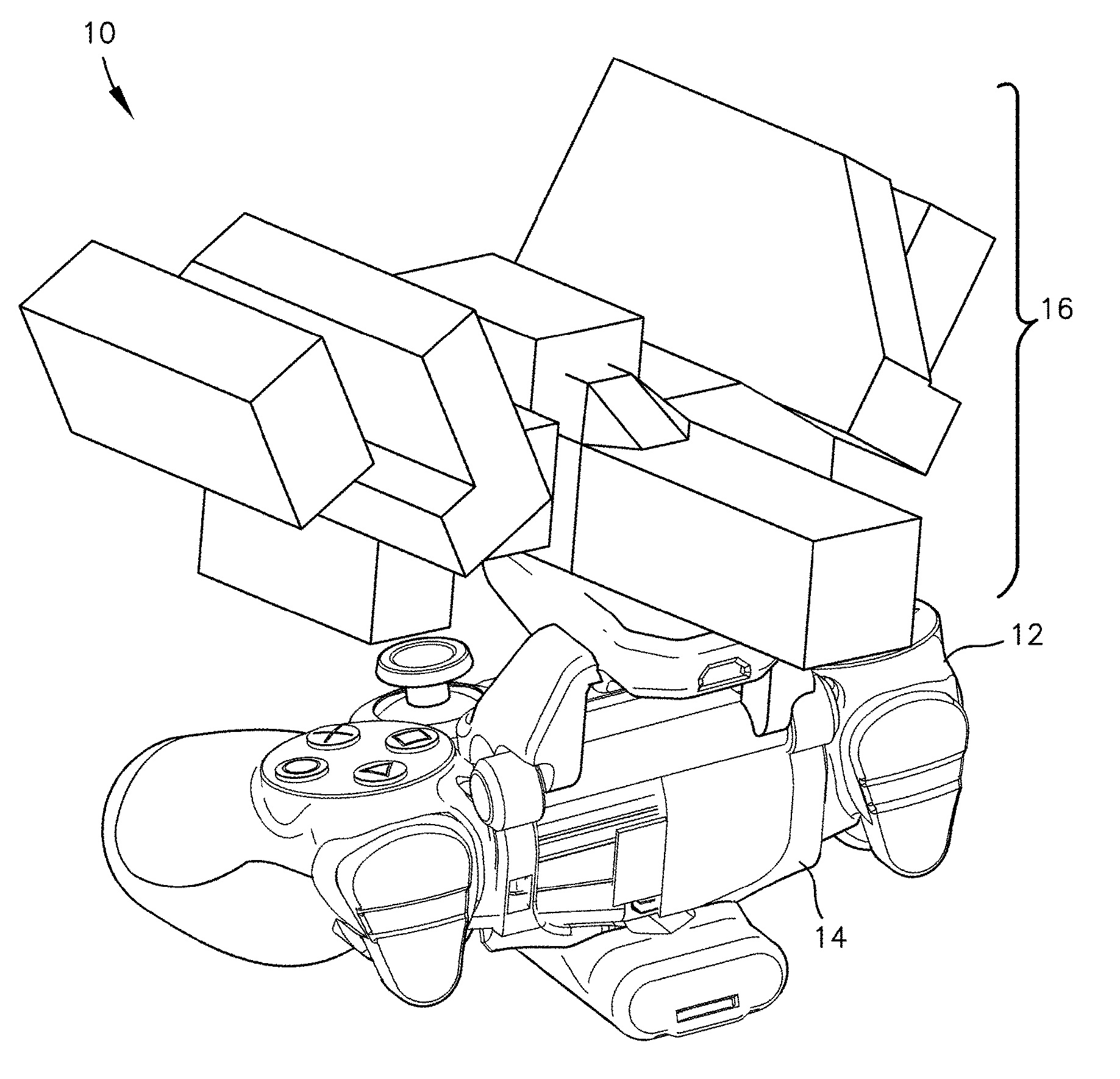
Turning now toFIG. 2, an oblique front view of a modular game accessory attached to a video game controller in accordance with embodiments of the invention is depicted. A complete assembly of controller, mount and modular game accessory may be referred to generally by reference numeral10. Game controller12may be a conventional game controller as used with a gaming console (such as, for example, a Sony® PlayStation® 4 or a Microsoft® Xbox™ One) or with a PC. Alternatively, depicted below inFIG. 11, it may be a dedicated controller designed to mount the modular game accessory. In the case where the modular game accessory is attached to a conventional game controller, mount14works to physically and/or electrically connect the modular game accessory, as described in greater detail below with respect toFIGS. 5 and 6.
Also depicted in the view ofFIG. 2is modular game accessory16. When a player is controlling a virtual game avatar using assembly10, modular game accessory16is securely attached to the controller in such a way that the player can easily take one hand off the controller and remove any of the modules of the modular game accessory16and exchange it for another module sitting on a table (for instance) in front of the player, or to entirely replace one modular game accessory with another modular game accessory. Modular game accessory16is described in greater detail below with respect toFIG. 3.
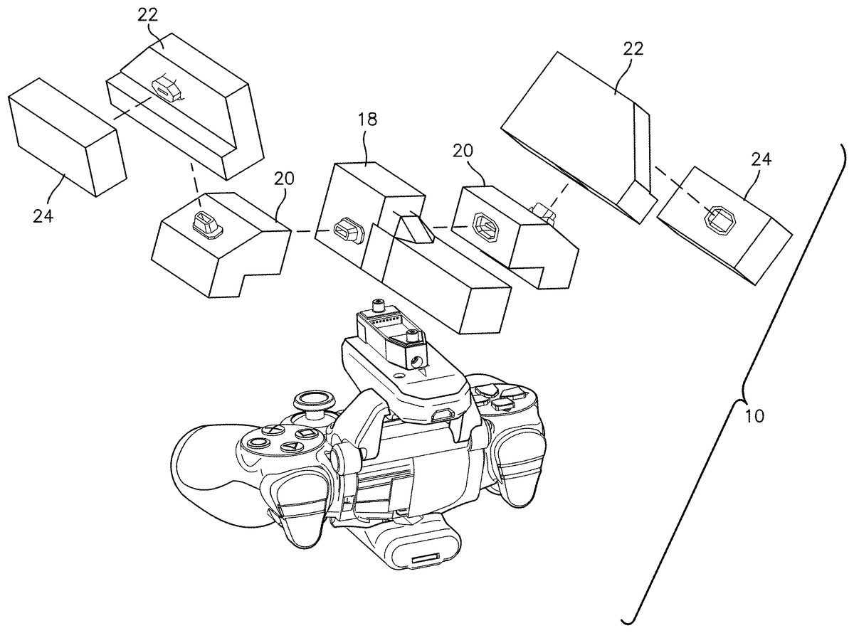
Turning now toFIG. 3, an exploded oblique front view of the modular game accessory as it attaches to the video game controller ofFIG. 2is depicted. As depicted, modular game accessory16includes base unit18. Other types of base unit are also envisioned as being within the scope of the invention. For example, instead of the depicted space ship hull, base unit18could instead represent a car chassis, a boat hull, an airplane hull or a tank hull. Base unit18may include one or more attachment points for physically connecting base unit18to mount14, such as slots, tabs, or other connectors. Connection may be via a friction fit or via positive locking points on base unit18or mount12. Base unit18may further include one or more electrical connectors for powering and/or communicatively coupling to base unit18and the other modules attached to it. In various embodiments, base unit18may represent different properties of the player's virtual avatar.
For example, if the player's virtual avatar is a space ship, then base unit18may represent the armor, cargo capacity, and/or crew complement of the virtual avatar. If instead the virtual avatar is a car or other land vehicle, then base unit18may instead represent the engines of the virtual avatar. In some embodiments, the base unit18may not itself represent any properties of the avatar but instead serve only as a platform for the modules that represent the avatar's properties. In some embodiments, each component of modular game accessory16affects a single, distinct property of the virtual avatar. In other embodiments, each component of modular game accessory16impacts a related set of properties (also known as a “constellation” of properties), and each property can be affected by more than one component.
Modular game accessory16, as depicted, further includes a set of add-on modules such as extension modules20and22, and leaf module24. For example, extension modules20may represent the wings attached to base unit18, extension modules22may be weapons racks attached to the wing modules and leaf modules24may be weapons pods connected directly to the weapon racks. In some embodiments, leaf modules can also connect directly to base unit18, as shown below with respect toFIGS. 8 and 9. In some embodiments, different base units representing different types of vehicle will have different module slots. For example, the space ship vehicles (as in base module18) has the depicted slots, while a car base unit would have slots for engine and wheel add-on modules. Similarly to how base unit18connects to mount14, these add-on modules may connect physically and/or electronically to base unit18. As is shown for leaf modules22, some add-on modules may connect to other add-on modules which are in turn connected to base unit18rather than connecting directly to base unit18themselves. In some embodiments, a standardized connection is used to attach add-on modules so that modules can be attached either directly or indirectly. Some extension modules may include connections for more than one other extension modules or leaf modules to be attached. Thus, the components of modular game accessory are connected in a logical tree topology, with mount14(or base hull unit18) corresponding to the root node, extension modules corresponding to branch nodes and leaf modules corresponding to leaf nodes. The tree topology may be two levels deep, three levels deep, four levels deep, or may be arbitrarily deep. In some embodiments, each module can only connect to a single other module, so that the modules form a chain topology. In some embodiments, properties of add-on modules may depend on their location in the topology, or the orientation in which they are attached. In such embodiment, the system can detect the location and orientation of each module within the logical connection topology. In this way, the game system can recognize and respond to how the player builds in addition to the modules they choose. Add-on modules are discussed further below with respect toFIGS. 9 and 10.
Turning now toFIG. 4, an oblique rear view of the modular game accessory attached to the video game controller is depicted. It can be seen in the depicted embodiment that mount14attaches to game controller12in such a way that the buttons and other controls of game controller are not obstructed and can still be used. Rather, as described above, modular game accessory16is kept securely attached to game controller12such that assembly10can be used as a unit, and such that the player can operate all of the buttons, control sticks, and other inputs of game controller12unimpeded. When game controller12includes gyroscopes, accelerometers, or other motion controls, the player may be able to control the virtual avatar by physically manipulating modular game accessory16using game controller12to which it is attached. In some embodiments, modular game accessory16may further include one or more indicators (such as, for example, LEDs) for displaying information about the components of modular game accessory. For example, the various add-on modules could have a multi-color LED to indicate damage taken by the corresponding virtual component.
Turning now toFIG. 5, a oblique rear view of the detached modular game accessory16, mount14for attaching it to the video game controller, and game controller12is depicted. As depicted mount,14attaches to game controller12by way of hinge25and latch26connecting upper mount28to lower mount26. Thus, to attach mount14to controller12, the player can disengage latch26and pivot lower mount30down to open mount14. Once game controller12is inserted into mount14, lower mount30can be pivoted back up and latch26reengaged to secure mount14around controller12.FIGS. 6 and 7below depict mount14as attached to controller12without modular game accessory16attached. Upper mount28further includes the above-described physical connectors32and (in some embodiments) electrical connector34for powering and communicating with modular game accessory16. In this way, different modular game accessories can be mounted on controller12, as described in greater detail below.
In some embodiments, modular game accessories such as modular game accessory16may be usable across multiple different video games. In other embodiments, modular game accessory may be useable outside the context of the video game. For example the modular game accessory may include buttons, speakers, lights, or make use of those on a connected controller to provide interaction when not connected to a computing device. For example, pushing buttons associated with various avatar abilities could cause corresponding sounds to play and/or lights to light up corresponding to those abilities on the modular game accessory. In another embodiment, the modular game accessory can include infrared transmitters and receivers to allow players to play a game of laser tag in physical space and, by swapping modules, choose special abilities and/or replace damaged components.
Turning now toFIG. 6, an oblique rear view of the mount for the modular game accessory as attached to the video game controller is depicted. This figure more clearly illustrates physical connectors32and electrical connectors34for coupling modular game accessory16to mount14and thereby to game controller12. In some embodiments, mount14may further include button36(or other control) for initializing, powering, or otherwise controlling modular game accessory16.
Turning now toFIG. 7, oblique bottom-rear view of the mount for the modular game accessory as attached to the video game controller is depicted. In some embodiments, mount14is powered from and communicates with game controller16via electrical connections. In other embodiments, mount14is self-powered and communicates wirelessly with game controller12(or with computer102directly). In some such embodiments, mount14may include battery door38giving access to replaceable batteries. In other embodiments, mount14may include rechargeable batteries and connectors for recharging them. In some embodiments featuring rechargeable batteries, mount14may connect to a recharging port for controller12and recharge via a pass-through connection.
Turning now toFIG. 8, a cross-sectional view of mount for the modular game accessory as attached to the video game controller, a hull unit suitable for attachment to the mount, and an add-on module connectable to the hull unit are depicted. In this figure, the clamshell nature of mount14as is it attached to game controller12can be seen. As depicted, latch26is closed, thereby securing mount14to game controller12. When latch26is disengaged, upper mount28and lower mount30can pivot around hinge25so that game controller12can be removed. In the depicted embodiment, battery door38can also be removed to replace or charge battery or batteries40used to power mount14.
Also shown is a cross-sectional view of modular game accessory16. In some embodiments, hull unit18includes a further add-on module slot corresponding to pilot42(or an analogous driver, as appropriate to the hull unit). Such a pilot or driver module may also be referred to more generally as a “character module.” In some embodiments, character module42may connect directly to mount14, and hull unit18connects on top of hull unit18. In some embodiments and some hull units, multiple character add-in slots may be available corresponding to different crew roles for a vehicle. For example, a tank hull unit may include character slots for a driver, a gunner, and a commander. As with other add-on modules, the character modules may affect various properties or constellations of properties of the virtual avatar. For example, the speed and maneuverability of the virtual avatar may be increased when a skilled pilot is added to modular game accessory16, while a skilled gunner may increase the accuracy of some or all of the attached weapons modules. As shown, add-on modules such as add-on leaf module24may also include electrical connectors44for communication with hull unit18, and ultimately with computer102. In this way, the effects of each add-on module can be provided by the add-on module itself, for example by an identifier stored in the module.
Turning now toFIG. 9, an oblique front view of a hull unit attachable to the mount ofFIGS. 6 and 7is depicted. As can be seen, base hull unit18includes one or more connectors46and48for connecting add-on modules such as extension module20for attaching to the sides of base unit18, leaf module22for attaching to extension modules20(or to the sides of base unit18directly), and leaf module24for attaching to the top of base unit18. In some embodiments, all of these connectors are standardized so that, for example, a particular add-on module can be used as a turret module, a wing module, or a wingtip pod module. In other embodiments, different physical connectors are used for each type of add-on module so that modules are dedicated to a particular type of port. Thus, leaf module24could only connect with connector46, and extension module20could only connect with connector48. Also depicted is cockpit50. As described above, in some embodiments, cockpit50can be opened to add a pilot character module42. In other embodiments, cockpit50is fixed, and characters are attached to mount14before base hull unit18is attached. In embodiments where connectors for the various modules are standardized, pilot character modules42may use a different type of connector to distinguish them from other types on add-on module.
Turning now toFIG. 10, a wing module (i.e., a logical extension module molded to look like the wing of a spaceship) connectable to the hull unit ofFIG. 9and weapons rack module (i.e., another logical extension module molded to looks like a wing-mounted weapons rack) connectable to the wing module is depicted. As can be seen, certain add on modules (such as, for example, the depicted module20) may themselves include additional expansion ports52for adding additional add-on modules such as extension module22. Of course, leaf modules such as leaf module24could also be connected directly to module20. Similarly, where modular game accessory16represents a tank, a turret module may include one or more expansion ports for weapon pods. Broadly, any collection of add-on modules connected directly or indirectly to mount14to make a modular game accessory16is contemplated as being within the scope of the invention. In particular, extension modules may connect to other extension modules in addition to base hull unit18directly, and may or may not have leaf modules attached to them.
In some embodiments, “blank” modules can also be provided for further customization, such that players can create a physical and virtual part with their preferred (physical and virtual) visual appearance and properties. Such modules may only include the electronics and connectors, such that a player can create their own physical housing with their desired appearance using, for example, a3D printer, a print-and-ship service, a packaged part kit, or any other method. In some such embodiments, the user may be able to specify the desired virtual appearance and properties using the video game, a dedicated application on the computer or video game console, or a dedicated programming cradle controlled by another computing device. The desired appearance and properties can be stored directly on the module or associated with a unique identifier for the blank module in an online data store, as discussed in additional detain below.
Turning now toFIG. 11, an oblique rear view of the modular game accessory attached to a dedicated controller with integrated mount is depicted. Here, modular game accessory16is attached to a dedicated controller54. This may be desirable if, for example, computer102being used with modular game accessory16is a PC and thus does not have a standard controller suitable for attaching mount14. Alternatively, dedicated controller may be usable in a single hand, unlike the two-handed operation of controller12. This allows the free hand to more quickly interchange modules for modular game accessory16. Alternatively, this may allow for the simultaneous use of two modular game accessories16by the player to control two virtual avatars in-game.
Turning now toFIG. 12, an oblique rear view of the modular game accessory as detached from the dedicated controller with integrated mount is depicted. As can be seen, in the depicted embodiment, a physical/electrical mounting point substantially similar to that of mount14is integrated into dedicated controller54. Thus modular game accessory16can be used with either dedicated controller54or with conventional game controller12in combination with mount14. In some embodiments, such as that depicted inFIG. 12, dedicated controller54includes only the subset of those controls of conventional game controller12used with the video game corresponding to modular game accessory16. As shown, the analog sticks, directional pad, touch pad, and several of the triggers have been omitted, while the buttons and gyroscopic controls have been retained. In other embodiments, dedicated controller54includes all of the controls and other functionality of conventional game controller12, and adds the attachment point and other functionality of mount14.
Operation of Embodiments of the Invention
Turning now toFIG. 13, a flowchart depicting a method of operating a modular game accessory with a video game in accordance with embodiments of the current invention is depicted and referred to generally by reference numeral1300. Initially, at step1302, an indication is received that a modular game accessory has been connected to the video game controller being used. In some embodiments, multiple players may each have their own game controller and corresponding modular game accessory and in-game virtual avatar. In such embodiments, the system can track which modular game accessory is attached to which game controller so that each player operates the appropriate virtual avatar in game. In some embodiments, the controller automatically detects when the modular game accessory is attached, replaced, or modified.
Next, at step1304, the system determines the type and/or identity of the base unit attached to the video game controller. In some embodiments and/or games, different vehicle types may be usable. For example, a particular game may have levels where a spaceship is required and levels where a ground vehicle such as a tank is required. Alternatively, another game might have levels where either an airplane or a ground vehicle can be used. In such embodiments, the player can choose which vehicle they wish to use for the level by attaching a modular game accessory with the corresponding type of base unit. As described above, types of base unit can include a space ship, a race car, a boat or submarine, a tank, a mech or other robot, or any other type of vehicle. Other, non-vehicular types of modular game accessory are also contemplated as being within the scope of the invention.
Within a given type of base unit, there may be many different models. For example, there may be many types of base unit (or hull) for a spaceship, such as (various types of) fighter, bomber, cruiser, carrier, dreadnought, cargo ship, etc. Similarly, where the base unit type corresponds to a tank, various historically accurate or fictional tank chassis can be chosen by the player and (as described below) customized via modular add-ons. Other types of base unit may also have corresponding models of base unit available.
Processing then proceeds to a step1306, where the system creates an in-game virtual avatar corresponding to the identified base unit is created. The in-game virtual avatar is broadly a digital representation of the player's character or vehicle which the player can control in order to play the video game. Broadly speaking, the in-game virtual avatar created may correspond virtually or in terms of capabilities to the modular game accessory that was attached at step1302. Thus, for example, if the player has attached a fighter hull as the base unit, then the virtual avatar created would be a small, agile, and armed space ship and if the player attaches an M60 chassis, then the digital avatar would have appearance and capabilities similar to an M60 main battle tank.
Next, at step1308, an add-on module attached to the base unit is identified. Broadly speaking, an add-on module is a physical representation of a component attachable to the base unit to add or modify the capabilities of the associated in-game virtual avatar. For example, where the base unit corresponds to a fighter model of space ship, add-on modules corresponding to various types of weapons (guns, lasers, missiles, etc.), wings or engines, fuel pods, or armor may be available. Similarly, for tanks, the add-on modules might correspond to main and off-axis weapons, treads, engines, and so on, while for a race car, the add-on modules might correspond to engine, transmission, tires, suspension, etc.
In some embodiments, the number of (physical or virtual) slots available for add-on modules may be limited to force the player to make trade offs between offensive and defensive capabilities, speed and range, and so forth. As described above, certain add-on modules may themselves include additional (physical and/or virtual) slots for other add-on modules. Thus, for example, the player might be offered the choice between a first set of wing modules offering high speed and maneuverability and a second set of wing modules offering lower speed and maneuverability but the ability to add additional weapons modules. As described above, in some embodiments, add-on modules may be restricted to particular physical slots on base unit. In other embodiments, add-ons are universal and can be inserted into any available slot.
In some embodiments, one or more special slots may be available for pilots, drivers, gunners, and other characters to further modify the capabilities of the in-game avatar. In some such embodiments, the character add-on modules may contribute variable capabilities to the in-game avatar depending on their experience level, which in turn depends on how much that particular character has been used in game. Thus, for example, a pilot which has been used for a large number of missions will have a higher level of skill (and therefore contribute more to the capabilities of the in-game avatar) than one which is being used for the first time. One of skill in the art will appreciate that the player may be given the option to customize the capabilities of the character modules when they are first used and as they are leveled up.
Once the add-on module has been identified, processing proceeds to step1310, where the in-game avatar created at step1306is modified to reflect the add-on module identified at step1308. The avatar can be modified both visually and in terms of its capabilities. For example, the base unit, add-on modules, and in-game avatar can be designed such that the in-game avatar resembles the assembled modular game accessory. The player's choice of character may also be visible through the cockpit of the in-game virtual avatar in some embodiments. Each add-on modules may also modify a capability or constellation of capabilities of the in-game avatar either positively or negatively. For example, a more powerful engine module may increase the speed of the in-game avatar, but also increase its weight and therefore decrease its maneuverability. As described above, each property of the in-game avatar may be modified by zero, one, or more than one add-on modules, and two add-on modules corresponding to the same slot may modify different properties, the same properties by different amounts, or the same properties by the same amount. In some embodiments, certain add-on modules have purely visual effects and do not modify any properties of the in-game avatar.
In some embodiments, add-on modules may contain storage readable and/or writable by the system. Thus, for example, the modules can store digital customizations chosen by the user, such as capability upgrades or visual customizations such as colors, patterns, apparel, skins, etc. In some embodiments, modules can store game progress. For example, in some embodiments, the in-game components corresponding to the add-on modules may be damaged over the course of the game. The add-on-modules may store this damage and/or visually reflect their status, and the damage may affect the capabilities modified by that add-on module. Thus, for example, a damaged engine may reduce the speed of the in-game avatar. In some embodiments, the player can remedy this problem either via in-game repairs (thus resetting the saved damage) or by physically replacing the “damaged” add-on modules with undamaged ones.
In this way, the player can use their customized avatar on another computing device or gaming console, even without a shared network resource, simply by attaching it to a connected game controller. As another advantage of this approach, a player could collect multiple copies of the same component, and store different customization and progress on each. In a variation of this embodiment, each module stores a globally unique identifier such as a serial number that can be used to access module properties in a networked data store. The gaming system can then connect to this server to read or write customization data for each module.
In some embodiments, each module includes a cryptographic verifier allowing the system to verify that the module is authentic and not counterfeit. For example, a tamper-resistant chip may store a private key for that device that can be verified when the modular game accessory is connected to a game console. In some such embodiments, this capability is combined with the unique identifier described above to ensure that the capabilities and modifications to each module are not tampered with.
Once the in-game avatar has been modified to reflect the add-on module identified at step1308, processing proceeds to decision1312where it is determined whether any additional add-on modules remain which have not yet been processed to modify the in-game avatar. If additional modules remain, processing returns to step13088. If all add-on modules have been processed, processing instead proceeds to step1314.
At step1314, command input is received from assembly10of game controller12, mount14and modular game accessory16(or assembly10of dedicated controller54and modular game accessory16). This input may correspond to the player's actuation of the controls of the video game controller, to accelerometer or gyroscope data indicating that the player is physically manipulating assembly10to control it, or from the player's actuation of controls on the mount or modular game accessory itself. In some embodiments, controller12or controller54includes accelerometers and/or gyroscopes for detecting gestural inputs. In other embodiments, the base unit includes the accelerometers and/or gyroscopes and passes the data to the controller to be communicated to computer102. In still other embodiments, the base unit communicates independently with computer102.
Next, at step1316, the in-game avatar is manipulated in accordance with the control input received at step1314. Thus, for example, if the player tilts the assembly left or right, the in-game avatar might steer left or right accordingly. If the player uses a particular button on the controller, the avatar might accelerate, and if the player actuates a trigger on the controller, the avatar might fire the weapons. In this way, the motion and actions of the in-game avatar reflect the motions and actions of the modular game accessory and controller, much like the appearance and capabilities of the in-game avatar reflect that of the modular game accessory. Processing then returns to step1314and steps1314and1316repeat until the player changes or modifies the modular game accessory (in which case processing restarts at step1302).
Many different arrangements of the various components depicted, as well as components not shown, are possible without departing from the scope of the claims below. Embodiments of the invention have been described with the intent to be illustrative rather than restrictive. Alternative embodiments will become apparent to readers of this disclosure after and because of reading it. Alternative means of implementing the aforementioned can be completed without departing from the scope of the claims below. Certain features and subcombinations are of utility and may be employed without reference to other features and subcombinations and are contemplated within the scope of the claims. Although the invention has been described with reference to the embodiments illustrated in the attached drawing figures, it is noted that equivalents may be employed and substitutions made herein without departing from the scope of the invention as recited in the claims.
Claims
- A system for playing a video game, comprising: a modular game accessory comprising: a base unit including a plurality of slots for attaching add-on modules;a plurality of add-on modules, each add-on module attachable to the base unit in a tree topology, wherein each of the plurality of add-on modules attached to the base unit is electrically coupled to the base unit to provide power to the add-on module and communication with the base unit;a mount for mounting the modular game accessory to a video game controller, wherein the video game controller includes motion controls;one or more computer-readable media storing computer-executable instructions that, when executed, allow a player to control an in-game avatar in the video game by physically manipulating modular game accessory such that a motion of the in-game avatar reflect a motion of the modular game accessory and controller, wherein the motion of the modular game accessory is transferred to the video game controller via the mount, wherein the transferred motion of the modular game accessory is detected by the motion controls of the video game controller, wherein the motion of the modular game accessory detected by the motion controls of the video game controller are communicated a video game console by the video game controller, wherein an appearance and one or more capabilities of the in-game avatar are determined by the modular game accessory connected to the video game controller while playing the video game, wherein each of the plurality of the add-on modules connected to the base unit affects at least one capability of the in-game avatar.
- The system of claim 1 , wherein the base unit represents a vehicle and the in-game avatar is a vehicle.
- The system of claim 2 , wherein the plurality of add-on modules includes one or more weapons modules.
- The system of claim 2 , wherein the plurality of add-on modules includes a character module.
- The system of claim 2 , wherein the plurality of add-on modules includes a leaf module.
- The system of claim 2 , wherein the vehicle is a space ship, and wherein the in-game avatar is a space ship.
- The system of claim 6 , wherein the plurality of add-on modules includes one or more wing modules.
- A method of using a modular game accessory to play a video game, comprising the steps of: receiving an indication that the modular game accessory comprising a base unit and a plurality of add-on-modules connected in a tree topology has been mounted on a video game controller, wherein the video came controller includes motion controls, wherein each of the plurality of add-on modules attached to the base unit is electrically coupled to the base unit to provide power to the add-on module and communication with the base unit;identifying the base unit of the modular game accessory;creating an in-game avatar in the video game corresponding to the identified base unit;identifying an add-on module of the plurality of add-on-modules attached to the base unit;modifying at least one characteristic of the in-game avatar based on the identified add-on module;receiving motion data from the video game controller indicating that a player has physically manipulated the modular game accessory, thereby also physically manipulating the video game controller on which the modular video game accessory is mounted and the motion controls thereof;processing the motion data as a command input from the motion controls of the video game controller;and manipulating the in-game avatar based on the received command input, such that one or more motions of the in-game avatar reflect one or more motions of the modular game accessory and controller.
- The method of claim 8 , further comprising the steps of: identifying an additional add-on module attached to the base unit;and modifying at least one additional characteristic of the in-game avatar based on the identified additional add-on module.
- The method of claim 8 , wherein the add-on module is a character module.
- The method of claim 8 , wherein the add-on module is a weapons module.
- The method of claim 8 , wherein the add-on module is a leaf module.
- The method of claim 8 , wherein the base unit corresponds to a space ship hull, and wherein the in-game avatar is a space ship.
- The method of claim 13 , wherein the add-on module is a wing module.
- The method of claim 14 , wherein a wingtip add-on module is connected to the wing module, and wherein the method further comprises the steps of: identifying the wingtip module as being attached to the wing module, and modifying an additional characteristic of the in-game avatar based on the identified wingtip module.
- A system for playing a video game, comprising: a modular game accessory comprising: a base unit including a plurality of slots for attaching add-on modules;a plurality of add-on modules, each add-on module attachable to the base unit in a tree topology, wherein each of the plurality of add-on modules attached to the base unit is electrically coupled to the base unit to provide power to the add-on module and communication with the base unit;a mount for mounting the modular game accessory to a video game controller, wherein the video game controller includes motion controls;one or more computer-readable media storing computer-executable instructions that, when executed, perform a method of using the modular game accessory to play the video game, comprising the steps of: receiving an indication that the modular game accessory has been mounted on the video game controller;identifying the base unit of the modular game accessory;creating an in-game avatar in the video game corresponding to the identified base unit;identifying an add-on module of the plurality of add-on modules that is attached to the base unit;modifying at least one characteristic of the in-game avatar based on the identified add-on module;receiving motion data from the video game controller indicating that a player has physically manipulated the modular game accessory, thereby also physically manipulating the video game controller on which the modular video game accessory is mounted and the motion controls thereof;processing the motion data as a command input from the motion controls of the video game controller;and manipulating the in-game avatar based on the received command input, such that one or more motions of the in-game avatar reflect one or more motions of the modular game accessory and controller.
- The system of claim 16 , wherein the method further comprises the steps of: identifying an additional add-on module of the plurality of add-on modules attached to the base unit;and modifying at least one additional characteristic of the in-game avatar based on the identified additional add-on module.
- The system of claim 16 , wherein the base unit corresponds to a space ship hull, and wherein the in-game avatar is a space ship.
- The system of claim 16 , wherein the add-on module is a character module.
Disclaimer: Data collected from the USPTO and may be malformed, incomplete, and/or otherwise inaccurate.