U.S. Pat. No. 10,286,307
GAME CONTROLLER WITH REMOVABLE FACETED FINGER PAD
AssigneeMICROSOFT TECHNOLOGY LICENSING, LLC
Issue DateFebruary 22, 2018
U.S. Patent no. 10,286,307: Game controller with removable faceted finger pad
U.S. Patent no. 10,286,307: Game controller with removable faceted finger pad
Issued May 14, 2019, to Microsoft Technology Licensing, LLC
Priority Date June 4, 2015
Summary:
U.S. Patent No. 10,286,307 (the ‘307 Patent) relates to game controllers. A game controller may be used to control an object or move a character in a video game. Different games may require different types of controls for optimal gameplay. The ‘307 Patent describes a finger pad for a game controller that can be easily replaced with different types of control pads depending on the game being played. The game controller is customizable and includes one or more finger manipulatable controls that can be swapped out without using tools. Some controls may be better used in a fighting game as opposed to a shooting game. Different players may also prefer different configurations. The ‘307 Patent increases the accessibility of video games.
Abstract:
A finger pad for a game controller includes a first side and a second side opposite the first side. The first side includes a finger interface. The finger interfaces includes a plurality of planar facets. The planar facets are sized and shaped for manual manipulation by a finger. The second side includes a mounting interface.
Illustrative Claim:
1. A removable finger pad for a game controller, the removable finger pad comprising: a first side including a finger interface, the finger interface including: a center planar facet having an up edge parallel to a left-right axis, a right edge parallel to an up-down axis, a down edge parallel to the left-right axis, and a left edge parallel to the up-down axis, wherein the left-right axis is perpendicular to the up-down axis; a cardinal-up planar facet sharing the up edge with the center planar facet and extending at a ramp angle from the center planar facet; a cardinal-right planar facet sharing the right edge with the center planar facet and extending at the ramp angle from the center planar facet; a cardinal-down planar facet sharing the down edge with the center planar facet and extending at the ramp angle from the center planar facet; and a cardinal-left planar facet sharing the left edge with the center planar facet and extending at the ramp angle from the center planar facet; and a second side opposite the first side, the second side including a mounting interface configured to mate with a mounting platform of the game controller to removably affix the removable finger pad to the mounting platform.
Illustrative Figure
Abstract
A finger pad for a game controller includes a first side and a second side opposite the first side. The first side includes a finger interface. The finger interfaces includes a plurality of planar facets. The planar facets are sized and shaped for manual manipulation by a finger. The second side includes a mounting interface.
Description
DETAILED DESCRIPTION User input control devices, such as game controllers, may be shaped/sized to fit an average hand size of a population of users. Likewise, finger-manipulatable controls (e.g., push buttons, triggers, joysticks, directional pads) that are integral to a game controller have traditionally been designed according to a “one size fits all” approach. However, different users may have different preferences on the shape, size, color, texture, or other attributes of such controls. The present disclosure is directed to a customizable game controller that includes one or more finger manipulatable controls that can be swapped out in a tool-free manner. For example, such a configuration may facilitate the use of differently configured removable controller accessories that are customized for particular types of video games to be quickly swapped on the game controller when switching between playing different video games. In another example, such a configuration may facilitate the use of differently configured removable controller accessories that are preferred by different players to be quickly swapped on the game controller when the game controller is used by the different players. FIGS. 1 and 2show an example user input control device in the form of a game controller100. The game controller100may be configured to translate user input into control signals that are provided to a computing device, such as a gaming console. The control signals may be mapped to commands to control a video game or perform other operations. For example, the game controller100may be configured to send control signals via a wired or wireless connection with a computing device. The game controller100includes a plurality of controls102configured to generate different control signals responsive to finger manipulation. One or more of the plurality of controls102may include a removable finger pad114. The removable finger pad114may be one of a plurality of differently configured removable controller ...
DETAILED DESCRIPTION
User input control devices, such as game controllers, may be shaped/sized to fit an average hand size of a population of users. Likewise, finger-manipulatable controls (e.g., push buttons, triggers, joysticks, directional pads) that are integral to a game controller have traditionally been designed according to a “one size fits all” approach. However, different users may have different preferences on the shape, size, color, texture, or other attributes of such controls.
The present disclosure is directed to a customizable game controller that includes one or more finger manipulatable controls that can be swapped out in a tool-free manner. For example, such a configuration may facilitate the use of differently configured removable controller accessories that are customized for particular types of video games to be quickly swapped on the game controller when switching between playing different video games. In another example, such a configuration may facilitate the use of differently configured removable controller accessories that are preferred by different players to be quickly swapped on the game controller when the game controller is used by the different players.
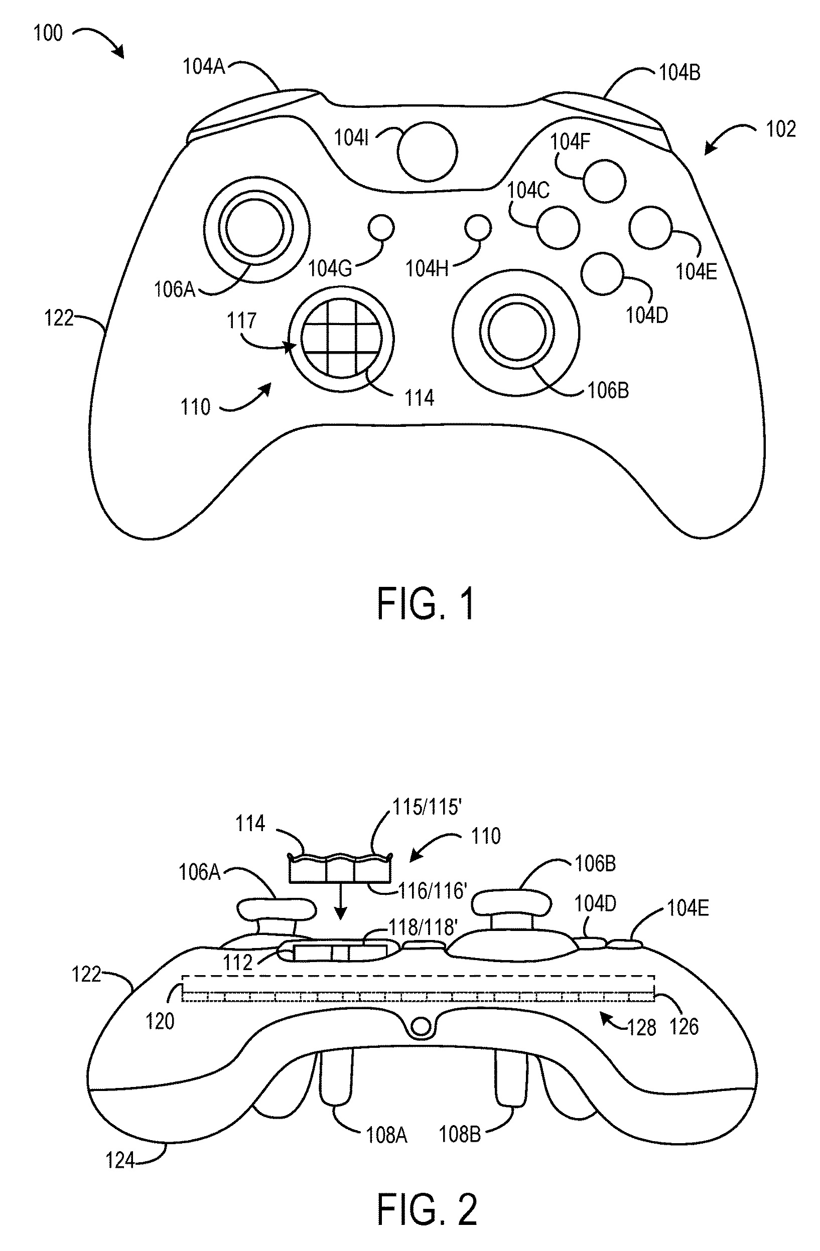
FIGS. 1 and 2show an example user input control device in the form of a game controller100. The game controller100may be configured to translate user input into control signals that are provided to a computing device, such as a gaming console. The control signals may be mapped to commands to control a video game or perform other operations. For example, the game controller100may be configured to send control signals via a wired or wireless connection with a computing device.
The game controller100includes a plurality of controls102configured to generate different control signals responsive to finger manipulation. One or more of the plurality of controls102may include a removable finger pad114. The removable finger pad114may be one of a plurality of differently configured removable controller accessories removably affixable to the game controller100. For example, various differently configured removable controller accessories may have different sizes, shapes, and/or textured surfaces that are preferred by different users or may be suited for particular gaming or other purposes.
In the depicted implementation, the plurality of controls102includes a plurality of action buttons104(e.g.,104A,104B,104C,104D,104E,104F,104G,104H, and104I), a plurality of joysticks106(e.g., a left joystick106A and a right joystick106B), a plurality of triggers108(e.g., a left trigger108A and a right trigger108B), and a directional pad110. The plurality of controls102may be coupled to a frame120(shown in more detail inFIG. 17). The frame120may be contained collectively within an upper housing portion122and a lower housing portion124of the game controller100. In other words, the upper housing portion122and the lower housing portion124may cooperate to form a housing that contains at least a portion of each of the plurality of controls102that are coupled to the frame120.
A printed circuit board126may be coupled to the frame120. The printed circuit board126may include a plurality of electronic input sensors128. Each electronic input sensor may be configured to generate an activate control signal responsive to interaction with a corresponding control. Non-limiting examples of electronic input sensors may include dome switches, tactile switches, Hall Effect sensors, potentiometers, and other electronic sensing components. Any suitable sensor may be implemented in the game controller100. In some implementations, two or more printed circuit boards may be used.
The game controller100may include any number of controls, any type of controls, any number of electronic input sensors, and any type of electronic input sensors without departing from the scope of this disclosure.
Each of the action buttons104may be configured to activate a corresponding electronic input sensor128to generate an activate control signal responsive to being depressed (e.g., via finger manipulation). For example, each control signal associated with an action button may be mapped to a video game operation. Different video games may have different mappings of control signals to operations. In some cases, each action button may be mapped to a different operation. In other cases, two action buttons may be mapped to a same operation.
Each of the joysticks106may be configured to provide two-dimensional input that is based on a position of the joystick in relation to a default “center” position. For example, the joysticks may interact with electronic input sensors in the form of potentiometers that use continuous electrical activity to provide an analog input control signal.
Each of the triggers108may be configured to provide a variable control signal based on a position of the trigger relative to a default position. For example, as a trigger is pulled farther away from the default position a characteristic of the generated control signal may increase in magnitude.
In the depicted implementation, the directional pad110is the only control on the game controller100that is configured to interface with a plurality of differently configured removable controller accessories such that a selected removable controller accessory may be removably affixed to the game controller100. In particular, the directional pad110includes a mounting platform112configured to interface with a selected removable controller accessory in the form of a removable finger pad114. The mounting platform112may include a topside118including an accessory-retention interface118′ configured to interface with a mounting interface116′ of the removable finger pad114.
As such, the directional pad110includes the mounting platform112and the removable finger pad114when the removable finger pad114is removably affixed to the mounting platform112.
In the illustrated example, the removable finger pad114includes a topside115that includes a finger interface115′. The finger interface115′ includes a plurality of planar facets117sized and shaped for manual manipulation by a finger. In particular, each planar facet may include a plurality of edges that define a flat surface of that planar facet. The plurality of planar facets117may be arranged to facilitate movement of the finger pad114in specific directions corresponding to the different planar facets. For example, the plurality of planar facets117include a center planar facet having four edges and four cardinal facets each aligned with a different edge of the center planar facet. The four cardinal planar facets may facilitate movement of the finger pad114in the four cardinal directions (e.g., up, down, left, right). Further, the plurality of planar facets117include four diagonal planar facets that are each positioned between a different pair of cardinal planar facets. Each diagonal planar facet may extend outward from a corner of the center planar facet. The four diagonal planar facets may facilitate movement of the finger pad114in four diagonal directions (e.g., up-right, down-right, down-left, up-left).
The center planar facet may be oriented to have a level surface that does not slope in any direction. Further, each of the four cardinal planar facets and each of the four diagonal planar facets may ramp upward from the center planar facet to a perimeter edge of the finger interface115′. Such a configuration may form a faceted bowl. Moreover, the angle of each of the plurality of planar facets117may allow a user to easily recognize each different direction in which the finger pad114may be depressed. Furthermore, since each of the plurality of planar facets117has a different orientation, a user may easily recognize a boundary between different facets without any additional textural indicators (e.g., ridges, bumps, depressions, or other barriers). Correspondingly, the relatively smooth surface collectively created by the plurality of planar facets117may allow for fluid thumb movements between the different planar facets without interference from any textural indicators. Accordingly, a user may quickly transition between pressing different directions on the finger pad114.
Note that the planar faceted configuration is merely one non-limiting example, and the finger interface115′ may include any suitable surface, feature, shape, and/or structure configured to be touched and/or manually manipulated by a finger to provide user input. Further note that, in some implementations, the finger pad114including the plurality of planar facets117may be integral to the directional pad110such that the finger pad114is not removable. In other words, the directional pad110may include the plurality of planar facets117.
The removable finger pad114may include an underside116that is opposite the topside115. The underside116may include the mounting interface116′ The mounting interface116′ may include any suitable surface, feature, shape, and/or structure configured to selectively mate with the mounting platform112to removably affix the removable finger pad114to the game controller100. For example, the mounting interface116′ of the removable finger pad114may have a shape that complements a shape of an accessory-retention interface118′ of the mounting platform112. Such corresponding interfaces may aid the removable finger pad114in aligning with the mounting platform112to removably affix the removable finger pad114to the game controller100.
Furthermore, the mounting platform112may include one or more accessory-retention features (examples of which are shown at least atFIGS. 13-14 and 14-19) configured to removably affix various removable controller accessories to the game controller100without the use of any tools. Such accessory-retention features may allow for differently configured removable controller accessories to be quickly and easily interchanged without the use of tools.
The directional pad110may be configured to reside in a default posture when no touch force is applied to the directional pad110. In the default posture, the directional pad110does not cause any of the plurality of electronic input sensors128to generate an activate control signal indicative of touch input. Further, the directional pad110may be configured to move from the default posture to a selected activation posture responsive to a touch force being applied to the directional pad110. The selected activation posture may be one of a plurality of different activation postures that each generate a different activate control signal or combination of activate control signals by interfacing with different electronic input sensors.
Note that the activation signal indicative of touch input produced in the selected activation posture may be any signal that differs from a signal or lack thereof produced in the default posture. For example, in some implementations, the activation signal may correspond to a supply voltage (e.g., VDD) of the game controller100and the signal produced in the default state may correspond to a relative ground. (e.g., 0). In other implementations, the activation signal may correspond to a relative ground and the signal produced in the default state may correspond to the supply voltage of the game controller100.
In the depicted implementation, the directional pad110is depressible in four different directions (e.g., up, down, left, and right) to interface with different electronic input sensors that generate different activate control signals. In some implementations, the four different directions may correspond to four different activation postures that generate four different activate control signals to provide four-way directional input. In some implementations, combinations of activate control signals corresponding to pressing the directional pad110in two directions (e.g., up and left) at one time may be interpreted as additional activation postures corresponding to diagonals in between the four directions to provide eight-way directional input. In some implementations, the directional pad110may include a number of directions different than four or eight. For example, the directional pad110may include two or more different directions.
Note that the mounting platform112may be further configured such that when a removable controller accessory is not affixed to the mounting platform112, a touch force may be applied directly to the mounting platform112. The mounting platform112may be configured to translate the touch force into movement of the mounting platform112that applies an activation force to one or more electronic input sensors to generate one or more different control signals. In other words, the mounting platform112may function as a directional pad itself when a removable controller accessory is not affixed to the mounting platform112. In one example, an activation force may include an amount of force sufficient to actuate a dome switch. The activation force may be any suitable amount of force to activate an electronic input sensor.
Although the mounting platform112may translate a touch force to an activation force, the mounting platform112may otherwise differ from a traditional directional pad. For example, the mounting platform112may be recessed from a surface of the upper housing portion122of the game controller100in order to accommodate a thickness of the removable finger pad114. As such, the removable finger pad114will not excessively protrude from the mounting platform112and interfere with operation of other controls (e.g., joystick106A) of the game controller100. Further, the topside118of the mounting platform112may have abrupt edges that are configured to mate with the finger pad114. In contrast, traditional directional pads may have edges and surfaces that are contoured to comfortably accommodate a user's thumb.
In the depicted implementation, the directional pad110is the only control of the plurality of controls102on the game controller100that is configured to removably affix differently configured removable controller accessories to the game controller100. In other implementations, the game controller100may include more than one control that is configured to removably affix differently configured removable controller accessories to the game controller100. Further, in some implementations, the game controller100may include different types of controls other than the directional pad110that are configured to removably affix differently configured removable controller accessories to the game controller. For example, one or more of the joysticks, action buttons, or triggers may be configured to removably affix differently configured removable controller accessories to the game controller100.
In some implementations where two different controls are configured to removably affix removable controller accessories to the game controller100, each such control may be configured to interact with a different group of removable controller accessories. In particular, the different removable controller accessories in a given group may have a same mounting interface that is configured to be removably affixed to a particular control. In other words, a selected removable controller accessory may only be compatible with one of the two controls. In other implementations, where two different controls are configured to removably affix removable controller accessories to the game controller100, both controls may be configured in the same manner such that a selected removable controller accessory may be compatible to be removably affixable to both controls.
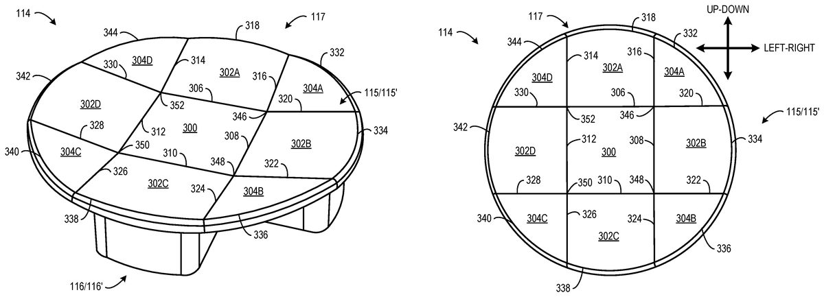
FIGS. 3-5show the finger pad114having a finger interface115′ including a plurality of planar facets117that collectively form a faceted bowl shape. In particular, the finger interface115′ includes a center planar facet300bordered by four straight edge segments. In particular, center planar facet300has an up edge306, a right edge308, a down edge310, and a left edge312that collectively define and border a surface of the center planar facet300. The up edge306and the down edge310may be parallel to a left-right axis (shown inFIG. 5). The right edge308and the left edge312may be parallel to an up-down axis (shown inFIG. 5). As shown inFIG. 5, the left-right axis is perpendicular to the up-down axis. The up edge306and the right edge308meet at an up-right corner346. The right edge308and the down edge310meet at a down-right corner348. The down edge310and the left edge312meet at a down-left corner350. The left edge312and the up edge306meet at an up-left corner352. Each corner forms a right angle. In some implementations, the corners may be rounded corners. In such implementations, the center planar facet may be bordered by the up edge segment, the right edge segment, the down edge segment, the left edge segment, and the rounded corners.
A plurality of cardinal planar facets302neighbor the center planar facet300in the four cardinal directions (e.g., up, down, left, right). In particular, the plurality of cardinal planar facets302include a cardinal-up planar facet302A, a cardinal-right planar facet302B, a cardinal-down planar facet302C, and a cardinal-left planar facet302D. The cardinal-up planar facet302A is bordered by the up edge306, an up-left ramp edge314, an up-right ramp edge316, and an up-perimeter edge318. The up-left ramp edge314and the up-right ramp edge316are parallel to the up-down axis. The cardinal-up planar facet302A is said to neighbor the center planar facet300, because the cardinal-up planar facet302A shares the up edge306with the center planar facet300.
The cardinal-right planar facet302B is bordered by the right edge308, a right-up ramp edge320, a right-down ramp edge322, and a right-perimeter edge334. The right-up ramp edge320and the right-down ramp edge322are parallel to the left-right axis. The cardinal-right planar facet302B is said to neighbor the center planar facet300, because the cardinal-right planar facet302B shares the right edge308with the center planar facet300.
The cardinal-down planar facet302C is bordered by the down edge310, a down-right ramp edge324, a down-left ramp edge326, and a down-perimeter edge338. The down-right ramp edge324and the down-left ramp edge326are parallel to the up-down axis. The cardinal-down planar facet302C is said to neighbor the center planar facet300, because the cardinal-down planar facet302C shares the down edge310with the center planar facet300.
The cardinal-left planar facet302D is bordered by the left edge312, a left-down ramp edge328, a left-up ramp edge330, and a left-perimeter edge342. The left-down ramp edge328and the left-up ramp edge330are parallel to the left-right axis. The cardinal-left planar facet302D is said to neighbor the center planar facet300, because the cardinal-left planar facet302D shares the left edge312with the center planar facet300.
Furthermore, a plurality of diagonal planar facets304neighbor the center planar facet300. In particular, each diagonal planar facet304is positioned between a different pair of cardinal planar facets of the plurality of cardinal planar facets302. A diagonal up-right planar facet304A is bordered by the up-right ramp edge316, the right-up ramp edge320, and an up-right perimeter edge332. The diagonal up-right planar facet304A shares the up-right ramp edge316with the cardinal-up planar facet302A. The diagonal up-right planar facet304A shares the right-up ramp edge320with the cardinal-right planar facet302B. The diagonal up-right planar facet304A is said to neighbor the center planar facet300, because the diagonal up-right planar facet304A and the center planar facet300meet at the up-right corner346.
A diagonal down-right planar facet304B is bordered by the right-down ramp edge322, the down-right ramp edge324, and a down-right perimeter edge336. The diagonal down-right planar facet304B shares the right-down ramp edge322with the cardinal-right planar facet302B. The diagonal down-right planar facet304B shares the down-right ramp edge324with the cardinal-down planar facet302C. The diagonal down-right planar facet304B is said to neighbor the center planar facet300, because the diagonal down-right planar facet304B and the center planar facet300meet at the down-right corner348.
A diagonal down-left planar facet304C is bordered by the down-left ramp edge326, the left-down ramp edge328, and a down-left perimeter edge340. The diagonal down-left planar facet304C shares the down-left ramp edge326with the cardinal-down planar facet302C. The diagonal down-left planar facet304C shares the left-down ramp edge328with the cardinal-left planar facet302D. The diagonal down-left planar facet304C is said to neighbor the center planar facet300, because the diagonal up-right planar facet304A and the center planar facet300meet at the down-left corner350.
A diagonal up-left planar facet304D is bordered by the left-up ramp edge330, the up-left ramp edge314, and an up-left perimeter edge344. The diagonal up-left planar facet304D shares the left-up ramp edge330with the cardinal-left planar facet302D. The diagonal up-left planar facet304D shares the up-left ramp edge314with the cardinal-up planar facet302A. The diagonal up-left planar facet304A is said to neighbor the center planar facet300, because the diagonal up-left planar facet304D and the center planar facet300meet at the up-left corner352.
In the illustrated implementation, the center planar facet300has a flat and level orientation. Further, each ramp edge (e.g.,314,316,320,322,324,326,328,330) extends at a ramp angle Θ (shown inFIG. 4) from the center planar facet300to a corresponding perimeter edge (e.g.,318,332,334,336,338,340,342,344). As such, the up-perimeter edge318is higher than the up edge306, the right-perimeter edge334is higher than the right edge308, the down-perimeter edge338is higher than the down edge310, and the left-perimeter edge342is higher than the left edge312. Likewise, the up-right perimeter edge332is higher than the up-right corner346, the down-right perimeter edge336is higher than the down-right corner348, the down-left perimeter edge340is higher than the down-right corner350, and the up-left perimeter edge344is higher than the up-left corner352. In other words, each of the plurality of cardinal planar facets302and each of the plurality of diagonal planar facets304ramp upward from the center planar facet300.
Further, each perimeter edge (e.g.,318,332,334,336,338,340,342,344) is rounded such that each diagonal planar facet304has a sector shape and each cardinal planar facet302has a rectangular shape with a rounded outer edge. Such a configuration creates a faceted bowl or concave shape with the center planar facet300being positioned at a nadir of the bowl. Such a configuration may bias a position of a thumb placed on the finger interface115′ toward the center of the finger interface115′, while also allowing the thumb to easily detect and move to any of the plurality of planar facets117corresponding to the different directions on the finger pad114.
The finger pad114may provide eight-way directional user input control. Although other finger pads may include any number of planar facets having any suitable size and/or shape without departing from the scope of the present disclosure. In some implementations, the cardinal planar facets all may be the same size. In other implementations, different cardinal facets may have different sizes and/or shapes. In one example, the cardinal planar facets may extend further outward than the diagonal planar facets, such that the finger interface115′ may have a shape of a cross overlaid on and extending from a circle or diamond. In another example, the diagonal planar facets may extend further outward than the cardinal planar facets. Further, in some implementations, the diagonal planar facets may have differently shaped outer edges than the cardinal planar facets, and vice versa. For example, the cardinal planar facets may have outer edge that are straight, and the diagonal planar facets may have outer edges that are rounded.
Furthermore, each ramp edge may be oriented at any suitable ramp angle without departing from the scope of the present disclosure. For example, the ramp angle Θ may be 10°, 15°, 30°, 45° or another angle. By virtue of the geometry, the cardinal planar facets ramp at the same angle as the ramp angles of adjacent ramp edges, while the diagonal planar facets will ramp at a lesser angle (as measured along a line that bisects the diagonal planar facet). Moreover, different swappable finger pads may be configured with different ramp angles such that the faceted bowl shape may be deeper or shallower to suit preferences of different users. In some implementations, different cardinal and/or diagonal planar facets may have different ramp angles.
Further still, the finger pad114may be any suitable height. Moreover, different swappable finger pads may be configured with different heights to suit preferences of different users.
FIGS. 6-8show another example finger pad600having topside602and an underside601opposite the topside602. The underside601includes a mounting interface601′. The topside602includes a finger interface602′ including a plurality of planar facets604that collectively form a cross shape. The finger pad600is configured to provide four-way directional input, because the finger pad600does not include any diagonal planar facets. In particular, the finger interface602′ includes a center planar facet606having an up edge610, a right edge612, a down edge614, and a left edge616that collectively define a surface of the center planar facet606. The up edge610and the down edge614may be parallel to a left-right axis (shown inFIG. 8). The right edge612and the left edge616may be parallel to an up-down axis (shown inFIG. 8).
A plurality of cardinal planar facets608neighbor the center planar facet606in the four cardinal directions (e.g., up, down, left, right). In particular, the plurality of cardinal planar facets608include a cardinal-up planar facet608A, a cardinal-right planar facet608B, a cardinal-down planar facet608C, and a cardinal-left planar facet608D. The cardinal-up planar facet608A is bordered by the up edge610, an up-left ramp edge618, an up-right ramp edge620, and an up-perimeter edge622. The up-left ramp edge618and the up-right ramp edge620are parallel to the up-down axis. The cardinal-up planar facet608A is said to neighbor the center planar facet606, because the cardinal-up planar facet608A shares the up edge610with the center planar facet606.
The cardinal-right planar facet608B is bordered by the right edge612, a right-up ramp edge624, a right-down ramp edge626, and a right-perimeter edge628. The right-up ramp edge624and the right-down ramp edge626are parallel to the left-right axis. The cardinal-right planar facet608B is said to neighbor the center planar facet606, because the cardinal-right planar facet608B shares the right edge612with the center planar facet606.
The cardinal-down planar facet608C is bordered by the down edge614, a down-right ramp edge630, a down-left ramp edge632, and a down-perimeter edge634. The down-right ramp edge630and the down-left ramp edge632are parallel to the up-down axis. The cardinal-down planar facet608C is said to neighbor the center planar facet606, because the cardinal-down planar facet608C shares the down edge614with the center planar facet606.
The cardinal-left planar facet608D is bordered by the left edge616, a left-down ramp edge636, a left-up ramp edge638, and a left-perimeter edge640. The left-down ramp edge636and the left-up ramp edge638are parallel to the left-right axis. The cardinal-left planar facet608D is said to neighbor the center planar facet606, because the cardinal-left planar facet608D shares the left edge616with the center planar facet606.
In the illustrated implementation, the center planar facet606has a flat and level orientation. Further, each ramp edge (e.g.,618,620,624,626,630,632,636,640) extends at a ramp angle Θ (shown inFIG. 7) from the center planar facet606to a corresponding perimeter edge (e.g.,622,628,634,640). As such, the up-perimeter edge622is higher than the up edge610, the right-perimeter edge628is higher than the right edge612, the down-perimeter edge634is higher than the down edge614, and the left-perimeter edge640is higher than the left edge616. In other words, each of the plurality of cardinal planar facets604ramp upward from the center planar facet606. Further, in this implementation, the ramp edges (e.g.,618,620,624,626,630,632,636,640) are also perimeter edges, because the finger pad600does not include any diagonal planar facets. Rather, a gap is formed diagonally between each cardinal planar facet and a neighboring cardinal planar facet of the plurality of cardinal planar facets604.
Such a configuration creates a faceted concave shape with the center planar facet606being positioned at a nadir of the faceted concave shape. Such a configuration may bias a position of a thumb placed on the finger interface602′ toward the center of the finger interface602′, while also allowing the thumb to easily detect and move to any of the plurality of planar facets604corresponding to the different directions on the finger pad600.
FIGS. 9-10show another example finger pad900having topside902and an underside901opposite the topside902. The underside901includes a mounting interface901′. The topside902includes a finger interface902′ including a plurality of planar facets904that collectively form a concave octagonal shape. The finger pad900is configured to provide eight-way directional input in the same manner as the finger pad114shown inFIGS. 3-5. The finger pad900includes a center planar facet906, a plurality of cardinal planar facets910(e.g.,908A,908B,908C,908D), and a plurality of diagonal planar facets910(e.g.,910A,910B,910C,910D). The plurality of planar facets904interconnect in the same manner as the plurality of facets117of the finger pad114shown inFIGS. 3-5, and for purposes of brevity such interconnections will be discussed no further.
In the illustrated implementation, each of the plurality of planar facets include a perimeter edge that is straight. In particular, an up-perimeter edge912, an up-right-perimeter edge914, a right-perimeter right edge916, a down-right-perimeter edge918, a down-perimeter edge920, a down-left-perimeter edge922, a left-perimeter edge924, and an up-left-perimeter edge926are all straight. These straight edges collective form an octagonal shaped perimeter of the finger interface902. Further, the straight perimeter edges of the cardinal planar facets908may cause the cardinal planar facets to be rectangular. Further, the straight perimeter edges of the diagonal planar facets910may cause the diagonal planar facets to be triangular.
In the illustrated implementation, perimeter corners created by adjoining straight perimeter edges may provide more pronounced tactile feedback of facet boundaries relative to the circular dish shape of the finger pad114that may be desirable to some users. Moreover, such an implementation may have a smaller footprint relative to the finger pad114that may be applicable for smaller game controllers with tighter spacing between controls.
In still other implementations, the cardinal planar facets and/or the diagonal planar facets may have differently-shaped perimeter edges. For example, perimeter edges may be arced toward a center planar facet to further pronounce perimeter corners between cardinal facets and diagonal facets (or gaps).
FIGS. 11 and 12show interfacing sides of the mounting platform112and the removable finger pad114. In particular,FIG. 11shows the topside118(e.g., the accessory-retention interface) of the mounting platform112. The mounting platform112includes a cross-shaped protrusion1100that extends from a base piece1102. The cross-shaped protrusion includes a plurality of branches1104(e.g.,1104A,1104B,1104C,1104D) that extend in different directions (e.g., up, down, left, right). In the depicted implementation, each of the plurality of branches1104have the same length. In other implementations, different branches of the cross-shaped protrusion1100may have different lengths. The mounting platform112may include any suitable number of branches that extend in any suitable direction(s).
Furthermore, the base piece1102includes a plurality of mounting tabs1106(e.g.,1106A,1106B,1106C) that are configured to interact with the frame120(shown in more detail inFIG. 17) to couple the mounting platform112to the game controller100. When the mounting platform112is coupled to the frame120, the plurality of mounting tabs1106may be inserted into corresponding mounting brackets902(shown inFIG. 17) of the frame120to inhibit the mounting platform112from twisting in the game controller100. In some implementations, the mounting platform112may include an accessory-retention interface118having a non-branch shape. For example, the accessory-retention interface118may include a circle, triangle, square, star, or other shape.
FIG. 12shows the underside116of the removable finger pad114. The underside116may include a mounting interface116′ configured to have a shape that complements the shape of the accessory-retention interface (e.g., the cross-shaped protrusion1100) of the mounting platform112. In particular, the underside116of the removable finger pad114may be concave to form a hollowed out cross-shaped cavity1200including a plurality of valleys1202(e.g.,1202A,1202B,1202C,1202D). The cross-shaped cavity1200may be sized slightly larger than the cross-shaped protrusion1100such that when the removable finger pad114is installed on the mounting platform112, the cross-shaped cavity1200covers the cross-shaped protrusion1100. In particular, the plurality of valleys1202may extend downward over the plurality of branches1104. In one example, the height of the cross-shaped protrusion1100may be at least as great as a depth of the cross-shaped cavity1200such that when the removable finger pad114is installed on the mounting platform112, a floor1204of the cross-shaped cavity1200rests on the cross-shaped protrusion1100.
Furthermore, the removable finger pad114may include a plurality of grip notches1206(e.g.,1206A,1206B). Each of the plurality of grip notches1206may be positioned on an exterior side1208of each branch of the cross shape that spans between the topside115and the underside116. The plurality of grip notches1206may be configured to be gripped by fingers of a user to facilitate easy removal of the removable finger pad114from the mounting platform112. The removable finger pad114may include any suitable number of grip notches1206, including zero grip notches.
The removable finger pad114may be made at least partially of ferromagnetic material, and the removable finger pad114may be removably affixable to the mounting platform112through a magnetic attraction between a plurality of magnets1306(shown inFIG. 13) and the ferromagnetic material of the removable finger pad114. In some implementations, the removable finger pad114may be a single ferromagnetic metal part. For example, the metal part may be injection-molded. In another example, the part may be machined from a single piece of metal. In other implementations, the removable finger pad114may be an assembly including one or more ferromagnetic parts.
FIGS. 13-14show an underside1300of the mounting platform112. The underside1300of the mounting platform112may be configured to interface with the frame120(as shown inFIG. 17) to couple the mounting platform112to the game controller100. In particular, the mounting platform112may include a pivot piece1302configured to interface with a socket1704(shown inFIG. 17) of the frame120. The socket1704and the pivot piece1302may collectively form a joint about which the mounting platform112is pivotable in a plurality of directions (e.g., up, down, left, right) relative to the frame120. The pivot piece1302may be positioned in the center of the mounting platform112such that the mounting platform112may pivot in a similar manner (e.g., angle, distance) in each direction. Moreover, the plurality of mounting tabs1106of the mounting platform112may be inserted into the corresponding plurality of mounting brackets1702of the frame120to inhibit the mounting platform112from twisting relative to the frame120, when the mounting platform112pivots in a particular direction.
The mounting platform112may assume a directionally-neutral default posture when the pivot piece1302is centered in the socket1704. Further, the mounting platform112may be configured to move from the default posture to an activation posture in which the mounting platform112pivots away from the directionally-neutral default posture. For example, the mounting platform112may move from the default posture to a selected activation posture responsive to a touch force being applied to the removable finger pad114.
In some implementations, the mounting platform112may be configured to pivot into any one of four activation postures corresponding to the plurality of branches1104of the mounting platform112. In other implementations, the mounting platform112may be configured to pivot into any one of eight activation postures corresponding to the plurality of branches1104as well as the diagonals between the branches. In other implementations, the mounting platform112may be configured to pivot into any one of a number of activation postures other than four or eight. For example, the mounting platform112may be configured to pivot into any one of two or more activation postures.
The mounting platform112may include a plurality of sensor-activation features herein depicted in the form of projections1304(e.g.,1304A,1304B,1304C,1304D). The plurality of projections1304may be positioned on the underside1300of the mounting platform112to align with a plurality of electronic input sensors128(e.g.,128A,128B,128C,128D shown inFIG. 17) when the mounting platform112is coupled to the frame120. In particular, when the mounting platform112is in the default posture, the plurality of projections1304may hang over (or touch) the plurality of electronic input sensors128without activating the plurality of electronic input sensors128. In other words, when the mounting platform is in the default posture, none of the electronic input sensors128may generate an activate control signal indicative of user input.
Furthermore, when the mounting platform112moves from the default posture to a selected activation posture, one or more projections1304may interface with one or more corresponding electronic input sensors128to generate one or more activate control signals indicative of user input. For example, when an “up” touch force is applied to the removable finger pad114, projection1304A is pushed into corresponding electronic input sensor128A to generate an activate control signal indicative of user input in the “up” direction.
The projections1304are merely one non-limiting example of a sensor-activation feature of the mounting platform112. A sensor-activation feature may take any suitable form. Moreover, the mounting platform112may include any suitable number of sensor-activation features configured to interface with any suitable number of electronic input sensors.
The mounting platform112may include a plurality of accessory-retention features herein depicted in the form of magnets1306(e.g.,1306A,1306B,1306C,1306D) configured to removably affix the removable finger pad114to the mounting platform112. The plurality of magnets1306may be positioned in a plurality of troughs1308(e.g.,1308A,1308B,1308C,1308D) formed underneath the cross-shaped protrusion1100(shown inFIG. 11). The plurality of troughs1308may have a depth to accommodate the plurality of magnets1306such that the plurality of magnets are at least flush (or recessed) with the underside1300of the mounting platform112. The plurality of magnets1306may be coupled to the plurality of troughs508in any suitable manner. For example, the plurality of magnets1306may be coupled to the plurality of troughs1308using pressure-sensitive adhesive.
FIGS. 15-16show removable finger pads aligned to be installed on the mounting platform112. InFIG. 15, the mounting platform112is mounted to the frame120(as shown inFIG. 17), and the mounting platform112protrudes through an aperture1500defined by a rim1502located on the upper housing portion122. The removable finger pad114may be removably affixed to the mounting platform112. InFIG. 16, a removable finger pad600removably affixable to the mounting platform112along an interface direction (α). Further, the plurality of magnets1306each may be positioned such that a pole of each magnet extends in a direction (e.g., β or γ) that is not parallel to the interface direction (α) between the removable finger pad600and the mounting platform112. In one particular example, the pole of each magnet may extend in a direction that is perpendicular to the interface direction (α). Further, each magnet may be positioned such that a pole of the magnet is orientated in a direction that is rotated ninety degrees away from a pole of each neighboring magnet.
Referring back toFIGS. 11-14, such a magnet orientation may allow the removable finger pad114to slide beyond the topside118of the mounting platform112to allow the removable controller accessory to cover the mounting platform112. If the plurality of magnets were oriented such that a pole of each magnet extended in the interface direction (α) or a direction parallel to the interface direction, then the underside116of the removable finger pad114would be attracted to the topside118of the mounting platform112. Such a configuration would make it difficult for the valleys1202of the removable finger pad114to slide over the branches1104of the cross-shaped protrusion1100.
Note that the corresponding cross-shaped features of the mounting platform112and the removable finger pad114as well as the corresponding plurality of magnets and the ferromagnetic material all may act as accessory-retention features that contribute to making the removable finger pad114removably affixable to the mounting platform112. In particular, the corresponding cross-shaped features of the mounting platform112and the removable finger pad114may cooperate to initially align the removable finger pad114with the mounting platform112. Further, the plurality of magnets1306and the ferromagnetic material may cooperate to retain the removable finger pad114affixed to the mounting platform112.
Any suitable number of magnets1306may be employed to removably affix the removable finger pad114to the mounting platform112. Moreover, such magnets1306may take any suitable form. For example, a single large ring magnet may be used in place of the four rectangular magnets of the depicted implementation. In order to accommodate a ring magnet, the mounting platform112and the removable finger pad114may have a circular or toroidal shape instead of a cross shape. Such an implementation would still allow for the pivot piece1302to be positioned at the center of the mounting platform112. Further, the plurality of magnets1306may be oriented in the mounting platform112according to any suitable orientation.
Furthermore, in some implementations, the removable finger pad114may include magnets and the mounting platform112may be made at least partially of ferromagnetic material that is configured to be attracted to the plurality of magnets of the removable finger pad114. In some implementations, both the removable finger pad114and the mounting platform112may include magnets that are configured to be attracted to each other.
FIG. 17shows a portion of the frame120without the mounting platform112installed on the frame120. The plurality of mounting brackets1702may be used to align the mounting platform112with the frame120such that the pivot piece1302may interface with the socket1704to collectively form a joint about which the mounting platform112is pivotable in a plurality of directions relative to the frame120. Further, the plurality of mounting brackets1702(e.g.,1702A,1702B,1702C) may be sunken below a rim1700of the frame120in order to accommodate the plurality of mounting tabs1106such that the mounting platform112may be prevented from twisting relative to the frame120when the mounting platform112pivots in a given direction.
The printed circuit board126may be coupled beneath the frame120such that the plurality of electronic input sensors, depicted herein in the form of a plurality of dome switches128(e.g.,128A,128B,128C,128D), may be aligned to interact with the plurality of projections504when the mounting platform112is installed on the frame120. In particular, the plurality of dome switches128may be recessed relative to the frame120, and more particularly relative to the socket1704such that when the mounting platform112is in the default posture, the plurality of projections1304do not activate the plurality of dome switches128. Moreover, when the mounting platform112pivots from the default posture to an activation posture in a particular direction, a projection1304corresponding to the direction may be lowered to activate a corresponding dome switch128.
The frame120includes a plurality of supports1706(e.g.,1706A,1706B,1706C,1706D) that extend out from the socket1704. The plurality of supports1706may be positioned to align with the plurality of troughs1308of the mounting platform112when the mounting platform112is installed on the frame120. In particular, each support may be configured to extend at least to an opening of a corresponding trough to maintain a magnet in the trough when the mounting platform112is installed on the frame1120. The plurality of supports1706may act as magnet retention features that may keep the magnets in the troughs even when an adhesive or other coupling mechanism fails.
FIG. 18shows a portion of the frame120with the mounting platform112installed on the frame120, the removable finger pad114removably affixed to the mounting platform112, and the upper housing portion122removed to show the underlying structure. In particular, a spring clip1800may be positioned between the frame120and the mounting platform112, and the plurality of mounting tabs1106may extend under the spring clip1800to couple the mounting platform112to the frame120. The spring clip1800may be configured to return the mounting platform112from an activation posture to the default posture when a touch force to the removable finger pad114has been lifted. For example, when the removable finger pad114is depressed, the spring clip1800resists the depressions and biases the removable finger pad114towards popping back up to the default posture. Note that the spring clip1800may be covered by the upper housing portion122(shown inFIG. 2) of the game controller100, and the mounting platform112may be exposed via the aperture1500(as shown inFIG. 15) defined by the rim1502located on the upper housing portion122.
In some implementations, different variations of the removable finger pad114having differing attributes may be swapped on the mounting platform112. Non-limiting examples of such differing attributes, may include different branch thickness of the cross shape, different cross height, different branch angles, different materials, different surface textures, additional tactile features (e.g., bumps), different colors, different artwork, and other attributes.
In some implementations, differently configured removable controller accessories other than a removable finger pad may be removably affixed to the mounting platform112.FIGS. 19-20show non-limiting examples of some such removable controller accessories.FIG. 19shows a removable controller accessory1900including a topside1902and an underside1904opposite the topside1902. The topside1902includes a finger interface1906sized and shaped for manual manipulation by a finger. In the depicted implementation, the finger interface1906includes a concave dish having a smooth surface. Such a finger interface may mimic a contour of a user's thumb. For example, the smooth surface of the rounded dish may be useful for applications where large circular rotations of the directional pad may be performed frequently. In another implementation, the finger interface1906may have a convex shape. In another implementation, the finger interface1906may include a concave dish having a textured surface (e.g., bumps, ridges, depressions, or patterns). For example, the finger interface1906may include textured markers (e.g., bumps) that indicate different directions in which the removable controller accessory1900may be manually manipulated by a finger. In one example, the removable controller accessory1900may include four textured markers positioned to indicate the four cardinal directions. In another example, the removable controller accessory1900may include eight textured markers positioned to indicate the four cardinal directions and the four diagonal directions.
Furthermore, the underside1904includes a mounting interface1908configured to selectively mate with an accessory-retention feature of the mounting platform112of the game controller100to removably affix the removable controller accessory1900to the mounting platform112. In the depicted implementation, the mounting interface1908may include a cross-shaped concave cavity that is configured to mate with the cross-shaped protrusion1100of the mounting platform112. In other words, the mounting interface1908may have features that compliment features of the mounting interface116′ of the removable finger pad114(shown inFIG. 12). In some implementations, the removable controller accessory1900may be made at least partially of ferromagnetic material that is configured to have a magnetic attraction to the magnets1306of the mounting platform112.
FIG. 20shows a removable controller accessory2000including a topside2002and an underside2004that is opposite the topside2002. The topside2002includes a finger interface2006depicted in the form of a joystick. The joystick may provide a movable shaft or lever that can be easily flicked in a particular direction. For example, such a lever may be useful for applications where the same control (or direction) is activated repeatedly, such as to scroll through items in an inventory. Furthermore, the underside2004includes a mounting interface2008configured in the same manner as the mounting interface1908of the removable controller accessory1900.
Because the removable controller accessories114,1900, and2000all have similarly configured mounting interfaces that are configured to mate with the mounting platform112, each of these removable controller accessories may be quickly and easily swapped on the game controller100.
In some implementations, the mounting platform112of the game controller100alternatively or additionally may include one or more non-magnetic accessory-retention features. Moreover, in such implementations, a removable controller accessory may include a mounting interface configured to mate with such accessory-retention features to removably affix the removable controller accessory to the mounting platform.
FIGS. 21-22show an example configuration in which a snap fastener is employed as an accessory-retention feature to removably affix a removable controller accessory2000to a mounting platform2100. In particular, the mounting platform2100includes a snap fastener2102. The snap fastener2102may be configured to interlock with a corresponding mating feature2202of the removable controller accessory2200to removably affix the removable controller accessory2200to the mounting platform2100. In the depicted implementation, the mounting platform2100also includes a plurality of alignment features2104(e.g.,2104A,2104B,2104C,2104D) configured to fit into a plurality of cavities2204(e.g.,2204A,2204B,2204C,2204D) of the removable controller accessory2200to prevent the removable controller accessory2200from translating or rotating relative to the mounting platform2100.
Any suitable number of cooperating snap fasteners, mating features, and/or alignment features may be employed on the mounting platform2100and the removable controller accessory2200to removably affix the removable controller accessory2200to the mounting platform2100. Moreover, the snap fasteners may take any suitable form. Furthermore, the snap fasteners may be positioned either at the center of the mounting platform, towards the extremities, or both. In some implementations, the snap fastener(s)2102may be located on the removable controller accessory2200and the mating feature(s)2202may be located on the mounting platform2100. In some implementations, a subset of snap fasteners and mating features may be located on the removable controller accessory2200and another subset of snap fasteners and mating features may be located on the mounting platform2100.
FIGS. 23-24show an example configuration in which complimentary wedge surfaces are employed as accessory-retention features to removably affix a removable controller accessory2400to a mounting platform2300. The mounting platform2300includes a cross-shaped alignment feature2302. The alignment feature2302may be either raised or depressed to align with a cross-shaped alignment feature2402of the removable controller accessory2400.
The mounting platform2300includes a protrusion2304that includes a plurality of wedge surfaces2306(e.g.,2306A,2306B,2306C,2306D,2306E,2306F,2306G,2306H). Further, the removable controller accessory2400includes a cavity2404that includes a plurality of wedge surfaces2406(e.g.,2406A,2406B,2406C,2406D,2406E,2406F,2406G,2406H). When the removable controller accessory2400is removably affixed to the mounting platform2300, the cavity2404may mate with the protrusion2304of the mounting platform such that complimentary wedge surfaces of the mounting platform2300and the removable controller accessory2400interface with each other. In particular, friction between the complimentary wedge surfaces may removably affix the removable controller accessory2400to the mounting platform2300. In some implementations, the complimentary wedge surfaces may have high-friction textures that increase friction between complimentary wedge surfaces. The mounting platform2300and the removable controller accessory2400may include any suitable number of complimentary pairs of wedge surfaces. Moreover, the complimentary pairs of wedge surfaces may take any suitable form (e.g., different angles, lengths, orientations).
FIGS. 25-26show an example configuration in which a twist-to-lock mechanism is employed as an accessory-retention feature to removably affix a removable controller accessory2500to a mounting platform2502. The removable controller accessory2500includes a male portion2504and a radial pin2506that extends radially outward from the male portion2504. Further, the mounting platform2502includes a female portion2508having a side in which an L-shaped slot2510is formed. The male portion2504may be inserted into the female portion2508until the radial pin2506is stopped at a heel of the L-shaped slot2510. The removable controller accessory2500may be rotated clockwise to move the radial pin2506to a toe of the L-shaped slot2510to affix the removable controller accessory2500to the mounting platform2502.
The twist-to-lock mechanism may take any suitable form. For example, the removable controller accessory may include any suitable number of radial pins. In another example, the mounting platform2502may include a slot having any suitable shape. In some implementations, the male portion may be biased upward such that radial pin is pushed upward into a toe catch of an L-shaped slot. In another example, the radial pin may be outwardly biased, and the toe of the slot may include a depressible catch. In such a configuration the catch may be depressed to release the pin from the toe in order for the male portion to be twisted relative to the female portion.
In other implementations, the mounting platform and the removable controller accessory may include cooperating screw threads that act as accessory-retention features to removably affix the removable controller accessory to the mounting platform by screwing the removable controller accessory onto the mounting platform.
Although the concept of swappable accessories are discussed mainly in the context of a game controller, such concepts may be broadly applicable to any suitable user input control device.
In another example implementation, a removable finger pad for a game controller comprises a first side and a second side opposite the first side. The first side includes a finger interface. The finger interface includes a center planar facet having an up edge parallel to a left-right axis, a right edge parallel to an up-down axis, a down edge parallel to the left-right axis, and a left edge parallel to the up-down axis, a cardinal-up planar facet sharing the up edge with the center planar facet and extending at a ramp angle from the center planar facet, a cardinal-right planar facet sharing the right edge with the center planar facet and extending at the ramp angle from the center planar facet, a cardinal-down planar facet sharing the down edge with the center planar facet and extending at the ramp angle from the center planar facet, and a cardinal-left planar facet sharing the left edge with the center planar facet and extending at the ramp angle from the center planar facet. The second side includes a mounting interface configured to selectively mate with a mounting platform of the game controller to removably affix the removable finger pad to the mounting platform. In one example implementation that optionally may be combined with any of the features described herein, the cardinal-up planar facet is bordered by the up edge, an up-left ramp edge parallel to the up-down axis, an up-right ramp edge parallel to the up-down axis, and an up-perimeter edge. The cardinal-right planar facet is bordered by the right edge, a right-up ramp edge parallel to the left-right axis, a right-down ramp edge parallel to the left-right axis, and a right-perimeter edge. The cardinal-down planar facet is bordered by the down edge, a down-right ramp edge parallel to the up-down axis, a down-left ramp edge parallel to the up-down axis, and a down-perimeter edge. The cardinal-left planar facet is bordered by the left edge, a left-down ramp edge parallel to the left-right axis, a left-up ramp edge parallel to the left-right axis, and a left-perimeter edge. In one example implementation that optionally may be combined with any of the features described herein, the up-left ramp edge, the up-right ramp edge, the right-up ramp edge, the right-down ramp edge, the down-right ramp edge, the down-left ramp edge, the left-down ramp edge, and the left-up ramp edge are perimeter edges. In one example implementation that optionally may be combined with any of the features described herein, the up-left ramp edge, the up-right ramp edge, the down-right ramp edge, and the down-left ramp edge are parallel with the up-down axis, and wherein the right-up ramp edge, the right-down ramp edge, the left-down ramp edge, and the left-up ramp edge are parallel with the left-right axis. In one example implementation that optionally may be combined with any of the features described herein, the up-left ramp edge, the up-right ramp edge, the right-up ramp edge, the right-down ramp edge, the down-right ramp edge, the down-left ramp edge, the left-down ramp edge, and the left-up ramp edge have a same ramp angle. In one example implementation that optionally may be combined with any of the features described herein, the up-perimeter edge is higher than the up edge, the right-perimeter edge is higher than the right edge, the down-perimeter edge is higher than the down edge, and the left-perimeter edge is higher than the left edge. In one example implementation that optionally may be combined with any of the features described herein, the finger interface includes a diagonal up-right planar facet bordered by the up-right ramp edge, the right-up ramp edge, and an up-right perimeter edge, a diagonal down-right planar facet bordered by the right-down ramp edge, the down-right ramp edge, and a down-right perimeter edge, a diagonal down-left planar facet bordered by the down-left ramp edge, the left-down ramp edge, and a down-left perimeter edge, and a diagonal up-left planar facet bordered by the left-up ramp edge, the up-left ramp edge, and an up-left perimeter edge. In one example implementation that optionally may be combined with any of the features described herein, the up-right perimeter edge, the down-right perimeter edge, the down-left perimeter edge, and the up-left perimeter edge are straight. In one example implementation that optionally may be combined with any of the features described herein, the up-right perimeter edge, the down-right perimeter edge, the down-left perimeter edge, and the up-left perimeter edge are rounded.
In another example implementation, a removable finger pad for a game controller comprises a first side and a second side opposite the first side. The first side includes a finger interface. The finger interface includes a plurality of planar facets sized and shaped for manual manipulation by a finger. The second side includes a mounting interface configured to selectively mate with a mounting platform of the game controller to removably affix the removable finger pad to the mounting platform. In one example implementation that optionally may be combined with any of the features described herein, the plurality of planar facets include a center planar facet and four cardinal planar facets. Each cardinal planar facet neighboring the center planar facet. In one example implementation that optionally may be combined with any of the features described herein, each cardinal planar facet includes an inner edge and a perimeter edge positioned higher than the inner edge, such that each cardinal planar facet ramps upward from the center planar facet. In one example implementation that optionally may be combined with any of the features described herein, the perimeter edge of each cardinal planar facet is rounded. In one example implementation that optionally may be combined with any of the features described herein, the perimeter edge of each cardinal planar facet is straight. In one example implementation that optionally may be combined with any of the features described herein, the plurality of planar facets include four diagonal planar facets. Each diagonal planar facet neighbors the center planar facet, and each diagonal planar facet is positioned between a different pair of cardinal planar facets of the four cardinal planar facets. In one example implementation that optionally may be combined with any of the features described herein, each diagonal planar facet includes an inner corner and a perimeter edge positioned higher than the inner corner such that each diagonal planar facet ramps upward from the center planar facet.
In another example implementation, a game controller comprises a finger pad having a finger interface. The finger interface includes a center planar facet having an up edge parallel to a left-right axis, a right edge parallel to an up-down axis, a down edge parallel to the left-right axis, and a left edge parallel to the up-down axis, a cardinal-up planar facet sharing the up edge with the center planar facet and extending at a ramp angle from the center planar facet, a cardinal-right planar facet sharing the right edge with the center planar facet and extending at the ramp angle from the center planar facet, a cardinal-down planar facet sharing the down edge with the center planar facet and extending at the ramp angle from the center planar facet, and a cardinal-left planar facet sharing the left edge with the center planar facet and extending at the ramp angle from the center planar facet. In one example implementation that optionally may be combined with any of the features described herein, the cardinal-up planar facet is bordered by the up edge, an up-left ramp edge parallel to the up-down axis, an up-right ramp edge parallel to the up-down axis, and an up-perimeter edge. The cardinal-right planar facet is bordered by the right edge, a right-up ramp edge parallel to the left-right axis, a right-down ramp edge parallel to the left-right axis, and a right-perimeter edge. The cardinal-down planar facet is bordered by the down edge, a down-right ramp edge parallel to the up-down axis, a down-left ramp edge parallel to the up-down axis, and a down-perimeter edge. The cardinal-left planar facet is bordered by the left edge, a left-down ramp edge parallel to the left-right axis, a left-up ramp edge parallel to the left-right axis, and a left-perimeter edge. In one example implementation that optionally may be combined with any of the features described herein, the up-perimeter edge is higher than the up edge, the right-perimeter edge is higher than the right edge, the down-perimeter edge is higher than the down edge, and the left-perimeter edge is higher than the left edge. In one example implementation that optionally may be combined with any of the features described herein, the finger interface includes a diagonal up-right planar facet bordered by the up-right ramp edge, the right-up ramp edge, and an up-right perimeter edge, a diagonal down-right planar facet bordered by the right-down ramp edge, the down-right ramp edge, and a down-right perimeter edge, a diagonal down-left planar facet bordered by the down-left ramp edge, the left-down ramp edge, and a down-left perimeter edge, and a diagonal up-left planar facet bordered by the left-up ramp edge, the up-left ramp edge, and an up-left perimeter edge.
It will be understood that the configurations and/or approaches described herein are exemplary in nature, and that these specific embodiments or examples are not to be considered in a limiting sense, because numerous variations are possible. The specific routines or methods described herein may represent one or more of any number of processing strategies. As such, various acts illustrated and/or described may be performed in the sequence illustrated and/or described, in other sequences, in parallel, or omitted. Likewise, the order of the above-described processes may be changed.
The subject matter of the present disclosure includes all novel and nonobvious combinations and subcombinations of the various processes, systems and configurations, and other features, functions, acts, and/or properties disclosed herein, as well as any and all equivalents thereof.
Claims
- A removable finger pad for a game controller, the removable finger pad comprising: a first side including a finger interface, the finger interface including: a center planar facet having an up edge parallel to a left-right axis, a right edge parallel to an up-down axis, a down edge parallel to the left-right axis, and a left edge parallel to the up-down axis, wherein the left-right axis is perpendicular to the up-down axis;a cardinal-up planar facet sharing the up edge with the center planar facet and extending at a ramp angle from the center planar facet;a cardinal-right planar facet sharing the right edge with the center planar facet and extending at the ramp angle from the center planar facet;a cardinal-down planar facet sharing the down edge with the center planar facet and extending at the ramp angle from the center planar facet;and a cardinal-left planar facet sharing the left edge with the center planar facet and extending at the ramp angle from the center planar facet;and a second side opposite the first side, the second side including a mounting interface configured to mate with a mounting platform of the game controller to removably affix the removable finger pad to the mounting platform.
- The removable finger pad of claim 1 , wherein the cardinal-up planar facet is bordered by the up edge, an up-left ramp edge parallel to the up-down axis, an up-right ramp edge parallel to the up-down axis, and an up-perimeter edge;wherein the cardinal-right planar facet is bordered by the right edge, a right-up ramp edge parallel to the left-right axis, a right-down ramp edge parallel to the left-right axis, and a right-perimeter edge;wherein the cardinal-down planar facet is bordered by the down edge, a down-right ramp edge parallel to the up-down axis, a down-left ramp edge parallel to the up-down axis, and a down-perimeter edge;and wherein the cardinal-left planar facet is bordered by the left edge, a left-down ramp edge parallel to the left-right axis, a left-up ramp edge parallel to the left-right axis, and a left-perimeter edge.
- The removable finger pad of claim 2 , wherein the up-left ramp edge, the up-right ramp edge, the right-up ramp edge, the right-down ramp edge, the down-right ramp edge, the down-left ramp edge, the left-down ramp edge, and the left-up ramp edge are perimeter edges.
- The removable finger pad of claim 2 , wherein the up-left ramp edge, the up-right ramp edge, the down-right ramp edge, and the down-left ramp edge are parallel with the up-down axis, and wherein the right-up ramp edge, the right-down ramp edge, the left-down ramp edge, and the left-up ramp edge are parallel with the left-right axis.
- The removable finger pad of claim 2 , wherein the up-perimeter edge is higher than the up edge, wherein the right-perimeter edge is higher than the right edge, wherein the down-perimeter edge is higher than the down edge, and wherein the left-perimeter edge is higher than the left edge.
- The removable finger pad of claim 2 , wherein the finger interface includes: a diagonal up-right planar facet bordered by the up-right ramp edge, the right-up ramp edge, and an up-right perimeter edge, a diagonal down-right planar facet bordered by the right-down ramp edge, the down-right ramp edge, and a down-right perimeter edge, a diagonal down-left planar facet bordered by the down-left ramp edge, the left-down ramp edge, and a down-left perimeter edge, and a diagonal up-left planar facet bordered by the left-up ramp edge, the up-left ramp edge, and an up-left perimeter edge.
- The removable finger pad of claim 6 , wherein the up-right perimeter edge, the down-right perimeter edge, the down-left perimeter edge, and the up-left perimeter edge are straight.
- The removable finger pad of claim 6 , wherein the up-right perimeter edge, the down-right perimeter edge, the down-left perimeter edge, and the up-left perimeter edge are rounded.
- The removable finger pad of claim 1 , wherein the center planar facet has one or more rounded corners.
- A removable finger pad for a game controller, the removable finger pad comprising: a first side including a finger interface, the finger interface including a center planar facet and a plurality of peripheral planar facets around the center planar facet, the center planar facet bordered by an up edge segment, a right edge segment perpendicular to the up edge segment, a down edge segment perpendicular to the right edge segment and parallel to the up edge segment, and a left edge segment perpendicular to the up edge segment and the down edge segment and parallel to the right edge segment;and a second side opposite the first side, the second side including a mounting interface configured to mate with a mounting platform of the game controller to removably affix the removable finger pad to the mounting platform.
- The removable finger pad of claim 10 , wherein the plurality of peripheral planar facets include four cardinal planar facets, each cardinal planar facet neighboring the center planar facet.
- The removable finger pad of claim 11 , wherein each cardinal planar facet includes an inner edge and a perimeter edge positioned higher than the inner edge, such that each cardinal planar facet ramps upward from the center planar facet.
- The removable finger pad of claim 12 , wherein the perimeter edge of each cardinal planar facet is rounded.
- The removable finger pad of claim 12 , wherein the perimeter edge of each cardinal planar facet is straight.
- The removable finger pad of claim 12 , wherein the plurality of planar facets include four diagonal planar facets, each diagonal planar facet neighboring the center planar facet, and wherein each diagonal planar facet is positioned between a different pair of cardinal planar facets of the four cardinal planar facets.
- The removable finger pad of claim 10 , wherein the center planar facet is further bordered by one or more rounded corners.
- A game controller comprising: a finger pad having a finger interface including: a center planar facet having an up edge parallel to a left-right axis, a right edge parallel to an up-down axis, a down edge parallel to the left-right axis, and a left edge parallel to the up-down axis, wherein the left-right axis is perpendicular to the up-down axis;a cardinal-up planar facet sharing the up edge with the center planar facet and extending at a ramp angle from the center planar facet;a cardinal-right planar facet sharing the right edge with the center planar facet and extending at the ramp angle from the center planar facet;a cardinal-down planar facet sharing the down edge with the center planar facet and extending at the ramp angle from the center planar facet;and a cardinal-left planar facet sharing the left edge with the center planar facet and extending at the ramp angle from the center planar facet.
- The game controller of claim 17 , wherein the cardinal-up planar facet is bordered by the up edge, an up-left ramp edge parallel to the up-down axis, an up-right ramp edge parallel to the up-down axis, and an up-perimeter edge;wherein the cardinal-right planar facet is bordered by the right edge, a right-up ramp edge parallel to the left-right axis, a right-down ramp edge parallel to the left-right axis, and a right-perimeter edge;wherein the cardinal-down planar facet is bordered by the down edge, a down-right ramp edge parallel to the up-down axis, a down-left ramp edge parallel to the up-down axis, and a down-perimeter edge;and wherein the cardinal-left planar facet is bordered by the left edge, a left-down ramp edge parallel to the left-right axis, a left-up ramp edge parallel to the left-right axis, and a left-perimeter edge.
- The game controller of claim 18 , wherein the up-perimeter edge is higher than the up edge, wherein the right-perimeter edge is higher than the right edge, wherein the down-perimeter edge is higher than the down edge, and wherein the left-perimeter edge is higher than the left edge.
- The game controller of claim 17 , wherein the center planar facet has one or more rounded corners.
Disclaimer: Data collected from the USPTO and may be malformed, incomplete, and/or otherwise inaccurate.