U.S. Pat. No. 10,279,254
CONTROLLER HAVING VISUALLY TRACKABLE OBJECT FOR INTERFACING WITH A GAMING SYSTEM
AssigneeSony Interactive Entertainment Inc.
Issue DateOctober 27, 2008
U.S. Patent no. 10,279,254: Controller having visually trackable object for interfacing with a gaming system
U.S. Patent no. 10,279,254: Controller having visually trackable object for interfacing with a gaming system
Issued May 7, 2019, to Sony Interactive Entertainment Inc.
Priority Date October 26, 2005
Summary:
U.S. Patent No. 10,279,254 (the ‘254 Patent) relates to a game controller. The ‘254 Patent focuses on tracking the location of a game controller in a field of play, and specifically to tracking the location and the movement of a game controller which includes a ball attachment. The invention states that it can be implemented in a variety of ways. A computer determines a location of the field of play and then locates the ball section of the controller. The computer establishes the geometric shape of the field of play encompassing the area of the ball attachment and the surrounding area. This location is then stored in memory in the computer which is then used in conjunction with the game’s action. The controller features a geometric shape and an accelerometer or gyroscope. A variety of potential controller configurations are proposed in the drawings of which the above is an example.
Abstract:
Methods, systems and computer programs for determining the location in a field of play of a game controller are provided. A ball section is attached to the game controller to locate the controller using visual information. The method obtains an image of the field of play where the game controller is present, and then finds pixels in the image associated with the ball section. The method further establishes an area encompassing the found pixels and determines a geometric shape based on the area associated with the ball. The location of the controller is calculated based on the geometric shape, with the center of the geometric shape indicating the horizontal and vertical location of the controller, and the size of the geometric shape determining the depth of the controller within the field of play. The location is stored in memory, which is used to drive an action by the computer.
Illustrative Claim:
1. A video game controller for wireless interfacing with a computing system, the video game controller comprising: an elongated body in a form of a handle, the elongated body having a first end and a second end; an object disposed at the second end of the elongated body, the second end being opposite to the first end along a longest dimension of the elongated body, the object having a shape for visual recognition; a light source exposed in the object, wherein the object is defined to be illuminated when the light source is active; buttons disposed between the first end and the second end of the elongated body; an inertial sensor disposed within the elongated body; and one or more circuits disposed in the elongated body, the one or more circuits defined to be in communication with the light source, the buttons, the inertial sensor, and an antenna, the antenna provided for wireless communication to and from the computing system.
Illustrative Figure
Abstract
Methods, systems and computer programs for determining the location in a field of play of a game controller are provided. A ball section is attached to the game controller to locate the controller using visual information. The method obtains an image of the field of play where the game controller is present, and then finds pixels in the image associated with the ball section. The method further establishes an area encompassing the found pixels and determines a geometric shape based on the area associated with the ball. The location of the controller is calculated based on the geometric shape, with the center of the geometric shape indicating the horizontal and vertical location of the controller, and the size of the geometric shape determining the depth of the controller within the field of play. The location is stored in memory, which is used to drive an action by the computer.
Description
DETAILED DESCRIPTION The following embodiments describe methods, systems and computer programs for determining the location in a field of play of a game controller. A ball section is attached to the game controller to locate the controller using visual information. The method obtains an image of the field of play where the game controller is present, and then finds pixels in the image associated with the ball section. The method further establishes an area encompassing the found pixels and determines a geometric shape based on the area associated with the ball. The location of the controller is calculated based on the geometric shape, with the center of the geometric shape indicating the horizontal and vertical location of the controller, and the size of the geometric shape determining the depth of the controller within the field of play. The location is stored in memory, which is used to drive an action by the computer. It will be obvious, however, to one skilled in the art, that the present invention may be practiced without some or all of these specific details. In other instances, well known process operations have not been described in detail in order not to unnecessarily obscure the present invention. FIGS. 1A-Bshow embodiments of a game controller with a ball section attached. The ball attached to the controllers can be of different colors, and in one embodiment, the ball can light up. The color in the ball can be driven by RGB (Red Green Blue) Light-Emitting Diodes (LEDs) inside the ball. Additionally, the brightness of the illuminated ball can be controlled in order to track the ball under different camera exposure settings. In one embodiment, the color of the ball is used to differentiate controllers from different users and among controllers held by the same user on different hands. ...
DETAILED DESCRIPTION
The following embodiments describe methods, systems and computer programs for determining the location in a field of play of a game controller. A ball section is attached to the game controller to locate the controller using visual information. The method obtains an image of the field of play where the game controller is present, and then finds pixels in the image associated with the ball section. The method further establishes an area encompassing the found pixels and determines a geometric shape based on the area associated with the ball. The location of the controller is calculated based on the geometric shape, with the center of the geometric shape indicating the horizontal and vertical location of the controller, and the size of the geometric shape determining the depth of the controller within the field of play. The location is stored in memory, which is used to drive an action by the computer.
It will be obvious, however, to one skilled in the art, that the present invention may be practiced without some or all of these specific details. In other instances, well known process operations have not been described in detail in order not to unnecessarily obscure the present invention.
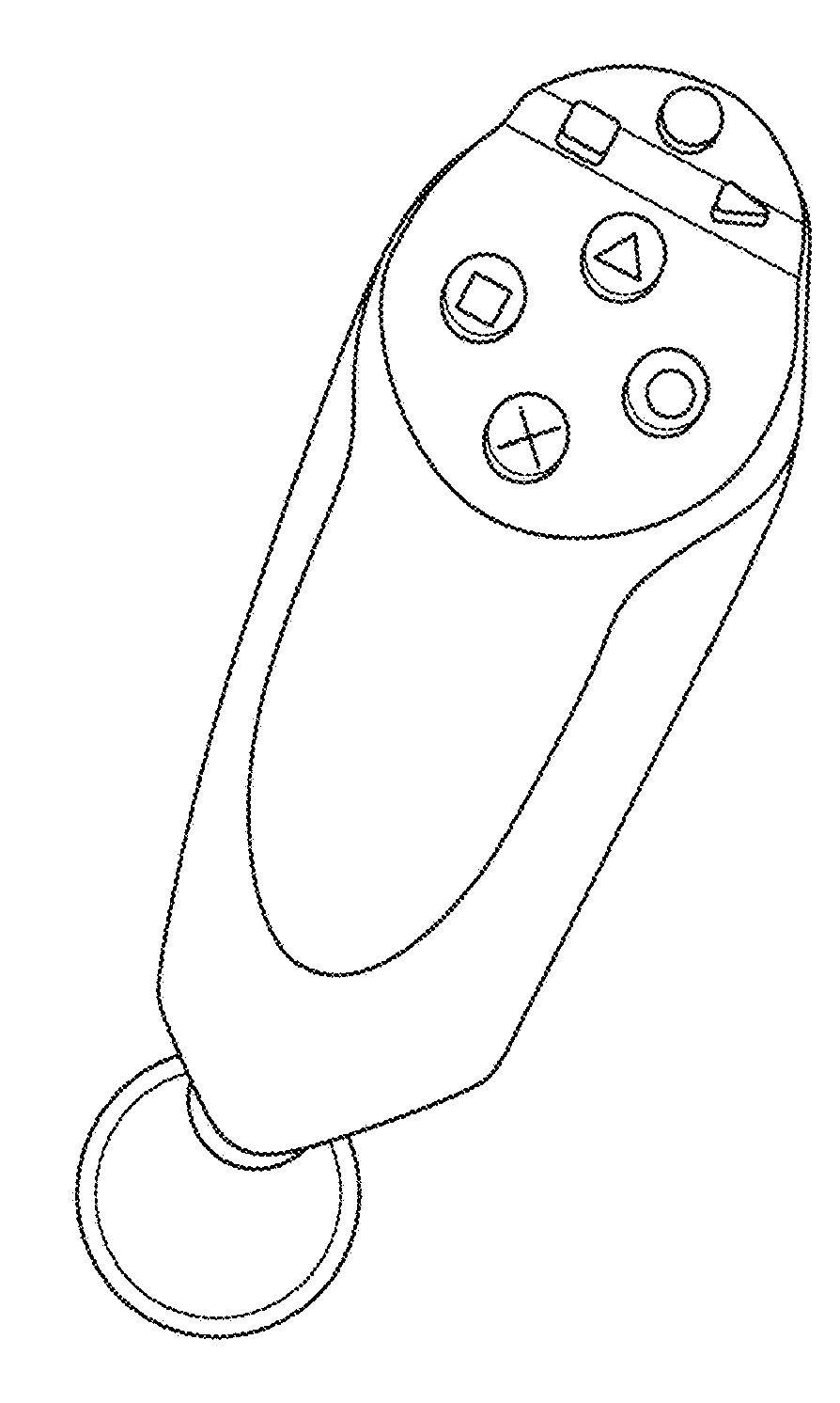
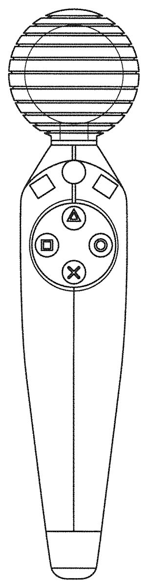
FIGS. 1A-Bshow embodiments of a game controller with a ball section attached. The ball attached to the controllers can be of different colors, and in one embodiment, the ball can light up. The color in the ball can be driven by RGB (Red Green Blue) Light-Emitting Diodes (LEDs) inside the ball. Additionally, the brightness of the illuminated ball can be controlled in order to track the ball under different camera exposure settings. In one embodiment, the color of the ball is used to differentiate controllers from different users and among controllers held by the same user on different hands.
Although a spherical ball is shown in the controllers ofFIGS. 1A and 1B, the ball can have other shapes for visual tracking purposes, such as a partial sphere, an imperfect sphere, an elongated ball (like one used in American football or in rugby), a cube-like shape, etc.
The controllers ofFIGS. 1A and 1Bare designed for one-hand use, but ball-attached two-hand controllers can also be tracked using embodiments described herein. In one embodiment, the two controllers held by the user on different hands are identical, and in another embodiment the controllers are different. Typically, the controllers will be very similar, being different just in the buttons at each controller. In one embodiment, the controller includes a Universal Serial Bus (USB) connection for charging the controller, Bluetooth for wireless communication with the console, and buttons such as start, select and PS.
In one embodiment, the ball or sphere is 4 cm. in diameter, but other sizes are also possible. Bigger sizes help with visual recognition. A ball with a 5 cm. diameter provides about 55 percent more pixels for image recognition than a 4 cm. ball.
FIGS. 1C-Edepict different operational modes for the game controller ofFIGS. 1A-B.FIG. 1Cshows a “reverse wand” operation, where the ball section is located at the bottom of the controller, and the top includes input buttons. In this configuration, the controller can be used as an arcade flight stick by pivoting on the sphere. In one embodiment, an inertial unit provides the angle of the “stick” (controller) and the twist, and the top surface includes a directional pad. In another embodiment, the top surface holds removable plates to change button configuration, as described below with respect toFIGS. 4A-4D. This mode of operation can be used in firing, driving, flying games, etc.
In one embodiment, the controller includes buttons for the index and middle finger in the reverse wand configuration. As a result, two reverse wand controllers provide the same functionality as a Sony DualShock®2 controller from Sony Computer Entertainment America Inc.
FIG. 1Dshows a controller behind held in a “pencil” configuration. The ball faces the camera for visual identification, and buttons in the body of the controller enable user input. This mode can be use in games where the controller is a paint brush, a flashlight, a pointer, a firing weapon, etc.FIG. 1Eillustrate the use of a controller in wand mode. In one embodiment, the wand includes two thumb buttons at the top of the handle and a trigger for the index finger, but other configurations are also possible. The wand mode can be used as a magic-wand, a music director's baton, a tennis racket, a hatchet or similar weapon, a tool such as a pick, an umbrella, a rope, etc.
FIGS. 2A-2Bshows other embodiments of a game controller with a ball attached. The body of controllers inFIGS. 2A and 2Bare spherical like the attached balls. The controllers have different button configurations and are intended for use in different hands. In one embodiment, the controllers are identical, and can be used either with the left or the right hand. The controllers ofFIGS. 2A and 2Bare held in a “baseball” configuration, that is, the controller is about the size of a baseball or a tennis ball and is held as a baseball in the palm of the hand. Similar to the configurations inFIGS. 1C to 1E, the controllers in2A and2B can be held with the ball attachment pointing in different directions, such as towards the camera, the floor, or the ceiling.
FIGS. 3A-3Bdepict different embodiments of a ball-attached game controller. The controllers are slimmer and designed for light weight applications.
FIGS. 4A-Dshow an embodiment of a ball-attached game controller with interchangeable face-plates.FIG. 4Ashows a controller, similar to the controllers inFIGS. 1A-B, but with interchangeable face-plates. The face-plates forFIGS. 4B-4Dcan be attached to the controller, either at the top or at the side. In another embodiment, the sizes of the face plates are different for the slots on the top and the side, and the face plates for the top are not exchangeable with the face plates for the side.FIGS. 4B-4Dshow a D-pad attachment, an action-buttons pad, and a touch pad, respectively. The attachments include electrical connections and a mechanical grip that snaps the attachments securely when placed on the controller.
FIG. 5shows a schematic diagram of a multiplayer environment and the use of visual information to determine the locations of the different controllers held by the players, according to one embodiment. Image capture device508obtains an image of playing field518and the image is analyzed to obtain the location of ball-attached controllers C1, C2, C4and C5. Distances dz1, dz2, dz4, and dz5are estimated by analyzing the shape of the respective balls in the captured image. Computing system502, uses the obtained coordinates and distances to produce representations of the players in screen504, avatars512aand512brespectively. A typical distance for good image recognition is about 10 ft (3 mtr). One advantage of using visual recognition is that improvements in image capture and image recognition can be included in the system without having to change the controller.
FIGS. 6A-6Dillustrate different embodiments for assigning a geometric shape to a perceived shape from a captured image.FIG. 4Ashows some of the problems with determining where the “true” geometric shape (i.e. the ball) given a captured image. Since the ball is a sphere, the goal is to determine the circle that corresponds to the ball in the image captured by the camera. There are different ways of assigning a circle to a perceived shape, such as the one inFIG. 6A, depending on the methodology. For example, a circle inside the received shape could be selected in order to assure that all pixels in the circle are pixels corresponding to the ball, or a circle could be selected that would contain all the shape pixels and the minimum amount of non-shape pixels. Alternatively, the algorithm may focus on detecting the outside curves delimiting the captured shape and then fit a circle that approximates those curves.
In many cases, the number of pixels captured associated with the ball is small. In one embodiment, a ball located at 10 ft. (3 mt.) generates an image where the radius of the circle is 4 pixels. In other words, each pixel corresponds to a depth of 2.5 ft. If a pixel is missed because of noise or because of an inaccurate algorithm, then the location of the player jumps 2.5 ft. As a result, pixel counting by itself does not provide an accurate measure of depth. Additionally, if the ball gets occluded due to the movement of the controller, only a partial image may be captured by the camera. Curve fitting becomes critical to analyze the perceived shape and determine the best location and shape of the ball.
FIG. 6Billustrates estimating the center and the radius r of the circle. The depth, also known herein as z, is related to the area of the ball, and is proportional to 1/r. In one embodiment, the method finds the pixels that correspond to the visual identification of the ball. The pixels associated with the ball are counted to determine the area, and then the center and the r are calculated based on the size.
In another embodiment, the periphery of the shape inFIG. 6Bis analyzed to determine the curve surrounding the shape. The curve is analyzed in order to determine the circle that best fits the curve. In one embodiment, the circle chosen is the circle that would have the smallest sum of the unique areas delimited by the circle and the curve surrounding the perceived shape.
FIG. 6Cillustrates the difficulty in finding an associated circle given an imperfect shape. Visually inspecting the shape, it can be inferred that only a partial section of the ball has been captured. Doing a straight pixel count to determine the area would not produce an accurate result. In one embodiment, the method checks for the “fuzzy” boundaries around the edges, which may be caused by shadows, light variations, etc., and determines the shape of the outside curve. The perimeter curve of the shape is analyzed to determine the center, also referred to herein as “centroid”, and to determine the radius that best fits the area and the outside curve.
FIG. 6Dillustrates the “fit the longest stick” method. As previously described, the image is analyzed and a shape of the captured ball is determined. The method determines the longest straight segment, or “stick,” that fits inside the shape. The longest segment is then considered the diameter of the circle associated with the ball.
FIG. 7illustrates how to use subpixel analysis to find pixels corresponding to the ball section in accordance with one embodiment. In many display and image-acquisition systems are, the pixel grid is divided into single-color regions that contribute to the displayed or sensed color when viewed at a distance. In some displays, such as LCD, LED, and plasma displays, these single-color regions are separately addressable elements, which have come to be known as subpixels. For example, LCDs typically divide each pixel702into three subpixels704,706, and708.
In one embodiment, the pixel analysis focuses on just one color, such as blue. In other embodiments, the analysis focuses on the combination of two subpixels, improving accuracy but requiring more computation. Additionally, the analysis of one pixel is not constrained to analyzing the pixel, or the subpixels in the pixel, and nearby pixels are analyzed to improve accuracy and reduce the effects of noise or other conditions such as inconsistent lighting.
FIG. 8shows the effects of blurring an image to improve shape detection according to one embodiment of the invention. The image is taking with the camera slightly out of focus causing a blurring effect on the ball, which causes the perceived area of the ball to be bigger than an image taken without blurring. A larger area means more pixels for analysis and improved accuracy.
FIG. 9depicts the use of several consecutive captured images to determine ball location according to one embodiment, referred to herein as smoothing. In one embodiment, the captured images are not analyzed in isolation. The information from one image is compared with previously taken images. If the image-taking frequency is high enough, consecutive images will be similar, even after factoring the movement of the controller. As a result, the information from previous images can be used to detect sudden anomalous pixel variations, which are likely caused by noise, bad lighting, ball occlusion, etc.
In one embodiment, the information from previous images is weighted in inverse proportion to their age, that is, older images are given smaller weights, as the information that they convey becomes less relevant.
FIG. 10illustrates one embodiment for taking an image from a reduced area156of the playing field152to increase accuracy. The computer system keeps track of the movement of the ball, together with the controller attached to the ball, and has the expectation that the ball will be in about the same place as the last time an image was taken, assuming the video taking frequency is adequate to allow for small movements of the controller between images. In one embodiment, the video taking camera as zoom capabilities and takes image154of reduced area156where the ball was in the last image and a buffer area around the ball to allow for movement of the controller. The image of the reduced area has higher resolution and provides more pixels associated with the ball for better location determination.
As a result, the field of play where the ball is present is reduced when taking the image of the reduced area, but this can be easily compensated by tracking the movement of the ball in order to capture zoomed-in images centered around the last known position of the ball.
In another embodiment, the camera is able to zoom-in only in the center of the field of play. In this case, the zoom-in function is only used when the ball is located towards the center of the field of play. This will cause the resolution to be better when the player is located around the center of the field of play and worse when the ball is located in the periphery of the field of play.
FIG. 11depicts image recognition of a ball with a small number of pixels, according to one embodiment. As previously described with respect toFIG. 6A, recognition of a ball when few pixels are available can cause big changes in the perceived shape when even one pixel is missed or miscalculated. The problem of few-pixel availability can be aggravated when the ball moves across pixel boundaries. In a first position160of the ball, the method perceives the ball as having four pixels. In one embodiment, the method determines that a pixel is associated with the color of the ball when at least fifty percent of the pixel corresponds to the ball, but other embodiments may use other percentages as the threshold. As the ball moves to second position162, the method perceives 7 pixels associated with the ball. Because the ball corresponds to a few pixels, the position of the ball in the pixel grid is a factor under the scenario inFIG. 11. In addition, the problem can be compounded with other factors such as noise and rasterization.
One embodiment solves the small number of pixels problem by using a higher resolution camera.FIG. 12depicts one embodiment for image recognition using a high resolution camera. Because the ball includes a larger number of pixels, small movements of the ball across the pixel grid will have a smaller impact on shape recognition than when using a lower resolution camera.
FIGS. 13A-Cillustrate ball detection using an illuminated ring movable to face the camera in accordance with one embodiment. Controller170has a ball section172attached for visual recognition based on images taken with image capture device180. Ball section172includes an inner sphere or ball174. Ball174has a plurality of light sources178a-nthat form a visual ring facing image capture device180. In one embodiment, the light sources correspond to the ends of optical wires that shine the light received from the corresponding optic wire. In another embodiment, the light sources correspond to LEDs.
Inside ball174is configured to move inside ball172in order to substantially face capture device180. In one embodiment, ball174is suspended in a liquid to facilitate the movement.FIG. 13Bshows the same controller170ofFIG. 13Aafter the controller has moved his orientation about 45 degrees. Although controller170has moved, inside ball174has rotated with respect to controller170so the illuminated ring still faces capture device180. As a result, the image captured will be a ring, which aids in determining the location of the ball, as described below with respect toFIGS. 15A-B.
In another embodiment, the ring can be illuminated with different color lights to enhance image recognition, or to differentiate different controllers in the field of play. In yet another embodiment, more than one ring are available for illumination, where only one ring is illuminated at one time, or where a plurality of rings are illuminated at the same time for image recognition.FIG. 13Cillustrates a frontal view of the ball section, as seen by image capture device180.
FIGS. 14A-Hillustrate detection of a distinguishable ring in the ball section, according to one embodiment.FIG. 14Aincludes controller190with ball192attached, which includes inside ball194with illuminated ring196. Unlike the controllers ofFIGS. 13A-C, the controllers inFIGS. 14A-Cdo not have a ball that moves with respect to the controller. Thus, as the controller moves from the substantially vertical position inFIG. 14Ato a different orientation, as inFIG. 14B, ring196goes from facing image capture device180straight, to facing the image capture device at an angle with respect to the line connecting the ball with capture device180. InFIG. 14A, the image captures an illuminated circle, and inFIG. 14B, the image captures an elliptical ring. In most controller positions where the ring is not facing the camera straight, the image will only capture about half of the ring because the other half section is hidden in the posterior non-visible side of the ball.
FIG. 14Cshows the image captured by the camera when the controller is in the position shown inFIG. 14B.FIG. 14Dillustrates the effects of changing the orientation of the controller with respect to the camera, according to different axis x, y, and z. The controller at position250is facing the camera, thus the camera only “sees” the ball. The rest of the positions correspond to changing the orientation of the controller within a different axis. This can be visualized by having a player holding the controller aiming directly at the camera in position250. Then the player changes the position of the controller, just by rotating the elbow in the x, y, or z direction.
As the controller turns in the x direction (horizontally), a bigger part of the controller will be visible (the actual hand of the player is ignored), and the ring will rotate until the controller is oriented horizontally256, and the ring will be perceived sideways as a line. The similar effect can be observed when the controller rotates in the y direction (vertically). Movement in the z (depth) direction will cause the perceived ring to change also. The effect of the size of the ball becoming smaller as the ball moves away from the camera is ignored inFIG. 14D.
FIG. 14Eshows the shape of the ring, as perceived by the camera, according to the movement of the controller as discussed inFIG. 14D. The perfect circle250shown when the ball faces the camera gets distorted as the ball moves and becomes an ellipse, where the small axis becomes smaller and smaller as the ring moves further away from the position facing the camera.
It should be noted that an ellipse is a collection of points in a plane such that the sum of the distances to two fixed points is a constant. The two fixed points are called foci. If the two foci coincide, then the ellipse is a circle. In other words, a circle is a special case of an ellipse. The embodiments described herein referring to an ellipse are designed to cover the case where the ellipse is a circle, because the circle is just one form of an ellipse, such as circle250ofFIG. 14E.
FIG. 14Fdepicts a controller facing the camera and moving away in the z direction. As expected, the ring becomes smaller as the ball gets further away from the camera.
In another embodiment, the ball includes different illuminated patterns, such as the three rings ofFIG. 14G.FIG. 14Hshows a ball with two rings perpendicular to each other. In yet another embodiment, the ball has an illuminated ring, such as the one inFIG. 14E, however the ring has a different orientation when the controller is aiming straight at the camera. The circle formed by the illuminated ring is perpendicular to the camera, where the camera would perceive a straight line when the controller is oriented straight towards the camera, such as any of the rings shown inFIG. 14H. In yet another embodiment, the ring is not completely illuminated because the part of the ring facing the controller would rarely be captured by the camera, resulting in savings in manufacturing of the ring, as well as in battery consumption. In one embodiment, the ring is only illuminated along a 270 degrees arc of the ring, but other values are also possible.
FIGS. 15A-Bdepicts a method to estimate a complete ring area from a partial arc section.FIG. 15Ashows a captured ring350, where only about half of ring352has been detected, such as when the ball is occluded. In general, it is easier to find the center of an arc with partial information, than finding the center of a circle with partial information. As described hereinabove with respects toFIGS. 6A-6D, determining the center of a circle is not a straightforward task with less than perfect information. On the other hand, it is relatively easy to find the center of an arc with information about half the arc, as inFIG. 15A.
By analyzing the curve corresponding to the ring, radius354can be estimated together with the center of the arc.FIG. 15Bshows a scenario where a small section356of the ring has been captured. However, the same method used inFIG. 15Acan be used to determine a circle with a high level of accuracy. Although less information is available, the analysis of the curve detected produces accurate results because only a small number of circles would fit this curve, and the variation between the circles is small, that is, the circles produce similar values of r and centers not far apart from each other.
In the case where the angle of the ring with respect to the camera can change, such as the ones corresponding toFIGS. 14A-D, the analysis is extended to cover ellipses. For example, given a perceived ring such as the half ellipse252ofFIG. 14E, the method analyses the ellipse to estimate the long and the short axis of the ellipse, as well as the center of the ellipse.
FIG. 16shows and embodiment where the ball vibrates to increase the perceived ball surface. As the ball vibrates, a longer perceived area is captured by the camera. This method can be combined with smoothing, such as the algorithm depicted inFIG. 9, to improve location determination. Because the ball vibrates from respect to each center, the comparison or averaging of consecutive images will help determine the true center with higher accuracy.
FIGS. 17A-Bdepict embodiments of a ball that can change size or appearance to improve detection.FIG. 17Adepicts a ball that can change size. When player450ais closer to camera456sitting atop display458, ball454aattached to controller452has a predetermined size. When the player is in location450b, controller452and attached ball are farther away from the screen. As the ball gets relatively smaller in the image captured by the camera, determining the ball's location becomes harder. In order to improve detection, ball454bis expanded to improve accuracy. The bigger ball translates into more pixels in the images captured, making determining the location of the controller more accurate. Several ways to inflate the ball are possible, such as inflation, a motor, etc.
In one embodiment, controller452is in communication with computing device460to convey the size of the ball. In another embodiment, computing device460sends commands to the controller to make the ball bigger as the number of pixels detected in the ball become lower than a predetermined threshold.
FIG. 17Bshows controller with ball460that can change, modify or improve its appearance to improve detection depending on the lighting conditions in the field of play. If the field of play is nearby a source of light (natural or artificial), such as a window that can receive light from sun462, then visual detection may be affected depending on the time of the day or night and the amount of light in the field of play. The appearance of the ball also is affected by the angle of impact from the sun rays. For example, the appearance of the ball will be different if the sunlight hits the ball at the front, back, or side. Similarly, lamp464(or the like) can affect visual detection depending on whether the lamp is on or off.
In one embodiment, ball460includes a light source inside that can be turned on or off to improve ball460visibility. The light source can be turned on by the player or by the computer system in communication with the controller including ball460. In another embodiment, ball460can include a clear shell. In another embodiment, the shell can be frosted. Still further, the shell (either clear or frosted), can take on any shade, color or texture. For example, if the shell is frosted or has a shade, then the ball460can be made to appear darker when not illuminated. An example shade can be a gray, black, silver, or combinations of colors, so long as the color or shade provides good differentiating contrast, when placed in a particular environment. The shell can be made from many materials, such as plastics, rubber, glass, foam, molded materials, etc. And, these materials can take on any color, whether applied, dyed or molded.
Still further, the light source inside ball460can make ball460illuminated in different colors, such as white or yellow, while other colors are also possible. The illuminated ball can improve detection in low ambient light conditions, while a darker color ball improves detection in situations with bright light.
FIG. 18shows an embodiment of game controller470with a ball section472enclosed in shell478. Shell478lets light go thorough so the ball can be detected visually. In one embodiment, shell478lets light474come out in the direction from the ball towards the camera, but shell478does not let light476coming from the outside to go through. This way, there is less interference with the illuminated ball inside.
In another embodiment, shell478can selectively filter the light passing thorough, such as for example letting blue light go through in order to identify a blue ball.
FIGS. 19A-Bdescribe a controller with sensors for improving movement tracking, according to one embodiment. Different embodiments include different combinations of sensors, such as magnetometers, accelerometers, gyroscopes, etc.
An accelerometer is a device for measuring acceleration and gravity induced reaction forces. Single and multiple axis models are available to detect magnitude and direction of the acceleration in different directions. The accelerometer is used to sense inclination, vibration, and shock. In one embodiment, three accelerometers are used to provide the direction of gravity, which gives an absolute reference for 2 angles (world-space pitch and world-space roll). Controllers can suffer accelerations exceeding 5 g, therefore accelerometers able to operate with forces exceeding 5 g are used inside controller550.
A magnetometer measures the strength and direction of the magnetic field in the vicinity of the controller. In one embodiment, three magnetometers552are used within the controller, ensuring an absolute reference for the world-space yaw angle. The magnetometer is designed to span the earth magnetic field, which is ±80 microtesla. Magnetometers are affected by metal, and provide a yaw measurement that is monotonic with actual yaw. The magnetic field may be warped due to metal in the environment, which causes a warp in the yaw measurement. If necessary, this warp can be calibrated using information from the gyros (see below) or the camera. In one embodiment, accelerometer554is used together with magnetometer552to obtain the inclination and azimuth of the controller.
A gyroscope is a device for measuring or maintaining orientation, based on the principles of angular momentum. In one embodiment, three gyroscopes provide information about movement across the respective axis (x, y and z) based on inertial sensing. The gyroscopes help in detecting fast rotations. However, the gyroscopes can drift overtime without the existence of an absolute reference. This requires, resetting the gyroscopes periodically, which can be done using other available information, such as visual tracking of ball558, accelerometer, magnetometer, etc. A hand-held device can rotate faster than 500 degrees/sec, so a gyroscopes with an spec of more than 1000 degrees/sec is recommended, but smaller values are also possible.
The information from the different sources can be combined for improved location and orientation detection. For example, if the ball disappears from view, the accelerometer's orientation sensing is used to detect that the controller is facing away from the camera. In one embodiment, controller550includes a speaker to provide audio feedback to the player. For example, the controller can produce a beep when the ball is not visible by the camera, prompting the player to orientate the controller in the right direction, or to come back into the field of play.
In the embodiment shown inFIG. 19B, the visual and sensor-originated information from several frames is analyzed to determine the location of the controller as well as the controller's orientation. By analyzing the information from several frames, the sensor information related to movement and orientation of the controller is “smoothed” over several frames. Once the trajectory of the ball is determined over several frames, the sensor information is analyzed to find the corresponding orientation of the controller that produces the given trajectory given the corresponding sensor information for those frames.
FIG. 20depicts using different sources of information to assess controller position in accordance with one embodiment. Controller570includes a ball section attached, as well as accelerometers, as previously described with respect toFIG. 19. The computing system uses visual tracking of the ball in controller570. When the ball gets occluded, such as when the controller follows trajectory582that causes occlusion when the ball is behind the player's head, the system uses dead reckoning. Dead reckoning (DR) is the process of estimating a current position based upon a previously determined position, or fix, and advancing that position based upon known speed, elapsed time, and course.
As the controller's ball follows path582, the computing system tracks the controller under curve580. Once the ball gets occluded, the accelerometers are reset and the system begins using dead reckoning. It should be noted, that dead reckoning loses accuracy over time, thus complementing dead reckoning with other location information is desirable for accurate tracking. Data from the accelerometers is always being captured, but may not be always used by the system.
Dead reckoning is used while the ball is occluded (region574). Once the ball is back on sight, visual tracking takes over in region578. In one embodiment, dead reckoning can be combined at times with visual tracking, such as the region when the ball is coming out of invisibility and visual information is still not very accurate because of partial occlusion, or because of the lack of visual history to track the ball's movement.
FIGS. 21A-Cdescribe the use of an input wheel in the controller to initiate computer actions, according to one embodiment. Controller orientation is combined with wheel movement to generate actions in the computing system. For example, a player may place the controller in the x, y, or z direction and then rotate the wheel, causing an icon in the screen to move in that direction. In fact, the controller does not have to be orientated along an axis, and any orientation can cause a corresponding movement on the screen. For example, a controller placed at 45 degrees between the x and y axis, will cause an icon on display654to move in that direction. Additionally, the wheel can be used to navigate menus. For example, to move vertically or horizontally across menus, according to the orientation of the controller.FIG. 21Ashows controller650including wheel658A in a vertical or longitudinal orientation.FIG. 21Bshows controller670including wheel672in a horizontal or latitudinal orientation. The top part of wheel672is used by the player to input commands.FIG. 21Cshows controller674that also includes wheel676in a horizontal or latitudinal orientation. Wheel676wraps around the controller and moves perpendicularly680relative to the holding portion678of the body of the controller. The complete circumference of wheel676is available to the user which can operate the wheel from the top, the sides, the bottom, or any other angle, and with the possibility of operating the wheel using different fingers.
FIG. 22illustrates hardware and user interfaces that may be used to determine controller location, in accordance with one embodiment of the present invention.FIG. 22schematically illustrates the overall system architecture of the Sony® Playstation 3® entertainment device, a console that may be compatible for implementing a three-dimensional controller locating system in accordance with one embodiment of the present invention. A system unit1400is provided, with various peripheral devices connectable to the system unit1400. The system unit1400comprises: a Cell processor1428; a Rambus® dynamic random access memory (XDRAM) unit1426; a Reality Synthesizer graphics unit1430with a dedicated video random access memory (VRAM) unit1432; and an I/O bridge1434. The system unit1400also comprises a Blu Ray® Disk BD-ROM® optical disk reader1440for reading from a disk1440aand a removable slot-in hard disk drive (HDD)1436, accessible through the I/O bridge1434. Optionally the system unit1400also comprises a memory card reader1438for reading compact flash memory cards, Memory Stick® memory cards and the like, which is similarly accessible through the I/O bridge1434.
The I/O bridge1434also connects to six Universal Serial Bus (USB) 2.0 ports1424; a gigabit Ethernet port1422; an IEEE 802.11b/g wireless network (Wi-Fi) port1420; and a Bluetooth® wireless link port1418capable of supporting of up to seven Bluetooth connections.
In operation, the I/O bridge1434handles all wireless, USB and Ethernet data, including data from one or more game controllers1402-1403. For example when a user is playing a game, the I/O bridge1434receives data from the game controller1402-1403via a Bluetooth link and directs it to the Cell processor1428, which updates the current state of the game accordingly.
The wireless, USB and Ethernet ports also provide connectivity for other peripheral devices in addition to game controllers1402-1403, such as: a remote control1404; a keyboard1406; a mouse1408; a portable entertainment device1410such as a Sony Playstation Portable® entertainment device; a video camera such as an EyeToy® video camera1412; a microphone headset1414; and a microphone1415. Such peripheral devices may therefore in principle be connected to the system unit1400wirelessly; for example the portable entertainment device1410may communicate via a Wi-Fi ad-hoc connection, whilst the microphone headset1414may communicate via a Bluetooth link.
The provision of these interfaces means that the Playstation 3 device is also potentially compatible with other peripheral devices such as digital video recorders (DVRs), set-top boxes, digital cameras, portable media players, Voice over IP telephones, mobile telephones, printers and scanners.
In addition, a legacy memory card reader1416may be connected to the system unit via a USB port1424, enabling the reading of memory cards1448of the kind used by the Playstation® or Playstation 2® devices.
The game controllers1402-1403are operable to communicate wirelessly with the system unit1400via the Bluetooth link, or to be connected to a USB port, thereby also providing power by which to charge the battery of the game controllers1402-1403. Game controllers1402-1403can also include memory, a processor, a memory card reader, permanent memory such as flash memory, light emitters such as LEDs or infrared lights, microphone and speaker for ultrasound communications, an acoustic chamber, a digital camera, an internal clock, a recognizable shape such as a spherical section facing the game console, and wireless communications using protocols such as Bluetooth®, WiFi™, etc.
Game controller1402is a controller designed to be used with two hands, and game controller1403is a single-hand controller with a ball attachment, as previously described inFIGS. 1A-4A. In addition to one or more analog joysticks and conventional control buttons, the game controller is susceptible to three-dimensional location determination. Consequently gestures and movements by the user of the game controller may be translated as inputs to a game in addition to or instead of conventional button or joystick commands. Optionally, other wirelessly enabled peripheral devices such as the Playstation™ Portable device may be used as a controller. In the case of the Playstation™ Portable device, additional game or control information (for example, control instructions or number of lives) may be provided on the screen of the device. Other alternative or supplementary control devices may also be used, such as a dance mat (not shown), a light gun (not shown), a steering wheel and pedals (not shown) or bespoke controllers, such as a single or several large buttons for a rapid-response quiz game (also not shown).
The remote control1404is also operable to communicate wirelessly with the system unit1400via a Bluetooth link. The remote control1404comprises controls suitable for the operation of the Blu Ray™ Disk BD-ROM reader1440and for the navigation of disk content.
The Blu Ray™ Disk BD-ROM reader1440is operable to read CD-ROMs compatible with the Playstation and PlayStation 2 devices, in addition to conventional pre-recorded and recordable CDs, and so-called Super Audio CDs. The reader1440is also operable to read DVD-ROMs compatible with the Playstation 2 and PlayStation 3 devices, in addition to conventional pre-recorded and recordable DVDs. The reader1440is further operable to read BD-ROMs compatible with the Playstation 3 device, as well as conventional pre-recorded and recordable Blu-Ray Disks.
The system unit1400is operable to supply audio and video, either generated or decoded by the Playstation 3 device via the Reality Synthesizer graphics unit1430, through audio and video connectors to a display and sound output device1442such as a monitor or television set having a display1444and one or more loudspeakers1446. The audio connectors1450may include conventional analogue and digital outputs whilst the video connectors1452may variously include component video, S-video, composite video and one or more High Definition Multimedia Interface (HDMI) outputs. Consequently, video output may be in formats such as PAL or NTSC, or in 720p, 1080i or 1080p high definition.
Audio processing (generation, decoding and so on) is performed by the Cell processor1428. The Playstation 3 device's operating system supports Dolby® 5.1 surround sound, Dolby® Theatre Surround (DTS), and the decoding of 7.1 surround sound from Blu-Ray® disks.
In the present embodiment, the video camera1412comprises a single charge coupled device (CCD), an LED indicator, and hardware-based real-time data compression and encoding apparatus so that compressed video data may be transmitted in an appropriate format such as an intra-image based MPEG (motion picture expert group) standard for decoding by the system unit1400. The camera LED indicator is arranged to illuminate in response to appropriate control data from the system unit1400, for example to signify adverse lighting conditions. Embodiments of the video camera1412may variously connect to the system unit1400via a USB, Bluetooth or Wi-Fi communication port. Embodiments of the video camera may include one or more associated microphones and also be capable of transmitting audio data. In embodiments of the video camera, the CCD may have a resolution suitable for high-definition video capture. In use, images captured by the video camera may for example be incorporated within a game or interpreted as game control inputs. In another embodiment the camera is an infrared camera suitable for detecting infrared light.
In general, in order for successful data communication to occur with a peripheral device such as a video camera or remote control via one of the communication ports of the system unit1400, an appropriate piece of software such as a device driver should be provided. Device driver technology is well-known and will not be described in detail here, except to say that the skilled man will be aware that a device driver or similar software interface may be required in the present embodiment described.
FIG. 23illustrates additional hardware that may be used to process instructions, in accordance with one embodiment of the present invention. Cell processor1428has an architecture comprising four basic components: external input and output structures comprising a memory controller1560and a dual bus interface controller1570A, B; a main processor referred to as the Power Processing Element1550; eight co-processors referred to as Synergistic Processing Elements (SPEs)1510A-H; and a circular data bus connecting the above components referred to as the Element Interconnect Bus1580. The total floating point performance of the Cell processor is 218 GFLOPS, compared with the 6.2 GFLOPs of the Playstation 2 device's Emotion Engine.
The Power Processing Element (PPE)1550is based upon a two-way simultaneous multithreading Power1470compliant PowerPC core (PPU)1555running with an internal clock of 3.2 GHz. It comprises a 512 kB level 2 (L2) cache and a 32 kB level 1 (L1) cache. The PPE1550is capable of eight single position operations per clock cycle, translating to 25.6 GFLOPs at 3.2 GHz. The primary role of the PPE1550is to act as a controller for the Synergistic Processing Elements1510A-H, which handle most of the computational workload. In operation the PPE1550maintains a job queue, scheduling jobs for the Synergistic Processing Elements1510A-H and monitoring their progress. Consequently each Synergistic Processing Element1510A-H runs a kernel whose role is to fetch a job, execute it and synchronized with the PPE1550.
Each Synergistic Processing Element (SPE)1510A-H comprises a respective Synergistic Processing Unit (SPU)1520A-H, and a respective Memory Flow Controller (MFC)1540A-H comprising in turn a respective Dynamic Memory Access Controller (DMAC)1542A-H, a respective Memory Management Unit (MMU)1544A-H and a bus interface (not shown). Each SPU1520A-H is a RISC processor clocked at 3.2 GHz and comprising 256 kB local RAM1530A-H, expandable in principle to 4 GB. Each SPE gives a theoretical 25.6 GFLOPS of single precision performance. An SPU can operate on 4 single precision floating point members, 4 32-bit numbers, 8 16-bit integers, or 16 8-bit integers in a single clock cycle. In the same clock cycle it can also perform a memory operation. The SPU1520A-H does not directly access the system memory XDRAM1426; the 64-bit addresses formed by the SPU1520A-H are passed to the MFC1540A-H which instructs its DMA controller1542A-H to access memory via the Element Interconnect Bus1580and the memory controller1560.
The Element Interconnect Bus (EIB)1580is a logically circular communication bus internal to the Cell processor1428which connects the above processor elements, namely the PPE1550, the memory controller1560, the dual bus interface1570A,B and the 8 SPEs1510A-H, totaling 12 participants. Participants can simultaneously read and write to the bus at a rate of 8 bytes per clock cycle. As noted previously, each SPE1510A-H comprises a DMAC1542A-H for scheduling longer read or write sequences. The EIB comprises four channels, two each in clockwise and anti-clockwise directions. Consequently for twelve participants, the longest step-wise data-flow between any two participants is six steps in the appropriate direction. The theoretical peak instantaneous EIB bandwidth for 12 slots is therefore 96B per clock, in the event of full utilization through arbitration between participants. This equates to a theoretical peak bandwidth of 307.2 GB/s (gigabytes per second) at a clock rate of 3.2 GHz.
The memory controller1560comprises an XDRAM interface1562, developed by Rambus Incorporated. The memory controller interfaces with the Rambus XDRAM1426with a theoretical peak bandwidth of 25.6 GB/s.
The dual bus interface1570A,B comprises a Rambus FlexIO® system interface1572A,B. The interface is organized into 12 channels each being 8 bits wide, with five paths being inbound and seven outbound. This provides a theoretical peak bandwidth of 62.4 GB/s (36.4 GB/s outbound, 26 GB/s inbound) between the Cell processor and the I/O Bridge700via controller170A and the Reality Simulator graphics unit200via controller170B.
Data sent by the Cell processor1428to the Reality Simulator graphics unit1430will typically comprise display lists, being a sequence of commands to draw vertices, apply textures to polygons, specify lighting conditions, and so on.
FIG. 24shows flow chart2400describing an embodiment for a method to determine a location in a field of play of a ball-attached game controller. In operation2402, the method obtains an image of the field of play where the game controller is present, and then finds pixels in the image associated with the ball connected to the game controller. In one embodiment, the image is scanned to find pixels that correspond to the color of the ball, and in another embodiment, subpixels analysis is used to find pixels associated with the ball, as previously described with respect toFIG. 7.
In operation2406, the method establishes an area encompassing the pixels that were found. A geometric shape is determined in operation2408based on the area associated with the ball. SeeFIGS. 6A-6D, 9, and 12for different embodiments of methods to perform area recognition. Once the geometric shape is determined, the method, in operation2410, calculates the location of the controller based on the geometric shape, where the center of the geometric shape indicates the horizontal and vertical location of the controller, and the size of the geometric shape determines the depth of the controller within the field of play. The calculated location is stored in a memory associated with the computer in operation2412, and the computer drives an action based on the stored location in operation2414.
FIG. 25includes a flow chart for a method to determine a location in a field of play of a ball with a distinguishable ring, according to one embodiment. This method is similar to the method previously described with respect toFIG. 24, but the method ofFIG. 25adds new considerations regarding the changes in shape of the ring as the controller moves within the three-dimensional space.
In operation2502, the method obtains an image of the field of play where the game controller is present, as seen inFIG. 5. The image is scanned in operation2504to find pixels associated with a ring in the ball section connected to the game controller. SeeFIGS. 13A-15Bfor different embodiments related to location determination based on the ring in the ball attached to the controller.
In operation2506, the method establishes an area encompassing the pixels found in operation2504, and, in operation2508, the method determines an ellipse based on the area associated with the ring. The location of the controller is calculated, in operation2510, based on the ellipse. The center of the ellipse indicates the horizontal and vertical location of the controller, and the size of the ellipse determines the depth of the controller within the field of play. The location is stored, during operation2212, in a memory associated with the computer. The computer drives an action in response to the location stored in operation2514.
Embodiments of the present invention may be practiced with various computer system configurations including hand-held devices, microprocessor systems, microprocessor-based or programmable consumer electronics, minicomputers, mainframe computers and the like. The invention can also be practiced in distributed computing environments where tasks are performed by remote processing devices that are linked through a wire-based or wireless network.
With the above embodiments in mind, it should be understood that the invention can employ various computer-implemented operations involving data stored in computer systems. These operations are those requiring physical manipulation of physical quantities. Any of the operations described herein that form part of the invention are useful machine operations. The invention also relates to a device or an apparatus for performing these operations. The apparatus can be specially constructed for the required purpose, or the apparatus can be a general-purpose computer selectively activated or configured by a computer program stored in the computer. In particular, various general-purpose machines can be used with computer programs written in accordance with the teachings herein, or it may be more convenient to construct a more specialized apparatus to perform the required operations.
The invention can also be embodied as computer readable code on a computer readable medium. The computer readable medium is any data storage device that can store data, which can be thereafter be read by a computer system. Examples of the computer readable medium include hard drives, network attached storage (NAS), read-only memory, random-access memory, CD-ROMs, CD-Rs, CD-RWs, magnetic tapes and other optical and non-optical data storage devices. The computer readable medium can include computer readable tangible medium distributed over a network-coupled computer system so that the computer readable code is stored and executed in a distributed fashion.
Although the method operations were described in a specific order, it should be understood that other housekeeping operations may be performed in between operations, or operations may be adjusted so that they occur at slightly different times, or may be distributed in a system which allows the occurrence of the processing operations at various intervals associated with the processing, as long as the processing of the overlay operations are performed in the desired way.
Although the foregoing invention has been described in some detail for purposes of clarity of understanding, it will be apparent that certain changes and modifications can be practiced within the scope of the appended claims. Accordingly, the present embodiments are to be considered as illustrative and not restrictive, and the invention is not to be limited to the details given herein, but may be modified within the scope and equivalents of the appended claims.
Claims
- A video game controller for wireless interfacing with a computing system, the video game controller comprising: an elongated body in a form of a handle, the elongated body having a first end and a second end;an object disposed at the second end of the elongated body, the second end being opposite to the first end along a longest dimension of the elongated body, the object having a shape for visual recognition;a light source exposed in the object, wherein the object is defined to be illuminated when the light source is active;buttons disposed between the first end and the second end of the elongated body;an inertial sensor disposed within the elongated body;and one or more circuits disposed in the elongated body, the one or more circuits defined to be in communication with the light source, the buttons, the inertial sensor, and an antenna, the antenna provided for wireless communication to and from the computing system.
- The video game controller as recited in claim 1 , wherein the shape of the object is selected from a group consisting of a spherical section, a partial sphere, an imperfect sphere, an elongated ball, or a cube.
- The video game controller as recited in claim 1 , wherein the object is translucent.
- The video game controller as recited in claim 1 , wherein the object is plastic.
- The video game controller as recited in claim 1 , wherein the light source is a light-emitting diode (LED).
- The video game controller as recited in claim 1 , wherein the light source provides one or more of a plurality of colors or a white light.
- The video game controller as recited in claim 1 , wherein the one or more circuits are operable to set the light source as active or as inactive.
- The video game controller as recited in claim 1 , wherein one of the buttons is a trigger button defined to be operable by an index finger of a hand holding the controller by the handle.
- The video game controller as recited in claim 1 , wherein the handle further includes a universal serial bus (USB) port in communication with the one or more circuits.
- The video game controller as recited in claim 1 , wherein the wireless communication includes at least one or more of Bluetooth, wireless network (WiFi), or ultrasound.
- The video game controller as recited in claim 1 , wherein the one or more circuits include a processor.
- The video game controller as recited in claim 1 , wherein the one or more circuits include a memory.
- The video game controller as recited in claim 1 , wherein the inertial sensor is defined by one or more of an accelerometer, a magnetometer, or a gyroscope in communication with the one or more circuits.
- A video game controller for wireless interfacing with a computing system, the video game controller comprising: an elongated body in a form of a handle, the elongated body having a first end and a second end;an object disposed at the second end of the elongated body, the second end being opposite to the first end along a longest dimension of the elongated body, the object being defined from a translucent material;a light source exposed in the object;buttons disposed between the first end and the second end of the elongated body;an inertial sensor disposed within the elongated body;and one or more circuits disposed in the elongated body, the one or more circuits defined to be in communication with the light source, the inertial sensor, the buttons, and an antenna, the antenna provided for wireless communication.
- The video game controller as recited in claim 14 , wherein a shape of the object is defined for visual recognition and is selected from a group consisting of a spherical section, a partial sphere, an imperfect sphere, an elongated ball, or a cube.
- The video game controller as recited in claim 14 , wherein the object is defined to be illuminated when the light source is active.
- The video game controller as recited in claim 14 , wherein the light source is a light-emitting diode (LED).
- The video game controller as recited in claim 14 , wherein the light source provides one or more of a plurality of colors or a white light.
- The video game controller as recited in claim 14 , wherein the one or more circuits are operable to set the light source as active or inactive.
- The video game controller as recited in claim 14 , wherein one of the buttons is a trigger button defined to be operable by an index finger.
- The video game controller as recited in claim 14 , wherein the handle further includes a universal serial bus (USB) port in communication with the one or more circuits.
- The video game controller as recited in claim 14 , wherein the one or more circuits include a processor.
- The video game controller as recited in claim 14 , wherein the one or more circuits include a memory.
- A video game controller for wireless interfacing with a computing system, the video game controller comprising: an elongated body in a form of a handle, the elongated body having a first end and a second end;an object disposed at the second end of the elongated body, the second end being opposite to the first end along a longest dimension of the elongated body, the object having a shape;a light source exposed in the object, wherein the object is defined to be illuminated when the light source is active;buttons disposed between the first end and the second end of the elongated body, wherein one of the buttons is a trigger button defined to be operable by an index finger;a universal serial bus (USB) port on the second end;a battery disposed within the elongated body;and one or more circuits disposed in the elongated body, the one or more circuits defined to be in communication with the light source, the buttons, the USB port, the battery, and an antenna, the antenna provided for wireless communication.
- The video game controller as recited in claim 24 , wherein the shape of the object is selected from a group consisting of a spherical section, a partial sphere, an imperfect sphere, an elongated ball, or a cube.
- The video game controller as recited in claim 25 , wherein the wireless communication includes at least one or more of Bluetooth, wireless network (WiFi), or ultrasound.
- The video game controller as recited in claim 24 , wherein the object is defined from translucent plastic.
- The video game controller as recited in claim 24 , wherein the light source is a light-emitting diode (LED).
- The video game controller as recited in claim 24 , wherein the light source provides one or more of a plurality of colors or a white light.
- The video game controller as recited in claim 24 , wherein the one or more circuits are operable to set the light source as active or as inactive.
- The video game controller as recited in claim 24 , wherein the one or more circuits include a processor.
- The video game controller as recited in claim 24 , wherein the one or more circuits include a memory.
- The video game controller as recited in claim 24 , wherein the video game controller further includes an inertial sensor inside the handle.
- A video game controller for wireless interfacing with a computing system, the video game controller comprising: an elongated body in a form of a handle, the elongated body having a first end and a second end;an object disposed at the second end of the elongated body, the second end being opposite to the first end along a longest dimension of the elongated body, the object having a shape of an imperfect sphere;a light source exposed in the object, wherein the object is defined to be illuminated when the light source is active;buttons disposed between the first end and the second end of the elongated body, wherein one of the buttons is a trigger button defined to be operable by an index finger of a hand holding the controller by the handle;an inertial sensor disposed within the elongated body;a battery disposed within the elongated body;and one or more circuits disposed in the elongated body, the one or more circuits defined to be in communication with the light source, the buttons, the inertial sensor, the battery, and an antenna, the antenna provided for wireless communication to and from the computing system.
- The video game controller as recited in claim 34 , wherein the light source is a light-emitting diode (LED).
- The video game controller as recited in claim 34 , wherein the light source provides one or more of a plurality of colors or a white light.
- The video game controller as recited in claim 34 , wherein the handle further includes a universal serial bus (USB) port in communication with the one or more circuits.
- A video game controller for wireless interfacing with a computing system, the video game controller comprising: an elongated body in a form of a handle, the elongated body having a first end and a second end;an object disposed at the second end of the elongated body, the second end being opposite to the first end along a longest dimension of the elongated body, the object being translucent, plastic, and having a shape for visual recognition;a light source exposed in the object, wherein the object is defined to be illuminated when the light source is active, wherein the light source is a light-emitting diode (LED), wherein the light source provides one or more of a plurality of colors or a white light;buttons disposed between the first end and the second end of the elongated body;an inertial sensor disposed within the elongated body;and one or more circuits disposed in the elongated body, the one or more circuits defined to be in communication with the light source, the buttons, the inertial sensor, and an antenna, the antenna provided for wireless communication to and from the computing system.
Disclaimer: Data collected from the USPTO and may be malformed, incomplete, and/or otherwise inaccurate.