U.S. Pat. No. 10,252,156
CONTROL CIRCUIT OF MASTER-SIDE GAME CONSOLE FOR ENABLING MULTIPLE VIDEO GAME CONSOLES TO TOGETHER EMULATE SAME STANDALONE MULTIPLAYER VIDEO GAME THROUGH NETWORKING CONNECTION
AssigneeREALTEK SEMICONDUCTOR CORP.
Issue DateDecember 7, 2017
Illustrative Figure
Abstract
A control circuit of a master-side game console includes: a processor and a storage circuit for storing a computer program product. The processor is arranged to operably execute the computer program product to perform following operations: establishing networking connection between the master-side game console and a client-side game console; receiving master-side input values generated by an user control device of the master-side game console; receiving client-side input values transmitted from the client-side game console; generating a target instruction based on the master-side input values and the client-side input values; transmitting the target instruction and a pseudo clock indicator value to the client-side game console; executing the target instruction in a master-side emulating environment based on the pseudo clock indicator value; and rendering an updated master-side game screen according to execution results of the target instruction and displaying the updated master-side game screen on a display device.
Description
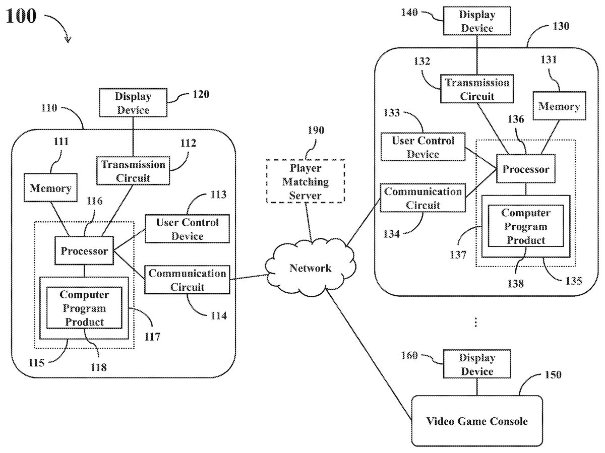
DETAILED DESCRIPTION Reference is made in detail to embodiments of the invention, which are illustrated in the accompanying drawings. The same reference numbers may be used throughout the drawings to refer to the same or like parts, components, or operations. FIG. 1shows a simplified functional block diagram of a video game emulating system100according to one embodiment of the present disclosure. The video game emulating system100comprises multiple video game consoles (e.g., the exemplary video game consoles110,130, and150shown inFIG. 1) capable of communicating with each other through a network, and multiple display devices (e.g., the exemplary display devices120,140, and160shown inFIG. 1) respectively coupled with the multiple video game consoles. The aforementioned network may be realized with Internet or Intranet and may adopt various communication protocols. Two or more video game consoles in the video game emulating system100may cooperate together through networking connections to conduct emulation operations of the same old fashion standalone multiplayer video game, so as to synchronously display the emulated results of the video game on different display devices in different geographical locations. This realizes a multiplayer gaming function that allows users in different geographical locations (e.g., different rooms, different buildings, different cities, or different countries) to play the same old fashion standalone multiplayer video game together, which is impossible for the traditional video game emulators. The term “old fashion standalone multiplayer video game” used throughout the description and the claims refers to various old multiplayer arcade games, TV games, or PC games, which were originally designed to be executed on a standalone game console, able to allow multiple users to play the same video game together by manipulating the same video game console at the same location, but incapable of supporting multiple users in different geographical locations to together play the same video game through networking connections. In the ...
DETAILED DESCRIPTION
Reference is made in detail to embodiments of the invention, which are illustrated in the accompanying drawings. The same reference numbers may be used throughout the drawings to refer to the same or like parts, components, or operations.
FIG. 1shows a simplified functional block diagram of a video game emulating system100according to one embodiment of the present disclosure. The video game emulating system100comprises multiple video game consoles (e.g., the exemplary video game consoles110,130, and150shown inFIG. 1) capable of communicating with each other through a network, and multiple display devices (e.g., the exemplary display devices120,140, and160shown inFIG. 1) respectively coupled with the multiple video game consoles. The aforementioned network may be realized with Internet or Intranet and may adopt various communication protocols.
Two or more video game consoles in the video game emulating system100may cooperate together through networking connections to conduct emulation operations of the same old fashion standalone multiplayer video game, so as to synchronously display the emulated results of the video game on different display devices in different geographical locations. This realizes a multiplayer gaming function that allows users in different geographical locations (e.g., different rooms, different buildings, different cities, or different countries) to play the same old fashion standalone multiplayer video game together, which is impossible for the traditional video game emulators.
The term “old fashion standalone multiplayer video game” used throughout the description and the claims refers to various old multiplayer arcade games, TV games, or PC games, which were originally designed to be executed on a standalone game console, able to allow multiple users to play the same video game together by manipulating the same video game console at the same location, but incapable of supporting multiple users in different geographical locations to together play the same video game through networking connections.
In the video game emulating system100, the video game consoles have similar main architecture with each other. As shown inFIG. 1, for example, the video game console110comprises a memory111, a transmission circuit112, an user control device113, a communication circuit114, and a control circuit115. The control circuit115comprises a processor116and a storage circuit117, while the storage circuit117is stored with a computer program product118. The video game console130comprises a memory131, a transmission circuit132, an user control device133, a communication circuit134, and a control circuit135. The control circuit135comprises a processor136and a storage circuit137, while the storage circuit137is stored with a computer program product138.
In the video game console110, the memory111is configured to operably store data required for the operations of the control circuit115or other circuits. The transmission circuit112is configured to operably transmit audio and video data to the corresponding display device120for displaying. The user control device113is configured to operably allow an user to input game control commands therefrom. The communication circuit114is configured to operably communicate data with other remote devices through the network. The control circuit115is coupled with the memory111, the transmission circuit112, the user control device113, and the communication circuit114. The processor116of the control circuit115is configured to operably execute the computer program product118stored in the storage circuit117so as to control the operations of the above components of the video game console110.
In the video game console130, the memory131is configured to operably store data required for the operations of the control circuit135or other circuits. The transmission circuit132is configured to operably transmit audio and video data to the display device140for displaying. The user control device133is configured to operably allow an user to input game control commands therefrom. The communication circuit134is configured to operably communicate data with other remote devices through the network. The control circuit135is coupled with the memory131, the transmission circuit132, the user control device133, and the communication circuit134. The processor136of the control circuit135is configured to operably execute the computer program product138stored in the storage circuit137so as to control the operations of the above components of the video game console130.
The computer program product118stored in the storage circuit117may be realized with one or more application program modules. For example,FIG. 2shows a simplified functional module diagram of the computer program product118inFIG. 1according to one embodiment of the present disclosure. In this embodiment, the computer program product118comprises a video and audio processing module210, a pseudo clock control module220, a networking module230, an user command receiving module240, and an emulator module250.
The computer program product138stored in the storage circuit137may be realized with one or more application program modules. For example,FIG. 3shows a simplified functional module diagram of the computer program product138inFIG. 1according to one embodiment of the present disclosure. In this embodiment, the computer program product138comprises a video and audio processing module310, a pseudo clock control module320, a networking module330, an user command receiving module340, and an emulator module350.
In practice, each of the memories111and131may be realized with an appropriate volatile memory circuit or non-volatile memory circuit. Each of the transmission circuits112and132may be realized with an appropriate audio and video transmission circuit complying with appropriate standard specifications. Each of the user control devices113and133may be realized with one or more appropriate joysticks, keyboards, touch panels, computer mice, tracking balls, mind control devices, a combination of the above devices, or any device that can convert user's intend to control signals/keycodes to user control circuit. Each of the communication circuits114and134may be realized with a wired networking interface, a wireless networking interface, or a hybrid circuit integrated with the functionalities of the above two interfaces. Each of the processors116and136may be realized with one or more appropriate computing circuits. Each of the storage circuits117and137may be realized with an appropriate non-volatile memory circuit. Each of the display devices120,140, and160may be realized with an appropriate television, a computer screen with associated speakers, a projector device with associated speakers, or any other appropriate audio and video playback device.
Please note that in the video game emulating system100, the hardware specifications of a functional block of a video game console may be different from that of a corresponding functional block of another video game console. For example, the memories111and131may have different storage capacities and/or operating frequencies. The transmission circuits112and132may adopt different audio and video data transmission formats. The user control devices113and133may have different user command input mechanisms. The communication circuits114and134may adopt different networking mechanisms. The processors116and136may have different operating frequencies and/or different number of computing cores. The storage circuits117and137may have different storage capacities and/or data writing schemes.
Different functional blocks of the video game console110may be respectively realized with different circuits, or may be integrated into a single circuit chip. For example, the processor116of the control circuit115and the storage circuit117may be integrated into the same circuit chip. In addition, at least one of the memory111, the transmission circuit112, the user control device113, and the communication circuit114may be further integrated into the control circuit115. Similarly, the processor136of the control circuit135and the storage circuit137may be integrated into the same circuit chip. In addition, at least one of the memory131, the transmission circuit132, the user control device133, and the communication circuit134may be further integrated into the control circuit135.
As described previously, different video game consoles in the video game emulating system100may cooperate together through networking connections to conduct emulation operations of a same old fashion standalone multiplayer video game, so as to enable multiple users in different geographical locations (e.g., different rooms, different buildings, different cities, or different countries) to play the same old fashion standalone multiplayer video game together.
In practical applications, the video game consoles in the video game emulating system100may be respectively located in different rooms, different buildings, different cities, or different countries. Of course, the video game consoles in the video game emulating system100may be arranged at different places within a same indoor space.
In operations, one of the video game consoles in the video game emulating system100may be utilized to act the role of a master-side game console while another one or more video game consoles may be utilized to act as one or more client-side game consoles. The master-side game console is responsible for collecting the manipulation data inputted by the players of all video game consoles participating in the video game emulation operations so as to generate corresponding instructions. The master-side game console is also responsible for controlling all participating video game consoles to individually execute the instructions generated by the master-side game console at substantially the same time, so as to present substantially the same game screen to all players in different geographical locations. All of the client-side game consoles would execute the instructions generated by the master-side game console at substantially the same time under the timing control of the master-side game console, so that the game screen rendered by each of the client-side game consoles can be synchronized with the game screen rendered by the master-side game console.
The operations of the video game emulating system100will be further described in the following by reference toFIG. 4andFIG. 5.FIG. 4andFIG. 5collectively show a simplified flowchart illustrating a method for emulating a standalone multiplayer video game according to one embodiment of the present disclosure.
InFIG. 4andFIG. 5, operations within a column under the name of a specific device are operations to be performed by the specific device. For example, operations within a column under the label “master-side game console” are operations to be performed by the video game console acting as a master-side game console, operations within a column under the label “client-side game console” are operations to be performed by the video game console acting as a client-side game console.
For illustrative purpose, it is assumed hereafter that the video game console110is the video game console acting the role of a master-side game console while the video game console130is the video game console acting the role of a client-side game console. Accordingly, the display device120is hereafter referred to as the master-side display device120while the display device140is hereafter referred to as the client-side display device140.
When the user of the master-side game console110and another user of the client-side game console130want to play a specific old fashion multiplayer video game together, one of the two players can manipulate the master-side game console110to perform the operation402and another player can manipulate the client-side game console130to perform the operation404.
In the operation402, the networking module230of the computer program product118stored in the master-side game console110may control the processor116to activate a master mode operation to wait for connection requests to be transmitted from other client-side game consoles.
In the operation404, the networking module330of the computer program product138stored in the client-side game console130may control the processor136to activate a client mode operation to generate a connection request.
In the operation406, the networking module330of the computer program product138may control the processor136to instruct the communication circuit134to transmit the connection request to the master-side game console110through the network.
When the connection request transmitted from the client-side game console130through the network is received by the communication circuit114of the master-side game console110, the master-side game console110and the client-side game console130would perform the operation408.
In the operation408, the networking modules230and330respectively control the processors116and136to establish a networking connection between the master-side game console110and the client-side game console130through the communication circuits114and134.
In implementations, the processors116and136may respectively utilize the communication circuits114and134to directly conduct various data handshaking procedures and/or identity authentication procedures with each other through the network, to thereby establish the networking connection between the master-side game console110and the client-side game console130.
In another embodiment, the communication circuits114and134may respectively communicate with a player matching server190through the network, and utilize the player matching server190as an intermediate device for networking connection, game player matching, and/or subsequent data exchange.
For example, the processors116and136may respectively utilize the communication circuits114and134to establish a networking connection between the master-side game console110and the client-side game console130through the network by adopting various peer-to-peer networking connection mechanisms.
For another example, the networking module230may control the processor116to request the user of the master-side game console110to choose or to input a specific group identification code. When the master-side game console110and the client-side game console130directly communicate with each other through the network or indirectly communicate with each other through the player matching server190, the networking module330may control the processor136to request the user of the client-side game console130to choose or to input a group identification code. If the group identification code provided by the client-side game console130matches with the specific group identification code provided by the master-side game console110, the master-side game console110or the player matching server190may configure the master-side game console110and the client-side game console130that have the same group identification code to be a same gaming group, and allow the master-side game console110and the client-side game console130to establish a networking connection with each other.
In the operation410, the emulator module250of the computer program product118may control the processor116to emulate a hardware operating environment (e.g., creating a virtual central processing unit complying with specific specifications, configuring the values of virtual registers, and the like) of a predetermined old fashion video game console, so as to create a master-side emulating environment (a.k.a. a master-side emulating platform). In the operation410, the emulator module250may further control the processor116to load a target game image file into the master-side emulating environment. In practice, the target game image file may be stored in the memory111or the storage circuit117of the master-side game console110in advance.
The term “target game image file” used throughout the description and the claims refers to an archive file containing a target game selected by the user, wherein the target game is an old fashion standalone multiplayer video game as described above. In other words, the target game per se is designed to be incapable of supporting multiple users to play the target game together through networking connections. In implementations, the aforementioned image file may be a compressed file or an uncompressed file.
In the operation412, the emulator module350of the computer program product138may control the processor136to emulate a hardware operating environment (e.g., creating a virtual central processing unit complying with specific specifications, configuring the values of virtual registers, and the like) of the predetermined old fashion video game console, so as to create a client-side emulating environment (a.k.a. a client-side emulating platform). In the operation412, the emulator module350may further control the processor136to load the target game image file into the client-side emulating environment. In practice, the target game image file may be stored in the memory131or the storage circuit137of the client-side game console130in advance.
In implementations, the executing order of the operations410and412has no particular restriction, and thus the operations410and412may be performed at the same time or at different points of time.
In the operation414, the emulator module250of the computer program product118may control the processor116to generate an emulating environment initialization instruction.
In the operation416, the networking module230of the computer program product118may control the processor116to instruct the communication circuit114to transmit the emulating environment initialization instruction to the client-side game console130through the network.
In the operation418, the emulator module250may control the processor116to conduct an initialization procedure on the master-side emulating environment to reset the values of multiple virtual registers in the master-side emulating environment (hereinafter referred to as master-side register values).
When conducting the video game emulation operations, the pseudo clock control module220of the computer program product118generates a pseudo clock counter value (hereinafter referred to as a master-side pseudo clock counter value), and the virtual central processing unit (virtual CPU) in the master-side emulating environment created by the processor116would carry out the emulation computing based on the master-side pseudo clock counter value generated by the pseudo clock control module220.
In implementations, the pseudo clock control module220of the computer program product118may also reset the master-side pseudo clock counter value in the operation418.
On the other hand, when the emulating environment initialization instruction transmitted from the master-side game console110is received by the communication circuit134of the client-side game console130through the network, the client-side game console130performs the operation420.
In the operation420, the emulator module350may control the processor136to conduct an initialization procedure on the client-side emulating environment according to the emulating environment initialization instruction transmitted from the master-side game console110, so as to reset the values of multiple virtual registers in the client-side emulating environment (hereinafter referred to as client-side register values).
When conducting the video game emulation operations, the pseudo clock control module320of the computer program product138generates a pseudo clock counter value (hereinafter referred to as a client-side pseudo clock counter value), and the virtual central processing unit (virtual CPU) in the client-side emulating environment created by the processor136would carry out the emulation computing based on the client-side pseudo clock counter value generated by the pseudo clock control module320.
In practice, the pseudo clock control module320of the computer program product138may also reset the client-side pseudo clock counter value in the operation420according to the emulating environment initialization instruction transmitted from the master-side game console110, so as to substantially synchronize the client-side pseudo clock counter value with the master-side pseudo clock counter value.
When the user of the master-side game console110manipulates the user control device113to issue related game commands, the master-side game console110performs the operation502. When the user of the client-side game console130manipulates the user control device133to issue related game commands, the client-side game console130performs the operation504.
In the operation502, the user control device113of the master-side game console110generates one or more input values (hereinafter referred to as master-side input values) based on its user's manipulations. For example, the master-side input values may comprise one or more keycodes, button codes, axis codes of joystick, and/or joystick vectors. In this situation, the user command receiving module240of the computer program product118would control the processor116to receive the one or more master-side input values generated by the user control device113.
In the operation504, the user control device133of the client-side game console130generates one or more input values (hereinafter referred to as client-side input values) based on its user's manipulations. For example, the client-side input values may comprise one or more keycodes, button codes, axis codes of joystick, and/or joystick vectors. In this situation, the user command receiving module340of the computer program product138would control the processor136to receive the one or more client-side input values generated by the user control device133.
In practice, the executing order of the operations502and504has no particular restriction, and it does not require the operations502and504should be performed at the same time.
In the operation506, the networking module330of the computer program product138may control the processor136to utilize the communication circuit134to transmit the one or more client-side input values to the master-side game console110through the network.
When the one or more client-side input values transmitted from the client-side game console130through the network is received by the communication circuit114of the master-side game console110, the master-side game console110performs the operation508.
In the operation508, the emulator module250of the computer program product118controls the processor116to generate a target instruction based on the one or more master-side input values and/or the one or more client-side input values. If necessary, the emulator module250may also update the one or more master-side register values in the master-side emulating environment based on the one or more master-side input values and/or the one or more client-side input values.
In the operation510, the pseudo clock control module220of the computer program product118generates a pseudo clock indicator value corresponding to the next master-side pseudo clock counter value.
In the operation512, the networking module230of the computer program product118controls the processor116to utilize the communication circuit114to transmit the target instruction and/or the pseudo clock indicator value to the client-side game console130through the network. If the emulator module250updates the one or more master-side register values in the master-side emulating environment in the aforementioned operation508, the processor116may also utilize the communication circuit114to transmit one or more updated master-side register values to the client-side game console130through the network in the operation512.
In practice, the processor116may transmit all master-side register values to the client-side game console130in the operation512. Alternatively, the processor116may merely transmit the newly updated master-side register values to the client-side game console130in the operation512so as to reduce the data amount to be transmitted from the master-side game console110to the client-side game console130.
Accordingly, the communication circuit134of the client-side game console130may receive the target instruction, the pseudo clock indicator value, and/or one or more updated master-side register values transmitted from the master-side game console110in the operation512.
In the operation514, the emulator module250of the computer program product118controls the processor116to fetch and execute the target instruction based on the pseudo clock indicator value. For example, the emulator module250may control the virtual CPU in the master-side emulating environment to fetch the target instruction when the master-side pseudo clock counter value reaches a first predetermined counter value corresponding to the pseudo clock indicator value, and then controls the virtual CPU in the master-side emulating environment to execute the target instruction when the master-side pseudo clock counter value reaches a second predetermined counter value.
In the operation516, the video and audio processing module210of the computer program product118updates the game screen to be displayed on the master-side display device120(hereinafter referred to as the master-side game screen) and generates corresponding sound effects according to the executing results of the target instruction. For example, the video and audio processing module210may render an updated master-side game screen according to the executing results of the target instruction, and control the processor116to transmit the updated master-side game screen to the master-side display device120through the transmission circuit112so as to display the updated master-side game screen on the master-side display device120.
As shown inFIG. 5, the master-side game console110may repeat the corresponding operations inFIG. 5under control of the computer program product118to continue the subsequent emulation operations of the target game.
On the other hand, if the master-side game console110transmits one or more updated master-side register values to the client-side game console130in the operation512, then the client-side game console130would perform the operation518.
In the operation518, the emulator module350of the computer program product138controls the processor136to overwrite one or more client-side register values in the client-side emulating environment with the one or more updated master-side register values transmitted from the master-side game console110.
If the master-side game console110transmits all master-side register values to the client-side game console130in the operation512, then the emulator module350may overwrite all client-side register values in the operation518.
If the master-side game console110merely transmits some newly updated master-side register values to the client-side game console130in the operation512, then the emulator module350may merely overwrite some corresponding client-side register values in the operation518.
In the operation520, the emulator module350of the computer program product138controls the processor136to fetch and execute the target instruction transmitted from the master-side game console110based on the pseudo clock indicator value transmitted from the master-side game console110. For example, the emulator module350may control the virtual CPU in the client-side emulating environment to fetch the target instruction when the client-side pseudo clock counter value reaches a first predetermined counter value corresponding to the pseudo clock indicator value, and then control the virtual CPU in the client-side emulating environment to execute the target instruction when the client-side pseudo clock counter value reaches a second predetermined counter value.
In the operation522, the video and audio processing module310of the computer program product138updates the game screen to be displayed on the client-side display device140(hereinafter referred to as the client-side game screen) and generates corresponding sound effects according to the executing results of the target instruction. For example, the video and audio processing module310may render an updated client-side game screen according to the executing results of the target instruction, and control the processor136to transmit the updated client-side game screen to the client-side display device140through the transmission circuit132so as to display the updated client-side game screen on the client-side display device140.
In other words, the client-side game screen is independently generated by the client-side display device140according to the target instruction, and the master-side game console110does not transmit the master-side game screen to the client-side game console130to be the client-side game screen.
As shown inFIG. 5, the client-side game console130may repeat the corresponding operations inFIG. 5under control of the computer program product138to continue the subsequent emulation operations of the target game.
As can be appreciated from the foregoing descriptions, the target instruction to be executed by the virtual CPU in the client-side emulating environment created by the processor136is generated by the emulator module250in the master-side game console110, and not generated by the emulator module350in the client-side game console130.
In addition, it can be appreciated that the operating clock of the virtual CPU in the client-side emulating environment created by the processor136is not independently controlled by the pseudo clock control module320in the client-side game console130. Instead, the operating clock of the virtual CPU in the client-side emulating environment created by the processor136is indirectly controlled by the pseudo clock indicator value generated by the pseudo clock control module220in the master-side game console110.
Therefore, the virtual CPU in the master-side emulating environment of the master-side game console110and the virtual CPU in the client-side emulating environment of the client-side game console130both fetch the same target instruction at a substantially same first point of time and both execute the same target instruction at a substantially same second point of time.
Please note that the client-side game screen to be displayed on the client-side display device140is independently generated by the client-side game console130, and thus the master-side game console110does not need to transmit the master-side game screen to the client-side game console130to be the synchronization basis of the emulation operation of the video game.
Due to the progress of the modern technology, the operating frequencies of the processors116and136in the master-side game console110and the client-side game console130are far faster than the operating frequencies of the virtual CPU in the emulating environments created by the emulator modules250and350. On the other hand, the time required for exchanging the aforementioned data between the master-side game console110and the client-side game console130using modern networking technologies is far less than the time required for the virtual CPUs in the emulating environments created by the emulator modules250and350to execute each instruction. Accordingly, the time required for the virtual CPUs in the emulating environments created by the emulator modules250and350to execute one instruction is sufficient for the master-side game console110and the client-side game console130to conduct hundreds or even thousands times of data exchange.
Therefore, although the operating timing control of the virtual CPU in the client-side emulating environment created by the processor136and the target instruction to be executed are generated by the emulator module250of the master-side game console110and then transmitted to the client-side game console130, but the game emulation operations conducted by the master-side game console110and the client-side game console130are substantially synchronized with each other. As a result, the game screens displayed on the master-side display device120and the client-side display device140and related sound effects are substantially synchronized with each other from the perspective of normal users, and thus no obvious time lag will be perceived by the users.
Please note that the executing order of the operations illustrated inFIG. 4andFIG. 5is merely an exemplary embodiment, rather than a restriction to practical implementations. For example, the connection request in the operation406may be instead generated by the master-side game console110and then transmitted to the client-side game console130from the master-side game console110through the network.
The executing order of the operations508and510may be swapped with each other. The operation510may be instead performed before the operation502or506, or may be performed at the same time as the operation502or508.
In addition, the master-side game console110may not transmit updated master-side register values to the client-side game console130at each time the master-side game console110transmits data to the client-side game console130, and thus the operation518may be sometimes omitted.
Furthermore, the previous embodiment takes the cooperation between two video game consoles110and130as an example to describe related operations, but the method for emulating a standalone multiplayer video game illustrated inFIG. 4andFIG. 5can also be applied in other applications where more client-side video game consoles are employed to participate the emulation operations of the old fashion standalone multiplayer video game.
In can be appreciated from the foregoing descriptions that the disclosed video game emulating system100enables multiple video game consoles to conduct emulation operations of the same old fashion standalone multiplayer video game through networking connections, so as to allow multiple players in different geographical locations (e.g., different rooms, different buildings, different cities, or different countries) to play the same old fashion standalone multiplayer video game together.
In addition, since the master-side game console110does not need to transmit the image data of the master-side game screen to the client-side game console130, the data amount to be transmitted from the master-side game console110to the client-side game console130can be significantly reduced, thereby effectively avoiding perceivable time lag between the game screen of the master-side game console110and the game screen of the client-side game console130.
Certain terms are used throughout the description and the claims to refer to particular components. One skilled in the art appreciates that a component may be referred to as different names. This disclosure does not intend to distinguish between components that differ in name but not in function. In the description and in the claims, the term “comprise” is used in an open-ended fashion, and thus should be interpreted to mean “include, but not limited to.” The term “couple” is intended to compass any indirect or direct connection. Accordingly, if this disclosure mentioned that a first device is coupled with a second device, it means that the first device may be directly or indirectly connected to the second device through electrical connections, wireless communications, optical communications, or other signal connections with/without other intermediate devices or connection means.
The term “and/or” may comprise any and all combinations of one or more of the associated listed items. In addition, the singular forms “a,” “an,” and “the” herein are intended to comprise the plural forms as well, unless the context clearly indicates otherwise.
Other embodiments of the invention will be apparent to those skilled in the art from consideration of the specification and practice of the invention disclosed herein. It is intended that the specification and examples be considered as exemplary only, with a true scope and spirit of the invention indicated by the following claims.
Claims
- A control circuit ( 115 ) of a master-side game console ( 110 ), wherein the master-side game console ( 110 ) comprises a transmission circuit ( 112 ), an user control device ( 113 ), and a communication circuit ( 114 ), the control circuit ( 115 ) comprising: a processor ( 116 );and a storage circuit ( 117 ) arranged to operably store a computer program product ( 118 );wherein the processor ( 116 ) is arranged to operably execute the computer program product ( 118 ) to perform following operations: establishing a networking connection between the master-side game console ( 110 ) and a remote client-side game console ( 130 ) through the communication circuit ( 114 );loading a target game image file into a master-side emulating environment created by the processor ( 116 );receiving one or more master-side input values generated by the user control device ( 113 ) based on an user's manipulations;receiving one or more client-side input values transmitted from the client-side game console ( 130 ) through a network;generating a target instruction based on the one or more master-side input values and the one or more client-side input values;generating a pseudo clock indicator value;utilizing the communication circuit ( 114 ) to transmit the target instruction and the pseudo clock indicator value to the client-side game console ( 130 ) through the network;executing the target instruction in the master-side emulating environment based on the pseudo clock indicator value;and rendering an updated master-side game screen according to executing results of the target instruction and transmitting the updated master-side game screen to a master-side display device ( 120 ) for displaying through the transmission circuit ( 112 ).
- The control circuit ( 115 ) of claim 1 , wherein a target game contained in the target game image file is a standalone multiplayer video game, and the target game per se is designed to be incapable of supporting multiple users to play the target game together through networking connections.
- The control circuit ( 115 ) of claim 2 , wherein the processor ( 116 ) is arranged to operably establish the networking connection between the master-side game console ( 110 ) and the client-side game console ( 130 ) after the communication circuit ( 114 ) receives a connection request transmitted from the client-side game console ( 130 ) through the network.
- The control circuit ( 115 ) of claim 2 , wherein the processor ( 116 ) is further arranged to operably execute the computer program product ( 118 ) to perform following operation: conducting an initialization procedure on the master-side emulating environment to reset multiple master-side register values.
- The control circuit ( 115 ) of claim 2 , wherein the processor ( 116 ) is further arranged to operably execute the computer program product ( 118 ) to perform following operations: updating one or more master-side register values in the master-side emulating environment according to the one or more master-side input values and the one or more client-side input values;and utilizing the communication circuit ( 114 ) to transmit one or more updated master-side register values to the client-side game console ( 130 ) through the network.
- The control circuit ( 115 ) of claim 5 , wherein the client-side game console ( 130 ) is arranged to operably overwrite one or more client-side register values in a client-side emulating environment created by the client-side game console ( 130 ) with the one or more updated master-side register values.
- The control circuit ( 115 ) of claim 2 , wherein the processor ( 116 ) is further arranged to operably execute the computer program product ( 118 ) to perform following operation: utilizing the communication circuit ( 114 ) to transmit an emulating environment initialization instruction to the client-side game console ( 130 ) through the network;wherein the client-side game console ( 130 ) is arranged to operably load the target game image file into a client-side emulating environment created by the client-side game console ( 130 ), and to operably conduct an initialization procedure on the client-side emulating environment to reset multiple client-side register values after receiving the emulating environment initialization instruction transmitted from the communication circuit ( 114 ).
- The control circuit ( 115 ) of claim 2 , wherein the client-side game console ( 130 ) is arranged to operably execute the target instruction in a client-side emulating environment created by the client-side game console ( 130 ) based on the pseudo clock indicator value, to operably render an updated client-side game screen according to executing results of the target instruction, and to operably transmit the updated client-side game screen to a client-side display device ( 140 ) for displaying.
Disclaimer: Data collected from the USPTO and may be malformed, incomplete, and/or otherwise inaccurate.