U.S. Pat. No. 10,223,064
METHOD FOR PROVIDING VIRTUAL SPACE, PROGRAM AND APPARATUS THEREFOR
AssigneeCOLOPL, INC.
Issue DateDecember 21, 2017
Illustrative Figure
Abstract
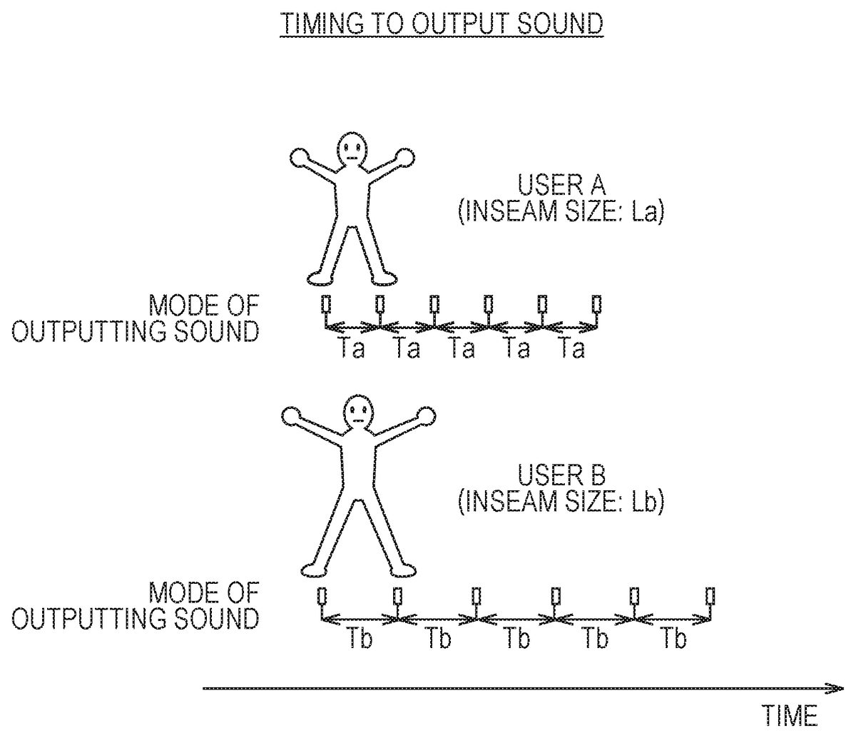
In at least one embodiment of this disclosure, footfalls are output at intervals of a time Ta in accordance with input for movement of a user A in the virtual space. Footfalls are output at intervals of a time Tb in accordance with input for movement of the user B in the virtual space. The computer updates the field-of-view image displayed on a head-mounted device, and further, outputs footfalls at intervals of time that is based on setting of the physical size of the user of the head-mounted device.
Description
DETAILED DESCRIPTION Now, with reference to the drawings, embodiments of this technical idea are described in detail. In the following description, like components are denoted by like reference symbols. The same applies to the names and functions of those components. Therefore, detailed description of those components is not repeated. In one or more embodiments described in this disclosure, components of respective embodiments can be combined with each other, and the combination also serves as a part of the embodiments described in this disclosure. [Configuration of HMD System] With reference toFIG. 1, a configuration of a head-mounted device (HMD) system100is described.FIG. 1is a diagram of a system100including a head-mounted display (HMD) according to at least one embodiment of this disclosure. The system100is usable for household use or for professional use. The system100includes a server600, HMD sets110A,110B,110C, and110D, an external device700, and a network2. Each of the HMD sets110A,110B,110C, and110D is capable of independently communicating to/from the server600or the external device700via the network2. In some instances, the HMD sets110A,110B,110C, and110D are also collectively referred to as “HMD set110”. The number of HMD sets110constructing the HMD system100is not limited to four, but may be three or less, or five or more. The HMD set110includes an HMD120, a computer200, an HMD sensor410, a display430, and a controller300. The HMD120includes a monitor130, an eye gaze sensor140, a first camera150, a second camera160, a microphone170, and a speaker180. In at least one embodiment, the controller300includes a motion sensor420. In at least one aspect, the computer200is connected to the network2, for example, the Internet, and is able to communicate to/from the server600or other computers connected to the network2in a wired or wireless manner. Examples of the other computers include a computer of another HMD set110or the external device700. In at least one aspect, the HMD120includes a sensor190instead ...
DETAILED DESCRIPTION
Now, with reference to the drawings, embodiments of this technical idea are described in detail. In the following description, like components are denoted by like reference symbols. The same applies to the names and functions of those components. Therefore, detailed description of those components is not repeated. In one or more embodiments described in this disclosure, components of respective embodiments can be combined with each other, and the combination also serves as a part of the embodiments described in this disclosure.
[Configuration of HMD System]
With reference toFIG. 1, a configuration of a head-mounted device (HMD) system100is described.FIG. 1is a diagram of a system100including a head-mounted display (HMD) according to at least one embodiment of this disclosure. The system100is usable for household use or for professional use.
The system100includes a server600, HMD sets110A,110B,110C, and110D, an external device700, and a network2. Each of the HMD sets110A,110B,110C, and110D is capable of independently communicating to/from the server600or the external device700via the network2. In some instances, the HMD sets110A,110B,110C, and110D are also collectively referred to as “HMD set110”. The number of HMD sets110constructing the HMD system100is not limited to four, but may be three or less, or five or more. The HMD set110includes an HMD120, a computer200, an HMD sensor410, a display430, and a controller300. The HMD120includes a monitor130, an eye gaze sensor140, a first camera150, a second camera160, a microphone170, and a speaker180. In at least one embodiment, the controller300includes a motion sensor420.
In at least one aspect, the computer200is connected to the network2, for example, the Internet, and is able to communicate to/from the server600or other computers connected to the network2in a wired or wireless manner. Examples of the other computers include a computer of another HMD set110or the external device700. In at least one aspect, the HMD120includes a sensor190instead of the HMD sensor410. In at least one aspect, the HMD120includes both sensor190and the HMD sensor410.
The HMD120is wearable on a head of a user5to display a virtual space to the user5during operation. More specifically, in at least one embodiment, the HMD120displays each of a right-eye image and a left-eye image on the monitor130. Each eye of the user5is able to visually recognize a corresponding image from the right-eye image and the left-eye image so that the user5may recognize a three-dimensional image based on the parallax of both of the user's the eyes. In at least one embodiment, the HMD120includes any one of a so-called head-mounted display including a monitor or a head-mounted device capable of mounting a smartphone or other terminals including a monitor.
The monitor130is implemented as, for example, a non-transmissive display device. In at least one aspect, the monitor130is arranged on a main body of the HMD120so as to be positioned in front of both the eyes of the user5. Therefore, when the user5is able to visually recognize the three-dimensional image displayed by the monitor130, the user5is immersed in the virtual space. In at least one aspect, the virtual space includes, for example, a background, objects that are operable by the user5, or menu images that are selectable by the user5. In at least one aspect, the monitor130is implemented as a liquid crystal monitor or an organic electroluminescence (EL) monitor included in a so-called smartphone or other information display terminals.
In at least one aspect, the monitor130is implemented as a transmissive display device. In this case, the user5is able to see through the HMD120covering the eyes of the user5, for example, smartglasses. In at least one embodiment, the transmissive monitor130is configured as a temporarily non-transmissive display device through adjustment of a transmittance thereof. In at least one embodiment, the monitor130is configured to display a real space and a part of an image constructing the virtual space simultaneously. For example, in at least one embodiment, the monitor130displays an image of the real space captured by a camera mounted on the HMD120, or may enable recognition of the real space by setting the transmittance of a part the monitor130sufficiently high to permit the user5to see through the HMD120.
In at least one aspect, the monitor130includes a sub-monitor for displaying a right-eye image and a sub-monitor for displaying a left-eye image. In at least one aspect, the monitor130is configured to integrally display the right-eye image and the left-eye image. In this case, the monitor130includes a high-speed shutter. The high-speed shutter operates so as to alternately display the right-eye image to the right of the user5and the left-eye image to the left eye of the user5, so that only one of the user's5eyes is able to recognize the image at any single point in time.
In at least one aspect, the HMD120includes a plurality of light sources (not shown). Each light source is implemented by, for example, a light emitting diode (LED) configured to emit an infrared ray. The HMD sensor410has a position tracking function for detecting the motion of the HMD120. More specifically, the HMD sensor410reads a plurality of infrared rays emitted by the HMD120to detect the position and the inclination of the HMD120in the real space.
In at least one aspect, the HMD sensor410is implemented by a camera. In at least one aspect, the HMD sensor410uses image information of the HMD120output from the camera to execute image analysis processing, to thereby enable detection of the position and the inclination of the HMD120.
In at least one aspect, the HMD120includes the sensor190instead of, or in addition to, the HMD sensor410as a position detector. In at least one aspect, the HMD120uses the sensor190to detect the position and the inclination of the HMD120. For example, in at least one embodiment, when the sensor190is an angular velocity sensor, a geomagnetic sensor, or an acceleration sensor, the HMD120uses any or all of those sensors instead of (or in addition to) the HMD sensor410to detect the position and the inclination of the HMD120. As an example, when the sensor190is an angular velocity sensor, the angular velocity sensor detects over time the angular velocity about each of three axes of the HMD120in the real space. The HMD120calculates a temporal change of the angle about each of the three axes of the HMD120based on each angular velocity, and further calculates an inclination of the HMD120based on the temporal change of the angles.
The eye gaze sensor140detects a direction in which the lines of sight of the right eye and the left eye of the user5are directed. That is, the eye gaze sensor140detects the line of sight of the user5. The direction of the line of sight is detected by, for example, a known eye tracking function. The eye gaze sensor140is implemented by a sensor having the eye tracking function. In at least one aspect, the eye gaze sensor140includes a right-eye sensor and a left-eye sensor. In at least one embodiment, the eye gaze sensor140is, for example, a sensor configured to irradiate the right eye and the left eye of the user5with an infrared ray, and to receive reflection light from the cornea and the iris with respect to the irradiation light, to thereby detect a rotational angle of each of the user's5eyeballs. In at least one embodiment, the eye gaze sensor140detects the line of sight of the user5based on each detected rotational angle.
The first camera150photographs a lower part of a face of the user5. More specifically, the first camera150photographs, for example, the nose or mouth of the user5. The second camera160photographs, for example, the eyes and eyebrows of the user5. A side of a casing of the HMD120on the user5side is defined as an interior side of the HMD120, and a side of the casing of the HMD120on a side opposite to the user5side is defined as an exterior side of the HMD120. In at least one aspect, the first camera150is arranged on an exterior side of the HMD120, and the second camera160is arranged on an interior side of the HMD120. Images generated by the first camera150and the second camera160are input to the computer200. In at least one aspect, the first camera150and the second camera160are implemented as a single camera, and the face of the user5is photographed with this single camera.
The microphone170converts an utterance of the user5into a voice signal (electric signal) for output to the computer200. The speaker180converts the voice signal into a voice for output to the user5. In at least one embodiment, the speaker180converts other signals into audio information provided to the user5. In at least one aspect, the HMD120includes earphones in place of the speaker180.
The controller300is connected to the computer200through wired or wireless communication. The controller300receives input of a command from the user5to the computer200. In at least one aspect, the controller300is held by the user5. In at least one aspect, the controller300is mountable to the body or a part of the clothes of the user5. In at least one aspect, the controller300is configured to output at least any one of a vibration, a sound, or light based on the signal transmitted from the computer200. In at least one aspect, the controller300receives from the user5an operation for controlling the position and the motion of an object arranged in the virtual space.
In at least one aspect, the controller300includes a plurality of light sources. Each light source is implemented by, for example, an LED configured to emit an infrared ray. The HMD sensor410has a position tracking function. In this case, the HMD sensor410reads a plurality of infrared rays emitted by the controller300to detect the position and the inclination of the controller300in the real space. In at least one aspect, the HMD sensor410is implemented by a camera. In this case, the HMD sensor410uses image information of the controller300output from the camera to execute image analysis processing, to thereby enable detection of the position and the inclination of the controller300.
In at least one aspect, the motion sensor420is mountable on the hand of the user5to detect the motion of the hand of the user5. For example, the motion sensor420detects a rotational speed, a rotation angle, and the number of rotations of the hand. The detected signal is transmitted to the computer200. The motion sensor420is provided to, for example, the controller300. In at least one aspect, the motion sensor420is provided to, for example, the controller300capable of being held by the user5. In at least one aspect, to help prevent accidently release of the controller300in the real space, the controller300is mountable on an object like a glove-type object that does not easily fly away by being worn on a hand of the user5. In at least one aspect, a sensor that is not mountable on the user5detects the motion of the hand of the user5. For example, a signal of a camera that photographs the user5may be input to the computer200as a signal representing the motion of the user5. As at least one example, the motion sensor420and the computer200are connected to each other through wired or wireless communication. In the case of wireless communication, the communication mode is not particularly limited, and for example, Bluetooth (trademark) or other known communication methods are usable.
The display430displays an image similar to an image displayed on the monitor130. With this, a user other than the user5wearing the HMD120can also view an image similar to that of the user5. An image to be displayed on the display430is not required to be a three-dimensional image, but may be a right-eye image or a left-eye image. For example, a liquid crystal display or an organic EL monitor may be used as the display430.
In at least one embodiment, the server600transmits a program to the computer200. In at least one aspect, the server600communicates to/from another computer200for providing virtual reality to the HMD120used by another user. For example, when a plurality of users play a participatory game, for example, in an amusement facility, each computer200communicates to/from another computer200via the server600with a signal that is based on the motion of each user, to thereby enable the plurality of users to enjoy a common game in the same virtual space. Each computer200may communicate to/from another computer200with the signal that is based on the motion of each user without intervention of the server600.
The external device700is any suitable device as long as the external device700is capable of communicating to/from the computer200. The external device700is, for example, a device capable of communicating to/from the computer200via the network2, or is a device capable of directly communicating to/from the computer200by near field communication or wired communication. Peripheral devices such as a smart device, a personal computer (PC), or the computer200are usable as the external device700, in at least one embodiment, but the external device700is not limited thereto.
[Hardware Configuration of Computer]
With reference toFIG. 2, the computer200in at least one embodiment is described.FIG. 2is a block diagram of a hardware configuration of the computer200according to at least one embodiment. The computer200includes, a processor210, a memory220, a storage230, an input/output interface240, and a communication interface250. Each component is connected to a bus260. In at least one embodiment, at least one of the processor210, the memory220, the storage230, the input/output interface240or the communication interface250is part of a separate structure and communicates with other components of computer200through a communication path other than the bus260.
The processor210executes a series of commands included in a program stored in the memory220or the storage230based on a signal transmitted to the computer200or in response to a condition determined in advance. In at least one aspect, the processor210is implemented as a central processing unit (CPU), a graphics processing unit (GPU), a micro-processor unit (MPU), a field-programmable gate array (FPGA), or other devices.
The memory220temporarily stores programs and data. The programs are loaded from, for example, the storage230. The data includes data input to the computer200and data generated by the processor210. In at least one aspect, the memory220is implemented as a random access memory (RAM) or other volatile memories.
The storage230permanently stores programs and data. In at least one embodiment, the storage230stores programs and data for a period of time longer than the memory220, but not permanently. The storage230is implemented as, for example, a read-only memory (ROM), a hard disk device, a flash memory, or other non-volatile storage devices. The programs stored in the storage230include programs for providing a virtual space in the system100, simulation programs, game programs, user authentication programs, and programs for implementing communication to/from other computers200. The data stored in the storage230includes data and objects for defining the virtual space.
In at least one aspect, the storage230is implemented as a removable storage device like a memory card. In at least one aspect, a configuration that uses programs and data stored in an external storage device is used instead of the storage230built into the computer200. With such a configuration, for example, in a situation in which a plurality of HMD systems100are used, for example in an amusement facility, the programs and the data are collectively updated.
The input/output interface240allows communication of signals among the HMD120, the HMD sensor410, the motion sensor420, and the display430. The monitor130, the eye gaze sensor140, the first camera150, the second camera160, the microphone170, and the speaker180included in the HMD120may communicate to/from the computer200via the input/output interface240of the HMD120. In at least one aspect, the input/output interface240is implemented with use of a universal serial bus (USB), a digital visual interface (DVI), a high-definition multimedia interface (HDMI) (trademark), or other terminals. The input/output interface240is not limited to the specific examples described above.
In at least one aspect, the input/output interface240further communicates to/from the controller300. For example, the input/output interface240receives input of a signal output from the controller300and the motion sensor420. In at least one aspect, the input/output interface240transmits a command output from the processor210to the controller300. The command instructs the controller300to, for example, vibrate, output a sound, or emit light. When the controller300receives the command, the controller300executes anyone of vibration, sound output, and light emission in accordance with the command.
The communication interface250is connected to the network2to communicate to/from other computers (e.g., server600) connected to the network2. In at least one aspect, the communication interface250is implemented as, for example, a local area network (LAN), other wired communication interfaces, wireless fidelity (Wi-Fi), Bluetooth®, near field communication (NFC), or other wireless communication interfaces. The communication interface250is not limited to the specific examples described above.
In at least one aspect, the processor210accesses the storage230and loads one or more programs stored in the storage230to the memory220to execute a series of commands included in the program. In at least one embodiment, the one or more programs includes an operating system of the computer200, an application program for providing a virtual space, and/or game software that is executable in the virtual space. The processor210transmits a signal for providing a virtual space to the HMD120via the input/output interface240. The HMD120displays a video on the monitor130based on the signal.
InFIG. 2, the computer200is outside of the HMD120, but in at least one aspect, the computer200is integral with the HMD120. As an example, a portable information communication terminal (e.g., smartphone) including the monitor130functions as the computer200in at least one embodiment.
In at least one embodiment, the computer200is used in common with a plurality of HMDs120. With such a configuration, for example, the computer200is able to provide the same virtual space to a plurality of users, and hence each user can enjoy the same application with other users in the same virtual space.
According to at least one embodiment of this disclosure, in the system100, a real coordinate system is set in advance. The real coordinate system is a coordinate system in the real space. The real coordinate system has three reference directions (axes) that are respectively parallel to a vertical direction, a horizontal direction orthogonal to the vertical direction, and a front-rear direction orthogonal to both of the vertical direction and the horizontal direction in the real space. The horizontal direction, the vertical direction (up-down direction), and the front-rear direction in the real coordinate system are defined as an x axis, a y axis, and a z axis, respectively. More specifically, the x axis of the real coordinate system is parallel to the horizontal direction of the real space, the y axis thereof is parallel to the vertical direction of the real space, and the z axis thereof is parallel to the front-rear direction of the real space.
In at least one aspect, the HMD sensor410includes an infrared sensor. When the infrared sensor detects the infrared ray emitted from each light source of the HMD120, the infrared sensor detects the presence of the HMD120. The HMD sensor410further detects the position and the inclination (direction) of the HMD120in the real space, which corresponds to the motion of the user5wearing the HMD120, based on the value of each point (each coordinate value in the real coordinate system). In more detail, the HMD sensor410is able to detect the temporal change of the position and the inclination of the HMD120with use of each value detected over time.
Each inclination of the HMD120detected by the HMD sensor410corresponds to an inclination about each of the three axes of the HMD120in the real coordinate system. The HMD sensor410sets a uvw visual-field coordinate system to the HMD120based on the inclination of the HMD120in the real coordinate system. The uvw visual-field coordinate system set to the HMD120corresponds to a point-of-view coordinate system used when the user5wearing the HMD120views an object in the virtual space.
[Uvw Visual-Field Coordinate System]
With reference toFIG. 3, the uvw visual-field coordinate system is described.FIG. 3is a diagram of a uvw visual-field coordinate system to be set for the HMD120according to at least one embodiment of this disclosure. The HMD sensor410detects the position and the inclination of the HMD120in the real coordinate system when the HMD120is activated. The processor210sets the uvw visual-field coordinate system to the HMD120based on the detected values.
InFIG. 3, the HMD120sets the three-dimensional uvw visual-field coordinate system defining the head of the user5wearing the HMD120as a center (origin). More specifically, the HMD120sets three directions newly obtained by inclining the horizontal direction, the vertical direction, and the front-rear direction (x axis, y axis, and z axis), which define the real coordinate system, about the respective axes by the inclinations about the respective axes of the HMD120in the real coordinate system, as a pitch axis (u axis), a yaw axis (v axis), and a roll axis (w axis) of the uvw visual-field coordinate system in the HMD120.
In at least one aspect, when the user5wearing the HMD120is standing (or sitting) upright and is visually recognizing the front side, the processor210sets the uvw visual-field coordinate system that is parallel to the real coordinate system to the HMD120. In this case, the horizontal direction (x axis), the vertical direction (y axis), and the front-rear direction (z axis) of the real coordinate system directly match the pitch axis (u axis), the yaw axis (v axis), and the roll axis (w axis) of the uvw visual-field coordinate system in the HMD120, respectively.
After the uvw visual-field coordinate system is set to the HMD120, the HMD sensor410is able to detect the inclination of the HMD120in the set uvw visual-field coordinate system based on the motion of the HMD120. In this case, the HMD sensor410detects, as the inclination of the HMD120, each of a pitch angle (θu), a yaw angle (θv), and a roll angle (θw) of the HMD120in the uvw visual-field coordinate system. The pitch angle (θu) represents an inclination angle of the HMD120about the pitch axis in the uvw visual-field coordinate system. The yaw angle (θv) represents an inclination angle of the HMD120about the yaw axis in the uvw visual-field coordinate system. The roll angle (θw) represents an inclination angle of the HMD120about the roll axis in the uvw visual-field coordinate system.
The HMD sensor410sets, to the HMD120, the uvw visual-field coordinate system of the HMD120obtained after the movement of the HMD120based on the detected inclination angle of the HMD120. The relationship between the HMD120and the uvw visual-field coordinate system of the HMD120is constant regardless of the position and the inclination of the HMD120. When the position and the inclination of the HMD120change, the position and the inclination of the uvw visual-field coordinate system of the HMD120in the real coordinate system change in synchronization with the change of the position and the inclination.
In at least one aspect, the HMD sensor410identifies the position of the HMD120in the real space as a position relative to the HMD sensor410based on the light intensity of the infrared ray or a relative positional relationship between a plurality of points (e.g., distance between points), which is acquired based on output from the infrared sensor. In at least one aspect, the processor210determines the origin of the uvw visual-field coordinate system of the HMD120in the real space (real coordinate system) based on the identified relative position.
[Virtual Space]
With reference toFIG. 4, the virtual space is further described.FIG. 4is a diagram of a mode of expressing a virtual space11according to at least one embodiment of this disclosure. The virtual space11has a structure with an entire celestial sphere shape covering a center12in all 360-degree directions. InFIG. 4, for the sake of clarity, only the upper-half celestial sphere of the virtual space11is included. Each mesh section is defined in the virtual space11. The position of each mesh section is defined in advance as coordinate values in an XYZ coordinate system, which is a global coordinate system defined in the virtual space11. The computer200associates each partial image forming a panorama image13(e.g., still image or moving image) that is developed in the virtual space11with each corresponding mesh section in the virtual space11.
In at least one aspect, in the virtual space11, the XYZ coordinate system having the center12as the origin is defined. The XYZ coordinate system is, for example, parallel to the real coordinate system. The horizontal direction, the vertical direction (up-down direction), and the front-rear direction of the XYZ coordinate system are defined as an X axis, a Y axis, and a Z axis, respectively. Thus, the X axis (horizontal direction) of the XYZ coordinate system is parallel to the x axis of the real coordinate system, the Y axis (vertical direction) of the XYZ coordinate system is parallel to the y axis of the real coordinate system, and the Z axis (front-rear direction) of the XYZ coordinate system is parallel to the z axis of the real coordinate system.
When the HMD120is activated, that is, when the HMD120is in an initial state, a virtual camera14is arranged at the center12of the virtual space11. In at least one embodiment, the virtual camera14is offset from the center12in the initial state. In at least one aspect, the processor210displays on the monitor130of the HMD120an image photographed by the virtual camera14. In synchronization with the motion of the HMD120in the real space, the virtual camera14similarly moves in the virtual space11. With this, the change in position and direction of the HMD120in the real space is reproduced similarly in the virtual space11.
The uvw visual-field coordinate system is defined in the virtual camera14similarly to the case of the HMD120. The uvw visual-field coordinate system of the virtual camera14in the virtual space11is defined to be synchronized with the uvw visual-field coordinate system of the HMD120in the real space (real coordinate system). Therefore, when the inclination of the HMD120changes, the inclination of the virtual camera14also changes in synchronization therewith. The virtual camera14can also move in the virtual space11in synchronization with the movement of the user5wearing the HMD120in the real space.
The processor210of the computer200defines a field-of-view region15in the virtual space11based on the position and inclination (reference line of sight16) of the virtual camera14. The field-of-view region15corresponds to, of the virtual space11, the region that is visually recognized by the user5wearing the HMD120. That is, the position of the virtual camera14determines a point of view of the user5in the virtual space11.
The line of sight of the user5detected by the eye gaze sensor140is a direction in the point-of-view coordinate system obtained when the user5visually recognizes an object. The uvw visual-field coordinate system of the HMD120is equal to the point-of-view coordinate system used when the user5visually recognizes the monitor130. The uvw visual-field coordinate system of the virtual camera14is synchronized with the uvw visual-field coordinate system of the HMD120. Therefore, in the system100in at least one aspect, the line of sight of the user5detected by the eye gaze sensor140can be regarded as the line of sight of the user5in the uvw visual-field coordinate system of the virtual camera14.
[User's Line of Sight]
With reference toFIG. 5, determination of the line of sight of the user5is described.FIG. 5is a plan view diagram of the head of the user5wearing the HMD120according to at least one embodiment of this disclosure.
In at least one aspect, the eye gaze sensor140detects lines of sight of the right eye and the left eye of the user5. In at least one aspect, when the user5is looking at a near place, the eye gaze sensor140detects lines of sight R1and L1. In at least one aspect, when the user5is looking at a far place, the eye gaze sensor140detects lines of sight R2and L2. In this case, the angles formed by the lines of sight R2and L2with respect to the roll axis w are smaller than the angles formed by the lines of sight R1and L1with respect to the roll axis w. The eye gaze sensor140transmits the detection results to the computer200.
When the computer200receives the detection values of the lines of sight R1and L1from the eye gaze sensor140as the detection results of the lines of sight, the computer200identifies a point of gaze N1being an intersection of both the lines of sight R1and L1based on the detection values. Meanwhile, when the computer200receives the detection values of the lines of sight R2and L2from the eye gaze sensor140, the computer200identifies an intersection of both the lines of sight R2and L2as the point of gaze. The computer200identifies a line of sight N0of the user5based on the identified point of gaze N1. The computer200detects, for example, an extension direction of a straight line that passes through the point of gaze N1and a midpoint of a straight line connecting a right eye R and a left eye L of the user5to each other as the line of sight N0. The line of sight N0is a direction in which the user5actually directs his or her lines of sight with both eyes. The line of sight N0corresponds to a direction in which the user5actually directs his or her lines of sight with respect to the field-of-view region15.
In at least one aspect, the system100includes a television broadcast reception tuner. With such a configuration, the system100is able to display a television program in the virtual space11.
In at least one aspect, the HMD system100includes a communication circuit for connecting to the Internet or has a verbal communication function for connecting to a telephone line or a cellular service.
[Field-Of-View Region]
With reference toFIG. 6andFIG. 7, the field-of-view region15is described.FIG. 6is a diagram of a YZ cross section obtained by viewing the field-of-view region15from an X direction in the virtual space11.FIG. 7is a diagram of an XZ cross section obtained by viewing the field-of-view region15from a Y direction in the virtual space11.
InFIG. 6, the field-of-view region15in the YZ cross section includes a region18. The region18is defined by the position of the virtual camera14, the reference line of sight16, and the YZ cross section of the virtual space11. The processor210defines a range of a polar angle α from the reference line of sight16serving as the center in the virtual space as the region18.
InFIG. 7, the field-of-view region15in the XZ cross section includes a region19. The region19is defined by the position of the virtual camera14, the reference line of sight16, and the XZ cross section of the virtual space11. The processor210defines a range of an azimuth β from the reference line of sight16serving as the center in the virtual space11as the region19. The polar angle α and β are determined in accordance with the position of the virtual camera14and the inclination (direction) of the virtual camera14.
In at least one aspect, the system100causes the monitor130to display a field-of-view image17based on the signal from the computer200, to thereby provide the field of view in the virtual space11to the user5. The field-of-view image17corresponds to a part of the panorama image13, which corresponds to the field-of-view region15. When the user5moves the HMD120worn on his or her head, the virtual camera14is also moved in synchronization with the movement. As a result, the position of the field-of-view region15in the virtual space11is changed. With this, the field-of-view image17displayed on the monitor130is updated to an image of the panorama image13, which is superimposed on the field-of-view region15synchronized with a direction in which the user5faces in the virtual space11. The user5can visually recognize a desired direction in the virtual space11.
In this way, the inclination of the virtual camera14corresponds to the line of sight of the user5(reference line of sight16) in the virtual space11, and the position at which the virtual camera14is arranged corresponds to the point of view of the user5in the virtual space11. Therefore, through the change of the position or inclination of the virtual camera14, the image to be displayed on the monitor130is updated, and the field of view of the user5is moved.
While the user5is wearing the HMD120(having a non-transmissive monitor130), the user5can visually recognize only the panorama image13developed in the virtual space11without visually recognizing the real world. Therefore, the system100provides a high sense of immersion in the virtual space11to the user5.
In at least one aspect, the processor210moves the virtual camera14in the virtual space11in synchronization with the movement in the real space of the user5wearing the HMD120. In this case, the processor210identifies an image region to be projected on the monitor130of the HMD120(field-of-view region15) based on the position and the direction of the virtual camera14in the virtual space11.
In at least one aspect, the virtual camera14includes two virtual cameras, that is, a virtual camera for providing a right-eye image and a virtual camera for providing a left-eye image. An appropriate parallax is set for the two virtual cameras so that the user5is able to recognize the three-dimensional virtual space11. In at least one aspect, the virtual camera14is implemented by a single virtual camera. In this case, a right-eye image and a left-eye image may be generated from an image acquired by the single virtual camera. In at least one embodiment, the virtual camera14is assumed to include two virtual cameras, and the roll axes of the two virtual cameras are synthesized so that the generated roll axis (w) is adapted to the roll axis (w) of the HMD120.
[Controller]
An example of the controller300is described with reference toFIG. 8AandFIG. 8B.FIG. 8Ais a diagram of a schematic configuration of a controller according to at least one embodiment of this disclosure.FIG. 8Bis a diagram of a coordinate system to be set for a hand of a user holding the controller according to at least one embodiment of this disclosure.
In at least one aspect, the controller300includes a right controller300R and a left controller (not shown). InFIG. 8Aonly right controller300R is shown for the sake of clarity. The right controller300R is operable by the right hand of the user5. The left controller is operable by the left hand of the user5. In at least one aspect, the right controller300R and the left controller are symmetrically configured as separate devices. Therefore, the user5can freely move his or her right hand holding the right controller300R and his or her left hand holding the left controller. In at least one aspect, the controller300may be an integrated controller configured to receive an operation performed by both the right and left hands of the user5. The right controller300R is now described.
The right controller300R includes a grip310, a frame320, and a top surface330. The grip310is configured so as to be held by the right hand of the user5. For example, the grip310may be held by the palm and three fingers (e.g., middle finger, ring finger, and small finger) of the right hand of the user5.
The grip310includes buttons340and350and the motion sensor420. The button340is arranged on a side surface of the grip310, and receives an operation performed by, for example, the middle finger of the right hand. The button350is arranged on a front surface of the grip310, and receives an operation performed by, for example, the index finger of the right hand. In at least one aspect, the buttons340and350are configured as trigger type buttons. The motion sensor420is built into the casing of the grip310. When a motion of the user5can be detected from the surroundings of the user5by a camera or other device. In at least one embodiment, the grip310does not include the motion sensor420.
The frame320includes a plurality of infrared LEDs360arranged in a circumferential direction of the frame320. The infrared LEDs360emit, during execution of a program using the controller300, infrared rays in accordance with progress of the program. The infrared rays emitted from the infrared LEDs360are usable to independently detect the position and the posture (inclination and direction) of each of the right controller300R and the left controller. InFIG. 8A, the infrared LEDs360are shown as being arranged in two rows, but the number of arrangement rows is not limited to that illustrated inFIG. 8. In at least one embodiment, the infrared LEDs360are arranged in one row or in three or more rows. In at least one embodiment, the infrared LEDs360are arranged in a pattern other than rows.
The top surface330includes buttons370and380and an analog stick390. The buttons370and380are configured as push type buttons. The buttons370and380receive an operation performed by the thumb of the right hand of the user5. In at least one aspect, the analog stick390receives an operation performed in any direction of 360 degrees from an initial position (neutral position). The operation includes, for example, an operation for moving an object arranged in the virtual space11.
In at least one aspect, each of the right controller300R and the left controller includes a battery for driving the infrared ray LEDs360and other members. The battery includes, for example, a rechargeable battery, a button battery, a dry battery, but the battery is not limited thereto. In at least one aspect, the right controller300R and the left controller are connectable to, for example, a USB interface of the computer200. In at least one embodiment, the right controller300R and the left controller do not include a battery.
InFIG. 8AandFIG. 8B, for example, a yaw direction, a roll direction, and a pitch direction are defined with respect to the right hand of the user5. A direction of an extended thumb is defined as the yaw direction, a direction of an extended index finger is defined as the roll direction, and a direction perpendicular to a plane defined by the yaw-direction axis and the roll-direction axis when the user5extends his or her thumb and index finger is defined as the pitch direction.
[Hardware Configuration of Server]
With reference toFIG. 9, the server600in at least one embodiment is described.FIG. 9is a block diagram of a hardware configuration of the server600according to at least one embodiment of this disclosure. The server600includes a processor610, a memory620, a storage630, an input/output interface640, and a communication interface650. Each component is connected to a bus660. In at least one embodiment, at least one of the processor610, the memory620, the storage630, the input/output interface640or the communication interface650is part of a separate structure and communicates with other components of server600through a communication path other than the bus660.
The processor610executes a series of commands included in a program stored in the memory620or the storage630based on a signal transmitted to the server600or on satisfaction of a condition determined in advance. In at least one aspect, the processor610is implemented as a central processing unit (CPU), a graphics processing unit (GPU), a micro processing unit (MPU), a field-programmable gate array (FPGA), or other devices.
The memory620temporarily stores programs and data. The programs are loaded from, for example, the storage630. The data includes data input to the server600and data generated by the processor610. In at least one aspect, the memory620is implemented as a random access memory (RAM) or other volatile memories.
The storage630permanently stores programs and data. In at least one embodiment, the storage630stores programs and data for a period of time longer than the memory620, but not permanently. The storage630is implemented as, for example, a read-only memory (ROM), a hard disk device, a flash memory, or other non-volatile storage devices. The programs stored in the storage630include programs for providing a virtual space in the system100, simulation programs, game programs, user authentication programs, and programs for implementing communication to/from other computers200or servers600. The data stored in the storage630may include, for example, data and objects for defining the virtual space.
In at least one aspect, the storage630is implemented as a removable storage device like a memory card. In at least one aspect, a configuration that uses programs and data stored in an external storage device is used instead of the storage630built into the server600. With such a configuration, for example, in a situation in which a plurality of HMD systems100are used, for example, as in an amusement facility, the programs and the data are collectively updated.
The input/output interface640allows communication of signals to/from an input/output device. In at least one aspect, the input/output interface640is implemented with use of a USB, a DVI, an HDMI, or other terminals. The input/output interface640is not limited to the specific examples described above.
The communication interface650is connected to the network2to communicate to/from the computer200connected to the network2. In at least one aspect, the communication interface650is implemented as, for example, a LAN, other wired communication interfaces, Wi-Fi, Bluetooth, NFC, or other wireless communication interfaces. The communication interface650is not limited to the specific examples described above.
In at least one aspect, the processor610accesses the storage630and loads one or more programs stored in the storage630to the memory620to execute a series of commands included in the program. In at least one embodiment, the one or more programs include, for example, an operating system of the server600, an application program for providing a virtual space, and game software that can be executed in the virtual space. In at least one embodiment, the processor610transmits a signal for providing a virtual space to the HMD device110to the computer200via the input/output interface640.
[Control Device of HMD]
With reference toFIG. 10, the control device of the HMD120is described. According to at least one embodiment of this disclosure, the control device is implemented by the computer200having a known configuration.FIG. 10is a block diagram of the computer200according to at least one embodiment of this disclosure.FIG. 10includes a module configuration of the computer200.
InFIG. 10, the computer200includes a control module510, a rendering module520, a memory module530, and a communication control module540. In at least one aspect, the control module510and the rendering module520are implemented by the processor210. In at least one aspect, a plurality of processors210function as the control module510and the rendering module520. The memory module530is implemented by the memory220or the storage230. The communication control module540is implemented by the communication interface250.
The control module510controls the virtual space11provided to the user5. The control module510defines the virtual space11in the HMD system100using virtual space data representing the virtual space11. The virtual space data is stored in, for example, the memory module530. In at least one embodiment, the control module510generates virtual space data. In at least one embodiment, the control module510acquires virtual space data from, for example, the server600.
The control module510arranges objects in the virtual space11using object data representing objects. The object data is stored in, for example, the memory module530. In at least one embodiment, the control module510generates virtual space data. In at least one embodiment, the control module510acquires virtual space data from, for example, the server600. In at least one embodiment, the objects include, for example, an avatar object of the user5, character objects, operation objects, for example, a virtual hand to be operated by the controller300, and forests, mountains, other landscapes, streetscapes, or animals to be arranged in accordance with the progression of the story of the game.
The control module510arranges an avatar object of the user5of another computer200, which is connected via the network2, in the virtual space11. In at least one aspect, the control module510arranges an avatar object of the user5in the virtual space11. In at least one aspect, the control module510arranges an avatar object simulating the user5in the virtual space11based on an image including the user5. In at least one aspect, the control module510arranges an avatar object in the virtual space11, which is selected by the user5from among a plurality of types of avatar objects (e.g., objects simulating animals or objects of deformed humans).
The control module510identifies an inclination of the HMD120based on output of the HMD sensor410. In at least one aspect, the control module510identifies an inclination of the HMD120based on output of the sensor190functioning as a motion sensor. The control module510detects parts (e.g., mouth, eyes, and eyebrows) forming the face of the user5from a face image of the user5generated by the first camera150and the second camera160. The control module510detects a motion (shape) of each detected part.
The control module510detects a line of sight of the user5in the virtual space11based on a signal from the eye gaze sensor140. The control module510detects a point-of-view position (coordinate values in the XYZ coordinate system) at which the detected line of sight of the user5and the celestial sphere of the virtual space11intersect with each other. More specifically, the control module510detects the point-of-view position based on the line of sight of the user5defined in the uvw coordinate system and the position and the inclination of the virtual camera14. The control module510transmits the detected point-of-view position to the server600. In at least one aspect, the control module510is configured to transmit line-of-sight information representing the line of sight of the user5to the server600. In such a case, the control module510may calculate the point-of-view position based on the line-of-sight information received by the server600.
The control module510translates a motion of the HMD120, which is detected by the HMD sensor410, in an avatar object. For example, the control module510detects inclination of the HMD120, and arranges the avatar object in an inclined manner. The control module510translates the detected motion of face parts in a face of the avatar object arranged in the virtual space11. The control module510receives line-of-sight information of another user5from the server600, and translates the line-of-sight information in the line of sight of the avatar object of another user5. In at least one aspect, the control module510translates a motion of the controller300in an avatar object and an operation object. In this case, the controller300includes, for example, a motion sensor, an acceleration sensor, or a plurality of light emitting elements (e.g., infrared LEDs) for detecting a motion of the controller300.
The control module510arranges, in the virtual space11, an operation object for receiving an operation by the user5in the virtual space11. The user5operates the operation object to, for example, operate an object arranged in the virtual space11. In at least one aspect, the operation object includes, for example, a hand object serving as a virtual hand corresponding to a hand of the user5. In at least one aspect, the control module510moves the hand object in the virtual space11so that the hand object moves in association with a motion of the hand of the user5in the real space based on output of the motion sensor420. In at least one aspect, the operation object may correspond to a hand part of an avatar object.
When one object arranged in the virtual space11collides with another object, the control module510detects the collision. The control module510is able to detect, for example, a timing at which a collision area of one object and a collision area of another object have touched with each other, and performs predetermined processing in response to the detected timing. In at least one embodiment, the control module510detects a timing at which an object and another object, which have been in contact with each other, have moved away from each other, and performs predetermined processing in response to the detected timing. In at least one embodiment, the control module510detects a state in which an object and another object are in contact with each other. For example, when an operation object touches another object, the control module510detects the fact that the operation object has touched the other object, and performs predetermined processing.
In at least one aspect, the control module510controls image display of the HMD120on the monitor130. For example, the control module510arranges the virtual camera14in the virtual space11. The control module510controls the position of the virtual camera14and the inclination (direction) of the virtual camera14in the virtual space11. The control module510defines the field-of-view region15depending on an inclination of the head of the user5wearing the HMD120and the position of the virtual camera14. The rendering module520generates the field-of-view region17to be displayed on the monitor130based on the determined field-of-view region15. The communication control module540outputs the field-of-view region17generated by the rendering module520to the HMD120.
The control module510, which has detected an utterance of the user5using the microphone170from the HMD120, identifies the computer200to which voice data corresponding to the utterance is to be transmitted. The voice data is transmitted to the computer200identified by the control module510. The control module510, which has received voice data from the computer200of another user via the network2, outputs audio information (utterances) corresponding to the voice data from the speaker180.
The memory module530holds data to be used to provide the virtual space11to the user5by the computer200. In at least one aspect, the memory module530stores space information, object information, and user information.
The space information stores one or more templates defined to provide the virtual space11.
The object information stores a plurality of panorama images13forming the virtual space11and object data for arranging objects in the virtual space11. In at least one embodiment, the panorama image13contains a still image and/or a moving image. In at least one embodiment, the panorama image13contains an image in a non-real space and/or an image in the real space. An example of the image in a non-real space is an image generated by computer graphics.
The user information stores a user ID for identifying the user5. The user ID is, for example, an internet protocol (IP) address or a media access control (MAC) address set to the computer200used by the user. In at least one aspect, the user ID is set by the user. The user information stores, for example, a program for causing the computer200to function as the control device of the HMD system100.
The data and programs stored in the memory module530are input by the user5of the HMD120. Alternatively, the processor210downloads the programs or data from a computer (e.g., server600) that is managed by a business operator providing the content, and stores the downloaded programs or data in the memory module530.
In at least one embodiment, the communication control module540communicates to/from the server600or other information communication devices via the network2.
In at least one aspect, the control module510and the rendering module520are implemented with use of, for example, Unity® provided by Unity Technologies. In at least one aspect, the control module510and the rendering module520are implemented by combining the circuit elements for implementing each step of processing.
The processing performed in the computer200is implemented by hardware and software executed by the processor410. In at least one embodiment, the software is stored in advance on a hard disk or other memory module530. In at least one embodiment, the software is stored on a CD-ROM or other computer-readable non-volatile data recording media, and distributed as a program product. In at least one embodiment, the software may is provided as a program product that is downloadable by an information provider connected to the Internet or other networks. Such software is read from the data recording medium by an optical disc drive device or other data reading devices, or is downloaded from the server600or other computers via the communication control module540and then temporarily stored in a storage module. The software is read from the storage module by the processor210, and is stored in a RAM in a format of an executable program. The processor210executes the program.
[Control Structure of HMD System]
With reference toFIG. 11, the control structure of the HMD set110is described.FIG. 11is a sequence chart of processing to be executed by the system100according to at least one embodiment of this disclosure.
InFIG. 11, in Step S1110, the processor210of the computer200serves as the control module510to identify virtual space data and define the virtual space11.
In Step S1120, the processor210initializes the virtual camera14. For example, in a work area of the memory, the processor210arranges the virtual camera14at the center12defined in advance in the virtual space11, and matches the line of sight of the virtual camera14with the direction in which the user5faces.
In Step S1130, the processor210serves as the rendering module520to generate field-of-view image data for displaying an initial field-of-view image. The generated field-of-view image data is output to the HMD120by the communication control module540.
In Step S1132, the monitor130of the HMD120displays the field-of-view image based on the field-of-view image data received from the computer200. The user5wearing the HMD120is able to recognize the virtual space11through visual recognition of the field-of-view image.
In Step S1134, the HMD sensor410detects the position and the inclination of the HMD120based on a plurality of infrared rays emitted from the HMD120. The detection results are output to the computer200as motion detection data.
In Step S1140, the processor210identifies a field-of-view direction of the user5wearing the HMD120based on the position and inclination contained in the motion detection data of the HMD120.
In Step S1150, the processor210executes an application program, and arranges an object in the virtual space11based on a command contained in the application program.
In Step S1160, the controller300detects an operation by the user5based on a signal output from the motion sensor420, and outputs detection data representing the detected operation to the computer200. In at least one aspect, an operation of the controller300by the user5is detected based on an image from a camera arranged around the user5.
In Step S1170, the processor210detects an operation of the controller300by the user5based on the detection data acquired from the controller300.
In Step S1180, the processor210generates field-of-view image data based on the operation of the controller300by the user5. The communication control module540outputs the generated field-of-view image data to the HMD120.
In Step S1190, the HMD120updates a field-of-view image based on the received field-of-view image data, and displays the updated field-of-view image on the monitor130.
[Avatar Object]
With reference toFIG. 12AandFIG. 12B, an avatar object according to at least one embodiment is described.FIG. 12andFIG. 12Bare diagrams of avatar objects of respective users5of the HMD sets110A and110B. In the following, the user of the HMD set110A, the user of the HMD set110B, the user of the HMD set110C, and the user of the HMD set110D are referred to as “user5A”, “user5B”, “user5C”, and “user5D”, respectively. A reference numeral of each component related to the HMD set110A, a reference numeral of each component related to the HMD set110B, a reference numeral of each component related to the HMD set110C, and a reference numeral of each component related to the HMD set110D are appended by A, B, C, and D, respectively. For example, the HMD120A is included in the HMD set110A.
FIG. 12Ais a schematic diagram of HMD systems of several users sharing the virtual space interact using a network according to at least one embodiment of this disclosure. Each HMD120provides the user5with the virtual space11. Computers200A to200D provide the users5A to5D with virtual spaces11A to11D via HMDs120A to120D, respectively. InFIG. 12A, the virtual space11A and the virtual space11B are formed by the same data. In other words, the computer200A and the computer200B share the same virtual space. An avatar object6A of the user5A and an avatar object6B of the user5B are present in the virtual space11A and the virtual space11B. The avatar object6A in the virtual space11A and the avatar object6B in the virtual space11B each wear the HMD120. However, the inclusion of the HMD120A and HMD120B is only for the sake of simplicity of description, and the avatars do not wear the HMD120A and HMD120B in the virtual spaces11A and11B, respectively.
In at least one aspect, the processor210A arranges a virtual camera14A for photographing a field-of-view region17A of the user5A at the position of eyes of the avatar object6A.
FIG. 12Bis a diagram of a field of view of a HMD according to at least one embodiment of this disclosure.FIG. 12(B) corresponds to the field-of-view region17A of the user5A inFIG. 12A. The field-of-view region17A is an image displayed on a monitor130A of the HMD120A. This field-of-view region17A is an image generated by the virtual camera14A. The avatar object6B of the user5B is displayed in the field-of-view region17A. Although not included inFIG. 12B, the avatar object6A of the user5A is displayed in the field-of-view image of the user5B.
In the arrangement inFIG. 12B, the user5A can communicate to/from the user5B via the virtual space11A through conversation. More specifically, voices of the user5A acquired by a microphone170A are transmitted to the HMD120B of the user5B via the server600and output from a speaker180B provided on the HMD120B. Voices of the user5B are transmitted to the HMD120A of the user5A via the server600, and output from a speaker180A provided on the HMD120A.
The processor210A translates an operation by the user5B (operation of HMD120B and operation of controller300B) in the avatar object6B arranged in the virtual space11A. With this, the user5A is able to recognize the operation by the user5B through the avatar object6B.
FIG. 13is a sequence chart of processing to be executed by the system100according to at least one embodiment of this disclosure. InFIG. 13, although the HMD set110D is not included, the HMD set110D operates in a similar manner as the HMD sets110A,110B, and110C. Also in the following description, a reference numeral of each component related to the HMD set110A, a reference numeral of each component related to the HMD set110B, a reference numeral of each component related to the HMD set110C, and a reference numeral of each component related to the HMD set110D are appended by A, B, C, and D, respectively.
In Step S1310A, the processor210A of the HMD set110A acquires avatar information for determining a motion of the avatar object6A in the virtual space11A. This avatar information contains information on an avatar such as motion information, face tracking data, and sound data. The motion information contains, for example, information on a temporal change in position and inclination of the HMD120A and information on a motion of the hand of the user5A, which is detected by, for example, a motion sensor420A. An example of the face tracking data is data identifying the position and size of each part of the face of the user5A. Another example of the face tracking data is data representing motions of parts forming the face of the user5A and line-of-sight data. An example of the sound data is data representing sounds of the user5A acquired by the microphone170A of the HMD120A. In at least one embodiment, the avatar information contains information identifying the avatar object6A or the user5A associated with the avatar object6A or information identifying the virtual space11A accommodating the avatar object6A. An example of the information identifying the avatar object6A or the user5A is a user ID. An example of the information identifying the virtual space11A accommodating the avatar object6A is a room ID. The processor210A transmits the avatar information acquired as described above to the server600via the network2.
In Step S1310B, the processor210B of the HMD set110B acquires avatar information for determining a motion of the avatar object6B in the virtual space11B, and transmits the avatar information to the server600, similarly to the processing of Step S1310A. Similarly, in Step S1310C, the processor210C of the HMD set110C acquires avatar information for determining a motion of the avatar object6C in the virtual space11C, and transmits the avatar information to the server600.
In Step S1320, the server600temporarily stores pieces of player information received from the HMD set110A, the HMD set110B, and the HMD set110C, respectively. The server600integrates pieces of avatar information of all the users (in this example, users5A to5C) associated with the common virtual space11based on, for example, the user IDs and room IDs contained in respective pieces of avatar information. Then, the server600transmits the integrated pieces of avatar information to all the users associated with the virtual space11at a timing determined in advance. In this manner, synchronization processing is executed. Such synchronization processing enables the HMD set110A, the HMD set110B, and the HMD120C to share mutual avatar information at substantially the same timing.
Next, the HMD sets110A to110C execute processing of Step S1330A to Step S1330C, respectively, based on the integrated pieces of avatar information transmitted from the server600to the HMD sets110A to110C. The processing of Step S1330A corresponds to the processing of Step S1180ofFIG. 11.
In Step S1330A, the processor210A of the HMD set110A updates information on the avatar object6B and the avatar object6C of the other users5B and5C in the virtual space11A. Specifically, the processor210A updates, for example, the position and direction of the avatar object6B in the virtual space11based on motion information contained in the avatar information transmitted from the HMD set110B. For example, the processor210A updates the information (e.g., position and direction) on the avatar object6B contained in the object information stored in the memory module530. Similarly, the processor210A updates the information (e.g., position and direction) on the avatar object6C in the virtual space11based on motion information contained in the avatar information transmitted from the HMD set110C.
In Step S1330B, similarly to the processing of Step S1330A, the processor210B of the HMD set110B updates information on the avatar object6A and the avatar object6C of the users5A and5C in the virtual space11B. Similarly, in Step S1330C, the processor210C of the HMD set110C updates information on the avatar object6A and the avatar object6B of the users5A and5B in the virtual space11C.
[Detailed Configuration of Modules]
Now, with reference toFIG. 14, a description is given of details of a module configuration of the computer200.FIG. 14is a block diagram of the detailed configuration of modules of the computer200according to at least one embodiment of this disclosure.
InFIG. 14, the control module510includes a virtual camera control module1421, a field-of-view region determination module1422, a reference-line-of-sight identification module1423, a virtual space definition module1424, a virtual object generation module1425, a hand object control module1426, and a sound control module1427. The rendering module520includes a field-of-view image generation module1429. The memory module530stores space information1431, object information1432, and user information1433.
In at least one aspect, the control module510controls display of an image on the monitor130of the HMD120. The virtual camera control module1421arranges the virtual camera14in the virtual space11, and controls, for example, the behavior and direction of the virtual camera14. The field-of-view region determination module1422defines the field-of-view region15. The field-of-view image generation module1429generates a field-of-view image17to be displayed on the monitor130based on the determined field-of-view region15.
The reference-line-of-sight identification module1423identifies the line of sight of the user5based on the signal from the eye gaze sensor140.
The control module510controls the virtual space11to be provided to the user5. The virtual space definition module1424generates virtual space data representing the virtual space11, to thereby define the virtual space11in the HMD set110.
The virtual object generation module1425generates a target object to be displayed in the virtual space11. As an example, the target objects include an avatar of a user of another HMD set110on the network2and an installation object such as a stage and a screen in an event site. In some examples, the target objects include, for example, landscapes including forests, mountains, and others, and animals, which are displayed in accordance with the progression of the story of the game. Further, in some examples, the target objects include avatars of a partner soldier and an enemy soldier, a construction, objects that are installed in a camp, such as a folding screen and a chair, and horses and tanks to be used for combat, which are displayed in a combat game. Further, in some examples, the target objects includes an object, for example, a vase, which is set to be moved (dropped) by an avatar object and/or a hand object operable by the user colliding with the object, and an enemy object moving toward the avatar object operable by the user. In at least one embodiment of this disclosure, the mode of movement (drop) of an object, for example, the vase, follows calculation of physics. Further, in some examples, the target objects include an object that is set to collide with a floor object by being thrown in the virtual space by input operation of the user and generate sound due to this collision. Further, in some examples, the target objects include an enemy object that is set to be moved toward sound generated by collision between the floor object and the object. When the target object is arranged together with a light source having a relatively suppressed light amount in a virtual space derived from a horror story, the user can be provided with a feeling of fear of moving in darkness.
The hand object control module1426arranges the hand object in the virtual space11. In the following description, the hand object arranged in the virtual space11is also referred to as “virtual hand”. The hand object corresponds to, for example, a right hand or a left hand of the user5holding the controller300. In at least one aspect, the hand object management module1426generates data for arranging a left hand object or a right hand object in the virtual space11. In at least one aspect, the hand object management module1426generates data for indicating motion of a left hand object or a right hand object rotating another object in response to operation of the controller300by the user5. This operation includes, for example, a hand holding a steering wheel represented as an object rotating the steering wheel.
The space information1431stores one or more templates that are defined to provide the virtual space11.
The object information1432stores content to be reproduced in the virtual space11, information for displaying an object to be used in the content, and data on sound to be output in the content. The content may include, for example, a game or content representing a scenery similar to that of the real world.
The user information1433stores, for example, a program for causing the computer200to function as an apparatus for controlling the HMD set110, and an application program that uses each content held in the object information1432.
The sound control module1427controls output of sound by the speaker180. For example, the sound control module1427causes the speaker180to output sound in accordance with the sound data held in the object information1432.
[Outline of Disclosure]
A computer according to at least one embodiment of this disclosure updates a field-of-view image to be displayed on a head-mounted device used by each user, and outputs sound in a mode that follows the setting of the physical size of each user.FIG. 15is a schematic diagram of an example of a mode of outputting sound by the computer according to at least one embodiment of this disclosure.
FIG. 15is a diagram of details of setting of inseam sizes of a user A and a user B as an example of setting of the physical size for those two users according to at least one embodiment of this disclosure. The inseam sizes of the user A and the user B are represented by a length La and a length Lb, respectively. The length Lb is longer than the length La.
FIG. 15is a diagram of timings to output sound for each of the user A and the user B with a plurality of rectangles as a specific example of the mode of outputting sound when the virtual space is provided. The horizontal axis ofFIG. 15represents time. An interval between outputs of sound for the user A is a time Ta. An interval between outputs of sound for the user B is a time Tb. The time Tb is longer than the time Ta. In at least one aspect, for example, the ratio of the time Ta to the time Tb is equal to the ratio of the length La to the length Lb.
When a footfall is adopted as an example of sound to be output, the footfall corresponding to input for movement of the user A in the virtual space is output at intervals of the time Ta. On the other hand, the footfall corresponding to input for movement of the user B in the virtual space is output at intervals of the time Tb.
In this manner, in at least the example ofFIG. 15, the computer updates the field-of-view image in the virtual space provided by the user, and outputs sound in the mode that follows the setting of the physical size of the user.
When the user hears sound in the virtual space, the user may unconsciously expect the sound to be output in the mode that follows the physical size of the user. The reason for this may be, for example, an experience of the user hearing sound that is output in accordance with the physical size of the user in the real space.
According to at least one embodiment of this disclosure, sound provided to the user is adjusted to be output in the mode that follows the setting of the physical size of the user. For example, a time interval between footfalls that are provided when the user moves in the virtual space is adjusted to follow the inseam size of the user. With this, deviation between the expected mode of outputting sound and the mode of outputting sound by the computer may be reduced. Therefore, VR sickness of the user may be reduced.
[Control Structure]
Now, with reference toFIG. 16, a description is given of the control structure of the HMD set110.FIG. 16is a sequence chart of a part of processing to be executed by the HMD set110according to at least one embodiment of this disclosure.
In Step S1610, the processor210of the computer200serves as the virtual space definition module1424to identify virtual space image data.
In Step S1610, the processor210may transmit information for applying for participation in an event to, for example, the server600. In response to this transmission, the server600may transmit, to the computer200, image data (virtual space image data) on the virtual space representing the site of the event.
In Step S1620, the processor210initializes the virtual camera14. For example, the processor210arranges the virtual camera14at the center defined in advance in the virtual space11, and matches the line of sight of the virtual camera14with the direction in which the user5faces.
In Step S1630, the processor210serves as the field-of-view image generation module1429to generate field-of-view image data for displaying an initial field-of-view image. The generated field-of-view image data is transmitted to the HMD120by the communication control module540via the field-of-view image generation module1429.
In Step S1632, the monitor130of the HMD120displays the field-of-view image based on the signal received from the computer200. The user5wearing the HMD120may recognize the virtual space11through visual recognition of the field-of-view image.
In Step S1634, the HMD sensor410detects the position and the inclination of the HMD120based on a plurality of infrared rays emitted from the HMD120. The detection results are transmitted to the computer200as motion detection data.
In Step S1640, the processor210identifies a field-of-view direction of the user5wearing the HMD120based on the position and inclination of the HMD120. The processor210executes an application program, and displays an object in the virtual space11based on a command contained in the application program. The user5enjoys content visually recognizable in the virtual space11through execution of the application program.
In at least one aspect, the content includes an application (hereinafter also referred to as “event application”) for causing the user to feel the event site. The event application provides the user with a scenery in the event site as the virtual space. The processor210changes the virtual space image to be visually recognized by the user depending on the position and inclination of the HMD120.
In Step S1650, the controller300detects operation of the user5, and transmits a signal indicating the detected operation to the computer200. The signal contains operation for specifying one or more objects among two or more displayed objects. More specifically, the signal contains a signal indicating operation for displaying a virtual hand and representing motion of touching one or more objects among the two or more displayed objects with the virtual hand. The signal contains a signal indicating operation for selecting one or more menus from among the selected two or more menus.
In Step S1652, the processor210determines the state (state of application) of the user based on the signal received from the controller300.
In Step S1660, the processor210updates the field-of-view image in accordance with the setting of the position and inclination of the HMD120, operation of the user5, and/or each object, and then transmits data (field-of-view image data) for displaying the updated field-of-view image to the HMD120. The update of the field-of-view image may include anyone of change of the transparency of an object in the virtual space, deletion of the object, and movement of the object.
In Step S1662, the monitor130of the HMD120updates the field-of-view image based on the received field-of-view image data, and displays the updated field-of-view image. The update of the field-of-view image in Step S1662is described later with reference toFIG. 17A,FIG. 17B,FIG. 18A, andFIG. 18B.
In Step S1660, the processor210updates the field-of-view image in accordance with the position and inclination of the HMD120, operation of the user5, and/or the setting of each object, and then transmits data (field-of-view image data) for displaying the updated field-of-view image to the HMD120. The update of the field-of-view image may include any one of change of the transparency of an object in the virtual space, deletion of the object, or movement of the object.
In Step S1662, the monitor130of the HMD120updates a field-of-view image based on the received field-of-view image data, and displays the updated field-of-view image.
In Step S1670, the processor210generates sound in accordance with the execution result of the application program. In Step S1672, the sound is output from the speaker180.
[Update of Field-Of-View Image]
Next, with reference toFIG. 17A,FIG. 17B,FIG. 18A, andFIG. 18B, a description is given of update of the field-of-view image, which is performed in Step S1662.FIG. 17AandFIG. 17Bare diagrams of a state of the virtual camera14before movement according to at least one embodiment of this disclosure. InFIG. 17A, in at least one aspect, the user5wearing the HMD120visually recognizes the field-of-view image1717in the virtual space5. The field-of-view image1717contains a tree object1741and a mountain object1742. At this time, inFIG. 17B, the virtual camera14photographs the field-of-view region15corresponding to the field-of-view image1717.
Under the state inFIG. 17AandFIG. 17B, the user5gives a movement command to the controller300. As an example, the user5tilts an analog stick installed on the controller300forward. As a result, the state inFIG. 17AandFIG. 17Bchanges to the state inFIG. 18AandFIG. 18B.
FIG. 18AandFIG. 18Bare diagrams of a state of the virtual camera14after movement according to at least one embodiment of this disclosure. In response to a detection signal input from the controller300, the processor210moves the virtual camera14. More specifically, the processor210identifies the reference line-of-sight16of the virtual camera14before movement as a movement direction, and moves the virtual camera14in the identified movement direction.
InFIG. 18B, the virtual camera14(namely, viewpoint of user5) is arranged forward compared to the state illustrated inFIG. 17B. The user visually recognizes a field-of-view image1817photographed by the virtual camera14after movement. Next, a description is given of control of movement of the virtual camera14with reference toFIG. 19toFIG. 21.
[Input of Setting of Physical Size of User]
Now, a description is given of an example of input of setting of the physical size of the user in the computer200. In the following description, the inseam size is adopted as an example of the setting of the physical size of the user.
FIG. 19is a flowchart of processing for inputting the setting of the physical size of the user to the computer200according to at least one embodiment of this disclosure. In the computer200according to at least one embodiment of this disclosure, when the processor210(FIG. 3) executes an application for providing the virtual space, the processor210uses a set value of the physical size of the user. The processor210acquires the set value prior to execution of the application or during execution of the application, for example, and stores the set value into the storage230. The processing ofFIG. 19is started in response to, for example, the processor210receiving input of a command to set the physical size from the controller300. The processor210implements the processing ofFIG. 19by, for example, executing a given program stored in the storage230.
With reference toFIG. 19, in Step S1900, the processor210displays a setting screen on the HMD120.
FIG. 20is a diagram of an example of the setting screen. A screen SCR11ofFIG. 20includes a message “Input inseam size of player” according to at least one embodiment of this disclosure. The screen SCR11further includes an input field2051, change buttons2052and2053, and an OK button2054. The input field2051displays the input inseam size. InFIG. 20, “80 cm” is displayed as an example. The change buttons2052and2053are operated to change the size input to the input field2051. The OK button2054is operated to establish the size input to the input field2051. The user inputs a command to, for example, the controller300to operate the change buttons2052and2053and the OK button2054.
Referring back toFIG. 19, in Step S1902, the processor210acquires a set value of the inseam size. The processor210acquires, for example, the size input to the input field2051when the OK button2054is operated on the screen SCR11ofFIG. 20as the set value.
In Step S1904, the processor210stores the set value acquired in Step S1902into the storage230.
As described above, through the processing described above with reference toFIG. 19, the set value of the inseam size of the user is stored into the storage230.
[Provision of Virtual Space]
Next, a description is given of an example of provision of the virtual space that uses a set value of the inseam size of the user.FIG. 21is a flowchart of processing to be executed by the processor210to provide the virtual space according to at least one embodiment of this disclosure. In at least one embodiment of this disclosure, the processing ofFIG. 21is executed as a part of the application program for providing the virtual space. The processor210implements the processing ofFIG. 21by, for example, executing a given program stored in the storage230.
With reference toFIG. 21, in Step S2100, the processor210serves as the virtual space definition module1424(FIG. 14) to define the virtual space11(e.g.,FIG. 4), and provides the HMD120worn by the user with the virtual space11. The virtual space11is defined in accordance with, for example, a predetermined application program.
In Step S2110, the processor210determines whether or not there is input from the controller300. The processor210holds the control in Step S2110until there is input from the controller300(NO in Step S2110), and when the processor210determines that there is input from the controller300(YES in Step S2110), the processor210advances the control to Step S2120.
In Step S2120, the processor210moves, in accordance with an execution result of the application program that follows input from the processor210, the virtual camera14(FIG. 14) from a position before the input to a position that follows the execution result. As a result, the field-of-view image provided to the user is updated. The movement direction of the virtual camera14in Step S2120is identified in accordance with the state of the application program that uses the provided virtual space.
In one example, the inclination of the HMD120(namely, the reference line-of-sight16(e.g.,FIG. 4)) is applied as the movement direction of the virtual camera14. The inclination of the HMD120is identified based on output of the HMD sensor410. As a result, the provided field-of-view image is updated so that the field of view of the user in the virtual space moves along the direction (direction of HMD120worn by user) of the user.
In at least one example, the movement direction of the virtual camera14is identified by an application program. As a result, the field of view of the user in the virtual space is moved in a specific direction irrespective of the direction of the user. For example, when an application program that uses the provided virtual space relates to a combat game and the user is in a state of requiring a team meeting during movement, the provided field-of-view image is updated so that the field of view of the user moves toward a team meeting site irrespective of the direction of the user.
The processor210may skip movement of the virtual camera14in Step S2120depending on the execution result of the application program.
In Step S2130, the processor210outputs sound from the speaker180in accordance with the execution result of the application program that follows input from the controller300. The processor210adjusts the mode of outputting sound of a predetermined type in accordance with the setting of the physical size of the user. For example, when sound to be output is a footfall of the user, an output interval between footfalls is adjusted in accordance with the inseam size of the user. In one example, as the inseam size becomes larger, the output interval between footfalls becomes longer. After that, the control returns to Step S2110.
The processor210may skip output of sound from the speaker180depending on the execution result of the application program.
In at least one embodiment of this disclosure, in Step S2110, the processor210determines whether or not there is input from the HMD120instead of input from the controller300. The HMD120detects movement, and then outputs information to the processor210in response to the detection. The information is input to the processor210from the HMD120. In Step S2120, the processor210may move, in accordance with the execution result of the application program that follows input from the HMD120, the position before the input to the position that follows the execution result. In Step S2130, the processor210may output sound from the speaker180in accordance with the execution result of the application program that is based on detection of motion by the HMD120.
[Input of Setting of Physical Size of User Using Controller]
FIG. 22is a flowchart of processing for inputting setting of the physical size of the user using the controller300(sensor420) according to at least one embodiment of this disclosure. For example, when the processor210receives input of an instruction to start setting the physical size of the user from the controller300, the processor210starts the processing ofFIG. 22. The processor210implements the processing ofFIG. 22by, for example, executing a given program stored in the storage230.
With reference toFIG. 22, in Step S2210, the processor210displays a measurement screen on the HMD120. The measurement screen in this case refers to a screen for guiding the user to measure a set value relating to the physical size of the user.
FIG. 23is a diagram of an example of the measurement screen according to at least one embodiment of this disclosure. InFIG. 23, a screen SCR01includes a message “Put your controller on the floor” and an image IMG01. The image IMG01includes a picture IU indicating the user and a picture IC indicating the controller300. The image IMG01represents a state of the controller300being placed on the floor. When the user visually recognizes the image IMG01, the user understands that the controller300is to be placed on the floor, and places the controller300in the real space in accordance with his or her understanding.
In Step S2220, the processor210determines whether or not a position on the floor in the real space is identified. When, for example, the processor210identifies the position of the sensor420in the controller300by the controller300remaining at rest for a fixed period of time or more, the processor210determines that the position of the floor in the real space is identified. The processor210holds the control in Step S2220until determination of identification of the position of the floor in the real space (NO in Step S2220). In response to a determination by processor210that the position of the floor in the real space is identified (YES in Step S2220), the processor210advances the control to Step S2230.
In Step S2230, the processor210stores the position of the floor identified in Step S2220into the storage230(FIG. 2).
In Step S2240, the processor210determines whether or not the position of a crotch of the user in the real space is identified. After the control of Step S2230, the processor210may display, on the HMD120, a screen for guiding the user to place the controller300at the height of the crotch of the user.
FIG. 24is a diagram of an example of the screen for guiding the user to place the controller300at the height of the crotch of the user according to at least one embodiment of this disclosure. InFIG. 24, a screen SCR02includes a message “Place your controller at the height of the crotch” and an image IMG02. The image IMG02includes a picture IU indicating the user and a picture IC indicating the controller300. The image IMG02represents a state of the controller300being placed at the height of the crotch of the user. When the user visually recognizes the image IMG02, the user understands that the controller300is to be placed at the height of the crotch of the user, and keeps the controller300at a position of the crotch of the user in the real space in accordance with his or her understanding.
In Step S2240, the processor210determines whether or not the position of the crotch of the user in the real space is identified. In response to, for example, the processor210identifying the position of the sensor420in the controller300by the controller300remaining at rest for a fixed period of time or more, the processor210determines that the position of the crotch is identified. The processor210holds the control in Step S2240until determination of identification of the position of the crotch of the user (NO in Step S2240). In response to a determination by the processor210that the position of the crotch of the user is identified (YES in Step S2240), the processor210advances the control to Step S2250.
In Step S2250, the processor210stores the position of the crotch of the user identified in Step S2240into the storage230(FIG. 2).
In Step S2260, the processor210calculates the inseam size of the user. As an example, the processor210calculates a distance between the position of the floor stored in Step S2230and the position of the crotch stored in Step S2250, to thereby calculate the inseam size of the user.
In Step S2270, the processor210stores the inseam size calculated in Step S2260into the storage230as the set value relating to the physical size of the user. After that, the processor210ends the processing ofFIG. 22.
[Cooperation Between Visual and Auditory Effects Due to Movement of User in Virtual Space]
As described in the above-mentioned at least one embodiment, when the processor210moves the virtual camera14, the processor210adjusts the timing to output sound, for example, footfalls to be output at the time of movement in the virtual space, in accordance with the physical size (e.g., inseam length) of the user of the HMD120. With this, the user is provided with sound that is adjusted in accordance with the physical size of the user, and the processor210may suppress the VR sickness of the user.
When the processor210moves the virtual camera14along a certain plane, the processor210may vibrate the virtual camera14in an axial direction perpendicular to that plane. The distance of the vibration of the virtual camera14may be determined in accordance with the setting of the physical size of the user. When the user moves, for example, by walking, in the real space, the head of the user vibrates in synchronization with the timing to execute a unit action, for example, taking a step forward. In at least one embodiment of this disclosure, the processor210is able to represent vibration of the head that follows movement in the real space by using vibration of the virtual camera14described above. In the following, a more specific description is given of vibration of the virtual camera14.
(Displacement of Virtual Camera in v-Axis Direction)
FIG. 25is a diagram of a mode of vibration of the virtual camera14that follows the setting of the physical size of the user according to at least one embodiment of this disclosure. A graph2501ofFIG. 25represents a change in position of the virtual camera14that corresponds to the HMD120to be used by the user A having an inseam size La. A graph2502ofFIG. 25represents a change in position of the virtual camera14that corresponds to the HMD120to be used by the user B having an inseam size Lb.
In at least one embodiment of this disclosure, the virtual camera14moves along a plane defined by the u axis and the w axis among the three axes (u axis (pitch direction), v axis (yaw direction), and w axis (roll direction)) in the uvw visual-field coordinate system, and also vibrates along the v axis. In the graphs2501and2502, the vertical axis represents the position of the virtual camera14in the v-axis direction and the horizontal axis represents time.
The graph2501represents the position of the virtual camera14in the virtual space provided by the HMD120used by the user A having the inseam size La. In the graph2501, a line L1represents a change in position in the v-axis direction of a specific position (e.g., point on reference-line-of-sight on plane positioned a predetermined distance away from virtual camera14) of the field of view of the virtual camera14. In the graph2501, the position in the v-axis direction of the virtual camera14vibrates in a range of a distance D11in each of an upward/downward direction relative to a position P1. A period of the change in position is a time Ta (FIG. 15). Points P11and P12on the line L1are referred to inFIG. 26AandFIG. 26Bdescribed later.
The graph2502represents the position of the virtual camera14in the virtual space provided by the HMD120used by the user B having the inseam size Lb. In the graph2502, a line L2represents a change in position in the v-axis direction of a specific position (e.g., point on reference-line-of-sight on plane positioned a predetermined distance away from virtual camera14) of the field of view of the virtual camera14. In the graph2502, the position in the v-axis direction of the virtual camera14vibrates in a range of a distance D21in each of an upward/downward direction relative to a position P2. A period of the change in position is a time Tb (FIG. 15). Points P21and P22on the line L2are referred to inFIG. 26AandFIG. 26Bdescribed later.
In the example ofFIG. 25, the period of vibration in the v-axis direction is set in accordance with setting of the physical size of the user. As described with reference toFIG. 15, this corresponds to the fact that the inseam size Lb is larger than the inseam size La and the time Tb is longer than the time Ta. The inseam size is an example of the setting of the physical size of the user.
The distance of vibrations of the virtual camera14in the v-axis direction is set in accordance with the setting of the physical size of the user. This corresponds to the fact that the inseam size Lb is larger than the inseam size La, and a distance D21is longer than the distance D11.
(Displacement of Object in Field-Of-View Image)
FIG. 26AandFIG. 26Bare diagrams of how an object is displaced in the field-of-view image in synchronization with vibration of the virtual camera14according to at least one embodiment of this disclosure.FIG. 26AandFIG. 26Bare of field-of-view images2617A and2617B visually recognized by the user wearing the HMD120in the three axes (u axis (pitch direction), v axis (yaw direction), and w axis (roll direction)) in the uvw visual-field coordinate system.
The field-of-view image2617A ofFIG. 26Ais displayed by the HMD120used by the user A having the inseam size La. In the field-of-view image2617A, a position2641A represents a position of a tree object at a timing of the point P11on the line L1ofFIG. 25. A position2642A represents a position of a tree object at a timing of the point P12. InFIG. 26A, the position2642A is displaced by the distance D11(refer toFIG. 25) in the v axis with respect to the position2641A, and is displaced on the plane defined by the u axis and w axis by a distance D12.
The field-of-view image2617B ofFIG. 26Bis displayed by the HMD120used by the user B having the inseam size Lb. In the field-of-view image2617B, a position2641B represents a position of a tree object at a timing of the point P21on the line L2ofFIG. 25. A position2642B represents a position of a tree object at a timing of the point P22. InFIG. 26B, the position2642B is displaced by the distance D21(refer toFIG. 25) in the v axis with respect to the position2641B, and is displaced on the plane defined by the u axis and w axis by a distance D22.
The period from the point P11to the point P12on the line L1corresponds to one-fourth of a vibration period in the v axis. The period from the point P21to the point P22on the line L12corresponds to one-fourth of the vibration period in the v axis. In at least one embodiment of this disclosure, the vibration period of an object corresponds to movement of the virtual camera14at the time when the HMD120detects a predetermined amount of movement.
In at least one embodiment of this disclosure, the processor210determines the distance of vibration of the virtual camera14on the v axis due to operation of the controller300in accordance with the setting of the physical size of the user. This corresponds to the fact that the inseam size Lb (FIG. 26B) of the user B is larger than the inseam size La (FIG. 26A) of the user A and the distance D21(FIG. 26B) is longer than the distance D11(FIG. 26A). In at least one embodiment, the processor210vibrates the virtual camera14in the axial direction perpendicular to a plane on which the user is movable in the virtual space, to thereby be able to represent vibration of the head of the user moving in the virtual space. An example of the direction in which the virtual camera14vibrates is an axis (v axis) defined by a body axis of the avatar object of the user who is able to walk on a certain plane (plane defined by u axis and w axis). The magnitude of vibration of the head of the user is adjusted in accordance with the setting of the physical size of the user.
In at least one embodiment of this disclosure, the processor210determines the movement distance of the virtual camera14on the plane defined by the u axis and the w axis at the time when, for example, the HMD120detects a predetermined amount of movement, in accordance with the setting of the physical size of the user. This corresponds to the fact that the inseam size Lb (FIG. 26B) of the user B is larger than the inseam size La (FIG. 26A) of the user A and the distance D22(FIG. 26B) is longer than the distance D12(FIG. 26A).
[Summary of Disclosure]
The technical features of at least one embodiment of this disclosure disclosed above are summarized in the following manner, for example.
(1) According to at least one embodiment of this disclosure, there is provided a method to be executed on a computer (computer200) to provide a virtual space via a head-mounted device (HMD120). Control to be executed on the computer200includes defining (Step S2100ofFIG. 21) a virtual space. The control further includes receiving (FIG. 19andFIG. 22) setting of a physical size of a user of a head-mounted device. The control further includes receiving (Step S2110ofFIG. 21) input for movement of the user in the virtual space. The control further includes updating (Step S2120ofFIG. 21) a field-of-view image in the virtual space to be displayed on the head-mounted device in accordance with the input for movement. The control further includes outputting (Step S2130ofFIG. 21) sound in the virtual space in accordance with the input for movement. The sound to be output is adjusted in accordance with the setting of the physical size of the user (FIG. 15). An example of the input for movement of the user in the virtual space is walking and other motion of four limbs. At least one example thereof is operation of controllers corresponding to the four limbs.
(2) According to at least one embodiment, the setting of the physical size of the user includes an inseam length of the user. Another example of the setting of the physical size of the user is a height of the user. According to at least one embodiment, the processor210applies a set value of the user height to a mathematical expression set in advance, to thereby calculate the inseam size of the user for use in adjustment of sound to be output.
At least one example of the setting of the physical size of the user is a length of an arm of the user. In at least one embodiment of this disclosure, an application program provides, as the virtual space, a situation in which the user is swimming in a swimming pool. When the user operates the controller300by a predetermined amount, the processor210moves the virtual camera14as if, for example, the user had swum in front crawl by a number of strokes determined in advance. When the processor210outputs sound by a number of strokes determined in advance, the processor210adjusts a time interval between strokes in accordance with the length of the arm of the user. In at least one example, as the arm of the user becomes longer, the time interval between strokes becomes longer.
According to at least one embodiment, the controller300is used for measurement of the length of the arm of the user. In one example, the processor210calculates the length of the arm of the user as a distance between the position of the sensor420at the time when the controller300is positioned at the fingertip of the user and the position of the sensor420at the time when the controller300is positioned at the root of the arm of the user.
(3) According to at least one embodiment, a mode of outputting sound is adjusted through adjustment of a timing to output sound in accordance with the inseam length. At least one example of the mode of outputting sound to be adjusted in accordance with the setting of the physical size of the user is the length of the sound to be output. For example, as described above, when the situation in which the user is swimming in the swimming pool is provided as the virtual space, as the length of the arm becomes longer, the sound (stroking sound) to be output by one stroke becomes longer.
(4) According to at least one embodiment, the processor210receives the setting of the physical size of the user by detecting a position of a device (controller300) for position detection at the time when the device is arranged at a predetermined position of the body of the user (FIG. 22toFIG. 24).
(5) According to at least one embodiment, the device (controller300) for position detection, which is used for inputting the setting of the physical size of the user, is also used for inputting movement of the user. With this, the user is able to use the controller, which is generally used for, for example, operation of a virtual hand, to set the physical size of the user without any additional configuration.
(6) According to at least one embodiment, the processor210detects motion (inclination of HMD120) of the head-mounted device as input for movement of the user in the virtual space (Step S2120ofFIG. 21). According to at least one embodiment, the updating of the field-of-view image in the virtual space includes arranging the virtual camera at a location that is based on a result of detecting motion of the head-mounted device in the virtual space, to thereby display, in the head-mounted device, a field-of-view image that is based on the arrangement position of the virtual camera (FIG. 26AandFIG. 26B). According to at least one embodiment, the updating of the field-of-view image in the virtual space includes updating the field-of-view image by moving the virtual camera on a plane defined by two axes among three axes forming the virtual space in accordance with operation of the device for position detection (movement of object in horizontal direction containing u axis and w axis in each of field-of-view images2617A and2617B ofFIG. 26AandFIG. 26B). The movement amount of the virtual camera on the plane is determined in accordance with the setting of the physical size (distance D12corresponding to inseam size La and distance D22corresponding to inseam size Lb inFIG. 26AandFIG. 26B).
(7) According to at least one embodiment, the updating of the field-of-view image in the virtual space includes vibrating the virtual camera in an axial direction perpendicular to a plane among the three axes forming the virtual space in accordance with operation of the device for position detection (movement of object in v-axis direction in each of field-of-view images2617A and2617B ofFIG. 26AandFIG. 26B). According to at least one embodiment, the distance of vibration of the virtual camera in the axial direction perpendicular to the plane is determined in accordance with the setting of the physical size (distance D11corresponding to inseam size La and distance D21corresponding to inseam size Lb inFIG. 26AandFIG. 26B).
(8) According to at least one embodiment, the updating of the field-of-view image in the virtual space includes vibrating the virtual camera in the axial direction perpendicular to the plane in periods defined by the setting of the physical size of the user (time Ta corresponding to inseam size La and time Tb corresponding to inseam size Lb inFIG. 25).
(9) According to at least one embodiment of this disclosure, there is provided a method to be executed on a computer (computer200) in order to provide a virtual space via a head-mounted device (HMD120). Control to be executed on the computer200includes defining (Step S2120ofFIG. 21) a virtual space. The control further includes receiving setting of a physical size of a user of the head-mounted device (FIG. 19andFIG. 22). The control further includes receiving (Step S2110ofFIG. 21) input of the user. The control further includes updating (Step S2120ofFIG. 21) a field-of-view image of the virtual space to be displayed on the head-mounted device in accordance with the input. The control further includes outputting (Step S2130ofFIG. 21) sound in the virtual space in accordance with the input. The sound to be output is adjusted in accordance with the setting of the physical size of the user (FIG. 15).
It is to be understood that each of the embodiments disclosed herein is merely an example in all aspects and in no way intended to limit this disclosure. The scope of this disclosure is defined by the appended claims and not by the above description, and it is intended that this disclosure encompasses all modifications made within the scope and spirit equivalent to those of the appended claims. This disclosure described in each of the embodiments and each of the modification examples is intended to be implemented independently or in combination to the maximum extent possible.
In the at least one embodiment described above, the description is given by exemplifying the virtual space (VR space) in which the user is immersed using an HMD. However, a see-through HMD may be adopted as the HMD. In this case, the user may be provided with a virtual experience in an augmented reality (AR) space or a mixed reality (MR) space through output of a field-of-view image that is a combination of the real space visually recognized by the user via the see-through HMD and a part of an image forming the virtual space. In this case, action may be exerted on a target object in the virtual space based on motion of a hand of the user instead of the operation object. Specifically, the processor may identify coordinate information on the position of the hand of the user in the real space, and define the position of the target object in the virtual space in connection with the coordinate information in the real space. With this, the processor can grasp the positional relationship between the hand of the user in the real space and the target object in the virtual space, and execute processing corresponding to, for example, the above-mentioned collision control between the hand of the user and the target object. As a result, an action is exerted on the target object based on motion of the hand of the user.
Claims
- A method, comprising: defining a virtual space, wherein the virtual space comprises a virtual point of view;identifying information on a physical size of a user wearing a head-mounted device (HMD);identifying a field of view in the virtual space based on a detected motion of the HMD and a position of the virtual point of view;displaying, on the HMD, a field-of-view image that corresponds to the field of view;moving the virtual point of view based on an input from the user;updating the field-of-view image based on movement of the virtual point of view;identifying sound to be produced in the virtual space in accordance with movement of the virtual point of view;identifying a timing to output the sound based on the physical size of the user;and outputting the sound from the HMD in synchronization with the identified timing.
- The method according to claim 1 , wherein the identifying of the information on the physical size of the user comprises identifying information on an inseam length of the user, and wherein the identifying of the timing to output the sound comprises identifying the timing based on the inseam length.
- The method according to claim 1 , further comprising: detecting information for identifying a plurality of positions of a body of the user through use of a plurality of devices for detecting the plurality of positions, wherein each device of the plurality of devices is arranged at a predetermined location on the body of the user;and identifying the information on the physical size based on a positional relationship among each of the plurality of positions.
- The method according to claim 3 , wherein each of the plurality of devices comprises a hand-held device, and wherein the method further comprises: detecting information for identifying a distance between both hands of the user through use of the plurality of devices, which are held by a hand of the user, respectively;and moving the virtual point of view based on input to the hand-held device.
- The method according to claim 3 , wherein the plurality of devices comprises devices to be mounted on a leg of the user, respectively, and wherein the method further comprises detecting, by the devices mounted on the leg of the user, walking by the user to move the virtual point of view in synchronization with the detected walking.
- The method according to claim 3 , wherein the virtual space comprises a three-dimensional space defined by three axes, wherein the input comprises movement of the HMD, and wherein the method further comprises: moving the virtual point of view to a position in the virtual space that corresponds to the movement of the HMD;detecting, by the plurality of devices, the input;identifying a movement amount of the virtual point of view that corresponds to the input based on the physical size of the user;and moving the virtual point of view in accordance with the input on a first plane defined by two axes among the three axes defining the virtual space.
- The method according to claim 6 , further comprising: vibrating the virtual point of view on a second plane perpendicular to the first plane while moving the virtual point of view along the first plane;and determining a distance of vibration of the virtual point of view on the second plane based on the physical size of the user.
- The method according to claim 7 , further comprising: determining a period of vibrating the virtual point of view based on the physical size of the user;and vibrating the virtual point of view on the second plane based on the period while moving the virtual point of view on the first plane.
- The method according to claim 1 , wherein the input comprises movement of the HMD.
Disclaimer: Data collected from the USPTO and may be malformed, incomplete, and/or otherwise inaccurate.