U.S. Pat. No. 10,220,322
GAME SYSTEM, NON-TRANSITORY STORAGE MEDIUM HAVING STORED THEREIN GAME PROGRAM, AND GAME PROCESSING DEVICE
AssigneeNINTENDO CO., LTD.
Issue DateAugust 3, 2017
Illustrative Figure
Abstract
A game system includes a stick for being tilted in a direction in which a player character moves in a virtual space and for being pressed for an operation of a virtual camera in the virtual space, and a CPU for moving the player character in the virtual space on the basis of tilt, moving the virtual camera in a first control method when the stick is not pressed but tilted, and moving the virtual camera in a second control method on the basis of tilt when the stick is tilted and pressed at the same time.
Description
DETAILED DESCRIPTION OF NON-LIMITING EXAMPLE EMBODIMENTS An embodiment will be described below with reference to the accompanying drawings. The embodiment described below is merely exemplary for embodying the present technique, and the present technique is not limited to the specific configurations described below. A specific configuration for the embodiment may be employed as needed for embodying the present technique. A game processing device, a game system, and a game program according to the present embodiment will be described below by way of example. According to the present embodiment, a game system1includes a main body device (game processing device)2, a left controller4, and a right controller6. In other form, the game system1may include a cradle8(seeFIG. 8) in addition to the above components. In the game system1according to the present embodiment, the left controller4and the right controller6are detachable from the main body device2, the main body device2is mounted with the left controller4and the right controller6to be used as an integrated device (seeFIG. 6), and the main body device2can be used separate from the left controller4and the right controller6(seeFIGS. 7 to 9). The game system.1can be used in a form in which an image is displayed on the main body device2(seeFIGS. 6 to 8) and can be used in a form in which an image is displayed in other display device such as TV (seeFIG. 9). In the former form, the game system1can be used as portable device (such as portable game machine). In the latter form, the game system1can be used as stationary device (such as stationary game machine). FIG. 1is a diagram illustrating a state in which the main body device2is mounted with the left controller4and the right controller6in the game system1according to the present embodiment by way of example. As illustrated inFIG. 1, the game system1includes the main body device2, ...
DETAILED DESCRIPTION OF NON-LIMITING EXAMPLE EMBODIMENTS
An embodiment will be described below with reference to the accompanying drawings. The embodiment described below is merely exemplary for embodying the present technique, and the present technique is not limited to the specific configurations described below. A specific configuration for the embodiment may be employed as needed for embodying the present technique.
A game processing device, a game system, and a game program according to the present embodiment will be described below by way of example. According to the present embodiment, a game system1includes a main body device (game processing device)2, a left controller4, and a right controller6. In other form, the game system1may include a cradle8(seeFIG. 8) in addition to the above components. In the game system1according to the present embodiment, the left controller4and the right controller6are detachable from the main body device2, the main body device2is mounted with the left controller4and the right controller6to be used as an integrated device (seeFIG. 6), and the main body device2can be used separate from the left controller4and the right controller6(seeFIGS. 7 to 9). The game system.1can be used in a form in which an image is displayed on the main body device2(seeFIGS. 6 to 8) and can be used in a form in which an image is displayed in other display device such as TV (seeFIG. 9). In the former form, the game system1can be used as portable device (such as portable game machine). In the latter form, the game system1can be used as stationary device (such as stationary game machine).
FIG. 1is a diagram illustrating a state in which the main body device2is mounted with the left controller4and the right controller6in the game system1according to the present embodiment by way of example. As illustrated inFIG. 1, the game system1includes the main body device2, the left controller4, and the right controller6. The left controller4and the right controller6are mounted on the main body device2to be integrated. The main body device2is directed for performing various kinds of processing in the game system1. The main body device2includes a display22. The left controller4and the right controller6each include an operation unit for user's entry.
FIG. 2is a diagram illustrating an exemplary state in which the left controller4and the right controller6are removed from the main body device2. As illustrated inFIG. 1andFIG. 2, the left controller4and the right controller6are detachable from the main body device2. The left controller4can be mounted on the left side of the main body device2(on the side in the positive x-axis direction inFIG. 1), and is slid in the y-axis direction inFIG. 1along the left side of the main body device2to be detachable from the main body device2. Further, the right controller6can be mounted on the right side of the main body device2(the side in the negative x-axis direction inFIG. 1) and is slid in the y-axis direction inFIG. 1along the right side of the main body device2to be detachable from the main body device2.
FIG. 3is a block diagram illustrating exemplary main components in the main body device2. Some components in the main body device2may be mounted as electronic parts on an electronic circuit board to be housed in a housing11.FIG. 4is a block diagram illustrating exemplary main components in the game system1. An internal configuration of the main body device2in the game system.1is illustrated inFIG. 3in detail and thus is omitted fromFIG. 4. An external appearance and internal configuration of the game system1will be described below with reference toFIGS. 1 to 4.
[External Appearance of Game System1]
(Main Body Device2)
An appearance configuration of the game system1will be first described mainly with reference toFIGS. 1 and 2. The main body device2includes a housing21in a substantially plate shape. According to the present embodiment, the main surface of the housing21(in other words, the top surface or the surface on which the display22is provided) substantially has a rectangular shape. According to the present embodiment, the housing21is assumed to have a laterally-long shape. That is, according to the present embodiment, the long-side direction (or the x-axis direction inFIG. 1) of the main surface of the housing21is called lateral direction (horizontal direction), the short-side direction of the main surface (or the y-axis direction inFIG. 1) is called longitudinal direction (also called vertical direction), and the direction orthogonal to the main surface (or the z-axis direction inFIG. 1) is called depth direction (front-back direction). The main body device2can be used in a direction in which the main body device2is laterally long. The main body device2can be used in a longitudinally-long direction. In this case, the housing21may be assumed to have a longitudinally-long shape.
Any shape and size of the housing21may be employed. By way of example, the housing21may have a portable size. The main body device2itself, or an integrated device in which the main body device2is mounted with the left controller4and the right controller6may be a portable device. The main body device2or the integrated device may be a handy device. The main body device2or the integrated device may be a transportable device.
The main body device2includes the display22provided on the main surface of the housing21. The display22displays an image (which may be a still image or animation) acquired or generated by the main body device2. According to the present embodiment, the display22is assumed as a liquid crystal display device (LCD). The display22may be any king of display device. Further, the main body device2includes a touch panel23on the screen of the display22. According to the present embodiment, the touch panel23is in a multi-touch input system (such as electrostatic capacitance system). The touch panel23may be of any kind, and may be a single-touch input system (such as resistive system), for example.
The main body device2includes a speaker inside the housing21. Speaker holes21aand21bare formed on the main surface of the housing21. Output sound of the speaker is output from the speaker holes21aand21b, respectively.
The main body device2includes a left rail member24on the left side of the housing21. The left rail member24is directed for detachably mounting the left controller4on the main body device2. The left rail member24is provided to vertically extend on the left side of the housing21. The left rail member24has an engageable shape with a slider41of the left controller4, and a slide mechanism is formed of the left rail member24and the slider41. The slide mechanism enables the left controller4to be slidably and detachably mounted on the main body device2.
The main body device2further includes a left terminal26(seeFIG. 3). The left terminal26is directed for making wired communication between the main body device2and the left controller4. When the left controller4is mounted on the main body device2, the left terminal26is provided to contact with a terminal52of the left controller4. The left terminal26may be at any specific position. According to the present embodiment, the left terminal26is provided on the bottom of the left rail member24. According to the present embodiment, the left terminal26is provided near the lower end of the bottom of the left rail member24.
Similar components to the components provided on the left side are provided on the right side of the housing21. That is, the main body device2includes a right rail member25on the right side of the housing21. The right rail member25is provided to vertically extend on the right side of the housing21. The right rail member25has an engageable shape with a slider61of the right controller6, and a slide mechanism is formed of the right rail member25and the slider61. The slide mechanism enables the right controller6to slidably and detachably mount on the main body device2.
The main body device2includes a right terminal27(seeFIG. 3). The right terminal27is directed for making wired communication between the main body device2and the right controller6. When the right controller6is mounted on the main body device2, the right terminal27is provided to contract with a terminal72of the right controller6. The right terminal27may be at any specific position. According to the present embodiment, the right terminal27is provided on the bottom of the right rail member25. According to the present embodiment, the right terminal27is provided near the lower end of the bottom of the right rail member25.
The main body device2includes a slot28(seeFIG. 3). The slot28is provided on the upper surface of the housing21. The slot28has a shape capable of mounting a storage medium therein. The storage medium is a dedicated storage medium (such as dedicated memory card) to the game system1and the game processing device of the same type. The storage medium is used to store data (such as application save data) used in the main body device2and/or programs (such as application programs) executed by the main body device2. The main body device2further includes a power supply button29(seeFIG. 3). The power supply button29is provided on the top surface of the housing21. The power supply button29is directed for switching on/off the power supply of the main body device2.
The main body device2includes a lower terminal30(seeFIG. 3). The lower terminal30is directed for making communication between the main body device2and the cradle8(seeFIG. 9) described below. The lower terminal30is provided on the lower surface of the housing21. When the main body device2is mounted on the cradle8, the lower terminal30is connected to a terminal (not illustrated) of the cradle8. According to the present embodiment, the lower terminal30is a USB connector (more specifically, female connector).
Any shapes, numbers and installation positions of the aforementioned components (specifically buttons, slots, and terminals) may be provided on the housing21. For example, according to other embodiment, the power supply button29and the slot28may be provided on other side or backside of the housing21. Further, according to other embodiment, the main body device2may not include any of the components.
(Left Controller4)
The left controller4includes a housing42. According to the present embodiment, the housing42has a substantially plate shape. The main surface of the housing42(in other words, the top surfaces or the surface in the negative z-axis direction inFIG. 1) substantially has a rectangular shape. According to the present embodiment, the housing42has a longitudinally-long shape, or a vertically-long shape (or in the y-axis direction inFIG. 1). The left controller4can be gripped in a longitudinally-long direction while being removed from the main body device2. When being gripped in the longitudinally-long direction, the housing42has a shape and size capable of being gripped in one hand, particularly with the left hand. The left controller4can be gripped in the laterally-long direction. When being gripped in the laterally-long direction, the left controller4may be gripped in both hands. The housing42has any shape, and the housing42may not have a substantially plate shape according to other embodiment. The housing42may not have a rectangular shape and may have a semicircular shape or the like, for example. The housing42may not have a longitudinally-long shape.
The vertical length of the housing42is substantially the same as the vertical length of the housing21in the main body device2. The thickness of the housing42(or the length in the front-back direction, or the length in the z-axis direction inFIG. 1) is substantially the same as the thickness of the housing21in the main body device2. Therefore, when the left controller4is mounted on the main body device2(seeFIG. 1), the user can grip the left controller4as if it is integral with the main body device2.
The left corners of the main surface of the housing42are more rounded than the right corners. That is, the connection part between the top surface and the left side of the housing42and the connection part between the lower surface and the left side of the housing42are more rounded than the connection part between the upper surface and the right side and the connection part between the lower surface and the right side (in other words, the chamfer R is larger). Therefore, when the left controller4is mounted on the main body device2(seeFIG. 1), the left side of the game system1as integrated device is rounded to be a user-friendly shape.
The left controller4includes a stick43. The stick43is provided on the main surface of the housing42. The stick43is an exemplary direction input unit capable of inputting a direction. The stick43has a stick member capable of being tilted in all directions (at 360° including upward, downward, left, right, and oblique directions) parallel to the main surface of the housing42. The user can input a direction depending on a tilted direction and a magnitude depending on a tilted angle by tilting the stick member. The direction input unit may be an arrow key, slide stick, or the like.
According to the present embodiment, the stick member can be pressed (in a direction orthogonal to the housing42). That is, the stick43is an input unit capable of being tilted for direction and magnitude depending on a tilted direction and the tilted amount of the stick member, and being pressed for pressing the stick member in its axial direction. The stick may be tilted and pressed at the same time.
The left controller4includes four operation buttons44ato44d(specifically, right button44a, down button44b, left button44c, and up button44d). The four operation buttons44ato44dare provided below the stick43on the main surface of the housing42. According to the present embodiment, four operation buttons are provided on the main surface of the left controller4, but any number of operation buttons may be provided. The operation buttons44ato44dare used for making instructions depending on various programs (such as OS program or application programs) executed by the main body device2. The operation buttons44ato44dmay be used for inputting a direction according to the present embodiment, and thus the operation buttons44ato44dare called rightward button44a, downward button44b, leftward button44c, and upward button44d, respectively. The operation buttons44ato44dmay be used for making an instruction other than an instruction to input a direction.
The left controller4further includes a − (minus) button45. As illustrated inFIG. 1, the − button45is provided on the main surface of the housing42, more specifically on the upper right region on the main surface. The − button45is used for making instructions depending on various programs (such as OS program or application programs) executed by the main body device2. The − button45is used as a select button in a game application (a button used for switching a selected item, for example), for example.
When the left controller4is mounted on the main body device2, the operation units (specifically, the stick43and the buttons44ato44d) provided on the main surface of the left controller4are operated by the left thumb of the user gripping the game system1as integrated device, for example. When the left controller4is laterally gripped in both hands while being removed from the main body device2, the operation units are operated by the right and left thumbs of the user gripping the left controller4, for example. Specifically, in this case, the stick43is operated by the left thumb of the user, and the operation buttons44ato44dare operated by the right thumb of the user.
The left controller4includes a first L button46. The left controller4further includes a ZL button (not illustrated). The first L button46and the ZL button are used for making instructions depending on various programs executed by the main body device2similarly to the operation buttons44ato44d. The first L button46is provided at the upper left part of the side of the housing42. The ZL button is provided at the upper left part between the side and the backside of the housing42(strictly, at the upper left part viewed from the top surface of the housing42). That is, the ZL button is provided behind the first L button46(in the positive z-axis direction inFIG. 1). According to the present embodiment, the upper left part of the housing42is rounded, and thus the first L button46and the ZL button have a rounded shape depending on the rounded upper left part of the housing42. When the left controller4is mounted on the main body device2, the first L button46and the ZL button are arranged at the upper left part of the game system1as integrated device.
The left controller4includes the slider41. The slider41is provided to vertically extend on the right side of the housing42. The slider41has an engageable shape with the left rail member24of the main body device2(more specifically, the groove of the left rail member24). Thus, the slider41engaged with the left rail member24is fixed in a direction orthogonal to the slide direction (or the direction in which the left rail member24extends), and is not to be removed.
A second L button47and a second R button48(seeFIG. 2) are provided on the right side of the left controller4. The second L button47and the second R button48are used when one user grips and uses the left controller4in both hands in the removed state as described below. When one user grips and uses the left controller4in both hands, the left side inFIG. 2and the right side are on the lower side and the upper side, respectively, for use (seeFIG. 8). In this case, the second L button47is positioned at the upper left and the second R button48is positioned at the upper right.
The left controller4includes the terminal52(seeFIG. 4) for making wired communication with the main body device2. When the left controller4is mounted on the main body device2, the terminal52is provided to contact with the left terminal26of the main body device2. The terminal52may be at any specific position. According to the present embodiment, the terminal52is provided near the lower end of the surface on which the slider41is mounted.
(Right Controller6)
The right controller6includes a housing62. According to the present embodiment, the housing62has a substantially plate shape. The main surface (in other words, the top surface or the surface in the negative z-axis direction inFIG. 1) of the housing62substantially has a rectangular shape. According to the present embodiment, the housing62has a longitudinally-long shape or a vertically-long shape. The right controller6can be gripped in the longitudinally-long direction while being removed from the main body device2. The housing62has a shape and size capable being gripped in one hand, particularly with the left hand when gripped in the longitudinally-long direction. The right controller6can be gripped in the laterally-long direction. The right controller6may be gripped in both hands when gripped in the laterally-long direction.
The vertical length of the housing62in the right controller6is substantially the same as the vertical length of the housing21in the main body device2and the thickness thereof is substantially the same as the thickness of the housing21in the main body device2similarly to the housing42in the left controller4. Thus, when the right controller6is mounted on the main body device2(seeFIG. 1), the user can grip as if the main body device2and the right controller6are an integrated device.
The right corners are more rounded than the left corners on the main surface of the housing62. That is, the connection part between the upper surface and the right side of the housing62and the connection part between the lower surface and the right side of the housing62are more rounded than the connection part between the upper surface and the left side and the connection part between the lower surface and the left side (in other words, the chamfer R is larger). Thus, when the right controller6is mounted on the main body device2(seeFIG. 1), the right side of the game system1as integrated device is rounded to be a user-friendly shape.
The right controller6includes a stick63as direction input unit similarly to the left controller4. According to the present embodiment, the stick63has the same configuration as the stick43of the left controller4. The right controller6includes four operation buttons64ato64d(specifically, A button64a, B button64b, Y button64c, and X button64d) similarly to the left controller4. According to the present embodiment, the four operation buttons64ato64dhave the same mechanism as the four operation buttons44ato44dof the left controller4. The stick63and the operation buttons64ato64dare provided on the main surface of the housing62. Four operation buttons are provided on the main surface of the right controller6according to the present embodiment, but any number of operation buttons may be provided.
According to the present embodiment, the positional relationship between the two kinds of operation units (the stick63and the operation buttons64ato64d) in the right controller6is reverse to the positional relationship between the two kinds of operation units (the stick43and the operation buttons44ato44d) in the left controller4. That is, the stick63is arranged above the operation buttons64ato64din the right controller6while the stick43is arranged below the operation buttons44ato44din the left controller4. The arrangements enable the left controller4and the right controller6to be used in a similar operation feeling when they are removed from the main body device2.
The right controller6further includes a + (plus) button65. The + button65is provided on the main surface of the housing62, more specifically at the upper left region on the main surface. The + button65is used for making instructions depending on various programs (such as OS program and application programs) executed by the main body device2similarly to other operation buttons64ato64d. The + button65is used as a start button (such as button used to instruct to start a game) in game applications, for example.
The right controller6includes a home button66. As illustrated inFIG. 1, the home button66is provided on the main surface of the housing62, more specifically at the lower left region on the main surface. The home button66is directed for displaying a predetermined menu screen on the display22of the main body device2. The menu screen is a screen on which a user-designated application among a plurality of applications executable by the main body device2can be activated, for example. The menu screen may be displayed when the main body device2is activated, for example. According to the present embodiment, when the home button66is pressed while an application is being executed in the main body device2(or while an image of the application is being displayed on the display22), a predetermined operation screen may be displayed on the display22(at this time, the menu screen may be displayed instead of the operation screen). The operation screen is a screen on which an instruction to display the menu screen on the display22and an instruction to restart an application can be made after the end of the application, for example.
When the right controller6is mounted on the main body device2, the operation units (specifically, the stick63and the buttons64ato64d) provided on the main surface of the right controller6are operated by the right thumb of the user gripping the game system1, for example. When the right controller6is laterally gripped and used in both hands while removed from the main body device2, the operation units are operated by the right and left thumbs of the user gripping the right controller6, for example. Specifically, in this case, the stick63is operated by the left thumb of the user and the operation buttons64ato64dare operated by the right thumbs of the user.
The right controller6includes a first R button67. The right controller6further includes a ZR button (not illustrated). The first R button67is provided at the upper right of the side of the housing62. The ZR button is provided at the upper right between the side and the backside of the housing62(strictly at the upper right viewed from the top surface of the housing62). That is, the ZR button is provided behind the first R button67(in the positive z-axis direction inFIG. 1). According to the present embodiment, the upper right part of the housing62is rounded, and thus the first R button67and the ZR button have a rounded shape depending on the rounded upper right part of the housing62. When the right controller6is mounted on the main body device2, the first R button67and the ZR button are arranged at the upper right in the game system1.
The right controller6includes a slider mechanism similarly as in the left controller4. That is, the right controller6includes the slider61. The slider61is provided to vertically extend on the left side of the housing62. The slider61has an engageable shape with the right rail member25(more specifically, the groove of the right rail member25) in the main body device2. Thus, the slider61engaged with the right rail member25is fixed in a direction orthogonal to the slide direction (in other words, the direction in which the right rail member25extends), and is not to be removed.
A second R button68and a second L button69(seeFIG. 2) are provided on the left side of the right controller6. The second R button68and the second L button69are used by one user for gripping and using the right controller6in both hands in the removed state as described below. When one user grips and uses the right controller6in both hands, the right side inFIG. 2and the left side are on the lower side and the upper side, respectively, for use (seeFIG. 8). In this case, the second R button68is positioned at the upper right and the second L button69is positioned at the upper left.
The right controller6further includes the terminal72(seeFIG. 4) for making wired communication with the main body device2. When the right controller6is mounted on the main body device2, the terminal72is provided to contact with the right terminal27in the main body device2. The terminal72may be at any specific position. According to the present embodiment, the terminal72is provided near the lower end of the surface on which the slider61is mounted.
Any shapes, numbers, and installation positions of the components (specifically, sliders, sticks, and buttons) may be provided in the housing42or62in the left controller4and the right controller6. For example, the left controller4and the right controller6may include a direction input unit of a different type from the stick according to other embodiment. The slider41or61may be arranged depending on the position of the rail member24or25provided in the main body device2, and may be arranged on the main surface or backside of the housing42or62. According to other embodiment, the left controller4and the right controller6may not include any of the components.
[Internal Configuration of Game System1]
(Main Body Device2)
FIG. 3is a block diagram illustrating an exemplary internal configuration of the main body device2. Some components in the main body device2may be mounted as electronic parts on an electronic circuit board to be housed in the housing21.
The main body device2includes a Central Processing Unit (CPU)31. The CPU31is a control unit for performing various kinds of information processing performed in the main body device2. The CPU31performs various kinds of information processing by executing a game program stored in a storage unit (specifically, an internal storage medium such as flash memory32, or external storage medium mounted on the slot28).
The main body device2includes the flash memory32and Dynamic Random Access Memory (DRAM)33as exemplary internal storage mediums incorporated therein. The flash memory32and the DRAM33are connected to the CPU31. The flash memory32is mainly used for storing various items of data (or programs) stored in the main body device2. The DRAM33is a memory used for temporarily storing various items of data used for the information processing.
The main body device2includes a slot interface (denoted as “I/F” below)34. The slot I/F34is connected to the CPU31. The slot I/F34is connected to the slot28, and reads and writes data from and into a storage medium (such as dedicated memory card) mounted on the slot28in response to an instruction of the CPU31.
The CPU31reads and writes data from and into the flash memory32, the DRAM33, and each of the above storage mediums as needed, thereby performing the information processing.
The main body device2includes a network communication unit35. The network communication unit35is connected to the CPU31. The network communication unit35makes communication (specifically, wireless communication) with an external device via a network. According to the present embodiment, the network communication unit35connects to a wireless LAN and makes communication with an external device in a system conforming to the Wi-Fi standard as first communication form. Further, the network communication unit35makes wireless communication with other main body device2of the same type in a predetermined communication system (such as communication in unique protocol or infrared communication) as second communication form. The wireless communication in the second communication form can be made with other main body device2arranged in a closed local network area, and realizes a function of making “local communication” in which a plurality of main body devices2directly make communication thereby to exchange data therebetween.
The main body device2includes a controller communication unit36. The controller communication unit36is connected to the CPU31. The controller communication unit36makes wireless communication with the left controller4and/or the right controller6. Any communication system between the main body device2, and the left controller4and the right controller6may be employed, and the controller communication unit36makes communication with the left controller4and the right controller6in the Bluetooth (trademark) standard according to the present embodiment.
The CPU31is connected to the left terminal26, the right terminal27, and the lower terminal30. When making wired communication with the left controller4, the CPU31transmits data to the left controller4via the left terminal26and receives operation data from the left controller4via the left terminal26. When making wired communication with the right controller6, the CPU31transmits data to the right controller6via the right terminal27and receives operation data from the right controller6via the right terminal27. When making communication with the cradle8, the CPU31transmits data to the cradle8via the lower terminal30. In this way, according to the present embodiment, the main body device2can make both wired communication and wireless communication with the left controller4and the right controller6. When the integrated device in which the left controller4and the right controller6are mounted on the main body device2is mounted on the cradle8, the main body device2can output data (such as image data or sound data) to the stationary monitor9via the cradle8.
Here, the main body device2can make communication with a plurality of left controllers4at the same time (in other words, in parallel). Further, the main body device2can make communication with a plurality of right controllers6at the same time (in other words, in parallel). Thus, the user can input in the main body device2by use of left controllers4and right controllers6.
The main body device2includes a touch panel controller37as a circuit for controlling the touch panel23. The touch panel controller37is connected between the touch panel23and the CPU31. The touch panel controller37generates data indicating a touched position, for example, on the basis of a signal from the touch panel23, and outputs it to the CPU31.
The display22is connected to the CPU31. The CPU31displays a generated image (by performing the information processing, for example) and/or an externally-acquired image on the display22.
The main body device2includes a power control unit38and a battery39. The power control unit38is connected to the battery39and the CPU31. Though not illustrated, the power control unit38is connected to the respective units in the main body device2(specifically, the respective units supplied with power from the battery39, the left terminal26, and the right terminal27).
The power control unit38controls power supply from the battery39to each unit in response to an instruction from the CPU31. The power control unit38is connected to the power supply button29. The power control unit38controls power supply to each unit in response to an entry by the power supply button29. That is, when the power supply button29is turned off, the power control unit38stops supplying power to all or some of the units, and when the power supply button29is turned on, the power control unit38starts supplying power to all or some of the units. The power control unit38outputs the information on an entry by the power supply button29(specifically information on whether the power supply button29is pressed) to the CPU31.
The battery39is connected to the lower terminal30. When an external charging device (such as the cradle8) is connected to the lower terminal30and the main body device2is supplied with power via the lower terminal30, the supplied power is charged in the battery39.
(Left Controller4)
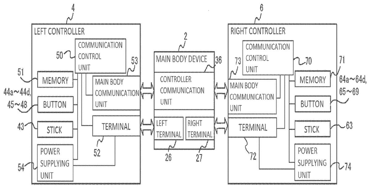
As illustrated inFIG. 4, the left controller4includes a communication control unit50for controlling communication with the main body device2. The communication control unit50is connected to the respective components including the terminal52and a main body communication unit53. According to the present embodiment, the communication control unit50can make both wired communication via the terminal52and wireless communication not via the terminal52but via the main body communication unit53with the main body device2.
The main body communication unit53is connected to the communication control unit50. The main body communication unit53makes wireless communication with the main body device2. Any communication system between the main body device2and the left controller4may be employed, and according to the present embodiment, the main body communication unit53makes communication with the main body device2in the Bluetooth (trademark) standard as described above.
The communication control unit50controls a communication method performed by the left controller4for the main body device2. That is, when the left controller4is mounted on the main body device2, the communication control unit50makes wired communication with the main body device2via the terminal52. When the left controller4is removed from the main body device2, the communication control unit50makes wireless communication with the main body device2(specifically, the controller communication unit36) via the main body communication unit53.
The left controller4includes a memory51such as flash memory. The communication control unit50is configured of a microcomputer (or microprocessor), for example, and performs various kinds of processing by executing firmware stored in the memory51.
The left controller4includes the buttons44ato44d, and45to48. The left controller4further includes the stick43. Each of the buttons44ato44d, and45to48, and the stick43repeatedly outputs the information on an operation performed for it as operation data to the communication control unit50as needed.
FIG. 5is a diagram schematically illustrating a detailed configuration of the stick43. As illustrated inFIG. 5, the stick43includes a tilt detection unit431for detecting a direction and magnitude of tilt of the stick43, and a press detection unit432for detecting the presence of press of the stick43. The tilt detection unit431outputs the operation information on a direction and magnitude of tilt of the stick43as information on an entry by the stick43to the communication control unit50. By way of example, the tilt detection unit431may be variable resistors provided on two axes, and in this case, indicates a resistance value depending on the tilt amount of the stick43in each axial direction, and the direction and magnitude of tilt of the stick43can be known by the two axial components. The press detection unit432outputs the operation information on the presence of press of the stick43as information on an entry by the stick43to the communication control unit50. The press detection unit432is a switch provided below the stick by way of example. The stick63similarly includes a tilt detection unit631for detecting a direction and magnitude of tilt of the stick63, and a press detection unit632for detecting the presence of press of the stick63.
The communication control unit50acquires the information on an entry (specifically, information on operation, or detection result by the detection units) from each input unit (specifically, each of the buttons44ato44dand45to48, and the stick43). The communication control unit50transmits the operation data including the acquired information (or predetermined processed information of the acquired information) to the main body device2. The operation data is repeatedly transmitted per predetermined time. An interval at which the information on an entry is transmitted to the main body device2may be or may not be the same among the input units.
The operation data is transmitted to the main body device2, and thus the main body device2can acquire the entry by the left controller4. That is, the main body device2can determine the operations on the buttons44ato44dand45to48and the stick43on the basis of the operation data.
The left controller4includes a power supplying unit54. According to the present embodiment, the power supplying unit54has a battery and a power control circuit. Though not illustrated, the power control circuit is connected to the battery, and to each unit of the left controller4(specifically, each unit supplied with power from the battery). The power control circuit controls power supply from the battery to each unit. The battery is connected to the terminal52. According to the present embodiment, when the left controller4is mounted on the main body device2, the battery is charged by the power supplied from the main body device2via the terminal52under a predetermined condition.
(Right Controller6)
The right controller6includes a communication control unit70for controlling communication with the main body device2. The right controller6further includes a memory71connected to the communication control unit70. The communication control unit70is connected to the components including the terminal72and a main body communication unit73. The main body communication unit73is connected to the communication control unit70. The main body communication unit73makes wireless communication with the main body device2. Any communication system between the main body device2and the right controller6can be employed, and according to the present embodiment, the main body communication unit73makes communication with the main body device2in the Bluetooth (trademark) standard as described above.
The communication control unit70, the memory71, the terminal72, and the main body communication unit73have the similar functions to the communication control unit50, the memory51, the terminal52, and the main body communication unit53in the left controller4. Thus, the communication control unit70can make communication with the main body device2in both wired communication via the terminal72and wireless communication not via the terminal72but via the main body communication unit73, and controls a communication method performed by the right controller6for the main body device2.
The right controller6includes the similar input units (specifically, the buttons64ato64dand65to69, and the stick63) to the input units in the left controller4. The input units have the similar functions to the input units in the left controller4, and similarly operate. The stick63includes the tilt detection unit631for detecting a direction and magnitude of tilt of the stick63, and a press detection unit632similarly to the stick43(seeFIG. 5). The tilt detection unit631outputs the operation information on a direction and magnitude of tilt of the stick63as information on an entry by the stick63to the communication control unit70. The press detection unit632outputs the operation information on the presence of press of the stick63as information on an entry by the stick63to the communication control unit70.
The right controller6includes a power supplying unit74. The power supplying unit74has the similar function to the power supplying unit54in the left controller4, and similarly operates. That is, the power supplying unit74controls power supply to each unit supplied with power from the battery. When the right controller6is mounted on the main body device2, the battery is charged by the power supplied from the main body device2via the terminal72under a predetermined condition.
[Use Forms]
The left controller4and the right controller6are detachable from the main body device2in the game system1according to the present embodiment as described above. The main body device2can be connected to the stationary monitor via the cradle8. Therefore, the game system1can be used in various use forms described below.
(Mounted State)
FIG. 6is a diagram illustrating an example of how one user grips and uses the game system1in both hands while the left controller4and the right controller6are mounted on the main body device2(which is denoted as mounted state). The mounted state is suitable for one user who plays a game while watching the display22. In the mounted state, the user grips the left controller4with the left hand and grips the right controller6with the right hand. By doing so, the display22of the main body device2is positioned between the right and left hands. Further, the sticks43,63and the operation buttons44ato44d,64ato64dare vertically reverse to each other between the left controller4and the right controller6as described above, and thus one hand (the left thumb in the example ofFIG. 6) easily operates the stick and the other hand (the right thumb in the example ofFIG. 6) easily operates the operation buttons with the right and left hands at the same height.
(Removed State: Single Player)
As described above, the game system1can be used while the left controller4and the right controller6are removed from the main body device2(which is denoted as “removed state”) according to the present embodiment.FIG. 7is a diagram illustrating an example of how one user uses the game system1by gripping the left controller4with the left hand and gripping the right controller6with the right hand in the removed state. As illustrated inFIG. 7, a positional relationship between the left controller4and the right controller6is not fixed in the removed state, and both the controllers can be freely moved.
(Removed State: Two Players)
FIG. 8is a diagram illustrating an example of how each of two users grips one controller thereby to use the game system1in the removed state. In the example ofFIG. 8, one user U1grips the left controller4in both hands and the other user U2grips the right controller6in both hands.
According to the present embodiment, when the positional relationship between the stick63and the operation buttons64ato64din the right controller6is reverse to the positional relationship between the two kinds of operation units in the left controller4when longitudinally-long arranged as illustrated inFIG. 7. Thus, as illustrated inFIG. 8, when two users grip the left controller4and the right controller6in a laterally-long direction, respectively, the positional relationships of the two kinds of operation units are the same between the two controllers. That is, according to the present embodiment, the user can use the left controller4and the right controller6, which are removed from the main body device2, for the two kinds of operation units with the same operation feeling. Thereby, the operability of the controllers can be enhanced.
In the removed state, the four operation buttons44ato44din the left controller4may be used in the same functions as the four operation buttons64ato64din the right controller6(in other words, may be used for making the same instructions). By way of example, the rightward button44amay be used in the same function as the Y button64c, the downward button44bmay be used in the same function as the X button64d, the leftward button44cmay be used in the same function as the A button64a, and the upward button44dmay be used in the same function as the B button64b. In this way, the functions of the operation buttons44ato44dand64ato64dmay be changed between the mounted state and the removed state according to the present embodiment. An instruction for which each operation button is used may be freely determined by a program executed by the main body device2.
(Removed State: Connection to Stationary Monitor)
FIG. 9is a diagram illustrating other example of how one user grips the two controllers thereby to use the game system1in the removed state. As illustrated inFIG. 9, the main body device2is placed on the cradle8and the cradle8is connected to a stationary monitor9so that the user can play a game while watching the screen of the stationary monitor9in the removed state. When an external display device is used in this way, the game system1can be used similarly to a conventional stationary game machine.
The cradle8is connected to the lower terminal30of the main body device2, and receives an image signal from the main body device2via the lower terminal30and outputs it to the stationary monitor9. The cradle8further includes a power supply terminal. The power supply terminal is connected with an AC adapter and the cradle8is supplied with a commercial power supply. The cradle8supplies the power from the commercial power supply to the main body device2via the lower terminal30.
[Game Processing]
Game processing performed by use of the game system1will be described below. The game is played by moving a player character in a3D virtual space and causing the player character to perform various actions. According to the present embodiment, the player character can fly a predetermined support object as an action. By way of example, the player character puts a hat on, and flies the hat. A virtual camera is set in the virtual space and an image shot by the virtual camera in a pseudo manner is displayed on the display22or the stationary monitor9(which will be simply denoted as “display22” below). A position and a direction of the virtual camera may be a position and a direction of a point of view in the virtual space of the image displayed on the display22.
The position and direction of the virtual camera is changed by a user operation as described below, but according to the predetermined embodiment, the position and direction of the virtual camera are determined to show the player character at the center of the screen. The movement and direction change of the player character and the virtual camera in the virtual space are performed by the CPU31in the main body device2according to a predetermined game program on the basis of the operation data on the user entry by the left controller4and the right controller6.
The game according to the present embodiment sets a plurality of play modes including single-player mode and two-player mode. Movement control of the player character and the virtual camera in each mode will be described below.
(Single-Player Mode)
The single-player mode is a mode in which one user plays a game by use of the two controllers. In the play mode, the user can operate the two sticks (the stick43and the stick63) in both hands. It is assumed that the user grips the left controller4with the left hand and grips the right controller6with the right hand thereby to play a game as illustrated inFIG. 7 or 9. The user can move the player character in the virtual space by operating the stick43in the left controller4, and can change the position of the virtual camera relative to the player character by operating the stick63in the right controller6. That is, the stick for operating the player character is separated from the stick for operating the virtual camera in the single-player mode. The user can perform the two operations at the same time. The specific processing will be described below.
The operations of the virtual camera by the stick63in the right controller6will be first described.FIG. 10is a diagram of a positional relationship between a player character P and a virtual camera C in a virtual space as viewed from the side.FIG. 11is a diagram of the state ofFIG. 10as viewed from above. The virtual camera C is set to capture the player character P substantially at the center of an angle of view (eyesight range) A at any position as illustrated inFIGS. 10 and 11.
The virtual camera C moves on a horizontal trajectory HT in response to a horizontal operation of the stick63, and moves on a vertical trajectory VT in response to a vertical operation of the stick63. The horizontal trajectory HT and the vertical trajectory VT are set with reference to the player character P. According to the present embodiment, the horizontal trajectory HT is the circumference of a horizontal circle with the radius R about the player character P, and the vertical trajectory VT is the circumference of a vertical circle with the radius R about the player character P. That is, a distance between the player character P and the virtual camera C is kept at R and the virtual camera C moves on the spherical surface with the radius R about the player character P according to the present embodiment.
FIG. 12is a diagram illustrating how the virtual camera C is moved by operating the stick63. The virtual camera C is at position cpt0at time t0. At this time, the virtual camera C captures the player character P substantially at the center of the angle of view, and the distance between the virtual camera C and the player character P is R. When the stick63is tilted rightward in this state, the virtual camera C moves leftward along the trajectory HT in the virtual space by a movement component M1, and moves to position cpt1at time t1. That is, the virtual camera C moves around the player character P. The magnitude of the movement component M1(the amount of move-around) depends on the tilt amount of the stick63, and as the tilt amount is larger, the movement component M1is also larger.
The virtual camera C automatically changes its direction to capture the player character P substantially at the center of an angle of view At1even at position cpt1. Time t1is one processing frame after time t0. The processing frame is a minimum unit time in which the CPU31receives the operation data from the left controller4and the right controller6to perform the processing for moving the player character P and the virtual camera C, such as 1/15 seconds.
The direction in which the stick63is tilted (rightward) is reverse to the direction in which the virtual camera C moves (leftward) according to the present embodiment, but the virtual camera C moves around to the left side of the player character P by the movement component M1so that the screen displayed on the display22is moved to show the right side of the player character P and the direction in which the stick63is tilted (rightward) matches with the direction in which the angle of view of the virtual camera C is changed (rightward). Thus, the user tilts the stick63in his/her desired direction, and can change the angle of view irrespective of movement of the virtual camera C.
Though not illustrated, the user vertically operates the stick63thereby to vertically move the virtual camera C along the trajectory VT in the virtual space similarly as described above. Also in this case, the virtual camera C automatically changes the direction along with its movement to capture the player character P substantially at the center of the angle of view. When the stick63is tilted downward, the virtual camera C moves upward on the trajectory VT, and when the stick63is tilted upward, the virtual camera C moves downward on the trajectory VT.
The virtual camera C can horizontally and vertically move at the same time when the stick63is obliquely tilted, and in this case, the tilt of the stick63is decomposed laterally and longitudinally, and a lateral movement component (the amount of move-around) and a vertical movement component (the amount of move-around) of the virtual camera C are calculated according to the respective tilt amounts, and the virtual camera C is moved according to the combined movement components.
When the stick63continues to be tilted, the calculation is made per processing frame to calculate a position of the virtual camera C and to change the screen. In the example ofFIG. 12, the stick63continues to be tilted so that the virtual camera C moves around the spherical surface with the radius R about the player character P.
Movement of the player character P and movement of the virtual camera C by the stick43in the left controller4will be described below. The player character P moves in the virtual space in a direction in which the stick43is tilted. At this time, the virtual camera C moves in the virtual space to follow the player character P. Also in this case, the direction of the virtual camera C is set such that the player character P is positioned substantially at the center of the angle of view A at any position.
FIG. 13is a diagram of the virtual space viewed from above, which explains how the virtual camera C follows the player character P when the player character P is laterally moved.FIG. 13illustrates how the stick43is tilted rightward to move the player character P rightward. The player character P is at position ppt0at time t0. At this time, the virtual camera C is oriented to capture the player character P substantially at the center of the angle of view, and the distance between the virtual camera C and the player character P is R. When the stick43is tilted rightward in this state, the player character P moves rightward in the virtual space by a movement component M2, and moves to position ppt1at time t1. The trajectory HT is also changed from a trajectory HTt0with reference to the player character P at position ppt0to a trajectory HTt1with reference to the player character P at position ppt1along with the movement. The magnitude (length) of the movement component M2depends on the tilt amount of the stick43, and as the tilt amount is larger, the movement component M2is also larger.
The virtual camera C moves from position cpt0to position cpt1by a movement component M3along with the movement of the player character P. Position cpt1of the moved virtual camera C is found as an intersection point between the line L connecting position ppt1of the moved player character P and position cpt0of the virtual camera C before movement and the trajectory HTt1with reference to the moved player character P. In other words, the movement component M3is such that the virtual camera C moves toward the moved player character P until the distance between the virtual camera C and the player character P reaches R. Also in this case, the virtual camera C is set in a direction in which the player character P is positioned substantially at the center of the angle of view at position cpt1as movement destination. The stick43continues to be tilted so that the movement of the player character P and the movement of the virtual camera C are performed per processing frame.
The stick43is obliquely tilted so that the player character P can move in the lateral direction and in the depth direction, and in this case, the tilt of the stick43is decomposed laterally and longitudinally, and the movement components in the lateral direction and in the depth direction of the player character P are calculated depending on the respective tilt amounts, and the player character P is moved depending on the combined movement components. The position of the virtual camera C following the player character P moving in this way is similarly found as an intersection point between the line connecting the position of the virtual camera C before movement and the position of the moved player character P and the horizontal trajectory HT with reference to the moved player character P.
FIG. 14is a diagram illustrating how the stick43and the stick63are operated at the same time thereby to move the player character P and the virtual camera C together. When the stick43and the stick63are tilted at the same time, the player character P moves in the virtual space according to the tilt of the stick43and the virtual camera C moves by a movement component M13in which the movement component M1of move-around due to the tilt of the stick63described with reference toFIG. 12is combined with the movement component M3of follow described with reference toFIG. 13.
In the example ofFIG. 14, the stick43is tilted to the upper right to move the player character P to the upper right from position ppt0to position ppt1, and the stick63is tilted leftward to move the virtual camera C around to the right side of the player character P. According to the present embodiment, the movement component M1of move-around is added along the trajectory HTt1with reference to position ppt1of the moved player character P from position cpt′ moved by the movement component M3of follow, thereby calculating the final movement component M13. Additionally, the movement component M1of move-around is calculated along the trajectory HTt0with reference to the player character P at position ppt0according to the tilt of the stick63, and then an intersection point between the line connecting the movement by the movement component M1and position ppt1of the moved player character P and the trajectory HTt1with reference to the moved player character P is assumed as a final movement destination of the virtual camera C at position cpt0, and thus the movement of follow and the movement of move-around may be combined.
As described above, in the single-player mode, the direction in which the player character P moves by use of the stick43is independent of the direction in which the virtual camera C moves around the player character P by use of the stick63, which are performed at the same time, and each direction can be arbitrarily input. The stick63is obliquely tilted, thereby moving the virtual camera C around in the lateral direction and in the vertical direction.
As illustrated inFIG. 13, the control method for moving the virtual camera C to follow the moving player character P is denoted as “first control method” and the algorithm for finding a movement component of follow of the virtual camera C in response to an operation of the stick is denoted as “first algorithm”. In the single-player mode according to the present embodiment, the CPU31finds a movement component of follow of the virtual camera C in the first algorithm in response to tilt of the stick43, and performs the first control method for moving the virtual camera C according to the movement component of follow.
As illustrated inFIG. 12, the algorithm for finding a movement component of move-around of the virtual camera in response to an operation of the stick is denoted as “second algorithm” and, as illustrated inFIG. 14, the control method for moving the virtual camera C by a movement component in which the movement component of follow of the virtual camera C found in the first algorithm is combined with the movement component of move-around of the virtual camera C found in the second algorithm is denoted as “second control method.” In the single-player mode according to the present embodiment, the CPU31finds a movement component of follow of the virtual camera C in the first algorithm in response to tilt of the stick43, and finds a movement component of move-around of the virtual camera C in the second algorithm depending on tilt of the stick63thereby to perform the second control method for moving the virtual camera C by the movement components including the movement components of follow and move-around.
(Two-Player Mode)
Each of two users uses one stick in the two-player mode. A user can operate the player character P to fly a support object as described above in the game according to the present embodiment. According to the present embodiment, the player character P can be moved and the virtual camera C can be operated by the left controller4, and the action of flying a support object can be performed by the right controller6. By way of example, the support object is a hat which the player character P puts on, and the hat may be flown by the right controller6around the player character P operated by the left controller4. That is, the movement of the player character P and the movement of the virtual camera C (move-around) are operated by the two sticks43and63, respectively in the single-player mode, while the movements are realized by one stick in the two-player mode.
FIG. 15is a diagram illustrating how the virtual camera C moves (moves around) in the two-player mode. In the two-player mode, the stick43is tilted while the second L button47in the left controller4is being pressed, thereby moving the virtual camera C in the virtual space. That is, while the second L button47is being pressed, the CPU31does not move the player character P even when the stick43is tilted, and moves the virtual camera C around the player character P according to the tilt direction and the tilt amount of the stick43.
Thereby, as illustrated inFIG. 15, the virtual camera C can be moved around the player character P similarly as in the example ofFIG. 12. When receiving the operation data indicating press of the second L button47and the operation data indicating tilt of the stick43in the two-player mode, the CPU31calculates the movement component M1in the second algorithm, and moves the virtual camera C by the calculated movement component M1. That is, the two-player mode is the same as the single-player mode in that the movement component of move-around of the virtual camera C is found in the second algorithm thereby to control the movement of the virtual camera C.
Consequently, the virtual camera C at position cpt0at time t0moves to position cpt1at time t1along the trajectory HT with the radius R about the player character P by the movement component M1. As in the single-player mode, the CPU31determines the direction of the virtual camera C at destination position cpt1such that the player character P is captured substantially at the center of the angle of view At1.
FIG. 16is a diagram illustrating how the player character P moves in the two-player mode. In the two-player mode, the stick43is tilted without pressing the second L button47in the left controller4, thereby moving the player character P in the virtual space. Thereby, as illustrated inFIG. 16, the player character P can be moved similarly as in the example ofFIG. 13, and the virtual camera C moves to follow the player character P along with its movement.
When receiving the operation data indicating tilt of the stick43without receiving the operation data indicating press of the second L button47in the two-player mode, the CPU31calculates the movement component M3in the first algorithm, and performs the first control method for moving the virtual camera C by the calculated movement component M3. That is, the two-player mode is the same as the single-player mode in that the movement of the virtual camera C is controlled in the first algorithm and the first control method.
Consequently, the player character P at position ppt0at time t0moves to position ppt1at time t1by the movement component M2depending on the tilt direction and the tilt amount of the stick43. The virtual camera C moves to position cpt1at time t1as an intersection point between the line connecting original position cpt0and position ppt1of the moved player character P and the trajectory HTt1with reference to position ppt1of the moved player character P by the movement component M3. As in the single-player mode, the CPU31determines the direction of the virtual camera C at destination position cpt1such that the player character P is captured substantially at the center of the angle of view At1.
FIG. 17is a diagram illustrating how the player character P and the virtual camera C are moved at the same time in the two-player mode. As described above, movement of the player character P and movement of the virtual camera C is witched depending on whether the second L button47is being pressed when the stick43is operated in the two-player mode. Thus, the virtual camera C cannot be moved (moved around) only by the function while the player character P is being moved. Thus, simultaneous movement of the player character P and the virtual camera C is realized as follows by use of the press detection unit432of the stick43according to the present embodiment.
When receiving the operation data that the stick43is pressed from the press detection unit432and receiving the operation data that the stick43is tilted from the tilt detection unit431at the same time, the CPU31moves the player character P according to the tilt direction and the tilt amount, and moves the virtual camera C (around) according to the tilt direction and the tilt amount.
Specifically, the CPU31first moves the player character P in the virtual space according to the tilt direction and the tilt amount, calculates the movement component M3to an intersection point cpt′ between the line L connecting position ppt1of the moved player character P and position cp50of the virtual camera C before movement and the trajectory HTt1with reference to the moved player character P (or calculates the movement component M2in the first algorithm), calculates the movement component M1to move around along the trajectory HTt1with reference to the moved player character P according to the tilt direction and the tilt amount (or calculates the movement component M1in the second algorithm), and moves the virtual camera C to position cpt1from position cpt′ by the movement component M1. That is, the CPU31moves the virtual camera C from original position cpt0to position cpt1by the movement component M13in which the movement component M3for following the player character P is combined with the movement component M1of move-around of the virtual camera C.
That is, the two-player mode is the same as the single-player mode in that when the player character P and the virtual camera C are instructed to move at the same time, the movement component M3of follow is calculated in the first algorithm, the movement component M1of move-around is calculated in the second algorithm, and the virtual camera C is moved in the second control method for moving by the combined movement components. In the two-player mode, when the player character P and the virtual camera C are moved at the same time, the tilt direction and the tilt amount of the stick43for moving them are the same between movement of the player character P and movement of the virtual camera C.
In the two-player mode according to the present embodiment, when the stick43is pressed and tilted at the same time, the vertical component of tilt is not reflected on the movement component M1of the virtual camera C. By doing so, when the stick43is tilted while being pressed, the virtual camera C can be prevented from vertically moving around when the player character P is to be moved in the depth direction in the virtual space.
Movement of the player character P when the stick43is continuously tilted in the two-player mode will be described below with reference toFIGS. 18 and 19.FIG. 18is a diagram illustrating how the player character P moves and the virtual camera C accordingly follows it while the operation of moving the player character P is continued, andFIG. 19is a diagram illustrating how the player character P and the virtual camera C move when the virtual camera C is moved along with movement of the player character P. When the operation of moving the player character P is continued, the control method for moving the player character P while the virtual camera C is following it as illustrated inFIG. 18is denoted as “third control method,” and the control method for moving the player character P while the virtual camera C is following and moving around it as illustrated inFIG. 19is denoted as “fourth control method.”
In any of the third and fourth control methods, when the stick43is tilted rightward, for example, the CPU31moves the player character P to the right side of an image shot by the virtual camera C in a pseudo manner in each processing frame. When the player character P is instructed to move rightward, it moves rightward to be orthogonal to the line connecting the virtual camera C and the player character P. The virtual camera C moves along with the movement of the player character P in any of the third and fourth control methods, and thus when the stick43continues to be tilted rightward, the player character P does not linearly move in the virtual space and moves in an arc from position ppt0, to position ppt1, position ppt2, position ppt3, . . . , as illustrated inFIGS. 18 and 19. A movement distance of the player character P is drawn to be relatively large in one processing frame inFIGS. 18 and 19, but the processing frame is made sufficiently small in actual processing, and thus the player character P moves in a smooth arc.
When the third control method inFIG. 18is compared with the fourth control method inFIG. 19, while the virtual camera C simply follows the player character P in the example ofFIG. 18, the virtual camera C moves around the player character P in the example ofFIG. 19, and thus a larger angle is formed fora previous processing frame and a movement component of the player character P is calculated for a next processing frame. Consequently, when the stick43is tilted while pressed as inFIG. 19, the player character P moves in an arc with a smaller R in the virtual space than when the stick43is tilted without being pressed as inFIG. 18.
As described above, the game system1according to the present embodiment includes the stick43for being tilted in a direction in which the player character P moves in the virtual space and for being pressed for an operation of the virtual camera C in order to display the virtual space, the tilt detection unit431for detecting tilt of the stick43by the user as tilt corresponding to a tilt direction, the press detection unit432for detecting press of the stick43by the user as press, and the CPU31for moving the player character P on the basis of the tilt, when the stick is not pressed but tilted, moving the virtual camera C on the basis of the tilt in the first control method, and when the stick is pressed and tilted at the same time, moving the virtual camera C on the basis of the tilt in the second control method different from the first control method.
The CPU31moves the virtual camera C to follow the player character P moving in a direction corresponding to tilt in the first control method, and follows the player character P moving in a direction corresponding to tilt and moves the virtual camera C around the player character P in a direction corresponding to tilt in the second control method. Further, the CPU31moves the virtual camera C around the player character P in association with only the lateral component of tilt in the second control method.
The CPU31moves the player character P in an arc with a relatively small R on the basis of the lateral component of tilt when the stick is tilted and pressed at the same time, and moves the player character P in an arc with a relatively large R on the basis of the lateral component of tilt when the stick is not pressed but tilted.
The left controller4includes the stick43, the tilt detection unit431, and the press detection unit432, the game system1further includes the right controller6provided with the stick63for being tilted in a direction in which the virtual camera C moves in the virtual space, and the CPU31can select the single-player mode in which one player operates the left controller4and the right controller6and the two-player mode in which one player operates the left controller4and the other player operates the right controller, where the virtual camera C is moved on the basis of tilt by the stick63irrespective of press in the single-player mode and the virtual camera C is moved on the basis of tilt by the stick43in the first control method or the second control method in the two-player mode.
The CPU31employs a different correspondence between a direction of tilt by the stick43and a direction in which the player character P moves in the virtual space between the single-player mode and the two-player mode. Specifically, the correspondence is set such that up, down, left and right of the screen match with up, down, left and right of the stick when the controller is longitudinally gripped in the single-player mode, and the correspondence is set such that up, down, left, and right of the screen match with up, down, left, and right of the stick when the controller is laterally gripped in the two-player mode.
The game system1according to the present embodiment includes the stick43for being tilted and pressed, and the CPU31for moving the player character on the basis of tilt, when the stick43is not pressed but tilted, calculating a movement component of the virtual camera C on the basis of tilt in the first algorithm and moving the virtual camera C including the calculated movement component, and when the stick43is tilted and pressed at the same time, calculating a movement component of the virtual camera C on the basis of tilt in the first algorithm, calculating a movement component of the virtual camera C on the basis of tilt in the second algorithm and moving the virtual camera C including the calculated movement component.
The game system1according to the present embodiment includes the left controller4provided with the stick43for being tilted and pressed, the right controller6provided with the stick63for being tilted, and the main body device2capable of selecting the single-player mode in which one player operates the left controller and the second controller or the two-player mode in which one player operates the left controller and the other player operates the right controller and directed for moving the virtual camera in a selected mode, and the main body device2calculates a movement component of the virtual camera C on the basis of tilt of the stick43in the first algorithm, calculates a movement component of the virtual camera C on the basis of tilt of the stick63in the second algorithm, and moves the virtual camera C by the calculated movement component in the single-player mode, calculates a movement component of the virtual camera C on the basis of tilt of the stick43in the first algorithm, and calculates a movement component of the virtual camera C on the basis of tilt of the stick43in the second algorithm and moves the virtual camera C including all the calculated movement components when the stick43is tilted and pressed at the same time in the two-player mode.
The player character is to be moved according to the above embodiment, but the present technique is not limited thereto and the control of moving other character may be performed in the above method.
The presence of move-around of the virtual camera C is switched depending on whether the stick43is pressed in the two-player mode according to the present embodiment, but the present technique is not limited thereto. For example, a button is provided on top of the stick43, and the presence of move-around of the virtual camera C may be switched depending on whether the button is pressed. The presence of move-around of the virtual camera C may be switched depending on whether the second R button48is pressed. According to the present embodiment, the presence of move-around of the virtual camera C can be switched by the operation of only the stick43without operating the two operation members including the button and the stick.
The present embodiment has been described assuming that the stick is used as direction input means, but the direction input means is not limited thereto, and an arrow key or slide pad may be employed. Also in the case, the arrow key or slide pad may be provided with a press detection unit for detecting press, thereby inputting a direction while pressing the stick.
According to the present embodiment, the tilt detection unit431detects not only a tilt direction but also the tilt amount thereby to change the movement amount (the magnitude of a movement component) of the player character P or the virtual camera C depending on the magnitude of tilt, but the tilt detection unit431may detect only a tilt direction and may not detect the tilt amount, and the CPU31may find only the directions of the player character P and the virtual camera C assuming a movement component of the player character P and a movement component of move-around of the virtual camera C at certain constant values in one processing frame. Also when the tilt detection unit431detects the tilt amount, the CPU31may calculate the magnitude of a movement component with the tilt amount as discrete value such as two-stage value.
Claims
- A game system comprising: a first direction input circuitry configured to accept a first direction relating to a moving direction of a character in a virtual space;an operation input circuitry configured to accept an operation relating to an operation of a virtual camera in the virtual space;and at least one hardware processor configured to: move the character in the virtual space based on the input first direction, when the operation is not input but the first direction is input, move the virtual camera according to a first control method, and when the first direction and the operation are input at the same time, move the virtual camera according to a second control method based on the input first direction.
- The game system according to claim 1 , wherein the at least one processor is further configured to: move the virtual camera to follow movement of the character in the first control method, and move the virtual camera to follow movement of the character in a direction corresponding to the input first direction in the second control method.
- The game system according to claim 1 , wherein at least one processor is further configured to: move the virtual camera toward the character in a direction corresponding to a predetermined direction component of the input first direction in the second control method.
- The game system according to claim 1 , further comprising: a stick capable of being tilted and pressed by a user operation, wherein the first direction input circuitry is configured to detect tilt of the stick as the input first direction corresponding to the tilt direction, and the operation input circuitry is configured to detect press of the stick by the user as the input operation.
- The game system according to claim 1 , further comprising: a first controller provided with the first direction input circuitry and the operation input circuitry;and a second controller provided with a second direction input circuitry configured to accept a second direction for a direction in the virtual camera moves in the virtual space, wherein the at least one hardware processor is further configured to: perform mode selection processing of selecting among a single-player mode and a two-player mode, the single-player mode in which one player operates the first controller and the second controller, the two-player mode in which one player operates the first controller and another player operates the second controller, move the virtual camera on the basis of the input second direction in the single-player mode, move the virtual camera according to the first control method when the operation is not input but the first direction is input, and move the virtual camera according to the second control method based on the input first direction when the first direction and the operation are input at the same time in the two-player mode.
- The game system according to claim 5 , wherein the at least one hardware processor is configured to employ a different correspondence between the input first direction and the moving direction of the character in the virtual space between the single-player mode and the two-player mode.
- A game system configured to move a character in a virtual space and generate an image based on a virtual camera set in the virtual space, the game system comprising: a stick capable of being tilted and pressed;and a processing system including at least one hardware processor, the processing system configured to move the character in the virtual space depending on tilt when the stick is tilted but not pressed, and move the character in the virtual space depending on the tilt and move the virtual camera relative to the character depending on the tilt when the stick is tilted and pressed.
- A non-transitory storage medium storing a game program for use with a computer of a game system that comprises a stick capable of being tilted and pressed, a tilt detection circuitry configured to detect the tilt, and a press detection circuitry configured to detect the press, the game program comprising instructions configured to cause the computer to: move a character in a virtual space depending on tilt when the tilt detection circuitry detects the tilt and the press detection circuitry does not detect the press, and move the character in the virtual space depending on the tilt and to move the virtual camera relative to the character depending on the tilt when the tilt detection circuitry detects the tilt and the press detection circuitry detects the press.
- The non-transitory storage medium according to claim 8 , wherein the game program comprises further instructions that are configured to cause the computer to: move the virtual camera to follow movement of the character when the tilt detection circuitry detects the tilt and the press detection circuitry does not detect the press, and move the virtual camera to follow movement of the character in a direction corresponding to the tilt when the tilt detection circuitry detects the tilt and the press detection circuitry detects the press.
- The non-transitory storage medium according to claim 8 , wherein the game program comprises further instructions that are configured to cause the computer to move the virtual camera toward the character in a direction corresponding to a predetermined direction component of the tilt when the tilt detection circuitry detects the tilt and the press detection circuitry detects the press.
- The non-transitory storage medium according to claim 8 , wherein the game system comprises a first controller provided with the stick, the tilt detection circuitry and the press detection circuitry, and a second controller provided with a second stick and second tilt detection circuitry, wherein the game program comprises further instructions that are configured to cause the computer to: perform mode selection processing of selecting either a single-player mode in which one player operates the first controller and the second controller or a two-player mode in which one player operates the first controller and another player operates the second controller, move the virtual camera on the basis of tilt of the second stick in the second controller in the single-player mode, move a character in a virtual space depending on the tilt when the press detection circuitry in the first controller does not detect the press but the tilt detection circuitry in the first controller detects the tilt in the two-player mode, move the character in the virtual space depending on the tilt detected by the tilt detection circuitry in the first controller and to move the virtual camera relative to the character depending on the tilt detected by the tilt detection circuitry in the first controller when the press detection circuitry in the first controller detects the press and the tilt detection circuitry in the first controller detects the tilt at the same time.
- The non-transitory storage medium according to claim 11 , wherein the game program comprises further instructions that are configured to cause the computer to employ a different correspondence between the input first direction and a direction in which the character moves in the virtual space between the single-player mode and the two-player mode.
- A game processing device comprising: a processing system that includes at least one hardware processor, the processing system configured to: receive, via a first direction input device, data for entry of a first direction relating to a moving direction of a character in a virtual space;receive, via an operation input device, data for entry of an operation relating to an operation of a virtual camera in the virtual space;and move the virtual camera according to a first control method based on determination that the entry of the operation is not received concurrently with reception of the entry of the first direction, and move the virtual camera according to a second control method based on the input first direction based on determination that the entry of the first direction and the entry of the operation are received at the same time.
- The game processing device of claim 13 , wherein: the first direction input device includes a tilt sensor, and the operation input device includes a push sensor.
Disclaimer: Data collected from the USPTO and may be malformed, incomplete, and/or otherwise inaccurate.