U.S. Pat. No. 10,143,917
OPERATION SYSTEM, GAME SYSTEM, AND GAME CONTROLLER CAPABLE OF IDENTIFYING CONNECTED DEVICE WITH SIMPLIFIED SCHEME
AssigneeNINTENDO CO., LTD.
Issue DateApril 19, 2017
Illustrative Figure
Abstract
An example connected device includes a first battery for supplying electric power to a game controller, a first terminal electrically connected to the game controller, and a resistor connected to the first terminal. The game controller includes a controlled component, a second battery for supplying electric power to the controlled component, a second terminal electrically connected to the connected device, a voltage detecting circuit detecting a voltage value in accordance with a current which flows through the resistor when the first terminal and the second terminal are connected to each other, and a control circuit. The control circuit discriminates a device connected to the game controller based on the detected voltage value, and switches from the second battery to the first battery when the discriminated device is the connected device while electric power is supplied from the second battery to the controlled component.
Description
DETAILED DESCRIPTION OF NON-LIMITING EXAMPLE EMBODIMENTS This embodiment will be described in detail with reference to the drawings. The same or corresponding elements in the drawings have the same reference characters allotted and description thereof will not be repeated. [A. Information Processing System] An apparatus configuration relating to an information processing system based on the present embodiment will be described. The information processing system based on the present embodiment is configured at least with an information processing apparatus described below. For example, an information processing apparatus may be a portable (also referred to as mobile) device such as a portable game device, a portable telephone, or a smartphone, a stationary apparatus such as a personal computer or a home game console, or a large apparatus such as an arcade game machine. In the present example, a game device representing one example of an information processing apparatus will be described by way of example. Though a game controller provided for a game device will be described in the present example by way of example of an operation apparatus, limitation in particular to a game controller is not intended and any operation apparatus may be applicable so long as it functions as an input device capable of transmitting operation data to an information processing apparatus. (a1: Overall Configuration of Game Device) FIG. 1is an example non-limiting schematic diagram showing appearance of a game device1based on the present embodiment. As shown inFIG. 1, game device1includes a main body apparatus2, a left controller3, and a right controller4. Main body apparatus2includes a display12representing one example of a display portion and performs various types of processing including game processing in game device1. FIG. 2is an example non-limiting schematic diagram showing appearance of another manner of game device1based on the present embodiment. As shown inFIG. 2, left ...
DETAILED DESCRIPTION OF NON-LIMITING EXAMPLE EMBODIMENTS
This embodiment will be described in detail with reference to the drawings. The same or corresponding elements in the drawings have the same reference characters allotted and description thereof will not be repeated.
[A. Information Processing System]
An apparatus configuration relating to an information processing system based on the present embodiment will be described. The information processing system based on the present embodiment is configured at least with an information processing apparatus described below.
For example, an information processing apparatus may be a portable (also referred to as mobile) device such as a portable game device, a portable telephone, or a smartphone, a stationary apparatus such as a personal computer or a home game console, or a large apparatus such as an arcade game machine. In the present example, a game device representing one example of an information processing apparatus will be described by way of example. Though a game controller provided for a game device will be described in the present example by way of example of an operation apparatus, limitation in particular to a game controller is not intended and any operation apparatus may be applicable so long as it functions as an input device capable of transmitting operation data to an information processing apparatus.
(a1: Overall Configuration of Game Device)
FIG. 1is an example non-limiting schematic diagram showing appearance of a game device1based on the present embodiment.
As shown inFIG. 1, game device1includes a main body apparatus2, a left controller3, and a right controller4. Main body apparatus2includes a display12representing one example of a display portion and performs various types of processing including game processing in game device1.
FIG. 2is an example non-limiting schematic diagram showing appearance of another manner of game device1based on the present embodiment.
As shown inFIG. 2, left controller3and right controller4may be constructed as being detachable from main body apparatus2. Left controller3and right controller4may integrally be constructed or left controller3and right controller4may be constructed as separate apparatuses. Thus, left controller3and right controller4corresponding to an operation portion may be constructed separately from main body apparatus2.
Left controller3can be attached to a left side (a side of a positive direction of an x axis shown inFIG. 1) of main body apparatus2. Right controller4can be attached to a right side (a side of a negative direction of the x axis shown inFIG. 1) of main body apparatus2. In the description below, left controller3and right controller4may collectively be referred to as a “controller”. A more specific configuration example of main body apparatus2, left controller3, and right controller4will be described below.
(a2: Structure of Main Body Apparatus)
FIG. 3is an example non-limiting diagram of main body apparatus2based on the present embodiment when viewed from six sides.
Referring toFIG. 3, main body apparatus2has a housing11substantially in a form of a plate.
A main surface of housing11(that is, a front surface or a surface where display12is provided) is substantially in a rectangular shape. In the description below, housing11is in a horizontally long shape and a longitudinal direction of the main surface (that is, the direction of the x axis shown inFIG. 1) is referred to as a lateral direction (or a left-right direction) and a direction of a short side of the main surface (that is, a direction of a y axis shown inFIG. 1) is referred to as a vertical direction (or an up-down direction). A direction perpendicular to the main surface of housing11(that is, a direction of a z axis shown inFIG. 1) is referred to as a direction of depth (or a front-rear direction).
Main body apparatus2can be used with its main surface being laterally oriented or with its surface being vertically oriented when a user holds the main body apparatus. Therefore, denotation as the lateral direction and the vertical direction is given for the sake of convenience of description.
A shape and a size of housing11can arbitrarily be designed. For example, in another embodiment, a protrusion portion or a grip portion for facilitating holding by a user may be added to housing11.
(1) Member Provided on Main Surface of Housing11
As shown inFIGS. 1 to 3, display12is provided on the main surface of housing11of main body apparatus2. Display12shows an image obtained or generated by main body apparatus2(which may be a still image or moving images). When game processing is performed, display12shows a virtual space and an object in the virtual space. Though display12is typically implemented by a liquid crystal display (LCD), a display apparatus of any type can be adopted.
A touch panel13is provided on a screen of display12. Typically, a device of a type accepting a multi-touch input (for example, a capacitance type) is adopted as touch panel13. For example, a device of any type such as a device of a type accepting a single-touch input (for example, a resistive film type) can be adopted as touch panel13.
Speaker holes11aand11bare provided in the main surface of housing11of main body apparatus2and sound generated from a speaker (a speaker88shown inFIG. 7) arranged in housing11is output through speaker holes11aand11b.
Two speakers are provided in main body apparatus2and speaker holes11aand11bare provided in correspondence with respective positions of a left speaker and a right speaker. Speaker hole11ais provided on a left side of display12in correspondence with the left speaker and speaker hole11bis provided on a right side of display12in correspondence with the right speaker.
A position, a shape, and the number of speaker holes11aand11bcan arbitrarily be designed. For example, in another embodiment, speaker holes11aand11bmay be provided in a side surface or a rear surface of housing11.
(2) Member Provided on Left Side Surface of Housing11
A left rail member15for removably attaching left controller3to main body apparatus2is provided in a left side surface of housing11. Left rail member15extends along the up-down direction in the left side surface of housing11. Left rail member15is in a shape allowing engagement thereof with a slider (a slider40shown inFIG. 4) for left controller3. A slide mechanism is formed by left rail member15and slider40. With such a slide mechanism, left controller3can slidably and removably be attached to main body apparatus2.
A left terminal17is provided in the left side surface of housing11. Left terminal17is a terminal for wired communication between main body apparatus2and left controller3. Left terminal17is provided at a position where it comes in contact with a terminal (a terminal42shown inFIG. 4) of left controller3when left controller3is attached to main body apparatus2. Left terminal17should be arranged at a position where the left terminal of main body apparatus2and the terminal of left controller3are in contact with each other while left controller3is attached to main body apparatus2. By way of example, as shown inFIG. 3, left terminal17is provided around a lower end portion of left rail member15.
(3) Member Provided in Right Side Surface of Housing11
As shown inFIG. 3, a feature similar to the feature provided in the left side surface is provided in a right side surface of housing11. A right rail member19for removably attaching right controller4to main body apparatus2is provided in the right side surface of housing11. Right rail member19extends along the up-down direction in the right side surface of housing11. Right rail member19is in a shape allowing engagement thereof with a slider (a slider62shown inFIG. 5) for right controller4. A slide mechanism is formed by right rail member19and slider62. With such a slide mechanism, right controller4can slidably and removably be attached to main body apparatus2.
Right rail member19is in a shape similar to left rail member15. Right rail member19is in a grooved shape similar in cross-sectional shape to left rail member15. Right rail member19does not have to be exactly the same in shape as left rail member15. For example, another embodiment may be constructed such that slider62for right controller4cannot be engaged with left rail member15and/or slider40for left controller3cannot be engaged with right rail member19by making a size and/or a shape of the groove different between left rail member15and right rail member19.
A right terminal21is provided in the right side surface of housing11. Right terminal21is a terminal for wired communication between main body apparatus2and right controller4. Right terminal21is provided at a position where it comes in contact with a terminal (a terminal64shown inFIG. 5) of right controller4when right controller4is attached to main body apparatus2. Right terminal21should be arranged at any position where the right terminal of main body apparatus2and the terminal of right controller4are in contact with each other while right controller4is attached to main body apparatus2. By way of example, as shown inFIG. 3, right terminal21is provided around a lower end portion of right rail member19.
(4) Member Provided on Upper Side Surface of Housing11
As shown inFIG. 3, a first slot23for attaching a storage medium of a first type is provided in an upper side surface of housing11. A lid portion which can be opened and closed is provided in an opening in first slot23as a typical feature, and a storage medium of the first type can be inserted in first slot23while the lid portion is open. The storage medium of the first type is, for example, a storage medium exclusively designed for game device1and a game device of the same type (for example, a dedicated memory card). The storage medium of the first type is used, for example, for storing data used in main body apparatus2(for example, data saved for an application) and/or a program executed in main body apparatus2(for example, a program for an application).
A power button28for switching on and off main body apparatus2is provided on the upper side surface of housing11.
When power button28is pressed and held (for example, power button28is continuously pressed for a prescribed time period or longer), processing for switching on and off main body apparatus2is performed.
An audio input and output terminal25(specifically an earphone jack) is provided in the upper side surface of housing11. A microphone or an earphone can be attached to audio input and output terminal25.
(5) Member Provided on Lower Side Surface of Housing11
As shown inFIG. 3, a lower terminal27for wired communication between main body apparatus2and a cradle5which will be described later is provided in a lower side surface of housing11. Lower terminal27is provided at a position where it comes in contact with a terminal of cradle5when main body apparatus2is attached to cradle5. Typically, a universal serial bus (USB) connector (more specifically, a female connector) can be adopted as lower terminal27.
A second slot24for attaching a storage medium of a second type different from the first type is provided in the lower side surface of housing11. Second slot24may be provided in the surface where first slot23is provided. A lid portion which can be opened and closed is provided in an opening in second slot24as a typical feature, and a storage medium of the second type can be inserted in second slot24while the lid portion is open. The storage medium of the second type may be, for example, a general-purpose storage medium (for example, an SD card). The storage medium of the second type is used, for example, for storing data used in main body apparatus2(for example, data saved for an application) and/or a program executed in main body apparatus2(for example, a program for an application), similarly to the storage medium of the first type.
A position, a shape, and the number of components (specifically, a button, a slot, and a terminal) provided in housing11described above can arbitrarily be designed. For example, in another embodiment, some of power button28, first slot23, and second slot24may be provided in another side surface or the rear surface of housing11. Some of the components do not have to be provided.
(a3: Structure of Left Controller)
FIG. 4is an example non-limiting diagram of left controller3based on the present embodiment when viewed from six sides.
Referring toFIG. 4, left controller3has a housing31substantially in a form of a plate. A main surface of housing31(that is, a front surface or a surface on a side of a negative direction of the z axis shown inFIG. 1) is substantially in a rectangular shape. Housing31is in a vertically long shape, that is, long in the up-down direction (that is, the direction of the y axis shown inFIG. 1).
Left controller3can be used with its main surface being vertically oriented or with its surface being horizontally oriented when a user holds the left controller while the left controller is detached from main body apparatus2.
An analog stick32is provided in left controller3. As shown inFIG. 4, analog stick32is provided on the main surface of housing31. Analog stick32represents one example of a direction instruction portion with which a direction can be input. Analog stick32includes a stick member which can be tilted in all directions (that is, a 360° direction including up, down, left, right, and diagonal directions) in parallel to the main surface of housing31. The analog stick is an analog input device with which a user can input a direction in accordance with a direction of tilt by titling the stick member. Analog stick32may further be constructed to be able to give an input of magnitude in accordance with an angle of tilt in addition to input of a direction in accordance with a direction of tilt when the stick member is tilted. Alternatively, a slide stick may implement the direction instruction portion. The slide stick is an input portion having a stick member slidable in all directions in parallel to the main surface of housing31, and the user can give an input in accordance with a direction of slide by sliding the stick member. The slide stick may further be constructed also to give an input of magnitude in accordance with an amount of slide. Alternatively, the direction instruction portion may be implemented as an input portion indicating a direction through an operation to press a button. For example, the direction instruction portion may be implemented as an input portion indicating a direction with a cross-shaped key or four buttons corresponding to up, down, left, and right directions, respectively. In the present embodiment, an input can be given by pressing the stick member (in the direction perpendicular to housing31). Analog stick32in the present embodiment is an input portion with which an input of a direction and magnitude in accordance with a direction of tilt and an amount of tilt of the stick member can be given and an input resulting from pressing of the stick member can be given.
Left controller3includes four operation buttons33to36(specifically, a right direction button33, a down direction button34, an up direction button35, and a left direction button36). As shown inFIG. 4, these four buttons33to36are provided under analog stick32on the main surface of housing31. Though four operation buttons are provided on the main surface of left controller3in the present embodiment, any number of operation buttons may be provided. These operation buttons33to36are used for giving an instruction in accordance with various programs (for example, an OS program or an application program) executed in main body apparatus2. Since operation buttons33to36may be used for giving an input of a direction in the present embodiment, operation buttons33to36are also referred to as right direction button33, down direction button34, up direction button35, and left direction button36for the sake of convenience of description. Operation buttons33to36may be used for giving an instruction other than an input of a direction.
An operation portion (specifically, analog stick32and operation buttons33to36) provided on the main surface of left controller3is operated, for example, with the left thumb of a user who holds game device1when left controller3is attached to main body apparatus2. When left controller3is used as being detached from main body apparatus2, the operation portion is operated, for example, with the left thumb of the user who holds left controller3.
A first L button38and a ZL button39are provided in left controller3. These operation buttons38and39are used for giving an instruction in accordance with various programs executed in main body apparatus2, similarly to operation buttons33to36described above. As shown inFIG. 4, first L button38is provided in an upper left portion on the side surface of housing31. ZL button39is provided in an upper left portion as extending from the side surface to the rear surface of housing31(strictly speaking, the upper left portion when housing31is viewed from the front). ZL button39is provided in the rear of first L button38(a side of a positive direction of the z axis shown inFIG. 1). Since the upper left portion of housing31is rounded in the present embodiment, first L button38and ZL button39are in a rounded shape in conformity with rounding of the upper left portion of housing31.
When left controller3is attached to main body apparatus2, first L button38and ZL button39are arranged in the upper left portion of game device1(seeFIG. 1). Therefore, a user who holds game device1can operate first L button38and ZL button39with his/her left forefinger or long finger.
Left controller3has terminal42for wired communication between left controller3and main body apparatus2. Terminal42is provided at a position where it comes in contact with left terminal17(FIG. 3) of main body apparatus2when left controller3is attached to main body apparatus2. Terminal42should be arranged at any position where main body apparatus2and left controller3are in contact with each other while left controller3is attached to main body apparatus2. By way of example, as shown inFIG. 4, terminal42is provided around a lower end portion of the surface where slider40is attached.
Left controller3includes a second L button43and a second R button44. These buttons43and44are used for giving an instruction in accordance with various programs executed in main body apparatus2similarly to other operation buttons33to36. As shown inFIG. 4, second L button43and second R button44are provided in the surface where slider40is attached. Second L button43is provided above the center in terms of the up-down direction (the direction of the y axis shown inFIG. 1) on the surface where slider40is attached. Second R button44is provided under the center in terms of the up-down direction on the surface where slider40is attached. Second L button43and second R button44are arranged at positions where they cannot be pressed while left controller3is attached to main body apparatus2. Second L button43and second R button44are used while left controller3is detached from main body apparatus2. Second L button43and second R button44are operated, for example, with a forefinger or a long finger of left and right hands of a user who holds left controller3detached from main body apparatus2.
(a4: Structure of Right Controller)
FIG. 5is an example non-limiting diagram of right controller4based on the present embodiment when viewed from six sides.
Referring toFIG. 5, right controller4has a housing51substantially in a form of a plate. A main surface of housing51(that is, a front surface or a surface on the side of the negative direction of the z axis shown inFIG. 1) is substantially in a rectangular shape. Housing51is in a vertically long shape, that is, long in the up-down direction.
Right controller4can be used with its main surface being vertically oriented or with its surface being horizontally oriented when a user holds the right controller while the right controller is detached from main body apparatus2.
An analog stick52is provided in right controller4as a direction instruction portion as in left controller3. Analog stick52is constructed substantially similarly to analog stick32in left controller3. Right controller4includes four operation buttons53to56(specifically, an A button53, a B button54, an X button55, and a Y button56) similarly to left controller3. These four operation buttons53to56are substantially the same in mechanism as four operation buttons33to36in left controller3. As shown inFIG. 5, analog stick52and operation buttons53to56are provided on the main surface of housing51. Though four operation buttons are provided on the main surface of right controller4in the present embodiment, any number of operation buttons may be provided.
Positional relation between two types of operation portions (analog stick52and the operation buttons) in right controller4is opposite to positional relation of these two types of operation portions in left controller3. In right controller4, analog stick52is arranged under operation buttons53to56, whereas in left controller3, analog stick32is arranged above operation buttons33to36. With such arrangement, when two controllers are used as being detached from main body apparatus2, both of the controllers can be used with similar operational feeling.
When right controller4is attached to main body apparatus2, the operation portion (specifically analog stick52and operation buttons53to56) provided on the main surface of right controller4is operated, for example, with the right thumb of a user who holds game device1. When right controller4is used as being detached from main body apparatus2, the operation portion is operated, for example, with the right thumb of a user who holds right controller4.
A first R button60and a ZR button61are provided in right controller4. As shown inFIG. 5, first R button60is provided in an upper right portion on the side surface of housing51. ZR button61is provided in an upper right portion as extending from the side surface to the rear surface of housing51(strictly speaking, the upper right portion when housing51is viewed from the front). ZR button61is provided in the rear of first R button60(the side of the positive direction of the z axis shown inFIG. 1). Since the upper right portion of housing51is rounded in the present embodiment, first R button60and ZR button61are in a rounded shape in conformity with rounding of the upper right portion of housing51.
When right controller4is attached to main body apparatus2, first R button60and ZR button61are arranged in the upper right portion of game device1(seeFIG. 1). Therefore, a user who holds game device1can operate first R button60and ZR button61with his/her right forefinger or long finger.
Right controller4has terminal64for wired communication between right controller4and main body apparatus2. Terminal64is provided at a position where it comes in contact with right terminal21(FIG. 3) of main body apparatus2when right controller4is attached to main body apparatus2. Terminal64should be arranged at any position where main body apparatus2and right controller4are in contact with each other while right controller4is attached to main body apparatus2. By way of example, as shown inFIG. 5, terminal64is provided around a lower end portion of the surface where slider62is attached.
A position, a shape, and the number of components (specifically, a slider, a stick, a button, and an LED) provided in housing31of left controller3and/or housing51of right controller4can arbitrarily be designed. For example, in another embodiment, the controller may include a direction instruction portion of a type different from the analog stick. Slider40or62may be arranged at a position in accordance with a position of left rail member15and right rail member19provided in main body apparatus2, and for example, may be arranged in the main surface or the rear surface of housing31or51. Some of the components do not have to be provided.
Right controller4includes a second L button65and a second R button66as in left controller3. These buttons65and66are used for giving an instruction in accordance with various programs executed in main body apparatus2similarly to other operation buttons53to56. As shown inFIG. 5, second L button65and second R button66are provided on a surface where slider62is attached. Second L button65is provided under the center in terms of the up-down direction (the direction of they axis shown inFIG. 1) on the surface where slider62is attached. Second R button66is provided above the center in terms of the up-down direction on the surface where slider62is attached. Second L button65and second R button66are arranged at positions where they cannot be pressed while right controller4is attached to main body apparatus2. Second L button65and second R button66are used while right controller4is detached from main body apparatus2. Second L button65and second R button66are operated, for example, with a forefinger or a long finger of left and right hands of a user who holds right controller4detached from main body apparatus2.
(a5: Use of Cradle)
FIG. 6is an example non-limiting schematic diagram showing appearance when game device1based on the present embodiment is used together with a cradle. The game system shown inFIG. 6includes game device1and cradle5.
Cradle5is constructed to be able to carry game device1and constructed to be able to communicate with a television6representing one example of an external display apparatus separate from display12of game device1. When game device1is carried on cradle5, an image obtained or generated by game device1can be shown on television6. Communication between cradle5and television6may be wired communication or wireless communication.
Cradle5may have a function to charge placed game device1and a function as a communication hub apparatus (for example, a USB hub).
[B. Internal Configuration of Each Apparatus]
An internal configuration of each apparatus associated with the information processing system based on the present embodiment will initially be described.
(b1: Internal Configuration of Main Body Apparatus)
FIG. 7is an example non-limiting block diagram showing an internal configuration of main body apparatus2based on the present embodiment.
Main body apparatus2includes components shown inFIG. 7. The components shown inFIG. 7are accommodated in housing11, for example, as being mounted on an electronic circuit substrate as electronic components.
Main body apparatus2includes a central processing unit (CPU)81corresponding to an information processing unit (or a processor) performing various types of processing including game processing. CPU81reads and executes a program stored in an accessible storage unit (specifically, an internal storage medium such as a flash memory84or an external storage medium attached to first slot23or second slot24).
Main body apparatus2includes flash memory84and a dynamic random access memory (DRAM)85by way of example of an embedded internal storage medium. Flash memory84is a non-volatile memory mainly storing various types of data (which may be a program) saved in main body apparatus2. DRAM85is a volatile memory temporarily storing various types of data used in information processing.
Main body apparatus2includes a first slot interface (I/F)91and a second slot interface92. The first slot interface is connected to first slot23and reads and writes data from and into a storage medium of the first type (for example, an SD card) attached to first slot23, in response to an instruction from CPU81. Second slot interface92is connected to second slot24and reads and writes data from and into a storage medium of the second type (for example, a dedicated memory card) attached to second slot24, in response to an instruction from CPU81.
Main body apparatus2includes a network communication unit82for communication (specifically, wireless communication) with an external apparatus through a network. For example, a communication module authorized for Wi-Fi is employed for network communication unit82and network communication unit82communicates with an external apparatus through wireless LAN. In another embodiment, main body apparatus2may have a function for connection and communication with a mobile communication network (that is, a portable telephone communication network) in addition to (or instead of) a function for connection and communication with wireless LAN.
Main body apparatus2includes a controller communication unit83for wireless communication with left controller3and/or right controller4. Though any scheme is applicable for communication between main body apparatus2and each controller, for example, a communication scheme under the Bluetooth™ specifications can be adopted.
CPU81is connected to left terminal17, right terminal21, and lower terminal27. CPU81transmits and receives data to and from left controller3through left terminal17when wired communication with left controller3is established. CPU81transmits and receives data to and from right controller4through right terminal21when wired communication with right controller4is established. Data transmitted from CPU81to left controller3or right controller4is, for example, data for controlling a vibration generation portion of left controller3or right controller4. Data received by CPU81from left controller3or right controller4is, for example, operation data output in response to an operation by a user of the operation portion in left controller3or right controller4. CPU81transmits data to cradle5through lower terminal27when it communicates with cradle5.
In the present embodiment, main body apparatus2can establish both of wired communication and wireless communication with left controller3and right controller4.
Main body apparatus2includes a touch panel controller86for control of touch panel13. Touch panel controller86generates data indicating a position of a touch input in response to a signal from touch panel13, and outputs the data to CPU81.
Display12shows an image generated by execution of various types of processing by CPU81and/or an image obtained from the outside.
Main body apparatus2includes a codec circuit87and speaker88(specifically, the left speaker and the right speaker). Codec circuit87controls input and output of audio data to and from speaker88and audio input and output terminal25. More specifically, when codec circuit87receives audio data from CPU81, it outputs an audio signal resulting from D/A conversion of the audio data to speaker88or audio input and output terminal25. Thus, sound is output from speaker88or an audio output portion (for example, an earphone) connected to audio input and output terminal25. When codec circuit87receives an audio signal from audio input and output terminal25, it subjects the audio signal to A/D conversion and outputs audio data in a prescribed format to CPU81.
Main body apparatus2includes an electric power control unit97and a battery98. Electric power control unit97controls supply of electric power from battery98to each component based on a command from CPU81. Electric power control unit97controls supply of electric power in accordance with an input onto power button28. When an operation to turn off power supply is performed on power button28, electric power control unit97stops supply of electric power totally or in part, and when an operation to turn on power supply is performed on power button28, it starts full supply of electric power. When an instruction to switch to a sleep mode is given to power button28, electric power control unit97stops supply of electric power to some components including display12, and when an instruction to switch to an ON mode is given to power button28, it starts supply of electric power.
When an external charging apparatus (for example, cradle5) is connected to lower terminal27and electric power is supplied to main body apparatus2through lower terminal27, battery98is charged with supplied electric power. Battery98of main body apparatus2is preferably higher in charging capacity than a battery of left controller3and right controller4.
Battery98is connected to left terminal17and right terminal21. When left controller3is connected to main body apparatus2, electric power is fed from battery98of main body apparatus2to left controller3through left terminal17. When right controller4is attached to main body apparatus2, electric power is fed from battery98of main body apparatus2to right controller4through right terminal21.
(b2: Internal Configuration of Controller)
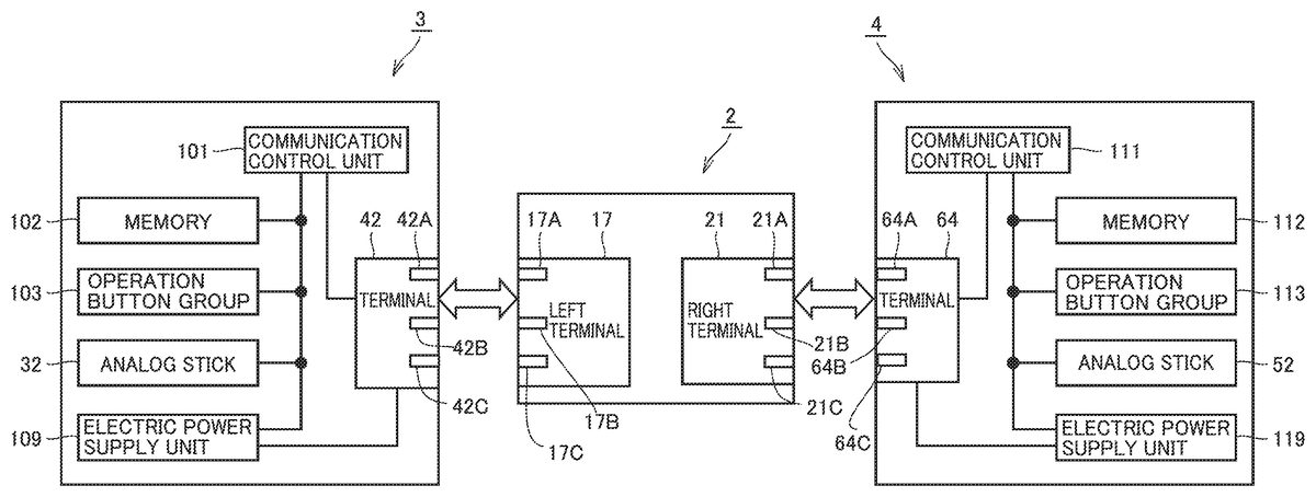
FIG. 8is an example non-limiting block diagram showing an internal configuration of left controller3and right controller4based on the present embodiment.
FIG. 8also depicts components of main body apparatus2associated with left controller3and right controller4.
Left controller3includes a communication control unit101for communication with main body apparatus2. Communication control unit101can communicate with main body apparatus2through both of wired communication through terminal42and wireless communication not through terminal42.
Terminal42includes a communication terminal42A used for communication, a power supply terminal42B used for power feed, and an identification terminal42C used for detection of a connected device.
Terminal42is provided as being connectable to left terminal17of main body apparatus2.
Left terminal17includes a communication terminal17A used for communication, a power supply terminal17B used for power feed, and an identification terminal17C used for detection of a connected device. When terminal42and left terminal17are connected to each other, communication terminal42A and communication terminal17A are electrically connected to each other. Power supply terminal42B and power supply terminal17B are electrically connected to each other. Identification terminal42C and identification terminal17C are electrically connected to each other.
Communication control unit101selects wired communication or wireless communication depending on whether or not left controller3is attached to main body apparatus2, and establishes communication under a selected communication method. While left controller3is attached to main body apparatus2, communication control unit101establishes communication with main body apparatus2through communication terminal42A. While left controller3is detached from main body apparatus2, communication control unit101establishes wireless communication with main body apparatus2(specifically, controller communication unit83). Communication control unit101should only be able to establish communication with main body apparatus2, and for example, it may be configured to establish only either wired communication or wireless communication. While left controller3is detached from main body apparatus2, wireless communication is established by way of example, however, wired communication may be established, for example, through a cable.
Left controller3includes, for example, a memory102such as a flash memory. Communication control unit101is implemented, for example, by a microprocessor and performs various types of processing by executing firmware stored in memory102.
Left controller3includes an operation button group103(specifically operation buttons33to36,38, and39) and analog stick32. Information on an operation onto operation button group103and analog stick32is repeatedly output to communication control unit101with a prescribed period.
Communication control unit101obtains information on an input from each of operation button group103and analog stick32(for example, information on an operation by a user). Communication control unit101transmits data including obtained information (or information obtained by subjecting obtained information to prescribed processing) to main body apparatus2. Data is transmitted to main body apparatus2repeatedly with a prescribed period. A period of transmission of information on an input to main body apparatus2may or may not be identical among input devices.
Main body apparatus2can know an input given to left controller3based on transmitted data. More specifically, main body apparatus2can discriminate an operation onto operation button group103and analog stick32.
Left controller3includes an electric power supply unit109including a battery. Electric power supply unit109controls supply of electric power to each component of left controller3. When left controller3is attached to main body apparatus2, the battery is charged by power feed from main body apparatus2through power supply terminal42B.
Right controller4is configured basically similarly to left controller3described above. Right controller4includes terminal64, a communication control unit111, a memory112, an operation button group113(specifically operation buttons53to56,60, and61), analog stick52, and an electric power supply unit119.
Since other components of right controller4have features and functions the same as those of corresponding components described in connection with left controller3, detailed description will not be repeated.
Terminal64includes a communication terminal64A used for communication, a power supply terminal64B used for power feed, and an identification terminal64C used for detection of a connected device.
Terminal64is provided as being connectable to right terminal21of main body apparatus2.
Right terminal21includes a communication terminal21A used for communication, a power supply terminal21B used for power feed, and an identification terminal21C used for detection of a connected device. When terminal64and right terminal21are connected to each other, communication terminal21A and communication terminal64A are electrically connected to each other. Power supply terminal21B and power supply terminal64B are electrically connected to each other. Identification terminal21C and identification terminal64C are electrically connected to each other.
Communication control unit111selects wired communication or wireless communication depending on whether or not right controller4is attached to main body apparatus2, and establishes communication under a selected communication method. When right controller4is attached to main body apparatus2, communication control unit111establishes communication with main body apparatus2through communication terminal64A.
Right controller4includes electric power supply unit119including a battery. Electric power supply unit119controls supply of electric power to each component of right controller4. While right controller4is attached to main body apparatus2, the battery is charged by power feed from main body apparatus2through power supply terminal64B.
When the controller is attached to main body apparatus2, a first terminal (that is, left terminal17or right terminal21) of main body apparatus2and a second terminal (that is, terminal42or64) of the controller are electrically connected to each other as abutting on each other.
When the controller is attached to main body apparatus2, whether or not connection is established is determined based on a connected identification terminal. Wired communication can be carried out through the connected communication terminal. Power can be fed through the connected power supply terminal.
The controller can also include a vibration mechanism, an acceleration sensor, and a gyro sensor.
[C. Connected Device]
(c1: Expansion Battery)
FIG. 9is an example non-limiting diagram illustrating an expansion battery200which can be connected to the controller based on an embodiment.
As shown inFIG. 9, expansion battery200is connected to left controller3. Expansion battery200is provided to be able to supply electric power to left controller3. Specifically, a terminal201which can electrically be connected to left controller3is provided in expansion battery200.
Terminal201includes a communication terminal201A used for communication, a power supply terminal201B used for power feed, and an identification terminal201C used for detection of a connected device. As terminal42and terminal201are connected to each other, communication terminal42A and communication terminal201A are electrically connected to each other. Power supply terminal42B and power supply terminal201B are electrically connected to each other. Identification terminal42C and identification terminal201C are electrically connected to each other.
An LED202indicating a state of charge to left controller3is provided in expansion battery200.
Similarly to left controller3, a terminal203which can electrically be connected to right controller4is provided in expansion battery200. Terminal203includes a communication terminal203A, a power supply terminal203B used for power feed, and an identification terminal203C used for detection of a connected device. As terminal64and terminal203are connected to each other, communication terminal64A and communication terminal203A are electrically connected to each other. Power supply terminal64B and power supply terminal203B are electrically connected to each other. Identification terminal64C and identification terminal203C are electrically connected to each other.
LED202emits light during charging of right controller4as in left controller3.
FIG. 10is an example non-limiting diagram illustrating a circuit configuration of left controller3and expansion battery200based on the embodiment.
As shown inFIG. 10, electric power supply unit109is provided in left controller3.
Electric power supply unit109includes a voltage detector105, a state-of-charge sensing unit106, a current regulator107, a resistor R1, a battery V1, a diode D1, and switches SW1and SW2.
A node N1is connected to identification terminal42C with resistor R1being interposed.
A node N0is connected to power supply terminal42B.
Diode D1has an anode connected to node NO and a cathode connected to node N1with current regulator107being interposed. Current regulator107is provided between diode D1and node N1.
Battery V1is connected between node N1and a ground voltage GND. Switch SW1is connected between a node N2and node NO. Switch SW2is connected between node N2and node N1. Voltage detector105is connected to node N0. Switches SW1and SW2are controlled in accordance with an instruction from communication control unit101.
Node N2is connected to a power supply line so that electric power necessary for each unit is supplied.
State-of-charge sensing unit106is provided in correspondence with battery V1, and senses a state of charge of battery V1and outputs the state of charge to communication control unit101.
Expansion battery200includes a battery V2, a diode D2, a resistor R2, LED202, and a switch SW3.
Resistor R2is connected between identification terminal201C and ground voltage GND.
Diode D2is connected in series between power supply terminal201B and a node N3. Diode D2has an anode connected to node N3and a cathode connected to power supply terminal201B. Battery V2is connected between node N3and ground voltage GND. Switch SW3and LED202are connected in series between node N3and ground voltage GND. Switch SW3is controlled in accordance with an instruction from communication control unit101.
Communication control unit101includes a discrimination unit120, a switch control unit122, a processing execution unit124, a communication unit126, and a light emission control unit128.
Discrimination unit120discriminates a device connected to terminal42based on a voltage value detected by voltage detector105. Discrimination unit120outputs a control signal CT for regulating a current to current regulator107.
Switch control unit122controls switching of switches SW1and SW2in accordance with a result of discrimination by discrimination unit120. For example, when no device is connected to terminal42, switch control unit122turns on switch SW2. Thus, battery V1is connected to the power supply line and electric power necessary for each unit is supplied. When discrimination as connection of a connected device is made in accordance with a result of discrimination by discrimination unit120while electric power necessary for each unit is supplied from battery V1, switch control unit122turns off switch SW2and turns on switch SW1. Battery V1and the power supply line are thus electrically connected and disconnected to and from each other. As switch SW1is turned on, terminal42and the power supply line are electrically connected to each other and power can be fed through terminal42.
Communication unit126performs processing for wireless communication and processing for wired communication with an external device.
Specifically, in the present embodiment, communication unit126transmits attachment information on another attached apparatus to main body apparatus2. In the present example, communication unit126transmits attachment information (an identification code) based on a result of discrimination by discrimination unit120to main body apparatus2. When another apparatus is not attached, communication unit126can also transmit attachment information (an identification code) indicating absence of attachment.
Processing execution unit124performs prescribed processing in accordance with an instruction from an external device received at communication unit126.
Light emission control unit128controls the LED provided in the device based on a result of discrimination by discrimination unit120and a result of sensing by state-of-charge sensing unit106. In the present example, a command to turn on switch SW3is output.
As a result of connection between terminal42and terminal201, identification terminal42C of left controller3and identification terminal201C of expansion battery200are electrically connected to each other. Power supply terminal42B of left controller3and power supply terminal201B of expansion battery200are electrically connected to each other. Communication terminal42A of left controller3and communication terminal201A of expansion battery200are electrically connected to each other.
In the present example, as a result of electrical connection between identification terminal42C and identification terminal201C, a current flows from battery V1through resistors R1and R2toward ground voltage GND. As a current path is formed, connection with a connected device is detected.
Voltage detector105detects a voltage based on division of resistances of resistor R1and resistor R2as a result of formation of the current path.
Discrimination unit120detects a connected device based on a detected voltage value and discriminates the connected device. In the present example, a resistance value of resistor R2is different depending on a type of a connected device connected to the controller. Therefore, a voltage value detected by voltage detector105is different depending on a type of a device.
Discrimination unit120instructs switch control unit122to switch based on a result of discrimination.
Switch control unit122gives an instruction to turn off switch SW2and turn on switch SW1. Accordingly, instead of battery V1, battery V2supplies electric power to each unit in left controller3.
Battery V1is chargeable and dischargeable. As switch SW is switched by switch control unit122, battery V1is charged as a result of supply of electric power from battery V2when electric power is supplied from battery V2to each unit in left controller3.
Current regulator107regulates a charging current in charging of battery V1from battery V2. Specifically, a charging current for battery V1is regulated in accordance with control signal CT from discrimination unit120.
Light emission control unit128outputs a command signal for having the LED emit light based on a result of discrimination by discrimination unit120and a result of sensing by state-of-charge sensing unit106. The command signal is input to switch SW3through communication terminal42A and communication terminal201A from communication control unit101.
Specifically, light emission control unit128outputs a command signal to turn on switch SW3when a connected device is discriminated as a device having an LED as a result of discrimination by discrimination unit120and battery V1is in a prescribed state of charge. The prescribed state of charge refers to battery V1not being fully charged by way of example. When battery V1is fully charged, battery V1is not charged by battery V2. In such a case, light emission control unit128does not output a command signal to turn on switch SW3and hence LED202does not emit light. Therefore, fully charged battery V1can easily be recognized. When light emission control unit128outputs a command signal to turn on switch SW3and LED202emits light, battery V1being charged can easily be recognized. For example, expansion battery200may be removed and attached from and to left controller3based on a state of emission of light by LED202. In the present example, light emission control unit128outputs a command signal for having the LED emit light based on a result of discrimination by discrimination unit120and a result of sensing by state-of-charge sensing unit106. A command signal for having the LED emit light only in accordance with a result of discrimination by discrimination unit120, however, may be output. Thus, a connection state can easily be checked.
A connected device described below is also similar in circuit configuration or in configuration of the battery and the LED to expansion battery200. A resistance value of resistor R2is different depending on a type of a connected device.
(c2: Expansion Grip300)
FIG. 11is an example non-limiting diagram of appearance of an expansion grip300based on the embodiment.
Expansion grip300for attaching left controller3and right controller4detached from main body apparatus2is shown inFIG. 11. Expansion grip300represents one example of a connected device to which a controller can be attached. Expansion grip300is a connected device with which a user performs an operation.
Expansion grip300includes a housing310. Left controller3and right controller4can be attached to housing310. Therefore, with expansion grip300, a user can perform an operation as integrally holding two controllers of left controller3and right controller4detached from main body apparatus2. Expansion grip300has a mechanism similar to the mechanism of main body apparatus2as the mechanism for attachment of the controller. Therefore, left controller3and right controller4can be attached to expansion grip300as in attachment of main body apparatus2.
Expansion grip300has a grip portion for a user to hold. Specifically, left controller3is attached to expansion grip300on the left of the center in the lateral direction. Expansion grip300includes a left grip portion301on the left of a portion where left controller3is attached. Right controller4is attached to expansion grip300on the right of the center in terms of the lateral direction. Expansion grip300includes a right grip portion302on the right of a portion where right controller4is attached. Therefore, a user can easily operate each of left controller3and right controller4attached to expansion grip300by holding grip portions301and302.
Expansion grip300has a left terminal303similar to left terminal17of main body apparatus2at a position where connection with terminal42of left controller3attached to the expansion grip itself can be made. Expansion grip300has a right terminal304similar to right terminal21of main body apparatus2at a position where connection with terminal64of right controller4attached to the expansion grip itself can be made. Therefore, when left controller3and right controller4are attached to expansion grip300, expansion grip300is electrically connected to left controller3and right controller4.
Left terminal303and right terminal304each include a communication terminal, a power supply terminal, and an identification terminal which can be connected to the communication terminal, the power supply terminal, and the identification terminal of terminals42and64, respectively, similarly to terminals201and203of expansion battery200.
Therefore, when the controller and expansion grip300are connected to each other, communication and supply of electric power therebetween can be enabled. Though not shown, expansion grip300includes a power supply terminal similar to a power supply terminal of cradle5. Therefore, expansion grip300can receive power feed through the power supply terminal from a not-shown charging apparatus (such as an AC adapter) when the charging apparatus is connected to the power supply terminal. Expansion grip300supplies electric power supplied through the power supply terminal to left controller3and right controller4through the left terminal and the right terminal.
Therefore, by connecting expansion grip300to the charging apparatus, left controller3and right controller4attached to expansion grip300can be charged. As set forth above, expansion grip300has a function to charge the controller attached to the expansion grip itself. Expansion grip300includes charging means (that is, the power supply terminal and the left terminal or the right terminal) for charging the controller attached to expansion grip300with electric power fed to expansion grip300. Thus, the controller can be charged while the controller is attached to the expansion grip. Thus, convenience of the controller can be improved. When left controller3and right controller4are attached to expansion grip300, wireless communication is established between each of left controller3and right controller4and main body apparatus2(as in the example in which left controller3and right controller4are detached from main body apparatus2). Even while the controller is attached to expansion grip300, left controller3and right controller4can communicate with main body apparatus2.
Expansion grip300contains a microcomputer (CPU)320and a communication unit330. Left controller3and right controller4obtain apparatus identification information indicating attachment to expansion grip300, which is transmitted from microcomputer320through communication unit330, when the controller is attached to expansion grip300. The apparatus identification information is, for example, identification information provided for each apparatus (more specifically, identification information specific to an apparatus). In the present embodiment, the apparatus identification information includes information indicating a type of an apparatus so that a type of the apparatus can be specified based on the apparatus identification information.
The controller can determine (or sense) that an apparatus to which the controller is attached is expansion grip300, that is, attachment of the controller itself to expansion grip300, based on the identification information. When the controller is detached from expansion grip300, the controller transmits a notification about detachment from expansion grip300through wireless communication to main body apparatus2.
(c3: Trial Play Stand Expansion Battery)
FIG. 12is an example non-limiting diagram illustrating a trial play stand expansion battery400which can be connected to the controller based on the embodiment.
As shown inFIG. 12, trial play stand expansion battery400is connected to left controller3. Trial play stand expansion battery400is provided to be able to supply electric power to left controller3.
Specifically, trial play stand expansion battery400is provided with a terminal401which can electrically be connected to left controller3.
Terminal401includes a power supply terminal401B used for power feed and an identification terminal401C used for detection of a connected device. As a result of connection between terminal42and terminal401, power supply terminal42B and power supply terminal401B are electrically connected to each other. Identification terminal42C and identification terminal401C are electrically connected to each other.
Trial play stand expansion battery400is provided with a terminal403which can electrically be connected to right controller4. Terminal403includes a power supply terminal403B used for power feed and an identification terminal403C used for detection of a connected device. As a result of connection between terminal64and terminal403, power supply terminal64B and power supply terminal403B are electrically connected to each other. Identification terminal64C and identification terminal403C are electrically connected to each other.
Trial play stand expansion battery400is connected to an AC plug terminal402and an AC adapter404. AC plug terminal402can be connected to a connector of an AC power supply. AC adapter404converts AC power supply to DC power supply so as to supply electric power to trial play stand expansion battery400. According to such a configuration, trial play stand expansion battery400can constantly receive power feed from the AC power supply. Trial play stand expansion battery400supplies electric power to left controller3and right controller4through terminal401and/or terminal403.
(c4: Fixed Expansion Battery)
FIG. 13is an example non-limiting diagram illustrating a fixed expansion battery500which can be connected to a plurality of controllers based on the embodiment.
As shown inFIG. 13, fixed expansion battery500is provided to be able to supply electric power to a plurality of controllers. In the present example, two left controllers3and two right controller4can be connected. Fixed expansion battery500is provided to be able to supply electric power to a plurality of left controllers3and a plurality of right controllers4.
Terminals501and511which can be connected to left controller3and terminals503and513which can be connected to right controller4are provided. Terminals501,511,503, and513are connected to an electric power supply unit510provided with a battery.
Each terminal includes a communication terminal, a power supply terminal, and an identification terminal which can be connected to the communication terminal, the power supply terminal, and the identification terminal, respectively, of terminal42or64, similarly to terminal201or203of expansion battery200.
Therefore, when the controller and fixed expansion battery500are connected to each other, communication and supply of electric power therebetween can be enabled. Though not shown, fixed expansion battery500includes a power supply terminal similar to the power supply terminal of cradle5. Therefore, fixed expansion battery500can receive power feed through the power supply terminal from a not-shown charging apparatus (such as an AC adapter) by connecting the charging apparatus to the power supply terminal. Fixed expansion battery500supplies electric power supplied through the power supply terminal to left controller3and right controller4through the terminal.
A plurality of LEDs indicating a state of charge are provided in fixed expansion battery500. Specifically, the fixed expansion battery includes an LED502indicating a state of charge of the controller connected to terminal501, an LED504indicating a state of charge of the controller connected to terminal503, an LED506indicating a state of charge of the controller connected to terminal511, and an LED508indicating a state of charge of the controller connected to terminal513.
Emission of light from the LED is controlled under a scheme the same as above through the communication terminal used for communication.
[D. Processing]
FIG. 14is an example non-limiting diagram illustrating a discrimination table used by discrimination unit120based on the embodiment.
As shown inFIG. 14, a discrimination table may be stored in advance in memories102and112. The discrimination table is provided with a plurality of pieces of identification information ID0to ID4(identification codes). A voltage value, an amount of a charging current, a notification about charging, and an exemplary device are set in association with identification information. The exemplary device is given as an item for illustration and such information does not have to be stored.
By way of example, a voltage value (P0to P1), an amount of a charging current Q1, a notification about charging (no), and an exemplary device (a main body and an expansion grip) are set in association with identification information ID0.
A voltage value (P1to P2), amount of a charging current Q1, a notification about charging (no), and an exemplary device (a trial play stand expansion battery) are set in association with identification information ID1.
A voltage value (P2to P3), an amount of a charging current Q2(<Q1), a notification about charging (yes), and an exemplary device (a fixed expansion battery) are set in association with identification information ID2.
A voltage value (P3to P4), amount of a charging current Q1, a notification about charging (yes), and an exemplary device (an expansion battery) are set in association with identification information ID3.
Identification information ID4is an item indicating connection of no device, and nothing is set as a voltage value, an amount of a charging current, a notification about charging, and an exemplary device.
In the present embodiment, a connected device connected to a controller is identified based on a result of detection by voltage detector105described above. A resistance value of resistor R2described with reference toFIG. 10is different for each device. Specifically, resistor R2of each of main body apparatus2and expansion grip300is set to have a resistance value at which a voltage value within a range from P0to P1is detected in attachment to the controller.
Resistor R2of trial play stand expansion battery400is set to have a resistance value at which a voltage value within a range from P1to P2is detected in attachment to the controller.
Resistor R2of fixed expansion battery500is set to have a resistance value at which a voltage value within a range from P2to P3is detected in attachment to the controller.
Resistor R2of expansion battery200is set to have a resistance value at which a voltage value within a range from P3to P4is detected in attachment to the controller.
(d1: Processing by Controller When Expansion Battery200is Attached)
Voltage detector105detects a voltage value within the range from P3to P4when expansion battery200is connected to the controller.
Discrimination unit120identifies a connected device as the expansion battery corresponding to identification information ID3by using the discrimination table based on the voltage value.
Discrimination unit120instructs switch control unit122to switch conducting switch SW2to switch SW1based on a result of discrimination. Accordingly, the controller operates by receiving power feed from expansion battery200.
Discrimination unit120outputs control signal CT to current regulator107such that amount of a charging current Q1is attained based on a result of discrimination. Thus, current regulator107regulates the amount of the charging current in charging of the battery of the controller from expansion battery200.
Light emission control unit128controls LED202provided in expansion battery200based on a result of discrimination by discrimination unit120and a result of sensing by state-of-charge sensing unit106. Specifically, since the item of the notification about charging corresponding to identification information ID3indicates “yes”, light emission control unit128recognizes that an LED for giving a notification about charging is provided. Then, when light emission control unit128determines that battery V1is fully charged based on a result of sensing by state-of-charge sensing unit106, it does not output a command signal to turn on switch SW3. When light emission control unit128determines that battery V1is not fully charged based on a result of sensing by state-of-charge sensing unit106, it outputs a command signal to turn on switch SW3. Accordingly, LED202emits light.
Communication unit126transmits identification information ID3to main body apparatus2as a result of discrimination by discrimination unit120. Controller communication unit83of main body apparatus2obtains identification information ID3transmitted from communication unit126. Then, the information is given from controller communication unit83of main body apparatus2to CPU81. CPU81can recognize connection of expansion battery200to the controller in accordance with obtained identification information ID3. On the side of main body apparatus2, CPU81performs information processing upon receiving the information.
CPU81can perform prescribed representation processing by way of example of information processing. Specifically, information on expansion battery200may be shown on display12in accordance with identification information ID3. CPU81may adjust a parameter for operation data transmitted from the controller by way of another example of information processing, because operational feeling of the controller may be different between before and after connection of expansion battery200.
Main body apparatus2may instruct the controller to perform prescribed processing depending on a recognized connected device. For example, by way of example, CPU81may give an instruction to change some of functions of the controller in accordance with obtained identification information ID3. For example, CPU81may output an order to stop a vibration mechanism when the controller is provided with the vibration mechanism.
Communication unit126of the controller receives the order and outputs the order to processing execution unit124. Processing execution unit124may change to setting for not using the vibration mechanism based on the order transmitted from main body apparatus2.
Since the function of the controller can be changed under the control by main body apparatus2depending on a type of a connected device, usability can be improved.
(d2: Processing by Controller When Expansion Grip300is Attached)
When expansion grip300is connected to the controller, voltage detector105detects a voltage value within the range from P0to P1.
When the controller is connected to expansion grip300, the controller obtains apparatus identification information from microcomputer320of expansion grip300through communication unit330.
Discrimination unit120identifies a connected device as an expansion grip corresponding to identification information ID0based on the detected voltage value and the apparatus identification information (identification information specific to the expansion grip) by using the discrimination table.
In the present example, discrimination unit120identifies a connected device as the expansion grip corresponding to identification information ID0based on the detected voltage value and the apparatus identification information, however, determination may be made based on any one of them.
Discrimination unit120instructs switch control unit122to switch conducting switch SW2to switch SW1based on a result of discrimination. Accordingly, the controller operates by receiving power feed from expansion grip300.
Discrimination unit120outputs control signal CT to current regulator107such that amount of a charging current Q1is attained based on a result of discrimination. Thus, current regulator107regulates the amount of the charging current in charging of the battery of the controller from expansion grip300.
Since expansion grip300is provided with no LED, light emission control unit128does not output a command signal.
Communication unit126transmits identification information ID0and apparatus identification information to main body apparatus2as a result of discrimination by discrimination unit120. Controller communication unit83of main body apparatus2obtains identification information ID0and the apparatus identification information transmitted from communication unit126. Then, the information is given from controller communication unit83of main body apparatus2to CPU81. CPU81can recognize connection of expansion grip300to the controller in accordance with obtained identification information ID0and the apparatus identification information. On the side of main body apparatus2, CPU81can perform information processing as described above upon receiving the information.
When expansion grip300is connected to the controller, main body apparatus2can easily discriminate that the device contains the microcomputer because apparatus identification information from microcomputer320is obtained.
(d3: Processing by Controller When Trial Play Stand Expansion Battery400is Attached)
Voltage detector105detects a voltage value within the range from P1to P2when trial play stand expansion battery400is connected to the controller.
Discrimination unit120identifies a connected device as an expansion battery corresponding to identification information ID1by using the discrimination table based on the voltage value.
Discrimination unit120instructs switch control unit122to switch conducting switch SW2to switch SW1based on a result of discrimination. Accordingly, the controller operates by receiving power feed from trial play stand expansion battery400.
Discrimination unit120outputs control signal CT to current regulator107such that amount of a charging current Q1is attained based on a result of discrimination. Thus, current regulator107regulates the amount of the charging current in charging of the battery of the controller from trial play stand expansion battery400.
Since trial play stand expansion battery400is provided with no LED, light emission control unit128does not output a command signal.
Communication unit126transmits identification information ID1to main body apparatus2as a result of discrimination by discrimination unit120. Controller communication unit83of main body apparatus2obtains identification information ID1transmitted from communication unit126. Then, the information is given from controller communication unit83of main body apparatus2to CPU81. CPU81can recognize connection of trial play stand expansion battery400to the controller in accordance with obtained identification information ID1. On the side of main body apparatus2, CPU81can perform information processing as described above upon receiving the information.
(d4: Processing by Controller When Fixed Expansion Battery500is Attached)
Voltage detector105detects a voltage value within the range from P2to P3when fixed expansion battery500is connected to the controller.
Discrimination unit120identifies a connected device as the fixed expansion battery corresponding to identification information ID2by using the discrimination table based on the voltage value.
Discrimination unit120instructs switch control unit122to switch conducting switch SW2to switch SW1based on a result of discrimination. Accordingly, the controller operates by receiving power feed from fixed expansion battery500.
Discrimination unit120outputs control signal CT to current regulator107such that amount of a charging current Q2is attained based on a result of discrimination. Thus, current regulator107regulates the amount of the charging current in charging of the battery of the controller from fixed expansion battery500.
In the present example, amount of charging current Q2is set to a value smaller than amount of charging current Q1. Since fixed expansion battery500is provided to be able to charge a plurality of controllers, the amount of the charging current is set to a value smaller than amount of charging current Q1in order to appropriately distribute a current.
Light emission control unit128controls a corresponding LED provided in fixed expansion battery500based on a result of discrimination by discrimination unit120and a result of sensing by state-of-charge sensing unit106. Specifically, since the item for the notification about charging corresponding to identification information ID2indicates “yes”, light emission control unit128recognizes that an LED for giving a notification about charging is provided. Then, when light emission control unit128determines that battery V1is fully charged based on a result of sensing by state-of-charge sensing unit106, it does not output a command signal for turning on switch SW3. When light emission control unit128determines that battery V1is not fully charged based on a result of sensing by state-of-charge sensing unit106, it outputs a command signal for turning on switch SW3. Accordingly, a corresponding LED emits light.
Communication unit126transmits identification information ID2to main body apparatus2as a result of discrimination by discrimination unit120. Controller communication unit83of main body apparatus2obtains identification information ID2transmitted from communication unit126. Then, the information is given from controller communication unit83of main body apparatus2to CPU81. CPU81can recognize connection of fixed expansion battery500to the controller in accordance with obtained identification information ID2. On the side of main body apparatus2, CPU81can perform information processing as described above upon receiving the information.
Through the processing, discrimination unit120can identify a connected device connected to the controller with a simplified scheme based on a result of detection by voltage detector105.
While certain example systems, methods, devices, and apparatuses have been described herein, it is to be understood that the appended claims are not to be limited to the systems, methods, devices, and apparatuses disclosed, but on the contrary, are intended to cover various modifications and equivalent arrangements included within the spirit and scope of the appended claims.
Claims
- A game system comprising: a game controller;a connected device connected to the game controller;and a main body apparatus, the connected device including a first battery for supplying electric power to the game controller, a first terminal electrically connected to the game controller, and a resistor connected to the first terminal, the game controller including a controlled component, a second battery for supplying electric power to the controlled component, a second terminal electrically connected to the connected device, a voltage detecting circuit detecting a voltage value in accordance with a current which flows through the resistor when the first terminal and the second terminal are connected to each other, and a control circuit, wherein the control circuit discriminates a device connected to the game controller based on a voltage value detected by the voltage detecting circuit, switches from the second battery to the first battery for supply of electric power to the controlled component when the discriminated device is the connected device while electric power is supplied from the second battery to the controlled component, and transmits a result of discrimination to the main body apparatus, and wherein the control circuit transmits the result of discrimination to the main body apparatus through wireless communication.
- The operation system according to claim 1 , wherein the connected device includes a light emitter emitting light in accordance with a result of discrimination by the control circuit.
- The operation system according to claim 2 , wherein the game controller includes a light emission control circuit controlling the light emitter to emit light when the device discriminated by the control circuit is the connected device.
- The operation system according to claim 3 , wherein the second battery is configured to be charged through supply of electric power from the first battery as switching from the second battery to the first battery is made by the control circuit.
- The operation system according to claim 4 , wherein the light emission control circuit determines whether a state of charge of the second battery is equal to or higher than a prescribed level, and has the light emitter emit light when the light emission control circuit determines that the state of charge of the second battery is not equal to or higher than the prescribed level.
- The operation system according to claim 1 , the operation system comprising another connected device different from the connected device, wherein the another connected device further includes a microcomputer, a third terminal electrically connected to the game controller, and a device communication circuit transmitting identification information of the another connected device itself to the game controller from the microcomputer through the third terminal, and the control circuit of the game controller discriminates a device connected to the game controller based on any of the transmitted identification information and the voltage value detected by the voltage detecting circuit.
- The game system according to claim 1 , wherein the main body apparatus includes an information processing circuit performing information processing based on the result of discrimination by the control circuit.
- The game system according to claim 7 , wherein the information processing circuit displays, on a display, information on the device connected to the game controller and discriminated based on the result of discrimination by the control circuit.
- A game controller configured to be connected to a connected device including a first battery configured to supply electric power and a first terminal for supplying electric power from the first battery, the game controller comprising: a controlled component;a second battery for supplying electric power to the controlled component;a second terminal for electrical connection to the connected device;a voltage detecting circuit detecting a voltage value in accordance with a current which flows through a resistor provided in the connected device when the first terminal and the second terminal are connected to each other;and a control circuit, wherein the control circuit discriminates a device connected to the game controller based on a voltage value detected by the voltage detecting circuit;and switches from the second battery to the first battery for supply of electric power to the controlled component when the discriminated device is the connected device while electric power is supplied from the second battery to the controlled component, and wherein the control circuit transmits a result of discrimination to a main body apparatus through wireless communication.
- The game controller according to claim 9 , the game controller further comprising a light emission control circuit controlling a light emitter provided in the connected device to emit light when the device discriminated by the control circuit is the connected device.
- The game controller according to claim 10 , wherein the second battery is configured to be charged through supply of electric power from the first battery as switching from the second battery to the first battery is made by the control circuit.
- The game controller according to claim 11 , wherein the light emission control circuit determines whether a state of charge of the second battery is equal to or higher than a prescribed level, and controls the light emitter to emit light when the device discriminated by the control circuit is the connected device and the light emission control circuit determines that the state of charge of the second battery is not equal to or higher than the prescribed level.
- The game controller according to claim 9 , wherein the control circuit receives an instruction from the main body apparatus based on the result of discrimination, and performs prescribed processing in accordance with the instruction received from the main body apparatus.
- The game controller according to claim 9 , the game controller further comprising a memory storing a table in which identification information for identifying a connected device and a voltage value are brought in correspondence with each other, wherein the control circuit discriminates a device connected to the game controller with reference to the table stored in the memory, based on the voltage value detected by the voltage detecting circuit.
- The game controller according to claim 9 , wherein the game controller is configured to be connected to another connected device different from the connected device, wherein the another connected device includes a microcomputer, a third terminal electrically connected to the game controller, and a device communication circuit transmitting identification information of the another connected device itself to the game controller from the microcomputer through the third terminal, and the control circuit discriminates a device connected to the game controller based on any of the transmitted identification information and the voltage value detected by the voltage detecting circuit.
Disclaimer: Data collected from the USPTO and may be malformed, incomplete, and/or otherwise inaccurate.