U.S. Pat. No. 10,099,119
TOUCH SCREEN INPUTS FOR A VIDEO GAME SYSTEM
AssigneeNintenco Co., Ltd.
Issue DateJune 12, 2017
Illustrative Figure
Abstract
Example systems and methods involve detecting an input to a touchscreen display of a video game apparatus; determining a video game action based on a shape of the input; and determining a timing of the video game action based on a color associated with the input.
Description
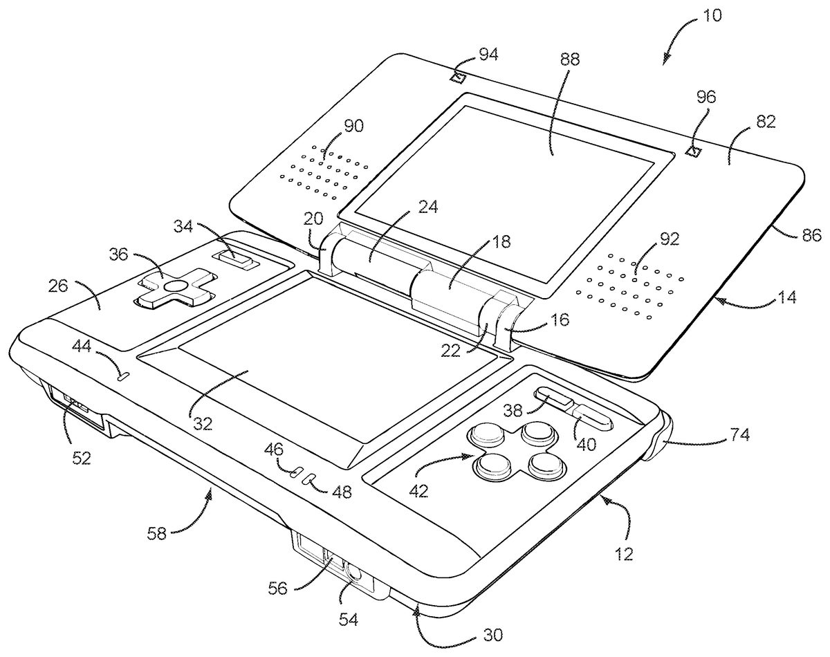
DETAILED DESCRIPTION OF EXAMPLE EMBODIMENTS Referring toFIGS. 1 and 2, in an illustrative embodiment the game system10includes a main body12and a cover body14hingedly connected to each other along an upper edge of the main body12and a lower edge of the cover body14(references herein to terms such as “upper” and “lower” and “forward” and “rearward” are for ease of understanding and are made relative to an orientation of the game device where the cover body14is in an open position and the game is being held by a user in a normal operating position). Hinge elements16,18and20on the main body12mesh with hinge elements22and24on the cover body, with a hinge pin (not shown) extending through the aligned hinge elements in conventional fashion. Note that because hinge elements16,18and20extend from the upper (or inner) face26of the main body12, the cover body14overlies the upper face26when the cover body14is closed over the main body. When the cover body14is in its fully open position, it is substantially parallel to the main body12but lies in a substantially parallel, offset plane. The main body12also has a lower (or outer) face28(FIG. 2) and a peripheral edge30. A first display screen32is recessed within the upper face26of the main body12with dimensions of approximately 2 inches in length and 1⅞ inches in width, yielding a diagonal screen dimension of 3 inches. The screen in the exemplary embodiment is a backlit (e.g., 40 candelas), color liquid crystal display (LCD) with a display resolution of 256×192 dots (aspect ratio 4:3). This screen is touch sensitive and may be activated by a stylus, described further herein. A power button34is located in the upper left corner of face26and is used to turn the game on and off. A cross-shaped directional control button36is located adjacent and below the power button34, and is used for game play control. More specifically, display ...
DETAILED DESCRIPTION OF EXAMPLE EMBODIMENTS
Referring toFIGS. 1 and 2, in an illustrative embodiment the game system10includes a main body12and a cover body14hingedly connected to each other along an upper edge of the main body12and a lower edge of the cover body14(references herein to terms such as “upper” and “lower” and “forward” and “rearward” are for ease of understanding and are made relative to an orientation of the game device where the cover body14is in an open position and the game is being held by a user in a normal operating position). Hinge elements16,18and20on the main body12mesh with hinge elements22and24on the cover body, with a hinge pin (not shown) extending through the aligned hinge elements in conventional fashion. Note that because hinge elements16,18and20extend from the upper (or inner) face26of the main body12, the cover body14overlies the upper face26when the cover body14is closed over the main body. When the cover body14is in its fully open position, it is substantially parallel to the main body12but lies in a substantially parallel, offset plane. The main body12also has a lower (or outer) face28(FIG. 2) and a peripheral edge30.
A first display screen32is recessed within the upper face26of the main body12with dimensions of approximately 2 inches in length and 1⅞ inches in width, yielding a diagonal screen dimension of 3 inches. The screen in the exemplary embodiment is a backlit (e.g., 40 candelas), color liquid crystal display (LCD) with a display resolution of 256×192 dots (aspect ratio 4:3). This screen is touch sensitive and may be activated by a stylus, described further herein. A power button34is located in the upper left corner of face26and is used to turn the game on and off. A cross-shaped directional control button36is located adjacent and below the power button34, and is used for game play control.
More specifically, display screen32includes a resistive-membrane touch panel that allows coordinates to be obtained in dot units. The touch panel can be operated with a finger or a stylus.
In the upper right corner of the main body12, there are side-by-side “start” and “select” buttons38,40, respectively, with X/Y/A/B buttons42located adjacent and below the “start” and select” buttons. Buttons38,40and42are also used for game play control. A microphone44(which may be an omni-directional condenser microphone) is located below the left edge of screen32for use with specially designed games having a microphone feature. A battery recharge indicator LED46and a power indicator LED48are also located on the upper face26, adjacent the lower edge thereof, below the right edge of screen32.
With reference now especially toFIG. 3, a lower or forward portion50of the peripheral edge30(closest to the user) is provided with a volume control slide52and headphone and microphone connectors54,56on either side of a first game slot58. Slot58is especially designed for larger game cartridges or cards originally designed for use with the assignee's Game Boy Advance® game system.
As best seen inFIG. 2, an upper or rearward portion60of the peripheral edge30is provided with an external extension connector62that permits connection to an AC adapter for recharging the internal battery (not shown), or for operating the game using household power. A second game slot64in edge portion60is designed for receiving memory or game cards especially designed for this game device. The second game slot64is smaller than the first game slot58, reflecting the different sizes of the game cards. Openings66,68form an elbow-shaped through slot adapted for securing a wrist strap (not shown), thereby enabling the user to secure the game device to the body and thus minimize the potential for losing or misplacing the game. A stylus port or holder, in the form of a blind bore70is located adjacent the wrist-strap mount for holding a stylus71(FIG. 5) before or after use.
The stylus71is a plastic pencil-shaped device with a rounded tip73and is used to activate the touch screen32.
A pair of left, right control buttons (or shoulder buttons)72,74are located on the peripheral edge30, at the corners where the upper portion60of the peripheral edge30meets the side portions76,78of the peripheral edge. The location of these buttons and the location of previously described buttons34,36and42facilitate manipulation game control by the user's thumbs and index fingers when the game is held with two hands in a natural and intuitive manner.
The lower (or outer) face28of the main body is provided with a battery cover80(FIG. 2) for accessing a rechargeable battery pack located within the main body.
The cover body14also has an upper (or inner) face82(FIG. 1) and a lower (or outer) face84(FIG. 2) connected by a peripheral edge86. The upper face82incorporates a second display screen88of substantially the same dimensions as screen32. Screen88is also a backlit color LCD. The cover body14also incorporates a pair of stereo speakers, with speaker grills90,92located on opposite sides of the screen88. Dimples or pads94,96may be located above and laterally of screen88. The dimples may be made of a compressible polymer or other suitable material and serve to dampen engagement of the inner surface82of the cover body14with the inner surface26of the main body12when the cover body is closed over the main body.
As already noted, the game card slot58is sized and adapted to receive a conventional game card designed for the by now well known Nintendo Gameboy Advance System®. Accordingly, the game card per se for slot58does not form any part of this invention and need not be described further.
FIG. 6is an illustration showing an example internal configuration of the portable game system10. As shown inFIG. 6, the portable game system10includes a CPU (central processing unit)223, which is an example of a computer for executing the game program, and other components. The CPU223is connected to a work RAM (working storage unit)224, a GPU (graphic processing unit)222, and a peripheral circuit I/F (interface)225. The work RAM224is a memory for temporarily storing, for example, the game program to be executed by the CPU223and calculation results of the CPU223. The GPU222uses, in response to an instruction from the CPU223, a VRAM221to generate a game image for display output to a first LCD (liquid crystal display unit)211and a second LCD212, and causes the generated game image to be displayed on the first display screen32of the first LCD211and the second display screen88of the second LCD212. The peripheral circuit I/F225is a circuit for transmitting and receiving data between external input/output units, such as the touch panel213, the operation keys214, the loudspeaker215, and the wireless communication circuit216, and the CPU223. The touch panel213(including a device driver for the touch panel) outputs coordinate data corresponding to a position input (specified) with the stylus71. The wireless communication circuit216may be configured for wireless communication in accordance with any of various known wireless protocols such as Bluetooth; any type of 802.11 (Wi-Fi) protocol; HiperLAN/1 protocol; HiperLAN/2 protocol; HomeRF protocol; etc. Although shown as a single block, wireless communication circuit216is intended to encompass arrangements in which two or more different protocols are usable or two or more different circuits (e.g., one for short-range communications such as WiFi and another for long-range communications using, for example, wireless telephone protocols) are provided. Of course, the example portable game system is not limited to wireless communication and may alternatively or additionally include circuitry that provides a wired communication link, e.g., to an internet access point.
To access the internet using the portable game system, wireless communication circuit216may, for example, wirelessly connect to an internet access point. Such an access point may be in a public location (e.g., stores, malls, libraries, etc.) or may be in a user's home (e.g., a cable modem).
The CPU223is electrically connected to the external memory I/F226, in which the cartridge217is inserted via slot64. The cartridge217is a storage medium for storing the game program and, specifically, includes a program ROM217afor storing the game program and a backup RAM217bfor rewritably storing backup data. The game program stored in the program ROM217aof the cartridge217is loaded to the work RAM224and is then executed by the CPU223. In the present embodiment, an exemplary case is described in which the game program is supplied from an external storage medium to the portable game system10. However, the game program may be stored in a non-volatile memory incorporated in advance in the portable game system10, or may be supplied to the portable game system10via a wired or wireless communication circuit.
FIG. 7is a block diagram of an example arrangement of the GPU222. The GPU222includes two image processing units, that is, a three-dimensional image processing unit231and a two-dimensional image processing unit237. The three-dimensional image processing unit231includes a geometry engine241for calculating each vertex of a three-dimensional model based on three-dimensional model data and a rendering engine242for generating a game image from the three-dimensional model disposed on a virtual three-dimensional game space. The two-dimensional image processing unit237includes a 2D rendering engine243for generating a game image based on two-dimensional image data representing characters and two-dimensional image data representing backgrounds. More specifically, the two-dimensional image processing unit237disposes a two-dimensional image representing a character on a virtual screen called a “sprite” and a two-dimensional image representing a background on a virtual screen called a “screen”, and then synthesizes these virtual screens to generate a game image to be eventually displayed.
The three-dimensional image processing unit231is connected to the 3D line buffer232. The 3D line buffer232is a buffer memory for temporarily retaining image data for one scanning line of the first LCD211(or the second LCD212). The image data generated by the three-dimensional image processing unit231is stored in this 3D line buffer232sequentially by one line.
The 3D line buffer232is connected to a capture circuit233and an LCD selector (SEL LCD)235. The capture circuit233sequentially reads image data for one line stored in the 3D line buffer232and then sequentially stores the read image data in the VRAM221, which will be described further below, thereby capturing the game image generated by the three-dimensional image processing unit231.
The capture circuit233is connected to a VRAM selector (SEL VRAM)234. The VRAM221is provided with two VRAMs, that is, a first VRAM221aand a second VRAM221b. Instead of these two first and second VRAMs221aand221b, a single VRAM may be used with its two different storage areas being used as the first VRAM221aand the second VRAM221b. The VRAM selector234switches an output destination of the capture circuit233between the first VRAM221aand the second VRAM221b.
The first VRAM221aand the second VRAM221bare connected to a VRAM selector (SEL VRAM)236. The VRAM selector236switches a source of data to the two-dimensional image processing unit237between the first VRAM221aand the second VRAM221b.
The two-dimensional image processing unit237is connected to a 2D line buffer238. As with the 3D line buffer232, the 2D line buffer238is a buffer memory for temporarily retaining image data for one scanning line of the second LCD212. The image data generated by the two-dimensional image processing unit237is stored in this 2D line buffer238sequentially by one line.
The 2D line buffer238is connected to an LCD selector235. The LCD selector235switches an output destination of the 3D line buffer232between the first LCD211and the second LCD212, and an output destination of the 2D line buffer238between the first LCD211and the second LCD212. In the present embodiment, the LCD selector235performs control such that, when the output of the 3D line buffer232is supplied to the first LCD11, the output of the 2D line buffer38is supplied to the second LCD212, and when the output of the 3D line buffer232is supplied to the second LCD212, the output of the 2D line buffer238is supplied to the first LCD211.
Additional information regarding portable game system10may be found in application Ser. No. 11/111,985 filed Apr. 22, 2005 and Ser. No. 10/921,957, filed Aug. 20, 2004, the contents of which are incorporated herein in their entirety.
Generally speaking, inputs used to control game play have conventionally been provided by a user actuating devices such as a cross-switch, a joystick, various buttons, and the like. The provision of a game system with a touch screen such as display screen32permits additional inputs that can be used to enhance the gaming experience. For example, a user or player can draw shapes, symbols and characters onto the touch screen32. The application currently being executed by the game system e.g., a game) recognizes the input and then interprets the input for controlling the application.
By way of example without limitation, CPU223is supplied with coordinate data from touchscreen panel213when the stylus71(or a user's finger) is used to draw on the touchscreen panel. The coordinate data may be compared with pre-stored shapes, symbols and characters to determine the shape drawn on the touchscreen panel. As noted, the application currently being executed by the game interprets the determined shape, symbol or character for controlling the application.
Example shape, symbols and characters and possible instructions for a game include, but are not limited to:circles (seeFIG. 8A), which can be drawn to “select” and “highlight” objects on the screen;arrows (seeFIG. 8B), which can be drawn on the screen to tell game objects (e.g., characters) to move in the direction of the arrow;X's (seeFIG. 8C), which can be drawn to indicate a target to hit or a target destination to go to;lines (seeFIG. 8D), which can be drawn to create a barrier or border that an object cannot pass; anddots (seeFIG. 8I), which can be drawn to indicate where to hit (e.g., a game character(s)).
Other more complicated shapes and symbols such as stars (SeeFIG. 8E), swirls (seeFIG. 8F), the infinity symbol (seeFIG. 8G), wavy lines (seeFIG. 8H), dotted lines (seeFIG. 8J), triangles, question marks, hearts, etc. may be drawn and associated with commands for the game program. Such shapes, symbols and characters can generally be drawn without lifting the stylus from the touch screen surface and are sufficiently distinct from each other so that the game can recognize what has been drawn and take appropriate actions in response thereto.
The inputting of such shapes, symbols and characters can be implemented in a wide variety of games. For example, in a football game, users can draw their own plays and have their teams execute those plays. For example, prior to each play, a map of the field may be drawn for all team users to see. One user may move players into formation by drawing their positions on the touchscreen, and drawing their selected movement pattern as well by drawing arrows on the touchscreen from their formation position to their target position. Once the ball is snapped, this information can be displayed for each player on the team—they can see in 3D view the arrow drawn for their target path.
These plays can be created in advance and stored in memory for selection during the game or a new play can be created during the game to take into account a particular game situation. For example,FIGS. 9A and 9Bshow two plays in which paths with arrows on the end are drawn to move offensive players (indicated by circles). Similar plays may be developed in which defensive players are moved in accordance with paths drawn using the touchscreen. In other implementations, the touchscreen may be used to develop various offensive and defensive formations and paths may be drawn to move the players from these initial formations. When an offensive player chooses to use a particular formation (e.g., by selection of an offensive formation previously specified by that user and stored in memory or by drawing the formation on the touch screen), the game program may be configured to recognize the formation and select for, or suggest to, the defensive player a particular defensive formation from among various defensive formations previously specified by that user and stored in memory.
Obviously, touchscreen inputs like those described above may be used to position and move players in other sports video games including baseball, hockey, soccer, basketball, etc. Additional inputs may be designated in accordance with the type of game. For example, inputs for a baseball game may be used, for example, to designate pitch location and type (e.g., straight line for fast ball, curved line for curve ball, etc.).
The above touchscreen inputs can also be used in tactical and military video games. For example, the touchscreen inputs may be used to specify the movement of the soldier game character in a field of battle. The inputs may also be used to specify the movement of a military vehicle game object (e.g., tank) in a field of battle.
Various tactical games may use the touchscreen to permit users or players to plan out attacks and defenses to complete missions. With reference toFIG. 10A, arrows can be drawn to indicate where soldiers need to go, while circles or X's can be used to indicate checkpoints for the soldiers to stop and await further orders. Users can draw with different colors to indicate movement of different teams. Mission plans can be developed before a mission or plans can be altered or modified in real time during the mission to take into account current game situations. In an example implementation, the main game play would take place on upper display screen88, while the lower (touchscreen)32would show a map that could be altered by drawing inputs.
As mentioned above, movement patterns may be processed in accordance with both the shape and color of the drawn pattern. Different colors may be used to input movement patterns for different game objects. Of course, the systems and methods described herein are not limited to processing only movement patterns in accordance with color. Thus, for example, a first game object may be moved when a movement pattern is drawn using a first color and a second different game object may be moved when the same movement pattern is drawn using a second different color. The processing of other shapes, symbols and characters may also be dependent on the color used to draw these shapes, symbols and characters.
Different colors may also be used to introduce a variable time element with respect to an associated action. For example, drawing a shape, symbol or character in a first color may result in an action associated with the shape, symbol or character being carried out immediately. Drawing the same shape, symbol or character in a second, different color may result in the action being carried out with some delay associated with use of the second color.
Different colors may also be used to input shapes, symbols and characters associated with alternate game actions. For example, a user may input a shape, symbol or character using a first color so that a particular action takes place if a first condition occurs. The user may also input a shape, symbol or character using a second color so that a particular action takes place if a second different condition occurs. By way of example without limitation, a user may input a first shape using a first color to move certain game objects to a particular location if an opponent attacks by air. The user may input a second shape using a second color to move these same game objects to some other location if the opponent attacks by land.
With reference toFIG. 10B, an army could be controlled by circling them and then drawing an arrow to indicate to where the army should move. With reference toFIG. 10C, a moving army may be stopped by simply drawing a line in front of them. With reference toFIG. 10D, to attack an opposing army, a user may lead his/her army into the path of his/her opponent and a melee battle will occur. Alternatively, with reference toFIG. 10E, a user's army can attack from afar (within some certain range) by simply drawing X's on various members of the opponents army to initiate an attack with projectiles. With reference toFIG. 10F, magic spells can be cast on enemies by drawing unique shapes and symbols onto them. Different shapes yield different results. For example, drawing a star as inFIG. 10Fmay invoke or cast a Fallen Star attack onto the enemy.
For consistency, certain drawn inputs may be recognized across a plurality or even all games. By way of example, drawing a question mark on the touch screen may invoke a help feature. By way of further example, drawing a circle around an object may select that object. By way of still further example, drawing a path with an arrow at the end will cause a selected character to move along that path.
FIG. 11will be used to provide one example of how maps can be used in a multi-user tactical game. As noted above, it is advantageous for online gamers to be able to see a map of the online world in which they are playing that displays the real-time positions of teammates and opponents. As part of a chat or communication system for online games, one user may trigger the display of this map on all other users' screens so that he/she can visually communicate tactical information about game play in this world to the other users.
For example, in a squad-based military game, User 1 may want to show his teammates, User 2 and User 3, where to position themselves in a field of play. User 1 presses a “Tactical Map” button in the game. This triggers the display of an overhead map on the screens of User 1, 2, and 3 as shown in (B) ofFIG. 11. All users may then draw on this map using the touch screen32. User 1 may, for example, show User 2 where to go by drawing an arrow from User 2's current position (displayed on the map), to a target position as shown in (C) ofFIG. 11. This touchpad and drawing information is communicated to the portable game systems of Users 2 and 3 and the maps on their respective screens are updated to be same as the map on the touchscreen of User 1's portable game system as shown in (D) ofFIG. 11. In an example implementation (not shown inFIG. 11), User 2 may acknowledge receipt of the instructions to move to the target position by drawing a checkmark on the map at this position. This drawing would be seen by Users 1, 2, and 3.
User 2 may then propose to further move from the target position designated by User 1 to another target position by drawing a path with an arrow on his/her touchscreen as shown in (E) ofFIG. 11. Touchscreen and drawing information is transmitted from User 2's game system to the game systems of Users 1 and 3 and their touchscreens are updated to be the same as the map on the touchscreen of User 2's portable game system as shown in (F) ofFIG. 11.
In other implementations, User 1 may also direct User 3 to shoot an opponent by drawing a dotted line from User 3's position (displayed on the map) to an opponent's position (also displayed on the map.) Once complete, any user may press the “Exit” button on the map, at which point, the map would disappear from all users' screens, returning them to gameplay.
The map and/or drawn tactical data may be sent in real-time from the video game system of the user drawing on the map (i.e., while the user is drawing). Users may save in the memory of the video game system maps and/or drawn tactical data generated locally or received from other users. This enables users to review drawings made in the past (i.e., playback the drawing). Drawings may be selected, for example, from a menu displayed on a display screen of the video game system. The drawings selected from memory may be further modified and communicated to other users.
In addition to storing the “drawing performances” on the user's own system (e.g., it gets stored there when they view it for the first time), it can be downloaded or streamed from a server that caches this data.
As noted above, any user can draw on a map, not just the user who initiated the map.
Generally speaking, the systems, methods, and techniques described herein may be implemented in digital electronic circuitry, computer hardware, firmware, software, or in combinations of these elements. Apparatus embodying these techniques may include appropriate input and output devices, a computer processor, and a computer program product tangibly embodied in a machine-readable storage device for execution by a programmable processor. A process embodying these techniques may be performed by a programmable processor executing a program of instructions to perform desired functions by operating on input data and generating appropriate output. The techniques may be implemented in one or more computer programs that are executable on a programmable system including at least one programmable processor coupled to receive data and instructions from, and to transmit data and instructions to, a data storage system, at least one input device, and at least one output device. Each computer program may be implemented in a high-level procedural or object-oriented programming language, or in assembly or machine language if desired; and in any case, the language may be a compiled or interpreted language. Suitable processors include, by way of example, both general and special purpose microprocessors. Generally, a processor will receive instructions and data from a read-only memory and/or a random access memory. Storage devices suitable for tangibly embodying computer program instructions and data include all forms of volatile and non-volatile memory, including by way of example semiconductor memory devices, such as Erasable Programmable Read-Only Memory (EPROM), Electrically Erasable Programmable Read-Only Memory (EEPROM), and flash memory devices; magnetic disks such as internal hard disks and removable disks; magneto-optical disks; and Compact Disc Read-Only Memory (CD-ROM). Any of the foregoing may be supplemented by, or incorporated in, specially-designed ASICs (application-specific integrated circuits). The computer program instructions may also be provided as data signals embodied in a carrier wave or other propagation medium via a communication link (e.g., a modem or network connection).
While the system and method have been described in connection various embodiments, it is to be understood that the system and method are not to be limited to the disclosed embodiment, but on the contrary, are intended to cover various modifications and equivalent arrangements.
Claims
- A video game apparatus comprising: a touchscreen display;memory storing program instructions;and a computer processor configured to execute the program instructions stored in the memory to control the video game apparatus to at least: detect an input to the touchscreen display;detect occurrence of video game condition subsequent to the input;and based on detecting the occurrence, determine a video game action and a timing thereof based on a shape of the input and on a color associated with the input.
- The video game apparatus according to claim 1 , wherein the video game action comprises movement of a video game object.
- The video game apparatus according to claim 1 , wherein the video game action comprises movement of a video game character.
- A video game apparatus comprising: a touchscreen display;memory storing program instructions;and a computer processor configured to execute the program instructions stored in the memory to control the video game apparatus to at least: display a plurality of display elements, each display element corresponding to a different member of a team;accept movement pattern inputs to the touchscreen display for drawing movement patterns associated with the display elements corresponding to one or more members of the team;detect occurrence of a video game event;and based on detecting the event, determine a video game action including movement of the one or more members based on the movement patterns.
- The video game apparatus according to claim 4 , wherein the movement patterns comprise a path and a movement direction indicator.
- The video game apparatus according to claim 4 , wherein the display elements correspond to different players on a sports team.
- The video game apparatus according to claim 6 , wherein the movement pattern inputs designate movement of the one or more members relative to a field on which the sports team plays.
- The video game apparatus according to claim 6 , wherein the display elements correspond to different members of a football team, the video game event is a beginning of a play, and the movement pattern inputs are accepted prior to the beginning of the play.
- The video game apparatus according to claim 6 , wherein the display elements correspond to different members of a baseball team and the computer processor further controls the video game apparatus to accept drawing input for designating one or both of a pitch type and location.
- The video game apparatus according to claim 4 , wherein the display elements correspond to different members of a tactical team.
- The video game apparatus according to claim 4 , wherein the display elements correspond to different members of a military team.
- The video game apparatus according to claim 4 , wherein the computer processor processes the movement patterns in accordance with respective colors used to draw the movement patterns.
- A non-transitory computer-readable medium storing program instructions which, when executed by a computer processor of a video game apparatus comprising a touchscreen display, control the video game apparatus to perform operations comprising: displaying a plurality of display elements, each display element corresponding to a different member of a team;accepting movement pattern inputs to the touchscreen display for drawing movement patterns associated with the display elements corresponding to one or more members of the team;detecting occurrence of a video game event;and based on detecting the event, determining a video game action including movement of the one or more members based on the movement patterns.
- The non-transitory computer-readable medium according to claim 13 , wherein the movement patterns comprise a path and a movement direction indicator.
- The non-transitory computer-readable medium according to claim 13 , wherein the display elements correspond to different players on a sports team.
- The non-transitory computer-readable medium according to claim 15 , wherein the movement pattern inputs designate movement of the one or more members relative to a field on which the sports team plays.
- The non-transitory computer-readable medium according to claim 15 , wherein the display elements correspond to different members of a football team, the video game event is a beginning of a play, and the movement pattern inputs are accepted prior to the beginning of the play.
- The non-transitory computer-readable medium according to claim 15 , wherein the display elements correspond to different members of a baseball team and the computer processor further controls the video game apparatus to accept drawing input for designating one or both of a pitch type and location.
- The non-transitory computer-readable medium according to claim 13 , wherein the display elements correspond to different members of a tactical team.
- The non-transitory computer-readable medium according to claim 13 , wherein the display elements correspond to different members of a military team.
- The non-transitory computer-readable medium according to claim 13 , wherein the movement patterns are processed in accordance with respective colors used to draw the movement patterns.
- A computer device comprising a processor and a non-transitory computer-readable medium according to claim 13 .
Disclaimer: Data collected from the USPTO and may be malformed, incomplete, and/or otherwise inaccurate.